Article

Optimal Energy Control of Battery Hybrid System for Marine Vessels by Applying Neural Network Based on Equivalent Consumption Minimization Strategy

1
Department of Marine System Engineering, Korea Maritime & Ocean University, 727 Taejong-ro, Busan 49112, Korea
2
Ocean Polytech Team, Korea Institute of Maritime and Fisheries Technology, 367 Haeyang-ro, Yeongdo-gu, Busan 49111, Korea
*
Author to whom correspondence should be addressed.
J. Mar. Sci. Eng. 2021, 9(11), 1228; https://doi.org/10.3390/jmse9111228
Submission received: 3 October 2021 / Revised: 26 October 2021 / Accepted: 4 November 2021 / Published: 6 November 2021
(This article belongs to the Special Issue Advanced Research in Innovative Ship Energy Systems)

Abstract

:
This paper introduces an optimal energy control method whose rule-based control employs the equivalent consumption minimization strategy as the design standard to support a neural network technique. Using the proposed control method, the output command values for each power source based on the load of the ship and the state of charge of the battery satisfy the target of energy optimization. Based on the rules, the load of the ship and the state of charge of the battery were the input in the neural network, and the outputs of two generators were recorded as the output values of the neural network. To optimize the weights of the neural network and reduce the error between the predicted values and results, the Bayesian regularization method was employed, and a single hidden layer with 20 nodes, 2 input layers, and 2 output layers were considered. For the hidden layer, the tansigmoid function was applied, and for the activation functions of the output layers, linear functions were adopted considering the correlation between the input and output data used for training the neural network. The propulsion motor was fitted with a speed controller to ensure a stable speed, and a torque load was applied on the propulsion motor. To verify the accuracy of the neural network learning, a generator–battery hybrid system simulation was conducted using MATLAB Simulink, and the neural network learned values were compared with the generator output command values obtained based on the load of the ship and the battery state of charge. Additionally, it was confirmed that the generator command values were consistent with the neural network learned values, and the stability of the system was maintained by controlling the speed, voltage, and current control of the propulsion motor under various loads of the ship and different battery charge statuses.

1. Introduction

With the growing concern about environmental problems from shipping activities, the International Maritime Organization (IMO) has recently established a new strategy to reduce greenhouse gas (GHG) emissions by at least 50% up to 70% by 2050 compared to that in 2008 [1]. Moreover, the European Commission has adopted a series of legislative proposals outlining its strategies for achieving climate neutrality in the European Union by 2050 [2]. The above objectives are now considered to be achievable through the introduction of clean fuel sources or the enhancement in marine system efficiencies [3].
Electric propulsion systems, which are proven technologies for green shipping, are mainly being used in coastal ships in European countries, owing to their major advantage of reducing emissions by combining clean systems such as fuel cells, batteries, and solar cells. The conventional diesel generators contribute to high levels of emissions, whereas the conventional onboard power systems have low efficiency in terms of the power conversion process. Therefore, it is important to design an enhanced control system to improve the efficiency of onboard energy management systems for optimal power load distribution among power sources [4]. Stoumpos, et al. [5] demonstrated improved efficiency of a prime mover by the simulation of the performance and emission reduction of a dual-fuel engine for a generator. Lee, et al. [6] introduced a variable-speed generator for achieving increased energy efficiency. For rectifiers, the application of the active front-end (AFE) method using power semiconductor devices instead of the diode front-end (DFE) method using a phase transition transformer and a diode was also proven to be more stable [7]. In addition, a DC distribution system utilizing the advantage of combining a grid with solar and fuel cells was introduced, and its excellence was proven via research [8]. There have been numerous efforts to improve the system efficiency of energy management systems beyond the existing droop control method [9]. This method distributes the load based on the frequency change value according to the load applied to the power source in order to control the grid connection and/or optimize the output of the target generator. A load-sharing control function for operation [10,11] was employed in an integrated control system to improve the system efficiency of a power system combined with an eco-friendly power source. In load-sharing between power sources based on the ship’s electric load, optimal energy control considers the operating characteristics of each power source. Generally, the electric load is shared based on a simple arithmetic parallel load-sharing principle, such as in the existing systems. If a battery management system is not installed on an onboard power management system, then the efficiencies of the power sources will be lowered. Kanellos, et al. [12] showed the results of reducing fuel consumption and GHG emissions using a generator with a battery system designed to be charged from the shore. Jaurola, et al. [13] conducted several studies using hybrid systems with battery systems for achieving optimum generator operation. For optimal load distribution across power sources, a power management system for the load-sharing control of generators is combined with the energy management system (EMS), which manages the efficiency of the entire system and also controls the power sources., It is necessary to concurrently apply an energy-optimal control technique to efficiently control the output of the generator and battery management system of a ship in its load environment, which changes in real time [14,15,16]. A fossil fuel-based generator system combined with a battery system to improve the efficiency of the existing electric propulsion systems was introduced in the market [17,18]. Emissions can be reduced by the selection of a DC power distribution with a variable-speed generator and combining the system with a green energy source [19,20]. To efficiently use energy in a generator–battery–solar hybrid system, an energy control method using a logic threshold method and a proportional–integral–derivative (PID) control method was introduced [21]. A study on an EMS method using mixed-integer linear programming (MILP) confirmed that operation at the optimum efficiency of the power source and the application of a variable-speed generator and an energy storage system contributed to efficiency improvement [22]. In a study on an EMS applying a dynamic programming (DP)-based optimization strategy, the prevention of excessive capacity design of a generator based on the peak load and achieving improved efficiency were also investigated [23]. In addition, there have been numerous studies on EMSs applying various hybrid systems and proportional–integral (PI) control, model predictive control, fuzzy control, state machine control, and equivalent consumption minimization strategy (ECMS) based on the various power sources and energy sources used [24]. Among them, the control method with the ECMS has been proven to reduce fuel consumption by 6% and decrease carbon dioxide emissions [14]. Fuel cell–battery hybrid ships were demonstrated to be effective in research studies [25]. The ECMS allows designers to consider various criteria such as the fuel oil price, voyage route, and optimal energy consumption of power sources. Based on the ECMS, a rule-based strategy can be implemented and used as an EMS by integration of additional controllers; it can also be used for control in various load environments by applying neural networks. However, among the different control methods applied to EMSs, although the design of PI control is simple, it is difficult to improve the system performance only by adjusting the gain. Load-sharing control is being used as an EMS by integration with additional controllers, and fuzzy PI and neuro PI using fuzzy control and neural network control are such examples. Fuzzy control has a disadvantage in that it cannot ensure the obtained value is optimal as it requires a skillful designer for setting the numerical standard. In the case of state machine control, if the system is highly complex, then the design is intricate and the control is imprecise [16,26].
To control the output command of a generator based on the nonlinear load of the ship and the battery state of charge (SOC), rule-based control data obtained using the existing ECMS are trained by a neural network. A virtual model study based on the human brain structure was conducted by Warren McCulloch and Walter Pitts for a system with nonlinear outputs for various inputs. Using mathematics and threshold logic algorithms, a computational model for neural networks was created [27], and electrical phenomena were developed into artificial intelligence by mathematical modeling mimicking the signal transduction system of biological neural networks. In a neural network, the arrangement of many neurons, which receive numerous input signals, and the connection weights of individual synapses determine the result [28]. To match the output with desired values, the connection weights, which are typically constant values, are determined by neural network learning, and therefore, the predicted results are also fixed. Accordingly, Bayesian regularization, which originated from the minimum description length (MDL) principle devised by Geoffrey Hinton and Drew van Camp in 1993, tried to create an optimal model by simplifying it and improving the inconsistency between the model and data [29]. The obtained model is trained using a neural network to facilitate the input to yield the output as design data, based on which the connection weights are calculated. In addition, the discrepancy between the desired and actual outputs is determined. Accurate output can be obtained using the data of this optimal model and the discrepancy, and David Barber and Christopher M. Bishop in 1998 dealt with this in detail in ensemble learning in a Bayesian neural network [30]. The Bayesian probability distribution weight reduces the uncertainty, which is the objective of a neural network, by improving the agreement between the predicted and result values.
Studies using neural networks present various applications. Fuel prediction control using neural networks in various operating environments [31] and optimal energy control based on the electricity prices at various ports using neural networks [32] were used to control the EMSs of electric vehicles on land [33].
Although eco-friendly ships have become an issue and electric propulsion systems are being proposed as an alternative, the question arises as to whether or not the system is more efficient than the conventional mechanical propulsion systems due to the limitations of using a power source and a decrease in the efficiency of the power conversion process. In addition, in the case of converting diesel power generation propulsion into gas-fueled ships, there is a contradiction between the meaning of the word eco-friendly and the improvement of the efficiency of the actual system due to the use of dual-fuel tanks according to the use of gas fuel. In addition to these systemic problems, in the case of an electric propulsion system that can be connected to various eco-friendly power sources, efficient operation is required according to the characteristics of the power source. In the case of the existing proportional–integral control and fuzzy control, an efficient operation cannot be guaranteed, and optimal control design is difficult. In the case of state machine control, the more complex the system, the more difficult the controller design is.
Therefore, in order to optimize the system energy efficiency, a neural network design was applied, which is easy even if the system becomes complicated or the variables increase, based on the existing ECMS, which uses the optimal operating point of the power source as the reference point for the design. In the case of a neural network, even for various multivariate input and output patterns for nonlinear results, additional hidden layers and nodes with various algorithms are used to show superior results compared to design values to minimize errors. Although many studies have studied techniques for minimizing these error values, it was difficult to find ECMS research cases using neural networks in existing studies through literature review [24]. In this study, EMS, which introduced neural networks and ECMS, was also designed and reflected. This study can serve as a cornerstone by applying neural networks to the design of such systems.
This study was proposed to achieve the following objectives:
To implement EMS on electric propulsion system beyond the existing ECMS design limitation,
To contribute to the improvement of the energy efficiency of eco-friendly ships,
To improve the limitations of the existing electric propulsion system,
To expand the application scope of the neural network in industry.
In the case of a conventional ship, the engine output of the ship achieves maximum efficiency according to the continuous ratio setting. The difference in this proposed system is that it allows the designation of the maximum efficiency point of the power generation source and design the rule so that it can be operated as much as possible in operating modes. Optimal energy control using neural networks also has various advantages, such as improving the efficiency of the prime mover, reducing the amount of emission, enhancing the maintenance cycle, reducing costs, and using the battery efficiently. In addition, it can be applied to EMS design in complex systems in merchant ships with three power sources or DP ships with four through the design by the neural network.

2. Characteristics of Energy Management System Using ECMS-Based Rules Learned by Neural Network

To design a control system considering the load for the optimal operation of the generators of a ship and control the generator output command values based on the load of the ship and the battery SOC, this study set the optimal fuel consumption standard as 75% operating load of the generators. In addition, load distribution rules were set for the generators with the objective of implementing an optimal energy control using a rule-based control employing the ECMS. This control was learned using a neural network, and the calculated optimal weight values were employed to implement the EMS. For verification, this study modeled a DC distribution-based generator–battery hybrid propulsion system that uses a neural network. The load of the ship and the battery SOC, which change in real time, were used as the input values to calculate the output values of the neural network. When these were used as the control rules of the generators, electrical stability was ensured for the propulsion system in various load variation environments, and the optimal energy control method was implemented. Accordingly, it was verified that the optimal control method, which uses a neural network, can be employed in a DC supply-based generator–battery hybrid system capable of grid connection.
Furthermore, using the ungiven learning data, the operation of the power generation system was also stabilized with the current load of the ship and the battery SOC. When a battery management system is used, in addition to its charging and discharging functions, battery-only and generator–battery operation modes are possible. This is advantageous in that the battery usage during maximum output operations does not require increasing the capacity of the power sources on the ship, which is using the maximum load for a short time, and that additional propulsion can be provided by the battery support.
Additionally, optimal energy control with a neural network provides various benefits, including improvement in the motor efficiency, emission reduction, improvement in the maintenance cycle, cost reduction, and efficient use of the battery management system. The EMS proposed in this paper adopts the ECMS as a rule-based control, and a controller that achieves energy optimization by training the data using a neural network was designed. As shown in Figure 1, the battery SOC and the load information of the ship are acquired in real time as the input of the neural network controller, and the generator output command values are the output of the controller. Below are the features of the system.
Optimal energy control of the entire system is possible using the load of the ship and the optimal efficiency of the generators, as shown in Figure 2, as the standards for changing the generator modes. These standards are also used for the output command control to achieve optimal energy control using the EMS, instead of arithmetically obtaining the generator output from the changes in the load of the conventional ship. Efficient energy conversion is possible even when storing the remaining battery power produced by the generators.

2.1. Rule-Based Control

To apply the ECMS as the control standard and produce input and output patterns for training the neural network, load-sharing rules were designed for the generators based on the load of the ship and the battery SOC and subsequently applied.

2.2. Using Neural Network Controller

As opposed to other control algorithms, the hybrid system can be operated stably in various load environments based on the input and output patterns pre-learned from the objective of a designer. Even if the capacity of the system is changed or several generators are added, its design system is easier to operate than other control algorithms.

2.3. Battery-Operating Mode

Low-load operations at harbors and along coasts cause low efficiency and increased emissions. Therefore, during low-load operations, the battery management system can be used independently for propulsion to solve both these problems simultaneously.

2.4. Maximum Output Operating Mode

Owing to the nature of a ship, maximum speed operations are required during certain periods or for particular operating objectives. When the maximum output is applied in the initial generator capacity design, the capital expenditure (CAPEX) is increased, and the generator efficiency is reduced owing to the low-load operation during a normal voyage. Therefore, the CAPEX and the operating expense can be saved by designing the propulsion system to allow it to perform maximum output operations using the battery SOC.

2.5. Setting of Various Operating Ranges by Designer

The optimal operation of the generators in all operation modes is possible by increasing the operating range of their optimal operating points based on the capacity of the battery and its own capacity. However, a generator is frequently started and stopped, and the operation time of auxiliary equipment such as compressors is increased. In rule-based control employing the ECMS, which aims to reduce the fuel consumption of the system, a user designs rules according to each condition, using the load of the ship and the battery SOC as the input. The user also controls the operation mode and output reference of the generators to realize optimal efficiency and cost minimization, as shown in Figure 3. By considering the operating efficiency of the optimum points of the generators and including the battery power cost, oil prices, and other costs in the design standards, the control rules and the economic aspects are also incorporated. Figure 3 shows a diagram of the generator–battery hybrid system using a rule-based control employing the ECMS [10,34].
The rules for the optimal control of the hybrid system that was used in this study, which comprised two generators and one battery, were similar to those for the conventional state machine control or fuzzy control method in that they set the minimum/maximum range for the battery SOC. However, the proposed system set intervals in which it operated at the optimal efficiency points and the operating mode commands were designed in more detail. These are done instead of setting a single/parallel operation mode of the generators according to the load of the system and the battery SOC, which change over time [18].
Therefore, this study established and implemented an optimal energy control method that uses a neural network control to optimally manage a variable-speed engine generator–battery hybrid system with a DC distribution system. The electrical propulsion system was modeled using MATLAB Simulink, and a torque load varying in real time with the speed of the propulsion motor was applied on the propulsion motor. The load of the ship and the battery SOC were transmitted to the input layer of the neural network. The simulation results of the variable-speed generator output produced by the pre-trained neural network controller, and the operating characteristics of the propulsion motor were used for verifying the validity of the propulsion system employing the proposed optimal energy control.

3. Methodology

As shown in Figure 4, to design the proposed EMS for a generator–battery hybrid system using a neural network based on the ECMS, a designer should possess the optimum operating data of the generator engines. The data are based on performance data curves, particularly of the specific fuel oil consumption (SFOC). Moreover, considering the system capacity including that of the battery, the operating mode must be designed using the output command values of the generators to achieve optimum energy control. The selected design data should be calculated based on various conditions (capacities of the generator engines, batteries, and minimum and maximum battery SOC). All data provided by the rule-based strategy using the ECMS are trained by the neural network. The neural network assigns the optimum weight on each input to produce the optimum operation condition according to the ECMS design result. A designer can test all cases with various inputs and output results by applying the data to the proposed generator–battery hybrid system. The system reliability of the neural network system is subsequently confirmed.

3.1. Step 1: Selection of Propulsion System

The proposed propulsion system was designed as a generator–battery hybrid. To select the type and capacity of a propulsion system, it is necessary to understand the sailing objectives of the ship and analyze the load. Therefore, the voyage profile of a specific vessel using the conventional LNG propulsion system, as shown in in Figure 5, was used as a reference to design the load sharing of the electric propulsion system vessel.
Accordingly, the generator–battery hybrid electric propulsion system was redesigned to reflect the load environment of the ship and the electrical characteristics of the system. The maximum output of the propulsion motor owing to the load of the ship was set as 1000 (kW), and each generator was modeled with a maximum output of 345.1 (kWe). The battery management system used lithium-ion batteries and was designed to conduct three main functions. First, BMS controls DC voltage in the link for energy optimization by charging and discharging functions. Second, it allows zero-emissions mode on a harbor by providing a battery-only operating mode during low-load operations. Finally, it allows maximum output of the propulsion system by having the battery intervene during the maximum load.
To verify the reliability of the electric propulsion system using a neural network control, MATLAB Simulink was used to conduct simulations of the model shown in Figure 6. The input values of the neural network were the load of the ship and the battery SOC, which changed in real time, and the output values were the output commands of the generators. The neural network controller, which learned the optimal design standards based on the ECMS, yields the generator output values based on the changes in the input, and the DC-based variable-speed generators produced electricity by optimal operation according to the speed commands of the neural network.
Additionally, by employing the DC distribution system and the grid connection of the battery management system, the bus voltage was maintained, or the power was resupplied to the battery. An induction motor was chosen as the propulsion motor and controlled by an indirect vector control technique.
To verify the results of the simulations, they were conducted assuming the mode changes presented in the load environment settings. The system operation mode changes were intended to present all possible scenarios based on the load environment of the ship.

3.2. Step 2: Design of ECMS with Neural Network

3.2.1. Design of Standards

To convert the ECMS-based optimal energy control standards into rules and use the controller that learned these rules from the neural network as the energy management system, rules were designed for generator load sharing according to the load of the ship and the battery SOC for each mode as described below.
For optimal energy control, a battery management system was introduced, and the optimal efficiency interval (75–100%) of the generators was used during certain parallel operation conditions to reflect optimal energy control. To calculate the required generator output command values, the difference between the load acting on the propulsion motor and the battery SOC was divided by the maximum output of a single generator. This value, α , was used as the required output (%) as expressed in Equation (1).
α = ( P l o a d P b a t t G m a x ) × 100 [ % ]
The relation between the load of the system and the power balance of each generator and battery is as expressed in Equation (2), and the load of the ship is equal to the sum of the outputs of the 2 generators and the battery capacity.
  P l o a d = P G 1 + P G 2 + P b a t t
where
P l o a d : Load demand on the propulsion motor
P G 1 : Power reference of genset 1
P G 2 : Power reference of genset 2
P b a t t : Power of battery
G 1 : No. 1 Generator engine
G 2 : No. 2 Generator engine.
Below are the outputs according to the states of the generators and the battery.
G s t o p :   0 ( % )   ( 0   ( kWe ) )
G m i n : 25 ( % )   ( 86.2   ( kWe ) )
G o p t :   75 ( % )   ( 258.8 ( kWe ) )
G v a r :   25 100 ( % )   ( 86.2 345.1   ( kWe ) )
G m a x : 100 ( % )   ( 345.1   ( kWe ) )
P b a t t m a x : Maximum   power   of   the   battery .
There are 4 types of operating modes of the generator–battery hybrid system, which are listed below according to each load environment of the ship and battery SOC. The first generator is the master, and the second is the slave. The settings for the master and slave functions can be switched.

Initial Startup and Mode 1 (Battery-Only Operation Mode)

At the initial startup time, each generator can be operated to charge the battery, or the ship can be propelled by the energy stored in the battery by charging using a shore power source. When there is no load on the ship and the battery SOC is low, the generators operate at a certain output during startup, and the neural network controller output is set to a certain value (29%) to charge the battery.
Mode 1 refers to the region in which the propulsion motor can operate on the battery energy alone. Because it has the advantage of producing no emissions, it can help reduce fine dust at ports as an environmentally friendly system during entering and exiting.
If the required generator output value is between the maximum amount of charge of the battery and the minimum load of 1 generator, Mode 1 is selected. The 2 generators remain in the stop condition, and the propulsion motor is operated by the battery-only mode. As shown in Figure 7a, Mode 1 is the propulsion motor operation powered by the battery.

Mode 2 (Battery and 1-Generator Operation Mode)

As shown in Figure 7b, Mode 2 operates with the combination of a single generator and the battery. If the required generator output value is between the minimum and maximum load of the generator, Mode 2 is adopted. In this state, the first generator takes the variable load, and the second one remains in the stop condition, whereas the battery repeatedly charges and discharges based on the power balance.

Mode 3 (Battery and 2-Generator Operation Mode)

In Mode 3, as shown in Figure 7c, the generators operate in parallel when the difference between the load of the ship and the battery SOC is greater than the maximum output of 1 generator less than both generators in the optimum mode. When the output of the generators is a low load of less than 75% during parallel operation, the generator efficiency is reduced. Therefore, the system operates in Mode 3-1 by setting the output command of 1 generator as 75% and making the other generator manage the additionally required variable load. If the difference between the load of the ship and the battery SOC is greater than the optimum load of 75% during the parallel operation of both generators, both generators operate at the optimum efficiency. Therefore, the system is designed to operate in parallel, as shown in Mode 3-2. If the required generator output value is between the sum of the optimal loads of both generators and the sum of their maximum loads, Mode 3-2 is selected. In this state, the first and second generators maintain a parallel operating state and the battery repeatedly charges and discharges based on the power balance.

Mode 4 (Battery–Generator Maximum Output Operation Mode)

In Mode 4, If the battery SOC is less than 100%, the maximum output of the ship cannot be produced continuously. This mode was designed because when the generators are designed to have a high capacity to meet the peak load, there are disadvantages such as increased ship weight, decreased generator efficiency during low-load operations, increased fuel consumption, and increased costs. Therefore, the system was modeled to ensure the output is supplemented by introducing the battery management system to use the transient peak load. At the maximum load point, when the battery-charging limits are removed, the maximum output can be temporarily produced using the 100% battery SOC. If the required generator output value is greater than the sum of the maximum loads of both generators, Mode 4 is selected, and the system operates as shown in Figure 7d. In this state, both generators maintain a parallel operation state and the battery maintains a discharging state.

Proposed Rule-Based Control Using ECMS

Table 1 lists the rules of the rule-based control that describe the operating modes of the generator–battery hybrid system, which use ECMS and incorporate the above standards for each load condition, as well as the generator output commands and the battery states.
To classify the load environments of the ship based on fixed rules with standard and comparison values, the difference between the load of the ship and the battery SOC divided by the maximum output % of 1 generator, i.e., α = ( P l o a d P b a t t G m a x ) × 100 [ % ] , was adopted as the standard value for setting the load environment of the ship. The maximum charging power of the battery, minimum and maximum outputs of 1 generator, and optimal and maximum outputs of a generator during parallel operation are listed in Table 1 as the comparison values. Based on them, the operations were divided into five modes (M1, M2, M3-1, M3-2, and M4) and the generator and battery states were set as P G 1 ,   P G 2 ,   and   P b a t t .
The generator states are divided into stop, single-variable operation, single-optimal, parallel-variable, parallel-optimal, and parallel-maximum operations, and the operating states of P G 1 and P G 2 occur according to the load environments as listed in Table 1. For the minimum and optimal output values of a generator, the standard design values can vary based on the performance curve of the generator and the choice of the designer. Considering the properties of 1 variable-speed generator, this study calculated the output such that it reflected the minimum output resulting from the minimum speed of the generator. The calculated optimal output reflected the SFOC curve data resulting from the speed and the load, as shown in Figure 2.
The charging/discharging state of the battery is determined according to the load environment of the ship and the operating conditions and output of the generators using P l o a d = P G 1 + P G 2 + P b a t t , which represents the power balance. The minimum/maximum SOC, capacity, and maximum discharge current of the battery are the elements of the system capacity design.

3.2.2. System Operation Flowchart

Figure 8 shows a flowchart of the generator operating modes for optimal energy control of the generator–battery hybrid electric propulsion system using the load of the ship and the battery SOC.
α is the load that both generators have to manage, and the operation of the generators is determined based on α and the standard for setting the load environment of the ship.
Because P l o a d = P G 1 + P G 2 + P b a t t , the battery is always charging/discharging, and to prevent excessive charging/discharging, the following model is designed:
If   SOC   < 20 [ % ] ,   then   Stop _ Discharging ,
If   SOC   > 90 [ % ] ,   then   Stop _ Charging .
Additionally, for the region in which the battery SOC is 90% or more, the battery is not charged; therefore, at 90% or more, the SOC is set to be charged only to 90[%]. The range in which the SOC is less than 20% is the control condition under which there is no further discharging; therefore, the controller is designed to calculate the SOC as 0% in that interval.

3.2.3. Rule-Based Control Design

To obtain the neural network learning data reflecting the system capacity, the results summarized in Table 2 are determined by applying the generator output command value for each mode based on the load environment of the ship to the rule-based control applying the ECMS described in Table 1. The load of the ship and the battery SOC are expressed as the capacity (kW) and ratio (%), respectively, and for the generator output command according to the load environment, the output value (%) is calculated. Considering the minimum and maximum battery SOC, the use of the battery is stopped because discharging is impossible below SOC 20%, and in the battery charging energy calculation, the same conditions are applied above the upper limit of 90% and below the lower limit of 20%.

3.2.4. Neural Network Design and Training Results Comparison

For optimal energy control based on the load environment of the generator–battery hybrid system, the optimal operation points of 1 variable-speed generator were selected for use in a certain operating range based on rule-based control with the ECMS, as summarized in Table 2. The neural network was trained using the load of the ship and the battery SOC as its input pattern components and the output commands of both generators as its output pattern components. Accordingly, a controller was designed to determine the optimal energy source of the ship based on the load of the ship and the SOC information in all its variable-load environments.
Optimal energy control was implemented by finding the optimal connection weight values, ω , which minimize the errors between the predicted and result output pattern values. A simulation was conducted to obtain the optimal connection weight values, and consequently, a neural network was created with 1 hidden layer containing 20 nodes. A tansigmoid function was used as the activation function of the hidden layer, and linear functions were used as those of the output layers. The abovementioned tangent sigmoid function is expressed in Equation (3).
f ( x ) = 2 1 + e 2 x 1
The output of the neural network is affected by the connection weight values. Consequently, it is important to determine the optimal connection weight values to minimize the error, which is the difference between the predicted values and results, to satisfy the design or the user for optimal energy control. Figure 9 shows a block diagram of the system for obtaining the optimal connection weight values.
To implement the previously learned optimal energy control design values in the generator control, the output command values (%) produced by the neural network were converted into revolution per minute values based on the generator capacity. These were converted into radians per second and relayed to the variable-speed generators as input to ensure they controlled the electric power produced by controlling the output according to the changes in their speed.
To calculate the optimal connection weight values by the neural network learning, the loads of the ship were set as 0, 5, 10, 20, 30, …, 100% and the battery SOCs were set as 0, 10, 20, 30, …, 100%, which are the input patterns. For the generator output commands, all loads of the ship were learned to produce pairs consisting of the standard values in Table 2 and the numerical values designed to follow the operation of each mode, as well as the optimal weight values were determined.
To match the predicted values and output values, the optimal connection weight values were obtained by neural network learning. The optimal connection weight values ultimately became fixed, and the predicted values were also constant. To obtain the optimal connection weight values, in this study, the Bayesian regularization, originating from the MDL principle proposed by Geoffrey Hinton and Drew Van Camp in 1993 [29], was used. The objectives were to simplify the model and create the optimal model by improving the discrepancies between the model predictions and the data.
As expressed in Equation (4), the weight value distribution is determined to obtain and minimize the data discrepancies.
G ( P ,   Q ) =   Q ( ω ) l o g Q ( ω ) P ( ω ) d ω
where   G ( P ,   Q ) = D K L ( Q P ) .
The neural network model is trained so that the input emerges as output data via the model. The weight values are calculated, and the errors between the desired and actual outputs are also determined. Accurate output can be obtained using this type of model and the error data.
The data are coded for a fixed period. For certain numbers or regions, probabilistic information is obtained by allowing this period to be adjusted.
Consequently, the predicted values and results become consistent when using a different neural network by changing the weight values, and this reduces the uncertainty, which is the objective of the neural network.
A general neural network is described below. The sum of the input values multiplied by the weights before the hidden layer is added to the bias and a constant value is as expressed in Equation (5).
f ( x ) = b + j = 1 N H v j h ( x ; u j )
Equation (6) expressed the output of a general neural network that includes a hidden layer that is used in a Bayesian neural network.
f ( x , w ) = i 1 H v i ρ ( u T x )
Figure 10 shows a detailed view of the proposed neural network controller using the Bayesian regularization. The activation function of the hidden layer is a tansigmoid transfer function, and those of the individual output layers is a linear transfer function.
Figure 11 shows the error distribution of the neural network training results under the following settings: training 70%, validation 15%, and testing 15%.
To validate whether the rules summarized in Table 2 produce the desired output values via the neural network, the model shown in Figure 12 was used; specifically, the load of the ship is increase from 0 to 100% in an environment where the battery SOC changes in stages from 0 to 100%.
Figure 13 shows the predicted values of the generator output commands when the load and the generator output command values produced by the neural network controller of the ship are 0–100% in the environments in which the battery SOC is 0–100%. The figure presents the results of learning Table 2 to calculate the optimal connection weights. It presents that the output command values of G1 and G2 are in accordance with the predicted values.

3.3. Step 3: Simulation of Generator–Battery Hybrid System Using MATLAB Simulink

The elements for verifying the dynamic characteristics of the generator–battery hybrid system using the neural network were a generator, a battery, a rectifier, an inverter, a propulsion motor, and an energy management system. In addition to the neural network controller, a PI controller was used, and the various signal conversion components converted rpm, torque, and load values using lookup tables. The overall configuration of the system proposed in this study is shown in Figure 14. To model this system, a variable-speed synchronous generator, battery, battery management system, and neural network controller were designed, which are shown in Figure 15. An AFE rectifier, inverter, inverter controller, and induction motor, as displayed in Figure 16, were modeled using MATLAB Simulink Simscape Specialized Power Systems.
The values designed for the ECMS-based optimal energy control were learned by the neural network, which was used as the EMS. The outputs of both generators were controlled by the properties of the neural network, which were obtained by its training with the load of the propulsion motor and the battery SOC, which change in real time, as the input. To increase the rectification effect, an AFE rectifier was used to grid-connect the battery system and the DC distribution. To control the propulsion motor, an induction motor employing the indirect vector control method was used. Torque control was used to apply the load of the ship on the motor, and a speed controller was used to control the speed of the motor.

3.4. Step 4: Analysis of Neural Network Output

Table 3 lists the neural network output results for various neural network input patterns, and they are consistent with the ECMS rule-based predicted values.
The system was designed to ensure that insignificant output values that do not meet the minimum output load of the generator do not act on the system using the MATLAB Simulink limiter function. For the values (Nos. 9 and 10) that are not designed for the rule-based reference values, the results of the arithmetic inference based on Table 3 (Nos. 9 (73[%], 0[%]) and 10 (93[%]), 93[%])) correspond to the neural network output values. This suggests that the neural network controller operates smoothly in the various load environments.
To verify the effectiveness of the neural network controller, load-sharing tests, as listed in Table 4, were conducted using the generator–battery hybrid simulation model.
The resulting neural network output values showed that G1 and G2 changed from (29%, 0%) to (0%, 0%), validating the initial startup performance of the generator–battery hybrid system. Figure 17a shows that the generator output command values vary with the changes in the environment and the propulsion motor is stopped. Figure 17b,c display the outputs and speeds of the generators.
Figure 18a shows the changes in the speed of the propulsion motor versus the changes in the load. In these environmental conditions, the neural network controller caused the generators to remain in the stop condition, whereas the propulsion motor was driven by the battery. Moreover, Figure 18b shows that the actual values agree with the current commands of the battery. In Figure 18c, the voltage of the DC link terminal is 1500 [V], confirming that the target and present values are the same.
During the battery-only operation mode when the load of the ship varies as 10 → 20%, the peak current of the stator of the propulsion motor, which is displayed in Figure 19a, is 996 [A]. Based on Figure 19b, the propulsion motor stator side peak voltage is 383 [V].
It was verified that G1 and G2 changed from (0%, 0%) to (80%, 0%) and that the operating mode changed from battery-only to single generator–battery mode. Figure 20a,b show the changes in the speed of the propulsion motor; specifically, the generator output command value (79%) varies with the changes in the load. Figure 20c displays the generator output, and Figure 20d exhibits the generator speed obtained under the above conditions.
Figure 21a shows a peak current of 1361 [A]. Figure 21b shows the changes in the stator side voltage of the propulsion motor in the abovementioned load environment, confirming a peak voltage of 590 [V].
The resulting neural network change from single-generator operation to parallel operation was confirmed.
Because it is in the same load environment, the propulsion motor maintains a fixed speed, as shown in Figure 22b. The generator output command values change depending on the changes in the battery SOC. Figure 22c,d present the generator output and speed resulting from the above conditions.
Figure 23 shows that the propulsion motor maintains a fixed current value of 1361 [A] and a voltage value of 590 [V] in the same load environment.
The resulting neural network change properties during the maximum load of the ship under the parallel operation conditions of the generators were confirmed. Figure 24 shows the changes in the propulsion motor speed and the generator status. There is an interval in which the generator output is unstable in the first part of the generator startup operation region. However, stable operation occurs within 3 s, and subsequently, the same speed and output are observed during generator parallel operation.
Figure 25 shows a peak current of 2499 [A] and a peak voltage value of 1220 [V]. And the electricity from the 2 generators and battery was used. Even in the interval in which the maximum output is produced, the dynamic properties of the propulsion motor present sinusoidal current and voltage, which are a result of the stable control dynamics of the propulsion motor.
The resulting neural network output values for G1 and G2 changed from (73%, 0%) to (93%, 93%), showing the operating characteristics for values are not presented in the rule-based control design values. Figure 26 shows changes in the speed of the propulsion motor and generator status, which reflect the output command values based on the changes in the load with the generator output and speed variations resulting from the above conditions. Figure 27 shows that the current changes from an initial value of 992 A to 2060 A as the load of the propulsion motor increases as the voltage changes from 432 V to 953 V. Even in the operation ranges that were not considered in the design for the neural network learning (Table 2) and when the load variations of the propulsion motor were significant, the voltage and current waveforms of the propulsion motor were sinusoidal, and stable operation was observed.

4. Discussion

In order to provide an answer to the question of whether the electric propulsion system is eco-friendly, the introduction of the DC-grid system and the variable speed generator improves the efficiency of the power source, reduces emission, and improves energy efficiency by linking the eco-friendly power source. Since the existing internal combustion engine power source is used, its efficient operation should also be considered when controlling the load sharing with the fuel cell, battery, and solar power source according to its characteristics. Based on the strategy of minimizing energy consumption, ECMS operates with the optimal operating point of the power generation source as the standard of design, but it has a disadvantage in that the design is complicated when operating modes are added, or the system is enlarged. The ECMS using the neural network proposed in this paper solves these shortcomings, and it is possible to vary the optimal operation area according to the designer’s target, not the design based on the comparison between the set load value and the actual value of the existing ECMS. This study tested whether ECMS could be applied to this battery-hybrid system using a neural network. Based on various load variations, the dynamic characteristics of the power system were checked, and the superiority of the controller was also verified.
However, this study has the following limitations. Since the result of the neural network is not a 100% reliable value without an error, it is necessary to include the limiter function for this area when applying it on the ship of the controller. We only looked at the power system and controller characteristics, but it is necessary to compare the actual fuel consumption and emission reduction with the conventional system and calculate the total load considering the hotel load.
Recently, due to interest in eco-friendly technology, by linking a battery system to an existing diesel generator, this technology is being considered not only for large two-stroke engines, but also for medium-sized and small fishing vessels and offshore vessels. Economical and environmental characteristics can be analyzed by including fuel consumption and various emission data according to the output of the power generation source, and by applying it to various types of ships according to the different capacity, it can be presented as data for the basis of the national eco-friendly policy.

5. Conclusions

Integrated system control of a generator–battery hybrid propulsion system aims to improve its efficiency and reduce emissions by introducing an EMS based on various control techniques. These techniques are not only for performing the load-sharing functions of existing electrical management systems but also for achieving the optimal system efficiency.
This study aimed to achieve energy optimization in various load environments using rule-based control, employing the ECMS in the EMS of a generator–battery hybrid electric propulsion system using a neural network. The following conclusions were drawn:
(1)
An optimal energy controller could be configured by conducting simulations model of the generator–battery hybrid system employing a neural network using the load of the ship and the battery SOC as the input and the generator output commands as the output.
(2)
Based on the results of repeatedly conducted experiments, the optimal neural network structure for optimal energy control comprised a single hidden layer and 20 internal nodes. Moreover, a tangent sigmoid function was selected as the activation function of the hidden layer, whereas linear functions were chosen as those of the output layers.
(3)
Simulations were performed under various conditions in which the predicted output of a generator, load variation of the ship, and battery SOC environment conditions were each changed from 0 to 100%. The results were learned by the neural network, and subsequently, Bayesian regularization was used to minimize the errors.
(4)
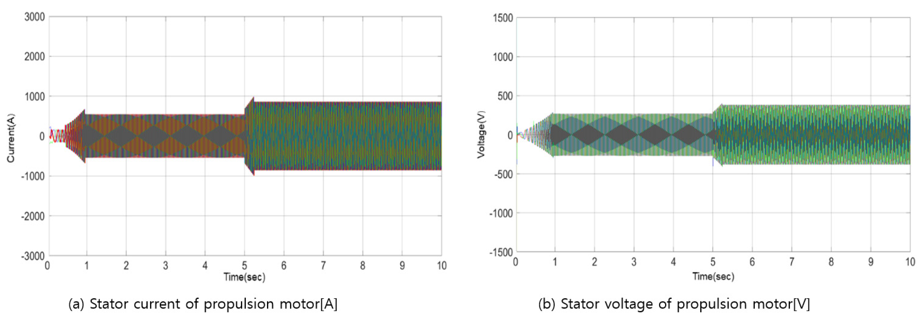
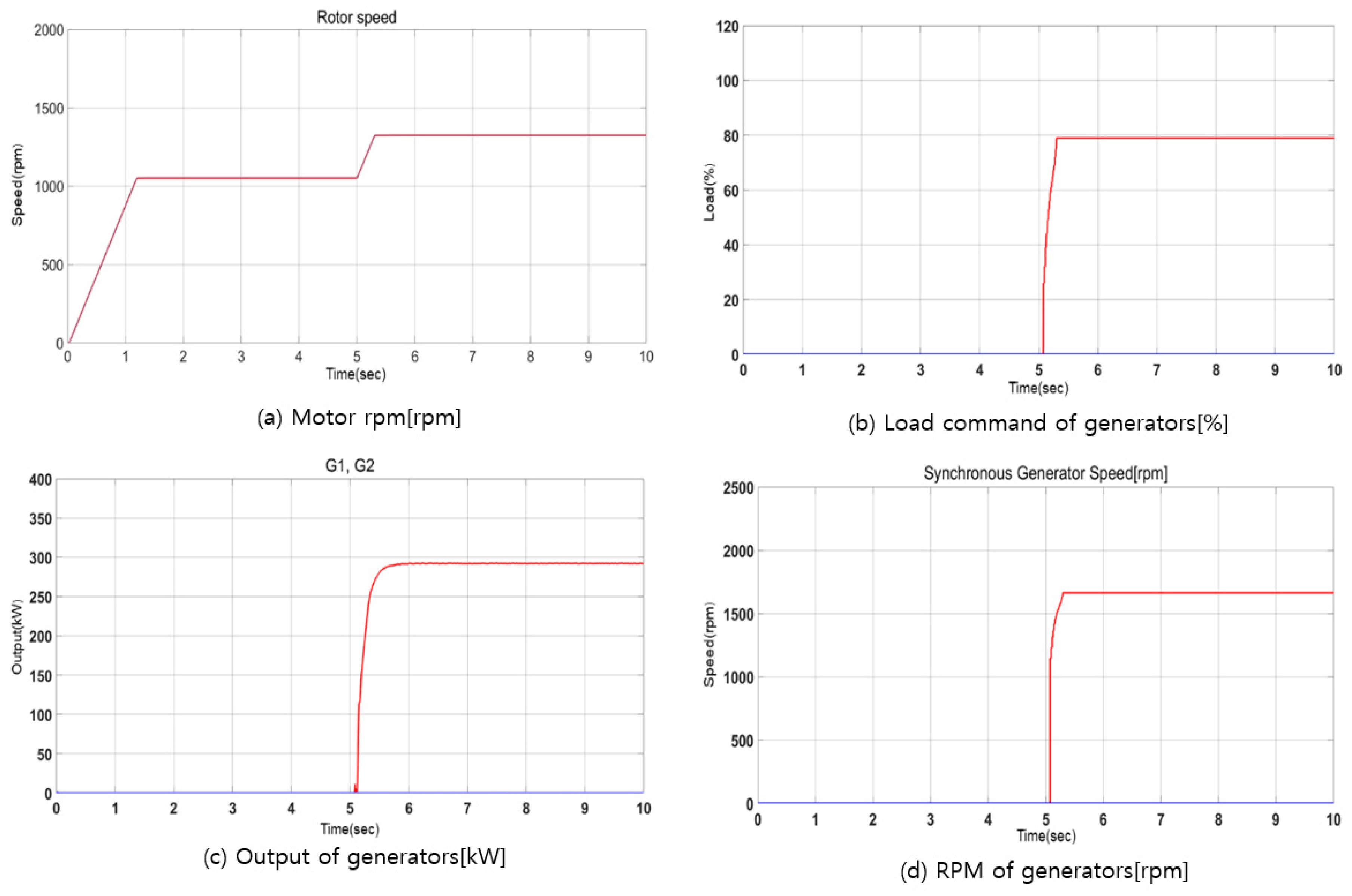
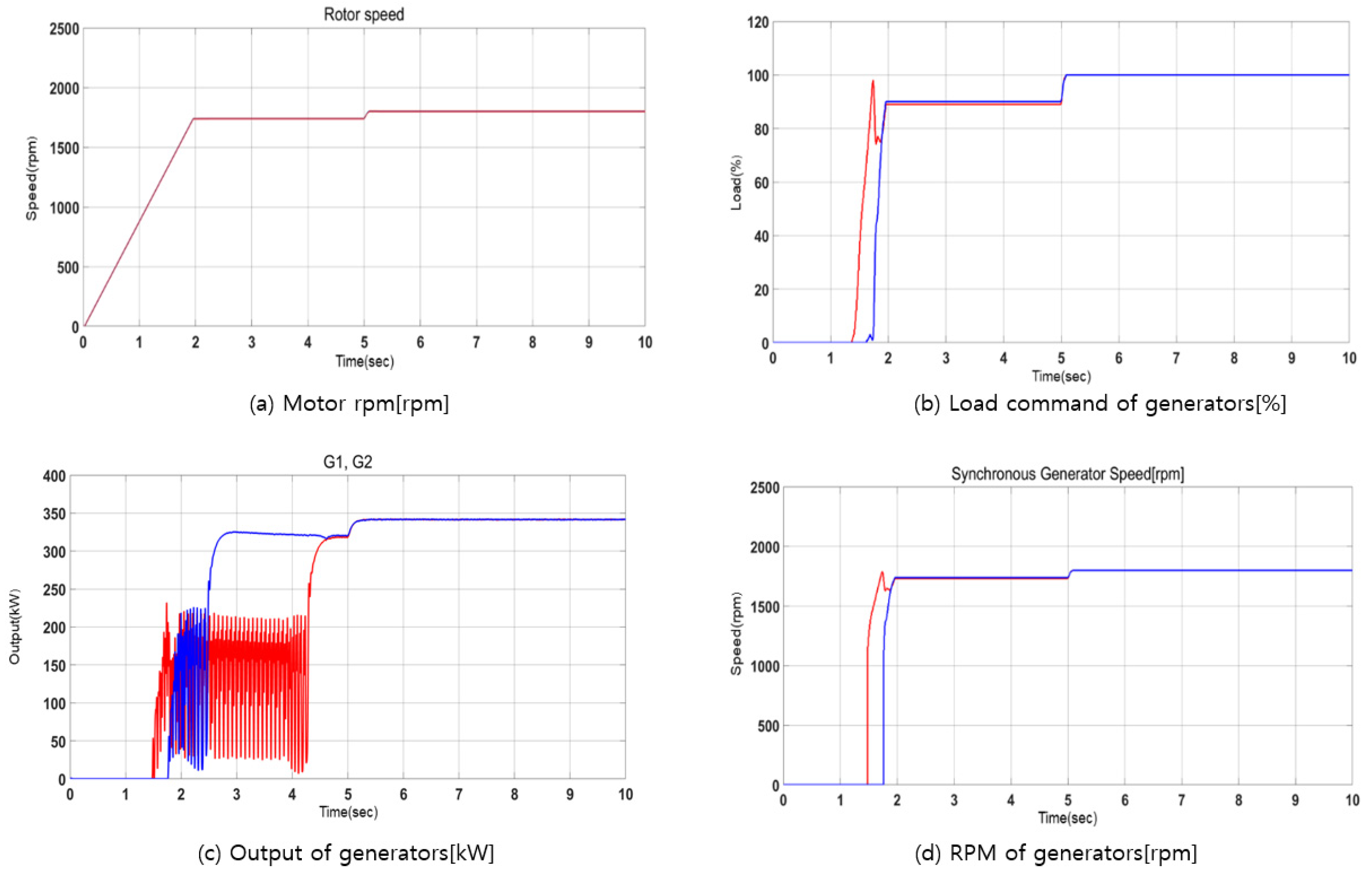
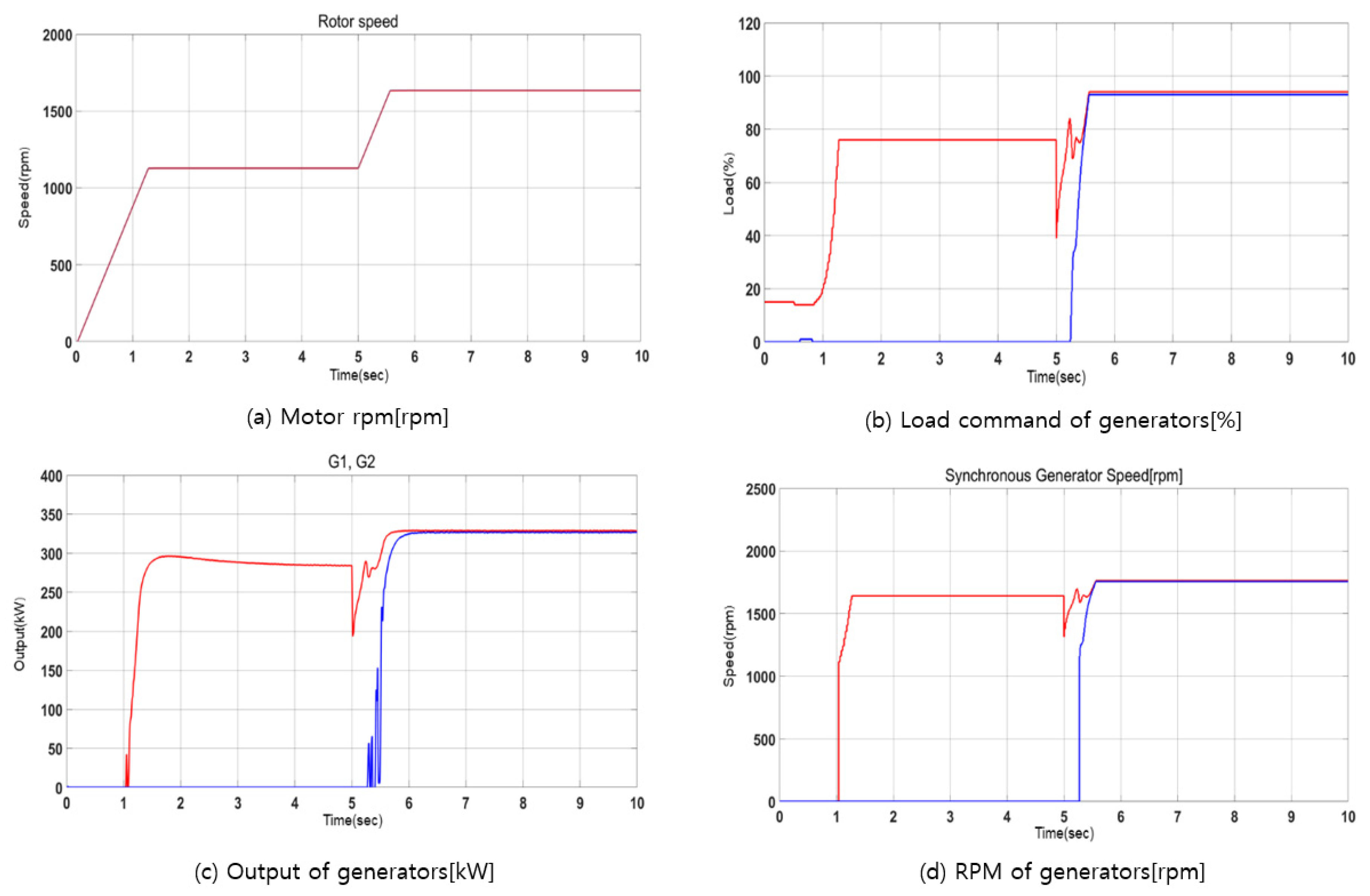
The stability of the propulsion system was verified in various load environments based on its speed, voltage, and current. Using the output of the neural network controller trained by the optimal energy control rules, simulations confirmed that the control was stably achieved based on the input load of the ship and battery SOC values. Even when these loads and SOCs were not among the input values used for the neural network training, the neural network output controlled the generator output, realizing stable operation of the propulsion motor.
(5)
If the control method developed in this study is used for other systems, optimal energy control will be possible. This is because the optimal connection weights could be obtained using the rule-based control logic provided by the designer as the input and output values for training the neural network.

Author Contributions

Conceptualization, S.K. and J.K.; methodology, S.K. and J.K.; software, S.K.; validation, J.K.; formal analysis, S.K.; investigation, S.K.; resources, S.K.; data curation, S.K.; writing—original draft preparation, S.K.; writing—review and editing, J.K.; visualization, S.K.; supervision, J.K.; project administration, J.K.; funding acquisition, J.K. All authors have read and agreed to the published version of the manuscript.

Funding

The Ministry of SMEs and Startups (MSS, Korea).

Institutional Review Board Statement

Not applicable.

Informed Consent Statement

Not applicable.

Acknowledgments

This work was supported by the Technology Development Program (P0016077) funded by the Ministry of SMEs and Startups (MSS, Korea).

Conflicts of Interest

The authors declare no conflict of interest.

References

  1. IMO. Initial IMO GHG Strategy. Available online: https://www.imo.org/en/MediaCentre/HotTopics/Pages/Reducing-greenhouse-gas-emissions-from-ships.aspx (accessed on 23 September 2021).
  2. European Commission. Reducing Emissions from the Shipping Sector. Available online: https://ec.europa.eu/clima/policies/transport/shipping_en (accessed on 23 September 2021).
  3. Wan, Z.; el Makhloufi, A.; Chen, Y.; Tang, J. Decarbonizing the international shipping industry: Solutions and policy recommendations. Mar. Pollut. Bull. 2018, 126, 428–435. [Google Scholar] [CrossRef] [PubMed] [Green Version]
  4. Al-Falahi, M.D.; Nimma, K.S.; Jayasinghe, S.D.; Enshaei, H.; Guerrero, J.M. Power management optimization of hybrid power systems in electric ferries. Energy Convers. Manag. 2018, 172, 50–66. [Google Scholar] [CrossRef] [Green Version]
  5. Stoumpos, S.; Theotokatos, G.; Boulougouris, E.; Vassalos, D.; Lazakis, I.; Livanos, G. Marine dual fuel engine modelling and parametric investigation of engine settings effect on performance-emissions trade-offs. Ocean Eng. 2018, 157, 376–386. [Google Scholar] [CrossRef] [Green Version]
  6. Lee, J.-H.; Lee, S.-H.; Sul, S.-K. Variable-Speed Engine Generator With Supercapacitor: Isolated Power Generation System and Fuel Efficiency. IEEE Trans. Ind. Appl. 2009, 45, 2130–2135. [Google Scholar] [CrossRef]
  7. Jeon, H.M.; Kim, S.; Kim, J. A Study on Application of Electric Propulsion System using AFE Rectifier for Small Coastal Vessels. J. Korean Soc. Mar. Environ. Saf. 2018, 24, 373–380. [Google Scholar] [CrossRef]
  8. Ghenai, C.; Al-Ani, I.; Khalifeh, F.; Alamaari, T.; Hamid, A.K. Design of Solar PV/Fuel Cell/Diesel Generator Energy System for Dubai Ferry. In Proceedings of the 2019 Advances in Science and Engineering Technology International Conferences (ASET), Dubai, United Arab Emirates, 26 March–10 April 2019; IEEE: Piscataway, NJ, USA, 2019; pp. 1–5. [Google Scholar]
  9. Son, Y.K. High-Efficiency Operation of Maritime DC Power System Consisting of Permanent Magnet Generator and Diode Rectifier; Seoul National University: Seoul, Korea, 2020. [Google Scholar]
  10. Yuan, L.C.; Tjahjowidodo, T.; Lee, G.S.; Chan, R.; Ådnanes, A.K. Equivalent consumption minimization strategy for hybrid all-electric tugboats to optimize fuel savings. In Proceedings of the 2016 American Control Conference (ACC), Boston, MA, USA, 6–8 July 2016; pp. 6803–6808. [Google Scholar]
  11. Chua, L.W.; Tjahjowidodo, T.; Seet, G.G.; Chan, R. Implementation of optimiza-tion-based power management for all-electric hybrid vessels. IEEE Access 2018, 6, 74339–74354. [Google Scholar] [CrossRef]
  12. Kanellos, F.D.; Anvari-Moghaddan, A.; Guerrero, J. A cost-effective and emission-aware power management system for ships with integrated full electric propulsion. Electr. Power Syst. Res. 2017, 150, 63–75. [Google Scholar] [CrossRef] [Green Version]
  13. Jaurola, M.; Hedin, A.; Tikkanen, S.; Huhtala, K. Optimising design and power management in energy-efficient marine vessel power systems: A literature review. J. Mar. Eng. Technol. 2019, 18, 92–101. [Google Scholar] [CrossRef] [Green Version]
  14. Kalikatzarakis, M.; Geertsma, R.; Boonen, E.; Visser, K.; Negenborn, R. Ship energy management for hybrid propulsion and power supply with shore charging. Control. Eng. Pract. 2018, 76, 133–154. [Google Scholar] [CrossRef]
  15. Syverud, T.H. Modeling and Control of a DC-Grid Hybrid Power System with Battery and Variable Speed Diesel Generators. Master’s Thesis, NTNU, Taipei, Taiwan, 2016. [Google Scholar]
  16. Motapon, S.N.; Dessaint, L.-A.; Al-Haddad, K. A Comparative Study of Energy Management Schemes for a Fuel-Cell Hybrid Emergency Power System of More-Electric Aircraft. IEEE Trans. Ind. Electron. 2014, 61, 1320–1334. [Google Scholar] [CrossRef]
  17. Dedes, E.K. Investigation of Hybrid Systems for Diesel Powered Ships; University of Southampton: Southampton, UK, 2013. [Google Scholar]
  18. Geertsma, R.; Negenborn, R.; Visser, K.; Hopman, J. Design and control of hybrid power and propulsion systems for smart ships: A review of developments. Appl. Energy 2017, 194, 30–54. [Google Scholar] [CrossRef]
  19. Lan, H.; Wen, S.; Hong, Y.-Y.; Yu, D.C.; Zhang, L. Optimal sizing of hybrid PV/diesel/battery in ship power system. Appl. Energy 2015, 158, 26–34. [Google Scholar] [CrossRef] [Green Version]
  20. Ghenai, C.; Bettayeb, M.; Brdjanin, B.; Hamid, A.K. Hybrid solar PV/PEM fuel Cell/Diesel Generator power system for cruise ship: A case study in Stockholm, Sweden. Case Stud. Therm. Eng. 2019, 14, 100497. [Google Scholar] [CrossRef]
  21. Yu, W.; Zhou, P.; Wang, H. Evaluation on the energy efficiency and emissions reduction of a short-route hybrid sightseeing ship. Ocean Eng. 2018, 162, 34–42. [Google Scholar] [CrossRef] [Green Version]
  22. Skjong, E.; Johansen, T.A.; Molinas, M.; Sorensen, A.J. Approaches to Economic Energy Management in Diesel–Electric Marine Vessels. IEEE Trans. Transp. Electrif. 2017, 3, 22–35. [Google Scholar] [CrossRef] [Green Version]
  23. La Tona, G.; Luna, M.; Di Piazza, M.C.; Pietra, A. Energy Management System for Efficiency Increase in Cruise Ship Microgrids. In Proceedings of the IECON 45th Annual Conference of the IEEE Industrial Electronics Society, Lisbon, Portugal, 14–17 October 2019; IEEE: Piscataway, NJ, USA, 2019; Volume 1, pp. 4056–4062. [Google Scholar]
  24. Rezk, H.; Nassef, A.M.; Abdelkareem, M.A.; Alami, A.H.; Fathy, A. Comparison among various energy management strategies for reducing hydrogen consumption in a hybrid fuel cell/supercapacitor/battery system. Int. J. Hydrogen Energy 2021, 46, 6110–6126. [Google Scholar] [CrossRef]
  25. Bassam, A.M.; Phillips, A.; Turnock, S.R.; Wilson, P. An improved energy management strategy for a hybrid fuel cell/battery passenger vessel. Int. J. Hydrogen Energy 2016, 41, 22453–22464. [Google Scholar] [CrossRef] [Green Version]
  26. Fallah, S.N.; Deo, R.C.; Shojafar, M.; Conti, M.; Shamshirband, S. Computational Intelligence Approaches for Energy Load Forecasting in Smart Energy Management Grids: State of the Art, Future Challenges, and Research Directions. Energies 2018, 11, 596. [Google Scholar] [CrossRef] [Green Version]
  27. Fitch, F.B.; McCulloch Warren, S.; Pitts, W. A logical calculus of the ideas immanent in nervous activity. J. Symb. Log. 1944, 9, 115–133. [Google Scholar]
  28. Hagan, M.T. Neural Network Design, 2nd ed.; PWS: Boston, MA, USA, 2014; p. 800. [Google Scholar]
  29. Hinton, G.E.; van Camp, D. Keeping the neural networks simple by minimizing the description length of the weights. In Proceedings of the Sixth Annual Conference on Computational Learning Theory-COLT ’93, Toronto, ON, Canada, 1 August 1993; ACM Press: New York, NY, USA, 1993; pp. 5–13. [Google Scholar]
  30. Barber, D.; Bishop, C.M. Ensemble learning in Bayesian neural networks. NATO ASI Ser. F Comput. Syst. Sci. 1998, 168, 215–238. [Google Scholar]
  31. Beşikçi, E.B.; Arslan, O.; Turan, O.; Ölçer, A. An artificial neural network based decision support system for energy efficient ship operations. Comput. Oper. Res. 2016, 66, 393–401. [Google Scholar] [CrossRef] [Green Version]
  32. Wen, S.; Zhao, T.; Tang, Y.; Xu, Y.; Zhu, M.; Fang, S.; Ding, Z. Coordinated Optimal Energy Management and Voyage Scheduling for All-Electric Ships Based on Predicted Shore-Side Electricity Price. IEEE Trans. Ind. Appl. 2021, 57, 139–148. [Google Scholar] [CrossRef]
  33. Yavasoglu, H.A.; Tetik, Y.E.; Ozcan, H.G. Neural network-based energy management of multi-source (battery/UC/FC) powered electric vehicle. Int. J. Energy Res. 2020, 44, 12416–12429. [Google Scholar] [CrossRef]
  34. Dinh, T.Q.; Bui, T.M.; Marco, J.; Watts, C.; Yoon, J.I. Optimal Energy Management for Hybrid Electric Dynamic Positioning Vessels. IFAC-PapersOnLine 2018, 51, 98–103. [Google Scholar] [CrossRef]
Figure 1. Generator–battery hybrid system using EMS.
Jmse 09 01228 g001
Figure 2. Specific fuel oil consumption and torque based on the speed and output of variable-speed generator.
Jmse 09 01228 g002
Figure 3. Generator–battery hybrid system with rule-based control employing ECMS.
Jmse 09 01228 g003
Figure 4. Design process of proposed generator–battery hybrid system with neural network.
Jmse 09 01228 g004
Figure 5. Voyage profile.
Jmse 09 01228 g005
Figure 6. Generator–battery hybrid system using neural network.
Jmse 09 01228 g006
Figure 7. Generator–battery hybrid system operation modes.
Jmse 09 01228 g007
Figure 8. Block diagram of operation sequence for proposed hybrid system.
Jmse 09 01228 g008
Figure 9. Block diagram of neural network estimator for determining optimal connection.
Jmse 09 01228 g009
Figure 10. Block diagram of proposed neural network controller.
Jmse 09 01228 g010
Figure 11. Error histograms of proposed hybrid system for neural network controller.
Jmse 09 01228 g011
Figure 12. Verification model for proposed neural network controller.
Jmse 09 01228 g012
Figure 13. Design values and verification results of proposed neural network controller.
Jmse 09 01228 g013
Figure 14. System configuration of generator–battery hybrid system using proposed neural network.
Jmse 09 01228 g014
Figure 15. Simulation model of generator–battery hybrid system architecture using neural network in vessel.
Jmse 09 01228 g015
Figure 16. Simulation model of converter and propulsion motor for generator–battery hybrid system architecture results.
Jmse 09 01228 g016
Figure 17. Simulation results of generators when load varies as 0 → 0%.
Jmse 09 01228 g017
Figure 18. Simulation results of system when load varies as 10 → 20%.
Jmse 09 01228 g018
Figure 19. Simulation results of propulsion motor when load varies as 10 → 20[%].
Jmse 09 01228 g019
Figure 20. Simulation results of propulsion motor and generators when load varies as 20 → 40%.
Jmse 09 01228 g020
Figure 21. Simulation results of propulsion motor when load varies as 20 → 40%.
Jmse 09 01228 g021
Figure 22. Simulation results of propulsion motor and generators when load varies as 40 → 40%.
Jmse 09 01228 g022
Figure 23. Simulation results of propulsion motor when load varies as 40 → 40%.
Jmse 09 01228 g023
Figure 24. Simulation results of propulsion motor and generators when load varies as 90 → 100%.
Jmse 09 01228 g024
Figure 25. Simulation results of propulsion motor when load varies as 90 → 100%.
Jmse 09 01228 g025
Figure 26. Simulation results of propulsion motor and generators when load varies as 25 → 75%.
Jmse 09 01228 g026
Figure 27. Simulation results of propulsion motor when load varies as 25 → 75%.
Jmse 09 01228 g027
Table 1. Proposed load-sharing rules.
PowerMode P G 1 P G 2 P b a t t
Load Condition
P b a t t   α < G m i n M1 G s t o p G s t o p P b a t t = P l o a d
G m i n   α < G m a x M2 G v a r = α G s t o p P b a t t = P l o a d   P G 1
G max   α < G 1 o p t + G 2 o p t M3-1Gopt   ( P l o a d P b a t t P G 1 o p t G m a x ) × 100 ( % ) = G v a r P b a t t = P l o a d P G 1 P G 2
G 1 o p t + G 2 o p t α   < G 1 m a x + G 2 m a x M3-2 G v a r = 1 2 ( P l o a d P b a t t G m a x ) × 100 ( % ) ,   P G 1 = P G 2 P b a t t = P l o a d P G 1 P G 2
G 1 m a x + G 2 m a x   α M 4 G m a x P G 1 = P G 2 P b a t t = P l o a d   P G 1 P G 2
Table 2. Results obtained by proposed rule-based strategy of generator–battery hybrid system for designing neural network controller (Mode 1: Green, Mode 2: Yellow, Mode 3: Pink, Mode 4: White).
Load [kW]1000900800700600500400300200100500
Load [%]10090807060504030201050
SOC
[kW]
310100[%]100, 10090, 9076, 7675, 4793, 064, 035, 00, 00, 00, 00, 00, 0
27990[%]100, 10090, 9076, 7675, 4793, 064, 035, 00, 00, 00, 00, 00, 0
24880[%]100, 10095, 9580, 8075, 5675, 2773, 044, 00, 00, 00, 00, 00, 0
21770[%]100, 10099, 9985, 8575, 6575, 3682, 053, 00, 00, 00, 00, 00, 0
18660[%]100, 100100, 10089, 8975, 7575, 4591, 062, 033, 00, 00, 00, 00, 0
15550[%]100, 100100, 10094, 9479, 7975, 54100, 071, 042, 00, 00, 00, 00, 0
12440[%]100, 100100, 10098, 9884, 8475, 6375, 3480, 051, 00, 00, 00, 00, 0
9330[%]100, 100100, 100100, 10088, 8875, 7275, 4389, 060, 031, 00, 00, 00, 0
6220[%]100, 100100, 100100, 100100, 10087, 8775, 7075, 4187, 058, 029, 029, 029, 0
3110[%]100, 100100, 100100, 100100, 10087, 8775, 7075, 4187, 058, 029, 029, 029, 0
00[%]100, 100100, 100100, 100100, 10087, 8775, 7075, 4187, 058, 029, 029, 029, 0
Table 3. Results of neural network outputs based on neural network inputs of proposed generator–battery hybrid system.
Neural Network InputRule-Based StrategyNeural Network Output
ItemLoadSOCG1G2G1G2
Unit[%][%][%][%][%][%]
100290301
20300010
310900000
420500001
54040800790
640075417541
79010090908990
8100100100100100100
92525N/AN/A730
107535N/AN/A9392
Table 4. Load environments for testing proposed generator–battery hybrid system.
StartAfter
ModeLoadSOCG1G2ModeLoadSOCG1G2
Initial start200290103000
Battery only11090001205000
Sole running120500024040800
Parallel running2404080034007541
Max. load39010090904100100100100
Random load22525730375359393
Publisher’s Note: MDPI stays neutral with regard to jurisdictional claims in published maps and institutional affiliations.

