1. Introduction
In order to limit the occurrence of fatalities, environmental damage and economic losses, marine structures are to be designed, built and operated in such manner that the probabilities of overall structural rigid body stability and failures are reduced to a minimum [
1]. During the design phase of a specific marine structure, a level of structural safety is chosen by defining individual structural elements, used materials and functional requirements. An important factor that has to be considered is the time dependency of the strength and loads. The strength of a structure decreases with time and true insight into the strength state strongly depends on inspection and maintenance procedures [
2]. As for the load, it is very variable through the lifetime of the marine structure.
Previous studies and analysis of marine structure failures had shown that a significant percentage of failures were a consequence of inadequate design due to a lack of operational considerations, incomplete structural element evaluations and incorrect use of calculation methods [
3]. Hence, in order to better understand the causes of failures, a failure analysis branch of engineering [
4] has developed over the years, serving as a help in the design optimization process. This discipline uses analytical, experimental and numerical tools in order to resolve failure causes. Particular effort has been invested in researching the causes of marine structural failures. Due to recent advances in failure analysis techniques and expected further improvement, it is essential to collect and review current state of the art research in the field and mark paths for future research.
A review of the present state of the scientific and practical development in this field, presented in this paper, should serve as an adequate starting point. The paper will present a brief review of indicative case studies dealing with marine structural failures. Marine structural failures can be divided into three main groups: failures of ships, offshore structures and marine equipment. Here, particular interest will be put on failures of ships, most specifically ship propulsion systems. One part of the paper will summarize experimental, analytical and numerical tools used for failure analysis. The result of this paper will define steps and possible analysis improvement recommendations that will be used as guidelines for future research in failure analysis of ship propulsion systems.
2. General Causes and Mechanisms of Failures
Structural failures occur when the loading exceeds the actual strength of the structure so they can be defined as a loss of the load-carrying capacity of the structure or some of its components [
5]. Failures can result in a global catastrophic damage that could easily lead to fatal casualties or partial damage that could lead to pollution or operational delay, but the structure can ultimately be repaired or recovered.
Structural failure is a result of fracture or damage that is initiated when the material is stressed above its strength limit. In particular, structural integrity of marine structures depends, along with the material strength and loading conditions, on material (usually steel) quality, proper manufacturing (usually welding), severity of service conditions (sea, salt, winds, etc.), design quality as well as various human elements that have effects during use of the structure [
6].
Causes of failures can be roughly divided in two distinctive groups. The first group is comprised of unforeseeable external or environmental effects which exert additional loading on the structure resulting in overload. Such effects are extreme weather (sea or wind overloads), accidental loads (collisions, explosions, fire, etc.), operational errors or environmental influence (corrosion). The second group comprises causes for failures that occur either during the design and construction phase (dimensioning errors, poor construction workmanship, material imperfections) or due to phenomena growing over time (fatigue, creep), both resulting in reduced actual strength in respect to the design value,
Figure 1.
Mechanisms of failures that occur in marine structures can have progressive or sudden natures. Structural designers tend, by all means, to avoid sudden failures like brittle fracture. Progressive failures, which depend on time and specific load conditions, can be monitored and adequate actions can be undertaken to avoid fatal scenarios.
One of such mechanisms, maybe the most important on ships and similar structures, is fatigue. Fatigue can be defined as a process of damage accumulated during each cycle of the dynamic load that the structure is subjected to with an important characteristic of load intensity lower than the values that would cause immediate failure [
7]. Fatigue cracks start and evolve in two phases—formation (usually starting on the material surface) of a shear crack on crystallographic slip planes in the first phase, and growth of the crack in a direction normal to the applied stress in the second phase [
8]. Cui proposed a division of the failure fatigue process in five stages, namely crack nucleation, microstructurally small crack propagation, physically small crack propagation, long crack propagation and final fracture [
9]. The process which occurs before long crack propagation is usually named “fatigue crack initiation”, while long crack propagation is called “fatigue crack propagation”.
The fatigue failure process is extremely complex in nature and dependent on a large number of parameters like distribution of mean stress, residual stresses, loading history, adequacy of design, environmental effects, manufacturing quality, etc.
Besides fatigue, corrosion effects on marine structures shouldn’t be neglected as another aging degradation effect on ship structural integrity [
10]. This gradual destruction of materials caused by chemical or electrochemical reaction with their environment weakens the material, opening discontinuities allowing for crack growth and final fracture. Coupled with fatigue, corrosion can indicate lowering of fatigue strength, accelerated initiation of failure at high stresses and elimination of the material’s fatigue limit [
11]. Furthermore, engineering designers strive to avoid stress corrosion cracking, the formation of microscopic cracks that can remain inconspicuous, but can cause crack formation in a mildly corrosive environment and lead to unexpected failures of ductile metallic materials. However, this paper is primarily concerned with mechanical causes of failure (overloading, fatigue, vibrations, etc.) that affect the structures with reduced strength, even if the reduction is a result of corrosion.
3. Tools Used for Failure Analysis
In order to fully understand the reviewed case studies of marine structural failures, an overview of tools used for failure analysis is desirable. Tools that researchers use are, in most cases, experimental and rely on some non-destructive testing (NDT) technique or microstructural analysis.
NDT plays significant role in failure analysis and control procedures [
12]. Classical (eddy-current, magnetic-particle, liquid penetrant, radiographic, ultrasonic and visual testing) or newly developed (e.g., acoustic emission) NDT techniques are used to gain insight into the actual state of the structure,
Figure 2. NDT methods must not alter, change or modify the actual condition of the structure, but must survey the failure so that they don’t impact, change or further degrade the failure zone. NDT is employed at the beginning of the service life in order to document initial flaws and monitor their progression. Based on these inputs, a structural health monitoring (SHM) strategy can be developed regarding damage detection and characterization [
13].
If necessary, destructive testing can also be employed, e.g., when the material mechanical parameters are not known and need to be determined. Here, researchers make use of tensile or impact tests performed on specimens extracted from failed structures. Hence, values of the material’s ultimate tensile strength, yield strength or Charpy V-notch impact energy,
Figure 3, can be determined and used for later numerical modelling [
14].
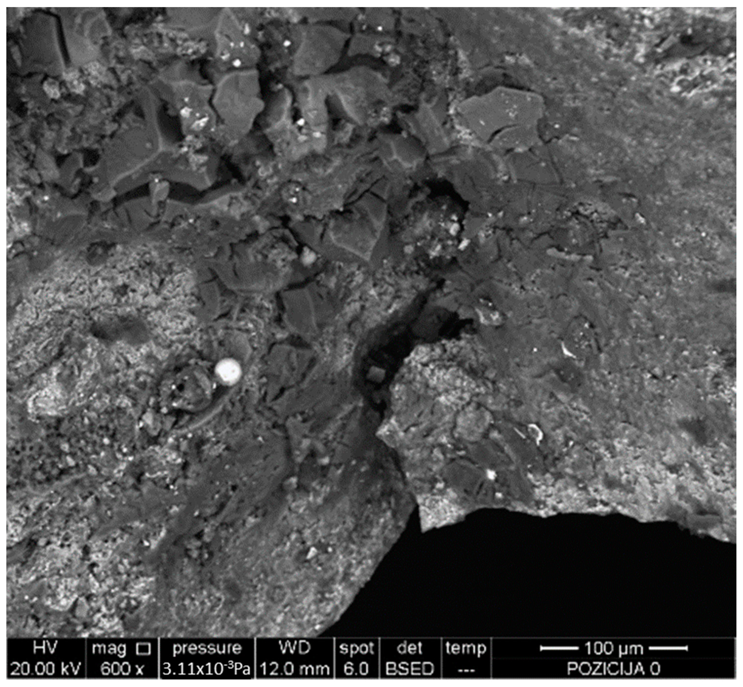
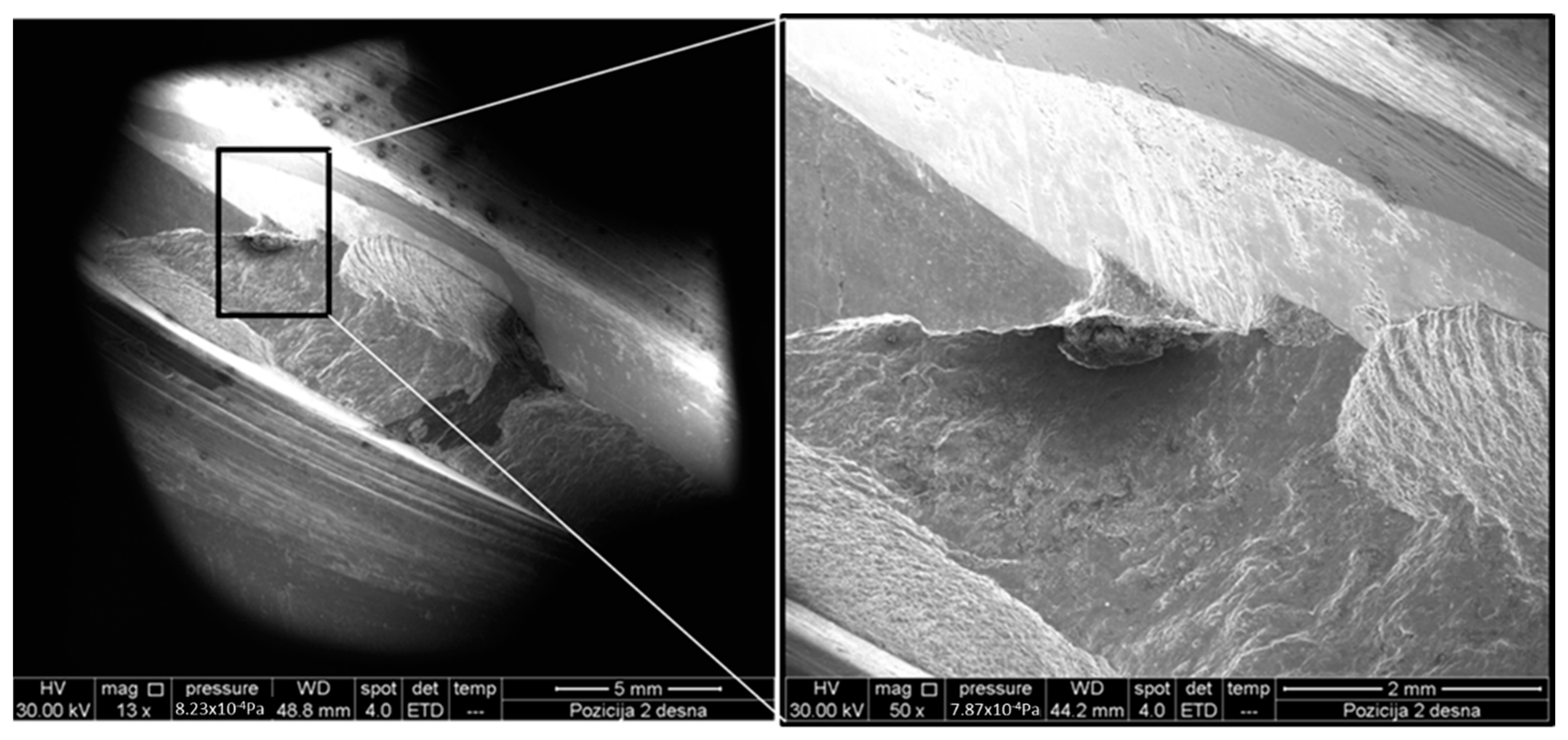
Microscopy, optical (OM) or scanning electron (SEM), is a widely used experimental failure analysis method providing insight into the metallurgical state of the fractured zone. This technique is often used in conjunction with micro-sectioning to broaden the application. One of the main disadvantages is the narrow field depth. SEM is an extension of OM and here the use of electrons instead of a light source provides higher magnification, better field depth and the opportunity to perform phase identification. SEM has been extensively used in the analysis of marine structures and equipment [
15,
16,
17,
18],
Figure 4.
Besides experimental, analytical solutions are also being used and further developed to allow fast and reasonably accurate prediction of damage. Analytical procedures are usually based on spectral fatigue analysis, beam theory, fracture mechanics and structural factors. One of the concepts that can be applied is the failure assessment diagram (FAD) approach that spans the entire range from linear elastic to fully plastic behavior of the material preceding the fracture.
The FAD is basically an alternative method for graphically representing the fracture driving force. Depending on the type of the equation used to model the effective stress intensity factors the FAD approach can be sub-divided into the strip-yield based FAD [
19],
J-based FAD [
20,
21,
22] and approximated FAD. It uses two parameters which are linearly dependent on the applied load. The result is a curve that represents a set of points of predicted failure points and the results fall in acceptable or nonacceptable areas marked by that curve. This method can be applied to analyze and model brittle fracture (from linear elastic to ductile overload), welded component fatigue behavior or ductile tearing.
Another factor that has to be considered are dynamic loads imposed onto the marine structures and their unpredictable, stochastic changes. Probabilistic failure analysis can account for time-dependent crack growth by applying appropriate distribution laws. Most practical situations exhibit randomness and uncertainty of the analysis variables so numerical algorithms for probabilistic analysis may need to be applied. The well-known Monte Carlo method can suit FAD models in most cases of uncertainties [
23].
The marine industry relies heavily on standards and regulations set by classification societies that have recently been involved in research and development in order to establish probabilistic methods that are to be used for planning in-service inspection. Det Norske Veritas issued recommendations on how to use probabilistic methods for floating production ships, among others [
24,
25]. The goal of proposed probabilistic method is to replace conservative inspection planning with mathematical models that consider the influence of exploitation, fatigue causes and crack propagation characteristics on structure lifetime.
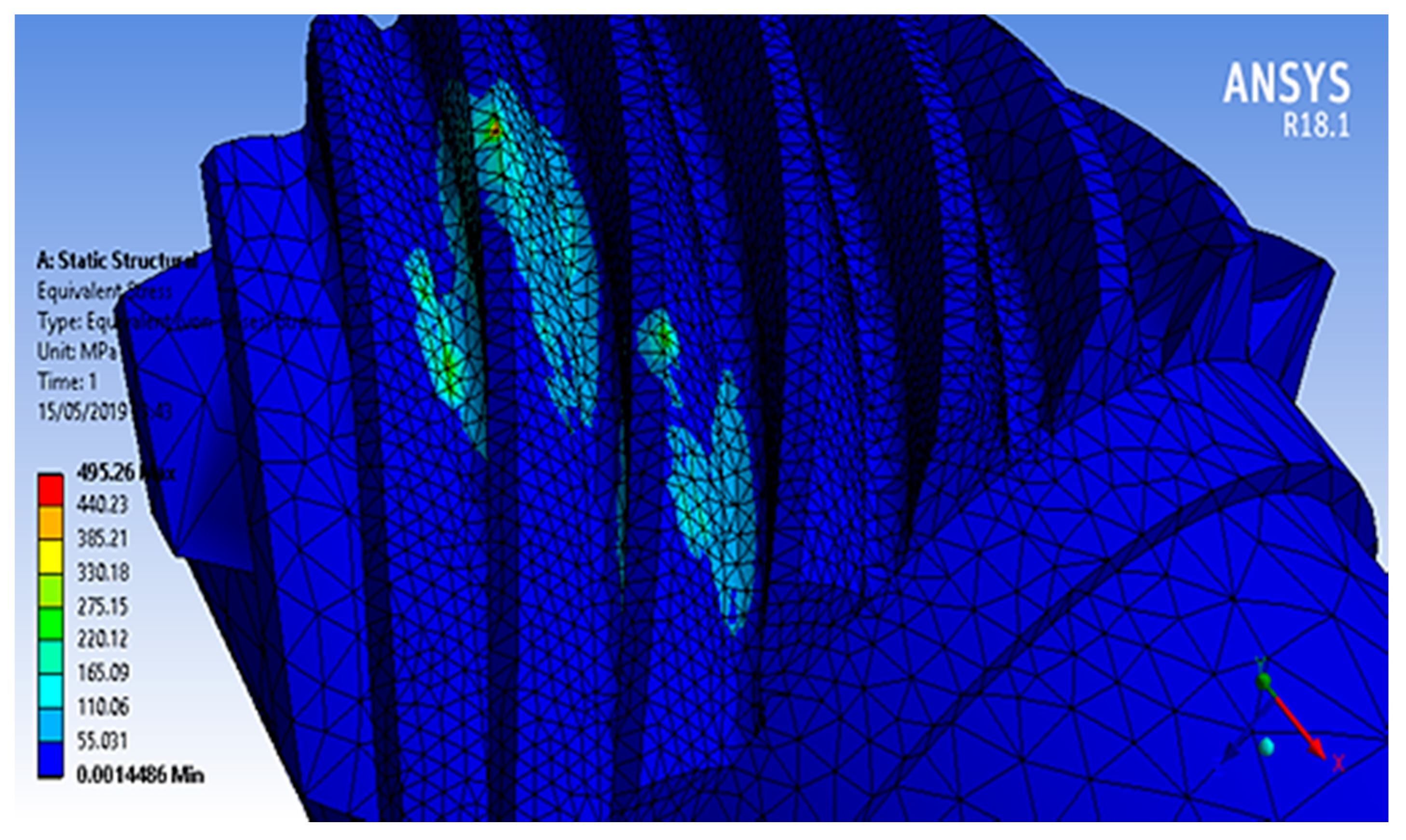
Furthermore, with the development of advanced numerical routines and powerful computers, more and more research is done using some kind of numerical analysis. The latest trend in failure analysis development is the unification of analysis methods and procedures [
26,
27,
28] in order to obtain a comprehensive procedure of structural failure analysis that would cover the main failure modes and enable a safer and more efficient design, manufacturing and maintenance processes. Out of the numerous various methods used, the finite elements (FE) method has been recognized for its universality and efficiency,
Figure 5.
The extended FE method (X-FEM) is the most recent development used mostly for fracture mechanics. It can be applied to solve complex discontinuity issues including fracture, interface and damage problems while proving useful in multi-scale and multi-phase computation [
29]. The basic idea is to reduce the re-meshing around the crack so as to enable the crack to be represented independently of the mesh [
30], even in 3D applications [
31,
32,
33].
Various adaptive re-meshing techniques for crack growth modelling have been developed in order to better account for discontinuities and allow time-saving calculations. One of them is the automatic crack box technique (CBT), developed to perform fine fracture mechanics calculations in various structures without global re-meshing [
34]. Only the specific crack tip zone has to be re-meshed resulting in quick calculations.
4. Ship Propulsion System Failures
Ship propulsion system failures include failures of shaft lines, crankshafts, bearings, foundations, etc. The causes of ship structure failure can be external (impact, bad weather) or internal (inadequate dimensioning, material grade, fatigue, etc.).
Ship propulsion systems are subjected to vibrational [
35], torsional [
36], coupled longitudinal (axial) [
37] (
Figure 6), and lateral [
38] loads. Vibrations can cause fracture and failure in system components or on the ship’s structure, resulting in complete destruction of the propulsion system, reduction of the service life of shafts and/or their components and fatigue fracture on support brackets and/or engine mountings. The shafts line’s misalignment [
39] or bend represent one of the most frequent reasons of this kind damages.
Moreover, it has been experimentally proved that frictional losses during power transmission through the universal joints could act as an excitation force for self-excited vibrations [
40] of shafting in the propulsion systems of an ocean-going vessel. Research revealed that undamped vibrations will cause failure if coupling connected to the intermediate shaft doesn’t have sufficient radial flexibility. Coupling should be designed so that is capable of absorbing the radial shaft displacement, therefore avoiding the effects of the self-excited torsional vibration.
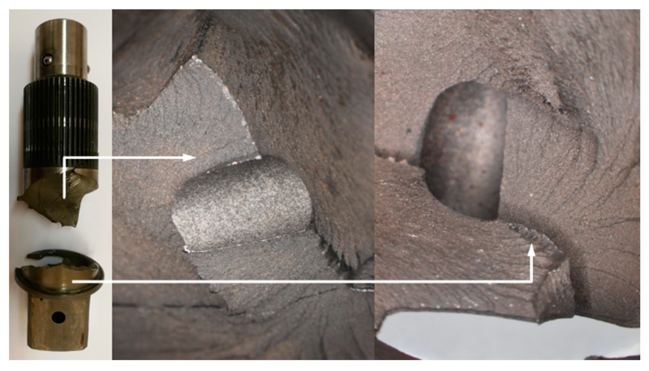
Cracks usually occur in flanges, shaft liners, shaft end and keyways. The causing factors can be grouped in design, workmanship and operation cause groups. A keyway’s end design represents a stress concentration point during torque transmission through shaft keys. Poor final processing of key grooves, keyways and keys, inadequate run out radius or material impurities can act as root causes of torsional fatigue failure in shaft keys. This characteristic failure can be recognized as a crack pattern initiating at the keyway end and propagating in a 45° rotational direction marking a helical path,
Figure 7. Solved case studies [
41,
42] have revealed that deficient design against torsional vibrations (i.e., calculations of shaft elements stiffness and damping, natural frequencies, safety factors) causes failures of the shaft’s keyway. In the referenced researches root-cause analysis has been performed combining analytical processes set by MIL G 17859D and VDI 3822 standards with FE analysis.
Propulsion shaft elements can fail while running at low speed due to fatigue caused by torsional stress [
43]. The cause of the failure in this particular case was exposure to corrosive environments without any protective coating which resulted in pitting corrosion. The crack grew with multiple starting points due to torsion force (moment) with high stress concentrations, i.e., the failure cause was fatigue and corrosion.
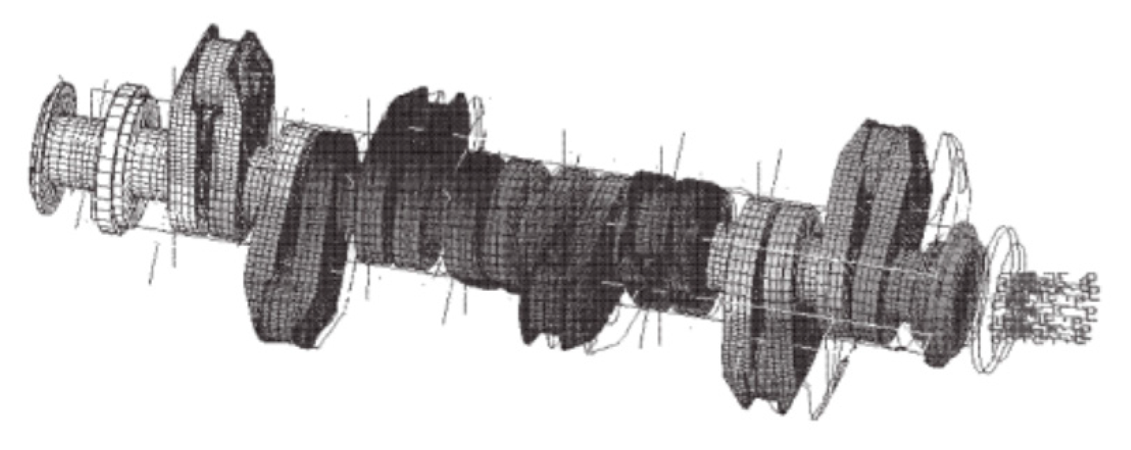
Engine crankshafts are subjected to bending, stretch–compression, and torsional dynamic loads. Thermal displacement (caused by normal engine working conditions) of the crankshaft [
44] and thermal interaction between main engine body and ship hull [
45] are other sources of variable loads acting on power transmission system. Therefore, the crankshafts are prone to fatigue failures under multiaxial loading. A fatigue analysis for a typical marine crankshaft has shown that a combination of rotating bending with steady torsion stress caused formation of a crack initiated by rotating bending, whilst the effect of the steady torsion became itself significant in the later phases of crack growth. The fact that the propagation was fast in comparison with the total number of the engine work hours indicates that the failure was caused by fatigue [
46].
One first indication of failure in a crankshaft is given by the low-pressure value of the lubrication circuit. This is mainly due to the accumulation of debris in the lubrication channels, which causes the oil filters to be clogged. As such, this will cause poor lubrication of the crankshaft, which can consequently cause its catastrophic failure, and frequently originates damage propagation to other components of the engine, namely the crankcase, bearing shells, connecting rods, pistons and other mechanical parts [
47].
Gomes at al. [
48] performed failure analysis of a maritime V12 diesel engine crankshaft. A series of failures of the crankshafts were reported over a quarter of a century. The authors discussed the influence of material imperfections and applied load to the crankshaft failure but also performed dimensioning assessment using the Soderberg criterion FE crankshaft model. A stress-life equation was used to estimate the fatigue lifetime of the crankshaft so, finally, a modification to the crankshaft’s design is suggested to reduce induced stresses. This case study can serve as a showcase for a comprehensive failure analysis that will be discussed in later sections of this paper.
As seen in a previous case study, fillets, tapers and chamfers also represent stress concentration points in shafts and their improper design can lead to fatigue failure. An additional case study of fracture initiated at a fillet [
49] shows fatigue failure due to a cyclic torsional-bending load acting on a crack emanating from the fillet shoulders on the shaft. Gradual shaft load bearing reduction led to consequential overloading and final sudden failure. Chemical composition analysis, microstructural characterization, fractography, hardness measurements and FE analysis were incorporated in this research to determine the failure causes.
Spline joints are adequate alternatives to shaft key joints but previous research has shown that the press fitting of the joining elements can cause strains leading to surface crack formation [
50]. Spline teeth at the shaft junction zone is the usual crack origin, alternating stress causes crack growth and propagation. Imperfections of the material can further ease crack propagation. This particular case study comprised of a visual and macroscopic inspection, material analysis, hardness measurement, OM and SEM.
Changes of the shaft rotation direction can result in torque moment overloading acting on bolted connections that are used in collar coupling of shaft elements and in propeller blade connections. This can result in fatigue failure of coupling bolts [
51]. Fretting creates micro notches that develop into fatigue cracks with a direction of the crack path growing in planes angled from 35° to 60°. As this is not a characteristic of pure torsion fatigue, failure analysis has been performed to shown that the bolts are subjected to an increasing bending moment. Here, experimental findings served as an input for numerical verification of the hypothesis that variable bending stress in the coupling served as the cause of failure.
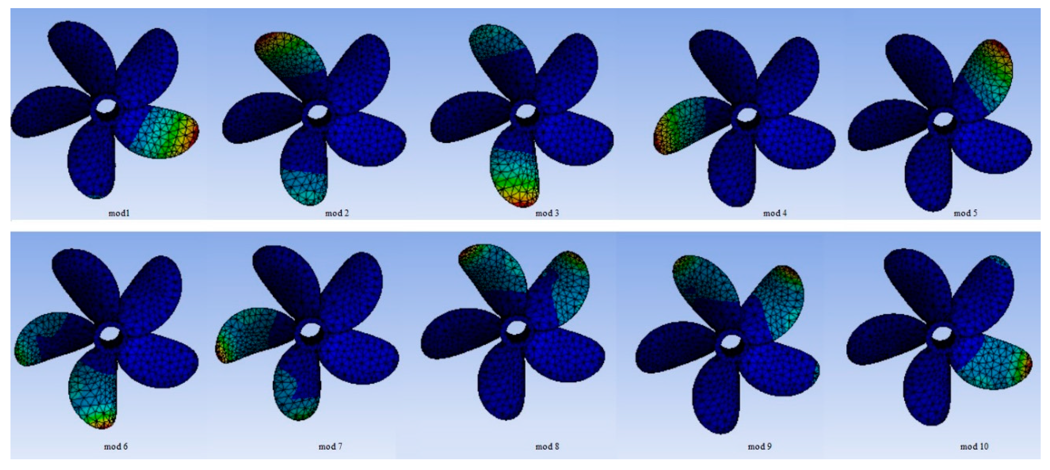
Damage of one or several blades can cause abnormal performance of the ship’s propeller. This can generate uniaxial force which fluctuates once per rotation in a consistent transverse direction across the shaft. This fluctuating force generates a couple which can cause fatigue failure of the propeller hub [
52]. A uniaxial type of failure is characterized by a fatigue fracture with a single origination point that progresses across the shaft from the side where the force is being applied and results in the final overload failure occurring on the opposite side from the fluctuating force. Visual inspection, detail axis alignment measurements, microscopic metallurgical examination, hardness measurements and ultrasonic scanning were used in this case study. Numerical modal analysis could prove useful here to determine natural mode shapes and frequencies of a propeller in order to avoid them during operation,
Figure 8.
AHTS (Anchor Handling/Tug/Supply) ships use ducted azimuth thrusters for propulsion. The integral part of such propulsion system is the gears used for power transmission. Gear failures can occur due to localized stress increase on the teeth surface which is caused by inadequate lubricating and constructional misalignments, i.e., poor maintenance and design [
53]. Additionally, gear failures can be initiated at locations with material inclusions, serving as stress raisers,
Figure 9.
The exhaust systems of marine engines and gas turbines are subjected to high service temperatures which can contribute to the reduction of the service life of the system. These structures are usually constructed as welded steel plate structures, with cracks occurring in the welded joints [
54]. In conditions of thermal shock and temperature variations, the lifetime of the structure can be influenced significantly as the critical crack size is reduced.
5. Discussion
Two main types of ship structure can be distinguished: ship hull (with superstructure and main engine body) and power transmission system (i.e., crankshaft, shaft line and propeller). Ships operate in aggressive workload and environmental conditions so proper assessment of the technical condition is crucial from the perspective of safety of maritime navigation. Limitation of maritime disasters is of great economic importance and, more importantly, will reduce the negative environmental impact along with human injuries and life losses. Especially the propulsion system of the ship should be subject to thorough assessment, because inoperative propulsion results in a very high probability of disaster in extreme weather conditions.
In order to cope with such requirements, engineering designers rely heavily on the regulations prescribed by the classification societies. Classification societies’ rules are based on a wide knowledge collected over hundreds of years and are mostly based on simplified, empirical equations. However, not all the problems occurring on modern ships can be successfully solved using this approach. To properly address issues of marine structural failures, engineers need to turn to failure analysis databases and, learning from the findings, improve procedures for ship designing.
Reviewing case studies in a former section, one can notice that most of them use solely experimental approaches in finding the causes of failures. Techniques like NDT inspection, microscopy or crystallography are used in order to determine the origins of failures. Only a few use numerical analysis as a supplement to traditional experimental techniques used in the field of failure analysis. However, those who do combine experimental and numerical approaches tend to present more reliable results and go a bit further than usual failure analysis does—they suggest modifications to engineering design. So, a combination of failure analysis and design optimization is arising here.
If one goes a step further and tries to identify case studies of failures where experimental and numerical approaches are complemented with analytical analysis, one can find that they are very rare. Only a few case studies (dealing with marine structural failures) can be found that, based on experimental and numerical results, propose an improvement of analytical procedures used in calculations of structures against failures.
So, it is obvious that these separate science disciplines and branches need to bring themselves closer in order to mutually improve. The first step is performing thorough failure analysis—analysis that would incorporate inevitable experimental, numerical and analytical procedures. Experimental, to determine material characteristics and origins of failure. Numerical, to model the structure, analyze its real performance and optimize the design. Analytical, to model complex natural and technical phenomena and then convert them into simple mathematical models. A mathematical model may help to explain a system and to study the effects of different components and to make predictions about behavior. At this stage, failure analysis (or forensic) engineers must work closely with metallurgists, NDT engineers, engineering designers, FEM experts, mechanical engineers, mathematicians, etc. [
55,
56].
These failure analysis findings should prove valuable in improving analytical procedures defined by rules and regulations that are set by classification societies. The shipping industry is conservative in nature, but all classification societies admit alternatives to their calculation methods, especially FEM. These, more detailed, analyses are usually more expensive but optimization is possible.
Another important aspect, especially in the stage of numerical research, is proper modelling of loads imposed on marine structures. Numerical algorithms used for, e.g., FE analysis of ship mechanical behavior, must account for the randomness and uncertainty of loads coming from sea, wind, operating machinery and moving cargo loads. Using the principles of probabilistic mechanics these problems can be solved successfully and greater safety of navigation can be granted for ships.
Learning from the cases shown in the previous section, several possible research directions can be suggested. These are:
improved design methodologies,
condition based monitoring techniques,
a coupled failure analysis approach.
Improved design methodologies need to take into the account previously acquired practical knowledge about the operation of marine structures and machinery [
57], but also need to rely on modern computer-based design and findings from the operational monitoring data and eventual failure analysis. That way, costly and time-consuming experiments can be successfully substituted, the design process can be shortened and safety factors, often too conservative, can be reduced.
Condition based monitoring techniques [
58], if introduced for rotating machinery, are most commonly based on vibration and lubrication monitoring [
59]. These two techniques prove themselves valuable as they fall into the category of preventive prediction tools, where the monitored machinery can still be satisfactory repaired if unusual values of vibrations or dispensed particles are detected. In addition, ultrasonic detection of failures can also be introduced to ships to detect failures in the early stages, but this technique requires highly skilled operators. Research in this field should find a way to introduce practical and reliable solutions for these techniques to be introduced to ships in order to detect potential failures in the early stages.
The coupled failure analysis approach assumes that adequate failure analysis can no longer be based solely on the techniques such as metallography, microscopy and other experimental methods. Today, experimental methods coupled with big-data acquisition and FE methods provide adequate means of achieving higher degrees of marine machinery safety, suitable operational life prediction and analysis of mechanical failures. Further research in this field should concentrate on blending these two approaches and developing new solutions in FE analysis. These new solutions should seek to close the existing gaps in multi-scale fracture mechanics, transition from damage to fracture, interaction of fracture with heat and moisture transport, dynamic fracture and fatigue prediction [
60].
Successfully addressing these research issues could help to reduce the possibility of future failures of marine propulsion systems.
6. Conclusions
In this paper, recent work on the topic of ship failures has been outlined. The list is not exhaustive as literally every day new reports and papers are being published. However, the case studies mentioned here were selected to benchmark the common causes of failures on ships. Further cases can be found, of course, but with the same or similar causes of failures and that is why they were omitted.
Particularly, the failures of ship structures and propulsion systems have been summarized and described. As for the former, it can be noted that failures can be caused either by unfavourable environmental conditions (low temperatures, corrosive surroundings), poor design or workmanship (particularly concerning welds) or fatigue loading that is very often stochastic in nature. As for the latter, causes include inadequate design or assembly (of shaft line) or fatigue very often coupled with fluctuating torsional vibrations.
Some light is shed on the general causes and mechanisms of failures and an overview of the tools used in failure analysis is given. Points for further development of failure analysis are given in the Discussion section mentioning the unification of analysis methods and procedures in order to obtain a comprehensive procedure of structural failure analysis that would cover the main failure modes and enable safer and more efficient design, manufacture and maintenance processes and usage of maritime structures.
This review paper can serve as an introduction to the area of ship failure analysis for new coming engineers, practitioners and researchers or as an initial step in studying structural integrity of rotating machinery [
61].


