Article

Accuracy Assessment of Satellite-Based Correction Service and Virtual GNSS Reference Station for Hydrographic Surveying

by
Mohamed Elsayed Elsobeiey
Department of Hydrographic Surveying, Faculty of Maritime Studies, King Abdulaziz University, Jeddah 21589, Saudi Arabia
J. Mar. Sci. Eng. 2020, 8(7), 542; https://doi.org/10.3390/jmse8070542
Submission received: 15 June 2020 / Revised: 9 July 2020 / Accepted: 16 July 2020 / Published: 20 July 2020
(This article belongs to the Special Issue Advances in Navigability and Mooring)

Abstract

:
The aim of this paper is to assess the performance of satellite-based correction service, Trimble PP-RTX, and Virtual Reference Stations (VRS) for bathymetry determination, and check how far these techniques meet the minimum standards of the International Hydrography Organization (IHO) for hydrographic surveys. To this end, a three-hour duration session was conducted at Sharm Obhur using KAU-Hydrography 1 vessel. This session includes Global Navigation Satellite System (GNSS) data at the base station using Trimble SPS855 GNSS receiver, multibeam records using Kongsberg EM 712 multibeam echo sounder, sound velocity profile using Valeport’s sound velocity profiler, Applanix POS MV measurements, and real-time PP-RTX corrections. Moreover, the VRS GNSS data was generated using Kingdom of Saudi Arabia Continuous Operation Reference Station network (KSA-CORS). It is shown that the Total Horizontal Uncertainty (THU) and Total Vertical Uncertainty (TVU) of the PP-RTX technique are 5.50 cm and 5.90 cm, respectively, which meets the IHO minimum standards for all survey orders at 95% confidence level. The THU and TVU of the VRS technique, on the other hand, are 5.75 cm and 7.05 cm at 95% confidence level, respectively. These values meet the IHO standards for all survey orders as well. Statistical analysis of the seabed surface differences showed a −0.07 cm average difference between the PP-RTX seabed surface and the reference seabed surface with a standard deviation of 3.60 cm. However, the average difference between the VRS-based seabed surface and the reference seabed surface is −0.03 cm and a standard deviation of 3.61 cm.

1. Introduction

Safe marine navigation requires an accurate bathymetry determination. Typically, differential carrier-phased-based Global Navigation Satellite System (GNSS) techniques are used in high-accuracy surveying applications. These techniques inherit their high accuracy from the fact that both the GNSS base and rover receivers are close and share the same errors and biases [1]. The shorter the baseline is, the more there is similarity of errors and biases at both stations. As such, the effects of orbital errors, ionospheric, and tropospheric errors are significantly reduced by forming differenced observables [2]. However, as the baseline length increases, the errors at the reference and the rover receivers become less correlated and they would not cancel out sufficiently through differencing [3]. This leads to unsuccessful fixing for the ambiguity parameters, which in turn deteriorates the positioning accuracy [4]. Therefore, it is very important to have short baselines, by using reference base station close to the rover. To overcome the baseline length limitation, both global commercial satellite correction services, e.g., Trimble CenterPoint RTX (Real Time eXtended) and Virtual reference station (VRS) represent good alternatives.

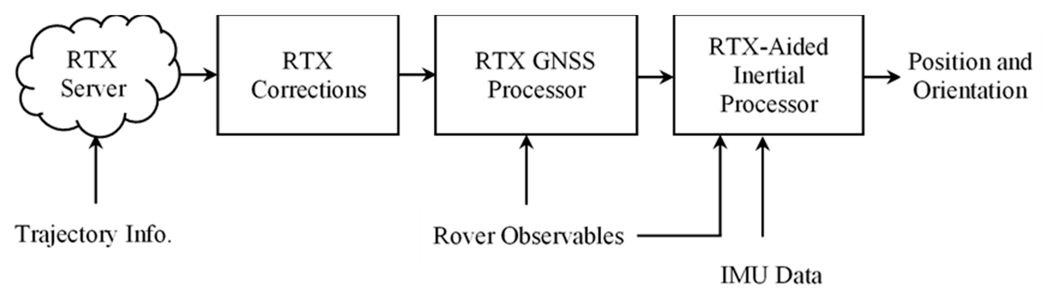
1.1. Trimble PP-RTX Technique
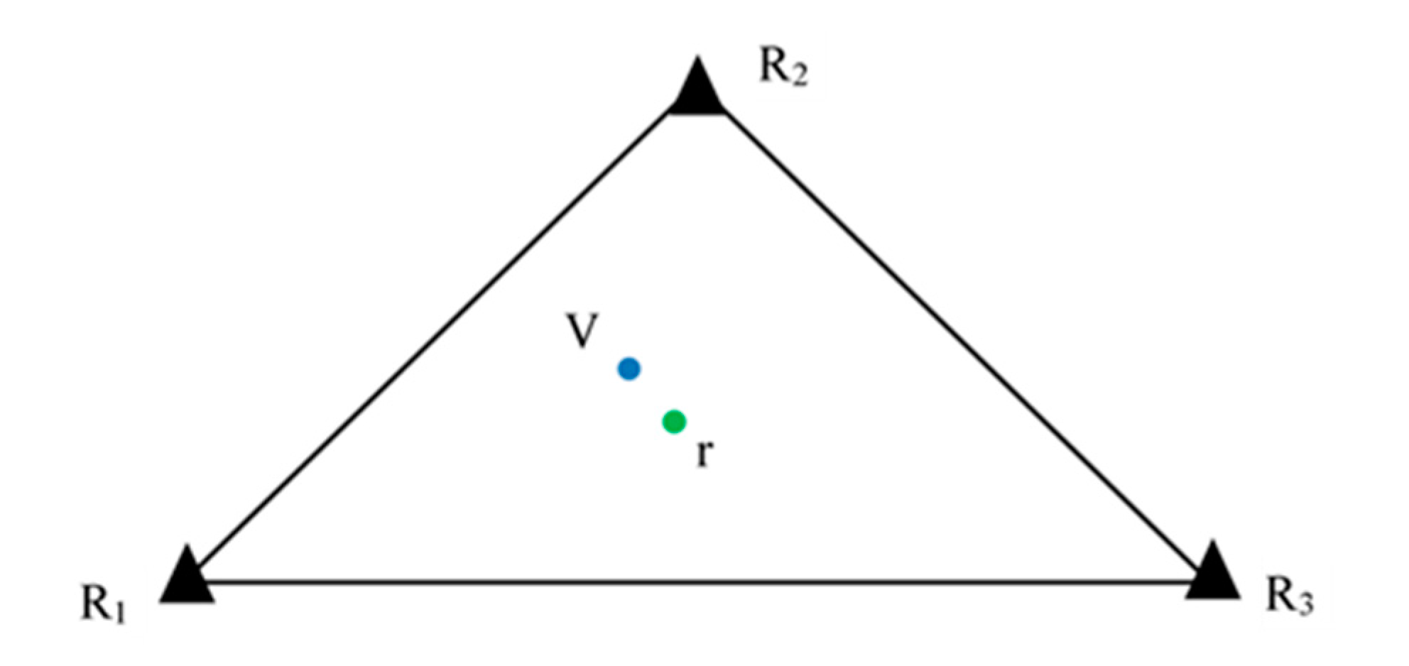
Trimble CenterPoint RTX technology utilizes real time GNSS data from globally distributed network of tracking stations to generate Trimble RTX corrections. Such corrections include precise satellite orbits, satellite clock corrections, and observation biases for any location on the earth at a rate of 1 Hz [5]. The corrections are then delivered to subscribers via a set of geostationary satellites or by the internet [6,7]. The mathematical models for corrections generation are out of the scope of this paper and may be found in detailed elsewhere [8]. According to a previous study [9], the horizontal accuracy of Trimble RTX service ranges from 2.00–50.00 cm root mean square (RMS), depending on the subscription level, and the vertical accuracy is 5.00 cm. However, an initialization time of 1–20 min is required depending on the subscription level.
PP-RTX is a high accuracy post processed RTX-aided inertial processing method that utilizes the precise corrections derived from Trimble RTX. This technique has been developed and implemented in Position and Orientation System Post-Processing Package Mobile Mapping Suite (POSPac MMS) to enable cm level positioning for mobile mapping without the need for a reference station. Figure 1 shows the PP-RTX implementation in POSPac MMS [10].
The PP-RTX is available 1 h after data collection and horizontal and vertical accuracies are less than 3.00 cm and 6.00 cm, respectively. To reach full accuracy, mission duration of about 30 min is required for standard PP-RTX [10].

1.2. VRS Principles

Virtual reference station (VRS) is one of main important solutions for high precision real-time kinematic (RTK) applications [11]. The idea is to utilize real observations from an existing network of multiple reference stations to generate observations at a specific location of a nonexisting station, i.e., a virtual station [2]. In this case, VRS data will be used as if they were collected from a normal local reference station [12]. Hence, neither special data format nor software changes in the rover receiver are required to use the VRS approach [13].
In general, the data from at least three reference stations surrounding the VRS is used to calculate the measurements at the VRS. Figure 2 shows an example of three reference stations (R1, R2, and R3) with VRS denoted as V and rover receiver indicated as r. Coordinates of the reference stations are known and fixed. However, the position of the VRS is assumed as the approximate position of the rover receiver to assure that short baselines are formed.
The general form of the mathematical models of the carrier-phase observables can be written as follows [14]:
Φ ( t ) = ρ ( t ) + c d t r s ( t ) + λ N r s + Δ r s ( t )
where, Φ ( t ) is the carrier-phase measurements at specific time t, scaled to distance (m); d t r s = [ d t r d t s ] represents the difference between receiver clock error d t r and satellite clock error d t s ; λ is the carrier-phase wavelength; N r s is the carrier-phase ambiguity integer number; c is the speed of light in vacuum (m/sec); ρ is the true geometric distance between satellite antenna phase center and receiver antenna phase center at reception time (m); Δ r s = Δ T r o p + Δ I o n o + Δ O r b i t is the summation of the slant tropospheric delay Δ T r o p , ionospheric delay Δ I o n o and orbital error Δ O r b i t .
Since the reference stations coordinates are known, baselines of the reference network can be solved and the carrier-phase ambiguities can be determined. The results of reference network processing include the residual error for all reference stations and at each processed epoch Δ r s ( R 1 , t ) , Δ r s ( R 2 , t )   and   Δ r s ( R 3 , t ) . Denoting R for reference station and V for virtual reference station, Equation (1) can be written for both reference and virtual reference stations, as follows:
Φ ( R , t ) = ρ ( R , t ) + c d t r s ( R , t ) + λ N r s ( R ) + Δ r s ( R , t )
Φ ( V , t ) = ρ ( V , t ) + c d t r s ( V , t ) + λ N r s ( V ) + Δ r s ( V , t )
Differencing Equations (2) and (3) leads to:
Φ ( V , t ) Φ ( R , t ) = ρ ( V , t ) ρ ( R , t ) + c [ d t r s ( V , t ) d t r s ( R , t ) ] + λ [ N r s ( V ) N r s ( R ) ] + Δ r s ( V , t ) Δ r s ( R , t )
The observations at reference stations Φ ( R , t ) are measured, i.e., known. The true geometric range between satellite antenna phase center and both reference and virtual antenna phase center ( ρ ( R , t )   and   ρ ( V , t ) ) are known, because the coordinates of both stations are known. The receiver and satellite clock difference ( d t r s ( V , t )   and   d t r s ( R , t ) ) can be eliminated by differencing. The ambiguity terms ( N r s ( V )   and   N r s ( R ) ) and errors at reference stations Δ r s ( R , t ) are resolved by network processing solution. Thus, Equation (4) can be written as:
Φ ( V , t ) = Φ ( R , t ) + ρ ( V , t ) ρ ( R , t ) + Δ r s ( V , t )
From Equation (5), we can notice that the only unknown to estimate the observations at VRS is the error term Δ r s ( V , t ) . Many interpolation techniques can be used to compute the corrections at the VRS location from the errors estimated at the reference stations. Linear combination model (LCM) was proposed previously [15] to model the orbital error Δ O r b i t , ionospheric delay Δ I o n o , slant tropospheric delay Δ T r o p , and to significantly reduce the effect of multipath and observation noise. The results showed a 100% success rate of carrier phase ambiguity resolution for every epoch. The distance-based linear interpolation method (DIM) was introduced by researchers [16] to estimate the ionospheric correction at a rover station, based on its distances from a network of reference stations. Further improvement to DIM was introduced by other researchers [17], taking into account the spatial correlation of regional differential ionosphere delays using differential distance and elevation parameters, defined on a single-layer ionosphere shell at an altitude of 350 km [18]. Linear interpolation method (LIM) was developed by other investigators [19,20] to produce a regional ionospheric correction model epoch-by-epoch and satellite-by-satellite, using dual-frequency phase observations from at least three GPS reference stations. In addition to ionospheric error, researchers [21] extended LIM method to estimate distance-dependent tropospheric and orbital errors at rover station using network of reference stations. To consider the spatial correlation of the combined corrections across network of reference stations, researchers [22] introduced low-order surface model (LSM). The coefficients of LSM can be estimated using least squares adjustment of the data collected at the reference stations. In addition to all the previously mentioned methods, least squares collocation method (LCM) can be used to interpolate distance-dependent errors at rover stations, using such errors at reference stations [23]. The performance of all models discussed in this section is similar [18].

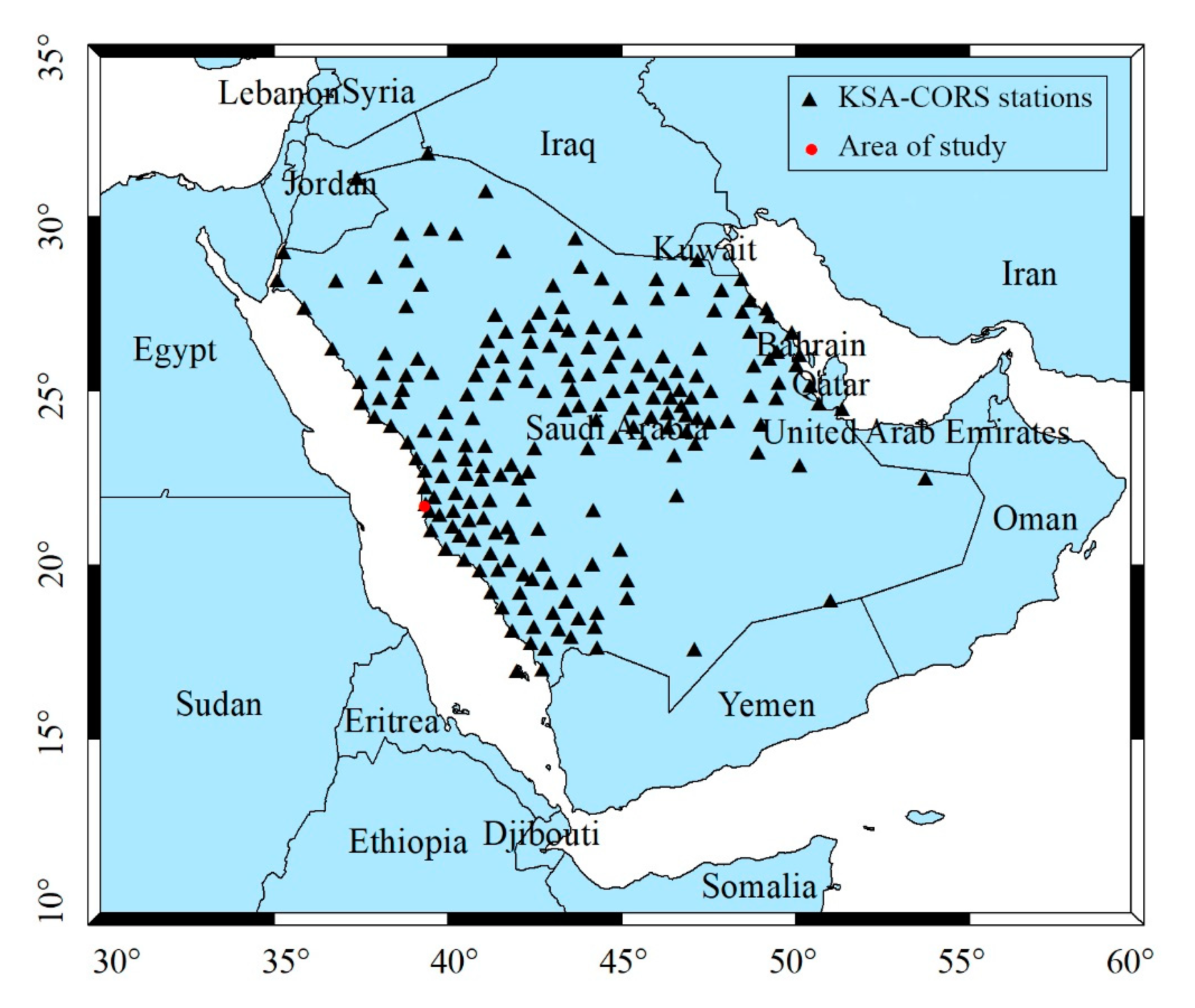
KSA Reference Network
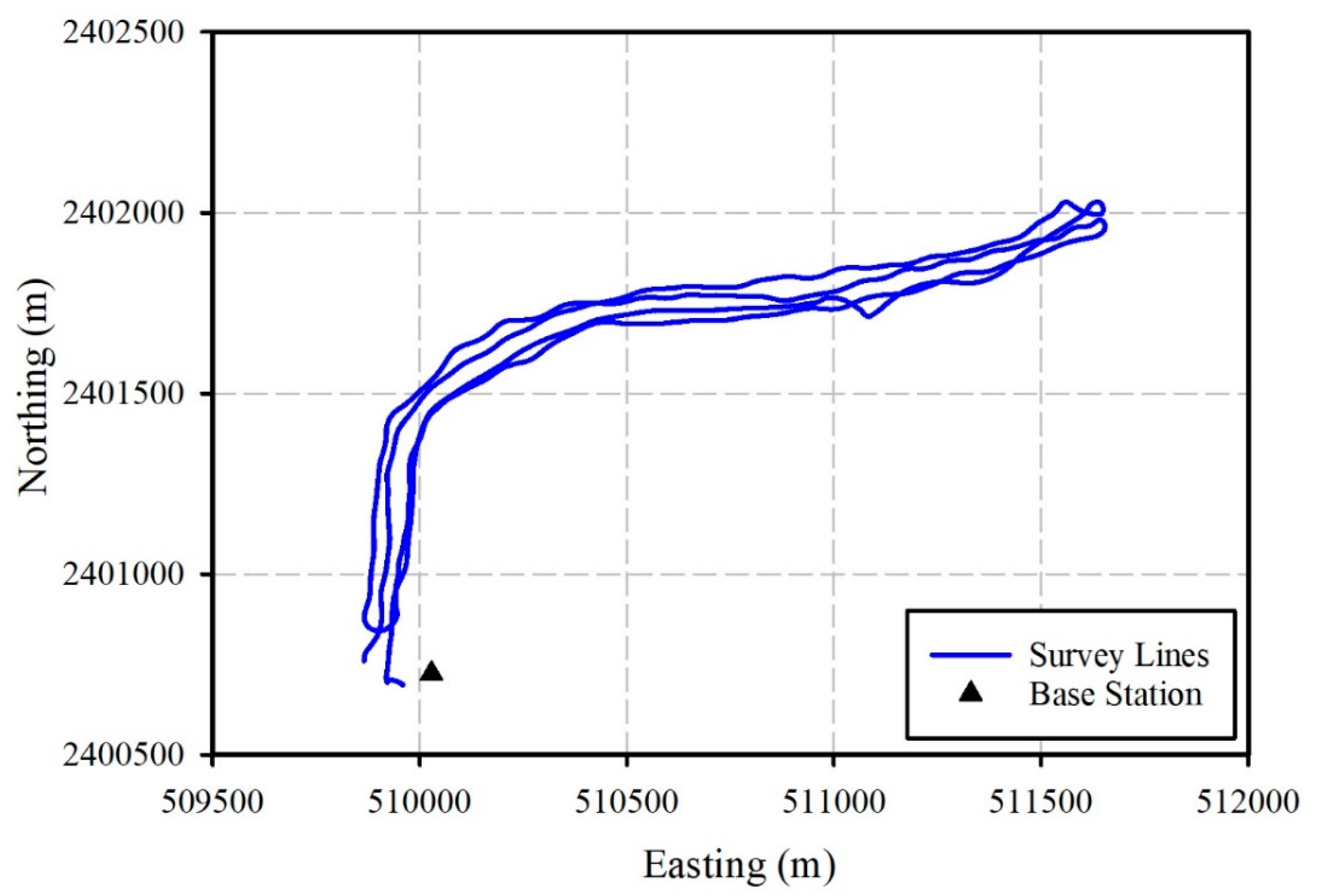
Kingdom of Saudi Arabia continuous operation reference station network (KSA-CORS) includes more than 200 GNSS stations. All stations are occupied with high end geodetic GNSS receivers. High rate GNSS data can be obtained from the web site of the general commission for survey (GCS) https://ksacors.gcs.gov.sa. KSA-CORS is used to generate 1 Hz GNSS data at a virtual location in the study area, which is denoted as VBase station (the VRS is chosen at the same location as the physical base station to maintain the same satellite geometry). Figure 3 shows the KSA-CORS network and the study area location is shown at the red dot.
The main objective of this paper is to evaluate the performance of satellite-based correction service, e.g., Trimble PP-RTX, and VRS techniques for bathymetry determination, and assess how far these techniques meet the minimum IHO standards for hydrographic surveys.

2. Field Test

KAU-Hydrography 1 vessel, Figure 4, was used to carry out a hydrographic surveying session of 3 h duration at Sharm Obhur where the Faculty of Maritime Studies (FMS) is located. The base station was setup on the rooftop of FMS main building using Trimble SPS855 GNSS receiver. Figure 5 shows the surveying lines and the base station location during the field test. The distance between the base station and the vessel was within 2.0 km. Kongsberg EM 712 multibeam echo sounder was used for bathymetry data collection. Valeport’s sound velocity profiler (SVP) was used to measure und velocity, temperature, and pressure through water layers. To obtain a robust and accurate position and orientation solution, Applanix POS MV was used to blend GNSS data with angular rate and acceleration data from an IMU and heading from GNSS Azimuth Measurement System (GAMS).

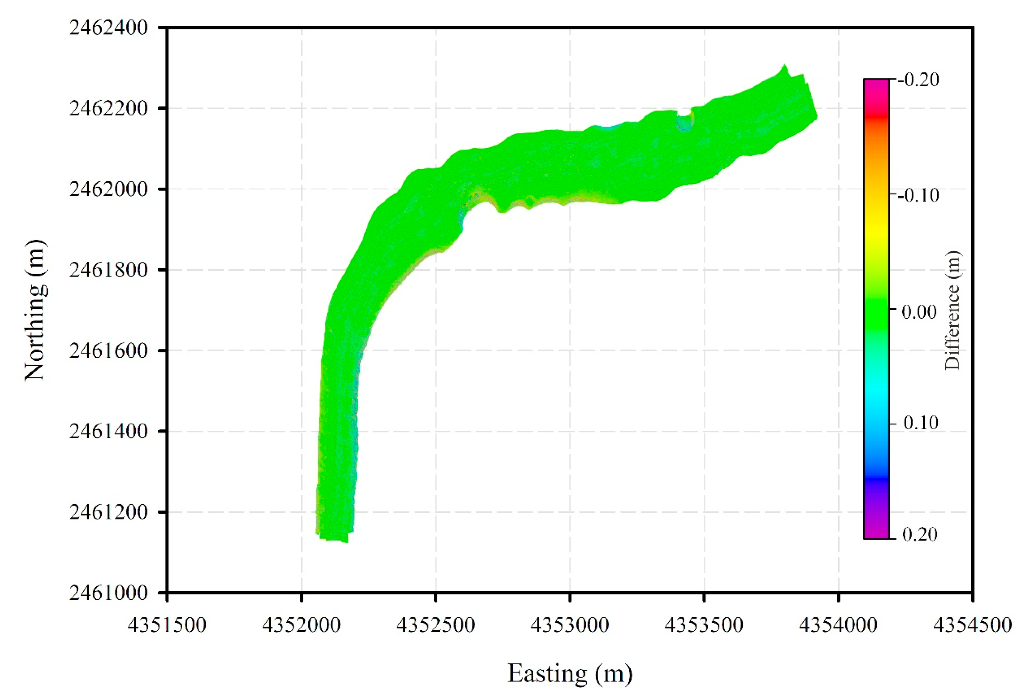
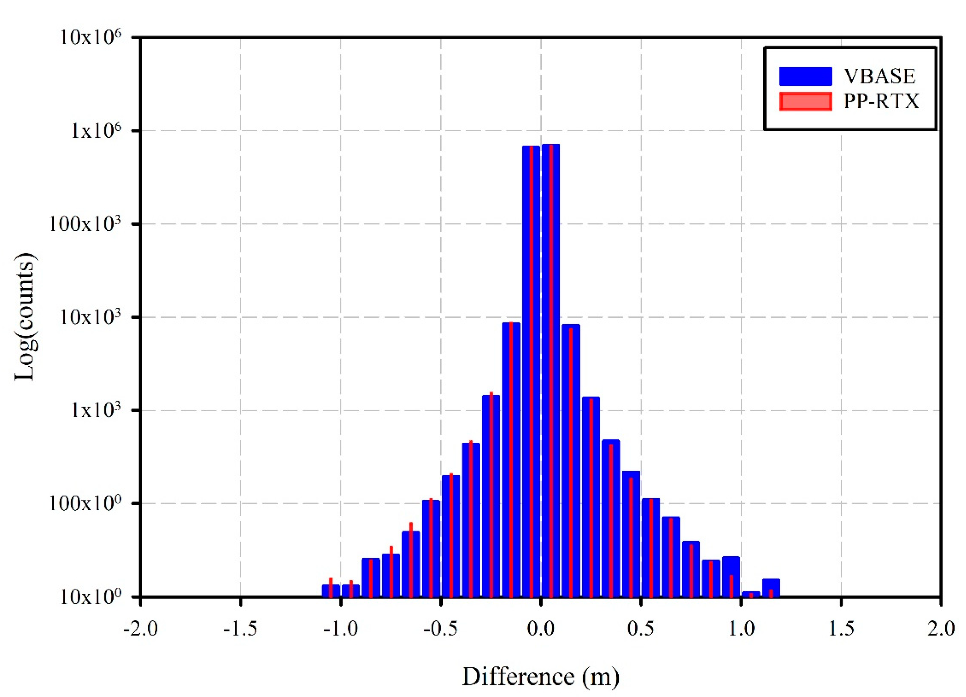
3. Data Processing and Results

Applanix POSPac MMS software was used to process GNSS data from the real base station and POS MV data to generate the smoothed best estimate of trajectory (SBET) file. The SBET generated using the real base station is used as a reference in this study. A second SBET file was generated using the PP-RTX corrections, while a third SBET was generated using the VBase GNSS data. Both PP-RTX and VBase trajectories were compared with the reference trajectory. Figure 6 shows the easting, northing, and up difference between Base and PP-RTX trajectories. Additionally, Figure 7 shows the differences between the Base and VBase trajectories.
To evaluate whether the PP-RTX and VBase solutions satisfy the IHO’s hydrographic surveys minimum standards, both the total horizontal uncertainty (THU) and the total vertical uncertainty (TVU) of both solutions were computed at 95% confidence level, as follows [24]:
T H U 95 % 2 D = 2.44 i = 1 n ( N ^ B a s e N ^ P P R T X V B a s e ) i 2 + ( E ^ B a s e E ^ P P R T X V B a s e ) i 2 n
T V U 95 % 1 D = 1.96 i = 1 n ( U ^ B a s e U ^ P P R T X V B a s e ) i 2 n
where T H U 95 % 2 D represents the total 2D horizontal uncertainty of northing and easting position error at 95% confidence level; N ^ B a s e ,   E ^ B a s e are the northing and easting coordinates of the real Base-based trajectory(the reference solution), respectively; N ^ P P R T X ,   E ^ P P R T X are the northing and easting coordinates of the PP-RTX-based trajectory; N ^ V B a s e ,   E ^ V B a s e are the northing and easting coordinates of the VBase-based trajectory; n is the total number of epochs; T V U 95 % 1 D represents the total 1D vertical uncertainty of the Up component at 95% confidence level.
Typically, the expected accuracy (RMS) using single base station is 0.8 mm + 1 PPM (part per million) for the horizontal component and 15 mm + 1 PPM for the vertical component [10]. That means that for a 2.0-km baseline, at one sigma level, 1.0 cm and 1.7 cm RMS is expected for horizonal and vertical components, respectively. Such accuracy must be considered and added to Equations (6) and (7) to compute THU and TVU at 95% confidence level. Table 1 summarizes the THU and TVU values at 95% confidence level estimated for both the PP-RTX and the VBase solutions.
Table 1 shows that both PP-RTX and VBase systems deliver comparable accuracies. Table 2 and Table 3, on the other hand, show the IHO minimum standards for hydrographic surveys. The values of THU and TVU in these tables are estimated as follows [25]:
T H U = c o n s t . + %   of   depth
T V U = ± a 2 + ( b × d ) 2
where a represents that portion of the uncertainty that does not vary with depth; b is a coefficient which represents that portion of the uncertainty that varies with depth; and d is the depth. The depth values used in Table 2 and Table 3 are 40 m for special order survey and 100 m for other survey orders.
Comparing THU and TVU of both techniques from Table 1 with the minimum IHO standards in Table 2 and Table 3, it is clear that both PP-RTX and VBase techniques meet the IHO minimum standards for all survey orders at 95% confidence level. To further investigate the difference between the surface generated using the PP-RTX technique and VBase technique, Caris HIPS and SIPS 11.00 was used to process the multibeam data and generate three gridded surfaces at a resolution of 0.50 m. Figure 8 shows the bathymetry of the survey area estimated using the first SBET file (the reference surface).
The main difference between the three surfaces is the source of the SBET file estimated earlier. Thus, at the end, we have the reference surface, the PP-RTX-based surface, and the VBase-based surface. Both PP-RTX surface and VBase surface are then compared with the reference surface using Caris HIPS and SIPS. Figure 9 shows the differences between the PP-RTX surface and the reference surface. Figure 10, on the other hand, shows the difference between the VBase surface and the reference surface.
Figure 9 and Figure 10 show that the main differences between the PP-RTX-based surface, the VBase surface, and the reference surface are at the channel edges beams. This is because of the slope is higher at channel edges and any horizontal shift in position will cause a significant change in depth. However, these differences are not significant and meet the IHO special order hydrographic survey standards. Table 4 summarizes the statistical analysis of the PP-RTX and VBase surface differences with the reference surface. Moreover, Figure 11 illustrates the statistical results of the PP-RTX and VBase surface differences.
Table 4, illustrating a statistical analysis of the seabed surface differences, shows a −0.07 cm average difference between the PP-RTX seabed surface and the reference seabed surface with a standard deviation of 3.60 cm. However, the average difference between the VBase seabed surface and the reference seabed surface is −0.03 cm and a standard deviation of 3.61 cm. It is clear from Table 4 and Figure 11 that both PP-RTX and VBase techniques could provide very accurate comparable results without the need for an existing real base station in the survey area.

4. Conclusions

This study aimed to evaluate the performance of a satellite-based correction service, e.g., Trimble PP-RTX, and a virtual GNSS reference station for bathymetry determination and assess how far these techniques meet the minimum IHO standards for hydrographic surveys. A three-hour duration session was conducted at Sharm Obhur using KAU-Hydrography 1 vessel. This session included GNSS data at a base station using Trimble SPS855 GNSS receiver, multibeam records using Kongsberg EM 712 multibeam echo sounder, sound velocity profile using Valeport’s sound velocity profiler, Applanix POS MV measurements, and real-time PP-RTX corrections.
Our results showed that THU and TVU of the PP-RTX technique are 5.50 cm and 5.90 cm at 95% confidence level, respectively. The THU and TVU of the VBase technique, on the other hand, are 5.75 cm and 7.05 cm at 95% confidence level, respectively. These results mean that both the PP-RTX and VBase techniques meet the IHO minimum standards of all hydrographic survey orders. Statistical analysis of the seabed surface differences showed a −0.07 cm average difference between the PP-RTX seabed surface and the reference seabed surface with a standard deviation of 3.6 cm. However, the average difference between the VBase seabed surface and the reference seabed surface is −0.03 cm and a standard deviation of 3.61 cm. From this study, we can conclude that both PP-RTX and VBase techniques meet the IHO standards for different hydrographic survey orders without the need for an existing real base station in the survey area.

Funding

This research was funded by Deanship of Scientific Research (DSR), King Abdulaziz University, Jeddah, grant number G-562-980-1441 and the APC was funded by DSR, King Abdulaziz University, Jeddah.

Acknowledgments

This work was funded by the Deanship of Scientific Research (DSR), King Abdulaziz University, Jeddah under grant no. (G-562-980-1441). The author, therefore, acknowledges with thanks DSR technical and financial support. The author acknowledges Trimble for providing access for PP-RTX corrections. The GNSS data used for VRS generation was obtained from the general commission for survey (GCS).

Conflicts of Interest

The author declares no conflict of interest.

References

  1. El-Rabbany, A. Introduction to GPS: The Global Positioning System, 2nd ed.; Artech House: Boston, MA, USA, 2006; p. 230. [Google Scholar]
  2. Hofmann-Wellenhof, B.; Lichtenegger, H.; Wasle, E. GNSS—Global Navigation Satellite Systems: GPS, GLONASS, Galileo, and More; Springer: Vienna, Austria; New York, NY, USA, 2008; p. 516. [Google Scholar]
  3. Luo, X. GPS Stochastic Modelling: Signal Quality Measures and ARMA Processes; Springer Science & Business Media: Berlin, Germany, 2013; p. 331. [Google Scholar]
  4. El-Rabbany, A. An Autonomous GPS Carrier-Phased-Based System for Precision Navigation. In Proceedings of the IEEE 2006 Intelligent Transportation Systems Conference (ITSC ‘06), Toronto, ON, Canada, 17–20 September 2006; pp. 783–787. [Google Scholar]
  5. Hutton, J.; Gopaul, N.; Zhang, X.; Wang, J.; Menon, V.; Rieck, D.; Kipka, A.; Pastor, F. Centimeter-level, robust gnss-aided inertial post-processing for mobile mapping without local reference stations. ISPRS Int. Arch. Photogramm. Remote Sens. Spat. Inform. Sci. 2016, XLI-B3, 819–826. [Google Scholar] [CrossRef]
  6. Zhang, F.; Brandl, M.; Chen, X.; Drescher, R.; Glocker, M.; Landau, H.; Leandro, R.; Nitschke, M.; Salazar, D.; Weinbach, U. Trimble CenterPoint RTX—A First Study on Supporting Galileo. In Proceedings of the European Navigation Conference, Vienna, Austria, 23–25 April 2013. [Google Scholar]
  7. Alkan, R.M. Cm-level high accurate point positioning with satellite-based GNSS correction service in dynamic applications. J. Spat. Sci. 2019, 1–9. [Google Scholar] [CrossRef]
  8. Leandro, R.; Landau, H.; Nitschke, M.; Glocker, M.; Seeger, S.; Chen, X.; Deking, A.; BenTahar, M.; Zhang, F.; Ferguson, K.; et al. RTX Positioning: The Next Generation of Cm-Accurate Real-Time GNSS Positioning. In Proceedings of the 24th International Technical Meeting of the Satellite Division of The Institute of Navigation (ION GNSS 2011), Portland, OR, USA, 20–23 September 2011; pp. 1460–1475. [Google Scholar]
  9. Trimble. Trimble RTX Frequently Asked Questions. Available online: https://positioningservices.trimble.com/wp-content/uploads/2019/02/Trimble-RTX-FAQ-2020-Brochure.pdf (accessed on 5 June 2020).
  10. Feld, C. What is the PP-RTX service and how to use it in POSPac. Applanix PP-RTX Technical Note. Available online: https://support.geocue.com/wp-content/uploads/2020/04/Applanix_TechNote_PPRTX.pdf (accessed on 5 June 2020).
  11. Hu, G.R.; Khoo, H.S.; Goh, P.C.; Law, C.L. Development and assessment of GPS virtual reference stations for RTK positioning. J. Geod. 2003, 77, 292–302. [Google Scholar] [CrossRef]
  12. Vollath, U.; Buecherl, A.; Landau, H.; Pagels, C.; Wagner, B. Multi-Base RTK Positioning Using Virtual Reference Stations. In Proceedings of the 13th International Technical Meeting of the Satellite Division of the Institute of Navigation (ION GPS 2000), Salt Lake City, UT, USA, 19–22 September 2000; pp. 123–131. [Google Scholar]
  13. Jin, S. Global Navigation Satellite Systems: Signal, Theory and Applications; Intech: Rijeka, Croatia, 2012; p. 426. [Google Scholar]
  14. Kleusberg, A.; Teunissen, P.J.G. GPS for Geodesy, 2nd ed; completely rev. and extended ed.; Springer: Berlin, Germany; New York, NY, USA, 1998; p. 650. [Google Scholar]
  15. Han, S.; Rizos, C. Instantaneous Ambiguity Resolution for Medium-Range GPS Kinematic Positioning Using Multiple Reference Stations; Springer: Berlin/Heidelberg, Germany, 1998; pp. 283–288. [Google Scholar]
  16. Gao, Y. Carrier phase based regional area differential GPS for decimeter-level positioning and navigation. In Proceedings of the 10th International Tech Meeting Satellite Division Inst Navigation, Kansas City, MO, USA, 16–19 September 1997; pp. 1305–1313. [Google Scholar]
  17. Gao, Y.; Li, Z. Ionosphere effect and modeling for regional area differential GPS network. In Proceedings of the 11th International Technical Meeting of the Satellite Division of The Institute of Navigation (ION GPS 1998), Nashville, TN, USA, 15–18 September 1998; pp. 91–98. [Google Scholar]
  18. Dai, L.; Han, S.; Wang, J.; Rizos, C. A study on GPS/GLONASS multiple reference station techniques for precise real-time carrier phase-based positioning. In Proceedings of the 14th International Technical Meeting of the Satellite Division of The Institute of Navigation (ION GPS 2001), Salt Lake City, UT, USA, 11–14 September 2001; pp. 392–403. [Google Scholar]
  19. Wanninger, L. Improved ambiguity resolution by regional differential modelling of the ionosphere. In Proceedings of the 8th International Technical Meeting of the Satellite Division of The Institute of Navigation (ION GPS 1995), Palm Springs, CA, USA, 12–15 September 1995; pp. 55–62. [Google Scholar]
  20. Wanninger, L. Enhancing differential GPS using regional ionospheric error models. Bull. Geod. 1995, 69, 283–291. [Google Scholar] [CrossRef]
  21. Wübbena, G.; Bagge, A.; Seeber, G.; Böder, V.; Hankemeier, P. Reducing distance dependent errors for real-time precise DGPS applications by establishing reference station networks. In Proceedings of the 9th International Technical Meeting of the Satellite Division of The Institute of Navigation (ION GPS 1996), Kansas City, MO, USA, 17–20 September 1996; pp. 1845–1852. [Google Scholar]
  22. Fotopoulos, G. Parameterization of Carrier Phase Corrections Based on a Regional Network of Reference Stations. Accepted for publication. In Proceedings of the 13th International Technical Meeting of the Satellite Division of the Institute of Navigation (ION GPS-00), Salt Lake City, UT, USA, 19–22 September 2000. [Google Scholar]
  23. Raquet, J.F. Development of a Method for Kinematic GPS Carrier-Phase Ambiguity Resolution Using Multiple Reference Receivers; UCGE Rep 20116, University of Calgary: Calgary, AB, Canada. Available online: http://hdl.handle.net/1880/25880:1998 (accessed on 10 May 2020).
  24. Elsobeiey, M. Performance Analysis of Low-Cost Single-Frequency GPS Receivers in Hydrographic Surveying. Int. Arch. Photogramm. Remote Sens. Spat. Inf. Sci. 2017, XLII-4/W5, 67–71. [Google Scholar] [CrossRef] [Green Version]
  25. International Hydrographic Bureau (IHO). IHO Standards for Hydrographic Surveys, Special Publication No. 44, 5th ed; February 2008; International Hydrographic Bureau: Monaco, 2008; Available online: https://iho.int/uploads/user/pubs/standards/s-44/S-44_5E.pdf (accessed on 15 May 2020).
Figure 1. PP-RTX implementation in POSPac MMS [10].
Jmse 08 00542 g001
Figure 2. Network of reference stations (R1, R2, R3), virtual station (V), and rover receiver (r).
Jmse 08 00542 g002
Figure 3. Saudi Arabia continuous operation reference station network (KSA-CORS).
Jmse 08 00542 g003
Figure 4. KAU-hydrography 1 vessel.
Jmse 08 00542 g004
Figure 5. Survey lines and base station location.
Jmse 08 00542 g005
Figure 6. Easting, northing, and up errors of the PP-RTX trajectory.
Jmse 08 00542 g006
Figure 7. Easting, northing, and up errors of the VBase trajectory.
Jmse 08 00542 g007
Figure 8. Bathymetry of the survey area using real base station.
Jmse 08 00542 g008
Figure 9. Difference between the PP-RTX-based surface and the reference surface.
Jmse 08 00542 g009
Figure 10. Difference between the VBase-based surface and the reference surface.
Jmse 08 00542 g010
Figure 11. Histogram of the PP-RTX and VBase surface difference.
Jmse 08 00542 g011
Table 1. Total horizontal uncertainty (THU) and total vertical uncertainty (TVU) of the PP-RTX and VBase solutions estimated at 95% confidence level.
PP-RTXVBase
THU (cm)5.505.75
TVU (cm)5.907.05
Table 2. International Hydrography Organization (IHO) minimum standards for hydrographic surveys (THU) [25].
Survey OrderSpecial1a1b2
Constant [m]25520
Varible
[% of depth]
05510
THU (m)2101030
Table 3. IHO Minimum standards for hydrographic surveys (TVU) [25].
Survey OrderSpecial1a1b2
Constant (a) [m]0.250.500.501.00
Varible (b)
[% of depth]
0.751.301.302.30
TVU (m)0.391.391.392.51
Table 4. Statistical analysis of surface differences.
PP-RTXVBase
Minimum (m)−3.82−4.76
Maximum (m)4.564.57
Mean (cm)−0.07−0.03
Standard Deviation (cm)3.603.61
Total Count1,375,3051,375,213

