Wave-Generated Current: A Second-Order Formulation

Aker Solutions, Oksenoyveien 8, 1366 Lysaker, Norway
J. Mar. Sci. Eng. 2020, 8(6), 418; https://doi.org/10.3390/jmse8060418
Submission received: 22 May 2020
/
Accepted: 6 June 2020
/
Published: 9 June 2020
(This article belongs to the Special Issue Selected Papers from the Future Paths and Needs in Wave Modelling Workshop)
Abstract
:In Stokes’ wave theory, wave numbers are corrected in the third order solution. A change in wave number is also associated with a change in current velocity. Here, it will be argued that the current is the reason for the wave number correction, and that wave-generated current at the mean free surface in infinite depth equals half the Stokes drift. To demonstrate the validity of this second-order formulation, comparisons to computational fluid dynamics (CFD) results are shown; to indicate its effect on wave loads on structures, model tests and analyses are compared.
1. Introduction
Within potential theory, waves do not create a current, and the widely used wave kinematics by Stokes [1] can be applied. However, as pointed out by Longuet-Higgins [2], vortices will diffuse from the boundaries and Stokes’ solution will no longer be valid. Here some examples from model tests and analyses are given that may support the suggestion in [3]; that waves in infinite water depth may create a shear current, which at the mean free surface, equals half the Stokes drift.
An apparently simple way of checking if waves create current is to look at the drift of a particle on the free surface, but unfortunately it has been difficult to find experimental results for such tests in the literature. The quote taken from a ResearchGate article [4] describes the lack of results: “Stokes drift has been as central to the history of wave theory as it has been distressingly absent from experiments”. Bremer and Breivik [5] summarized the works on Stokes drift, and explain that this test in a basin is indeed not simple, and that a large scatter in results has been seen over the years. Recently, Grue and Kolaas [6] did perform measurements of the drift with modern equipment, but their very steep waves and shallow water mean that the present theory needs to be extended in order to be fit for comparison.
On this technical note, Section 2 and Section 3 repeat previous results in order to explain why wave-generated current may exist. Section 4 describes theoretical viscous loads for a cylinder with and without a wave-generated current, and Section 5, Section 6, and Section 7 show comparisons to model tests, where it is argued that deviations may come from missing wave-generated current.
If wave-generated current exists, it influences the wave kinematics and hence the loads on offshore structures.
2. Theoretical Background
Third order kinematics for regular deep water waves—including the current term, are suggested in [3], where wave crests and particle velocities are both larger than the values for classical Stokes waves.
The argument in [3], for the existence of wave-generated current, is that the equation for Stokes third order wave number correction is identical to the linear wave-current interaction equation, if the current velocity equals half the Stokes drift.
The current, V, was found to be a shear current:
where the current at the mean free surface, z = 0, equals
which equals half the Stokes drift. k denotes the wave number, ω the angular frequency, A the wave amplitude and g the acceleration of gravity. The current gradient, β, can be written
The extension of the current down the fluid in (1) depends on the water depth. For infinite water depth, the minimum z-value can be set to the value where the current equals zero.
The derivation of the expression for Stokes drift can be found, for instance, in Neman’s book [7]. For irregular undisturbed waves generated in model test basins, the time series need to be low-pass filtered prior to establishing the wave-generated current. The cut-off frequency,, applied in the examples below is taken from DNVGL [8]; , where denotes significant wave height, and g the acceleration of gravity.
3. Comparison to CFD
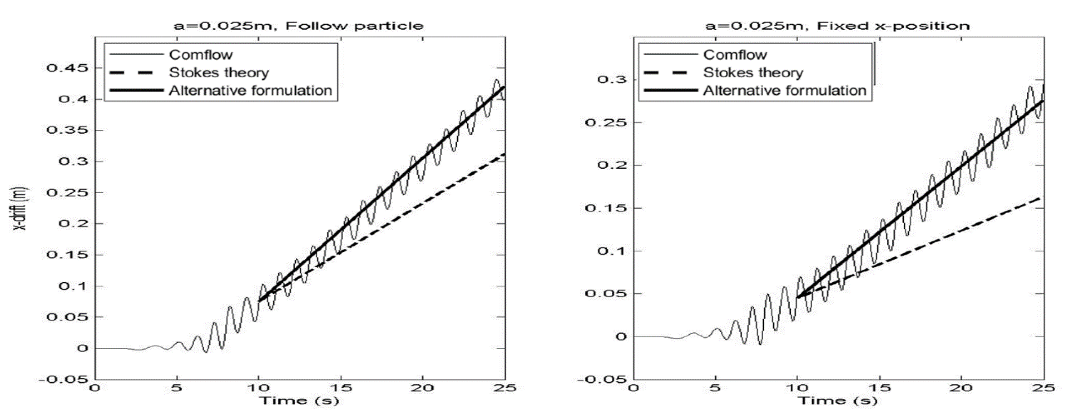
The results from the CFD program Comflow [9] are compared to the theory in [3], and they agree well, both for the actual drift, and for the mean velocity in a fixed horizontal position. The position is only fixed horizontally; vertically, it is free to move so that the point is always at the wave surface. This may be viewed in Figure 1, which is taken from [3]. In the right figure, the horizontal velocity is integrated with respect to time, in order to obtain similar plots. The Stokes drift increases by 50%, and the mean velocity in a fixed horizontal point by 100%, compared to Stokes theory. The simulated tank is 15 m × 0.1 m × 1.2 m, and an absorbing boundary is put at the outflow plane. The waves are created as ramped linear theoretic waves, and Comflow develops them into a proper shape. Sensitivity cases were not shown in [3], but, when creating the waves as fifth order, Stokes waves made no difference for the drift results, and convergence tests, with respect to the number of cells, showed very little difference.
4. Viscous Wave Loads on a Cylinder
The drag part of Morison’s equation is written:
where denotes horizontal wave particle velocity, and denotes the horizontal velocity of the structure. D is the structure diameter, the density of water and is the drag coefficient for the structure. For fixed cylinders, the integrated loads will always act in the wave direction, and the effect from the wave-generated current can be given as a ratio of the load neglecting this possible effect. Thus, wave-generated current can be neglected, as long as the drag coefficient is increased accordingly, which was the approach in [10]. In Figure 2, the horizontal mean load ratios for a fixed cylinder are plotted, with and without an original current. Because the extra current depends cubically on the wave number, it decreases if an original current is present. F_visc denotes the load in (4), with Stokes kinematics integrated over the wet cylinder and then averaged, and F_visc_WGC denotes the same, but with the wave-generated current included. Infinite water depth is assumed.
If the cylinder is free to move, the loads can change significantly. For cylinders following the waves, the drag loads can act in the opposite direction of the waves. Thus, the effect from wave-generated currents can change the sign, as well as the magnitude, of the loads. DNVGL [8] states that absolute, rather than relative, velocities should be applied in (4) for some sea states and structure diameters. Their argument is that too much damping will be present otherwise.
5. Model Tests and Analyses of a Semi-Submersible
In Figure 3, the low-frequency surge motion of a semi-submersible tested in an offshore basin is plotted, together with analysis results from the computer program Sima [11]. The waves are created by flaps in the tests, and Sima reads the undisturbed wave elevation from the tests. Sima includes second order drift coefficients, as well as viscous loads from slender elements. As is often the case for sea states without an original current, the largest low frequency peaks are under-estimated (e.g., [12]). The estimated wave-generated current is plotted in green (half of the Stokes drift). Although the mean wave-generated current is small, the largest current always acts at the same time as the critical waves and may influence the offset. Drift coefficients from potential theory, as well as viscous loads from Morison’s equation, are affected by the current. Unfortunately, Sima does not yet have the possibility of importing a time-dependent current, so investigations of the effect are not performed.
6. Model Tests and Analyses of a Spar
For spars, stick type structures with Morison loads up to the actual free surface are often applied in analyses. In this study, however, the analysis consisted of a panel model with drift coefficients, in addition to drag elements up to the free surface. Low frequency pitch was then under-estimated, as can be seen in Figure 4. The time instants for large wave-generated currents (half of the Stokes drift) coincide well with the time instants for large low frequency pitches in the tests. The computer program for the analysis was the same as for the semi-submersible above, i.e., it does not allow a time-dependent current. The model test basin was the same as well.
7. Comparison to Focused Waves
If [3] is wrong and wave-generated current does not exist, adding a current—which then would be artificial, in Stokes waves may simplify the third order wave number correction. Johannessen and Swans’ focused model test waves [13] show the importance of the distance from the wave maker and the wave number correction in the analyses.
For irregular waves, the higher order solution-including wave-generated current is still not established with all conditions satisfied, as was the case for regular waves. Therefore, only the linear term in the analyses is compared to the model test waves in Figure 5. The solution must be found by iteration, since the current depends on the wave numbers and the wave numbers depend on the current. In the figure below, four iterations were found to be sufficient for convergence.
8. Conclusions
Wave-generated current, with a magnitude equal to half of the Stokes drift at the mean free surface, is believed to be important for offshore structures, however, is missing in standard calculation tools. The examples presented in this document are for long-crested waves, and almost all of them are without current. Since wave-generated current acts in the wave direction, short-crestedness will decrease its effect, and if an original current is present, the effect will be smaller as well. Nevertheless, structures are often model tested in long-crested waves without current, and analysis models are established to best fit the results. Although deviations to model tests may be caused by other effects not captured in the analyses, the author believes that missing wave-generated current is an important reason, and encourages CFD users and basin owners to investigate whether or not waves create current. Depending on the outcome, software developers are encouraged to include time dependent current in their tools.
Conflicts of Interest
The authors declare no conflict of interest.
References
- Stokes, G.G. On the theory of oscillating waves. Camb. Trans. Philos. Soc. 1847, 8, 441–473. [Google Scholar]
- Longuet-Higgins, M.S. Mass transport in water waves. Philos. Trans. R. Soc. Lond. 1953, 245, 535–581. [Google Scholar]
- Bratland, A.K. The current generated by deep water regular waves. Coast. Eng. 2017, 121, 103–106. [Google Scholar] [CrossRef]
- Chafin, C. The absence of Stokes drift in waves. arXiv 2016, arXiv:1512.04132. [Google Scholar]
- Bremer, T.S.; Breivik, Ø. Stokes drift. Philos. Trans. R. Soc. Math. Phys. Eng. Sci. 2017, 376. [Google Scholar] [CrossRef] [Green Version]
- Grue, J.; Kolaas, J. Experimental Particle Paths and drift velocity in steep waves at finite water depth. Fluid Mech. 2017, 810. [Google Scholar] [CrossRef] [Green Version]
- Newman, J.N.N. Marine Hydrodynamics; MIT press: Cambridge, MA, USA, 1977. [Google Scholar]
- DNV GL. RP-C205: Environmental Conditions and Environmental Loads; DNV GL: Oslo, Norway, 2017. [Google Scholar]
- Van der Plas, P.; Veldman, A.E.P.; Seubers, H.; Helder, J.; Lam, K.W. Adaptive grid refinement for two-phase offshore applications. In Proceedings of the ASME 2018 37th International Conference on Ocean, Offshore and Arctic Engineering, Madrid, Spain, 17–22 June 2018. [Google Scholar]
- Kim, J.S.; Kim, H.; Lee, D.Y. Viscous Drift Forces on a Semi-Submersible in Combined wave and current. OMAE2018-77713, V001T01A003. In Proceedings of the ASME 2018 37th International Conference on Ocean, Offshore and Arctic Engineering, Madrid, Spain, 17–22 June 2018. [Google Scholar]
- SIMA. Available online: https://www.sintef.no/en/software/sima/ (accessed on 8 June 2020).
- Kvittem, M.I.; Berthelsen, P.A.; Eliassen, L.; Thys, M. Calibration of hydrodynamic coefficient for a semi-submersible 10MW wind turbine. OMAE2018-77826, V010T09A080. In Proceedings of the ASME 2018 37th International Conference on Ocean, Offshore and Arctic Engineering, Madrid, Spain, 17–22 June 2018. [Google Scholar]
- Johannessen, T.B.; Swan, C. A laboratory study of the focusing of transient and directionally spread surface water waves. Proc. R. Soc. Lond. A Math. Phys. Eng. Sci. Issue 2001, 457. [Google Scholar] [CrossRef]
Figure 1.
Comparisons of mean drift and velocity from Comflow (from 2015) and theories. Figure taken from [3].
Figure 1.
Comparisons of mean drift and velocity from Comflow (from 2015) and theories. Figure taken from [3].

Figure 2.
Calculated mean viscous drag load ratios for a fixed cylinder in infinite depth. Diameter = 15 m, draft = 30 m.
Figure 2.
Calculated mean viscous drag load ratios for a fixed cylinder in infinite depth. Diameter = 15 m, draft = 30 m.

Figure 3.
Left: Low frequency surge motion. Red—model tests, Blue: analyses; Right: Calculated wave-generated current.
Figure 3.
Left: Low frequency surge motion. Red—model tests, Blue: analyses; Right: Calculated wave-generated current.

Figure 4.
Left: Low frequency pitch, Red—Model tests, Blue—analyses; Right: Calculated wave-generated current.
Figure 4.
Left: Low frequency pitch, Red—Model tests, Blue—analyses; Right: Calculated wave-generated current.

Figure 5.
Comparison of model test waves from [13] (black), linear wave elevation with wave-generated current (magenta) and linear wave elevation from Stokes theory (blue); Wave-generated current (green) is plotted as well.
Figure 5.
Comparison of model test waves from [13] (black), linear wave elevation with wave-generated current (magenta) and linear wave elevation from Stokes theory (blue); Wave-generated current (green) is plotted as well.

© 2020 by the author. Licensee MDPI, Basel, Switzerland. This article is an open access article distributed under the terms and conditions of the Creative Commons Attribution (CC BY) license (http://creativecommons.org/licenses/by/4.0/).
Share and Cite
MDPI and ACS Style
Bratland, A.K. Wave-Generated Current: A Second-Order Formulation. J. Mar. Sci. Eng. 2020, 8, 418. https://doi.org/10.3390/jmse8060418
AMA Style
Bratland AK. Wave-Generated Current: A Second-Order Formulation. Journal of Marine Science and Engineering. 2020; 8(6):418. https://doi.org/10.3390/jmse8060418
Chicago/Turabian StyleBratland, Anne Katrine. 2020. "Wave-Generated Current: A Second-Order Formulation" Journal of Marine Science and Engineering 8, no. 6: 418. https://doi.org/10.3390/jmse8060418
Note that from the first issue of 2016, this journal uses article numbers instead of page numbers. See further details here.