Dimensioning of Fairway Bends—Kinematic Method of Numerical Simulation


Abstract
:1. Introduction
| dik(1-α) | – | safe manoeuvring area in i-th bend for k-th ship performing a simulated manoeuvre specified at the level of confidence 1-α; |
| Di(t) | – | available navigable area of i-th bend (the condition of safe depth at instant t is satisfied); |
| hxy(t) | – | water depth at point (x, y) at instant t; |
| Tk | – | maximum draft of k-th ship; |
| ∆ik(1-α) | – | underkeel clearance in i-th bend determined for k-th ship at the level of confidence 1-α. |
- real-time simulation of ship movement controlled by a human operator using non-autonomous simulation models;
- fast-time simulation of ship movement with a mathematical model of the navigator using autonomous simulation models;
- kinematic numerical simulation method determining a safe manoeuvring area based on multiple computer simulations of ship passage representing a wide set of physically possible ship movements in the bend.
- movement model on which the method is based refers to the centre of gravity, which means that the swept path of the ship is different from the path followed by its centre of gravity by an additional margins depending on the drift and parameters of the ship (e.g. breadth and length);
- tests are of a retrospective nature and start from the position in which the ship’s centre of gravity completes negotiating a bend;
- for sets of events to describe the entire physically possible movement and the movement model to be similar to reality, the arcs along which the ship’s centre of gravity moves have to result from the maximum rudder settings used in sea practice;
- the sector size is chosen so that it is equal to the ship track during the changes made in settings of the steering gear. The time is established as 10 seconds, which meets the classification society requirements referring to the rudder change from ‘midships’ to the maximum rudder angle in a fairway bend of 20°, recommended by international organisations [9,10];
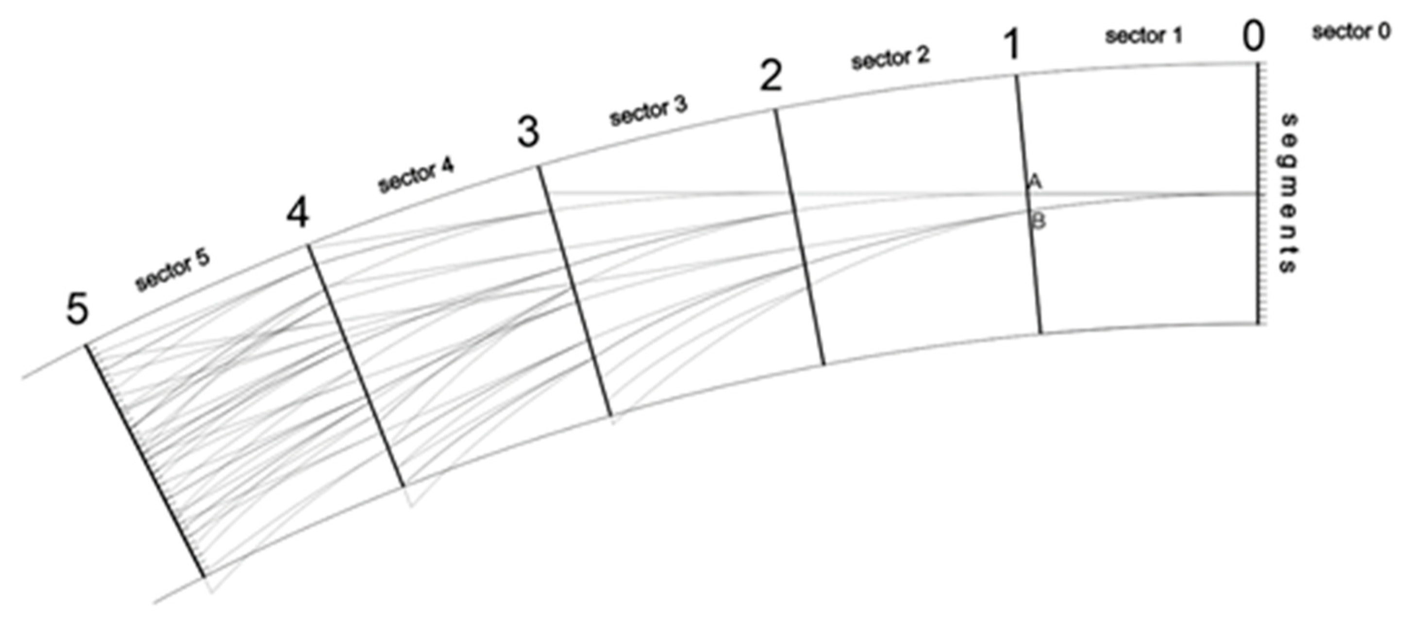
- For the sector 0 (end of the maneuver) it is assumed that the ship has a heading corresponding to the straight section of the fairway adjacent to the bend and the rate of turn (ROT) is 0 °/min.
- Because the ROT is 0 °/min in section 0, it is possible that the rudder angle is 0° or 10° in section 1. Hence, the positions of 2 points in section 1 can be determined (points A for rudder angle 0° and B for rudder angle 10° in the Figure 1).
- For each of these 2 points, possible paths in section 2 are determined. The number of possible points is 5, i.e. 2 for point A (rudder angle 0° and 10°) and 3 for point B (rudder angle 0°, 10° and 20°).
- The calculations are repeated until the last section of the bend. It is also checked whether the paths are in the assumed preliminary boundaries of the bend.
- parameters of the bend (angle of turn, arc radius),
- rudder deflection angle (10° or 20°),
- ship size and manoeuvring characteristics,
- initial ship speed,
- external conditions (wind, current, waves).
| ROT | – | ship’s ROT in the fairway bend [deg/min]; |
| ROTNOM | – | nominal ROT determined from manoeuvring data [deg/min]; |
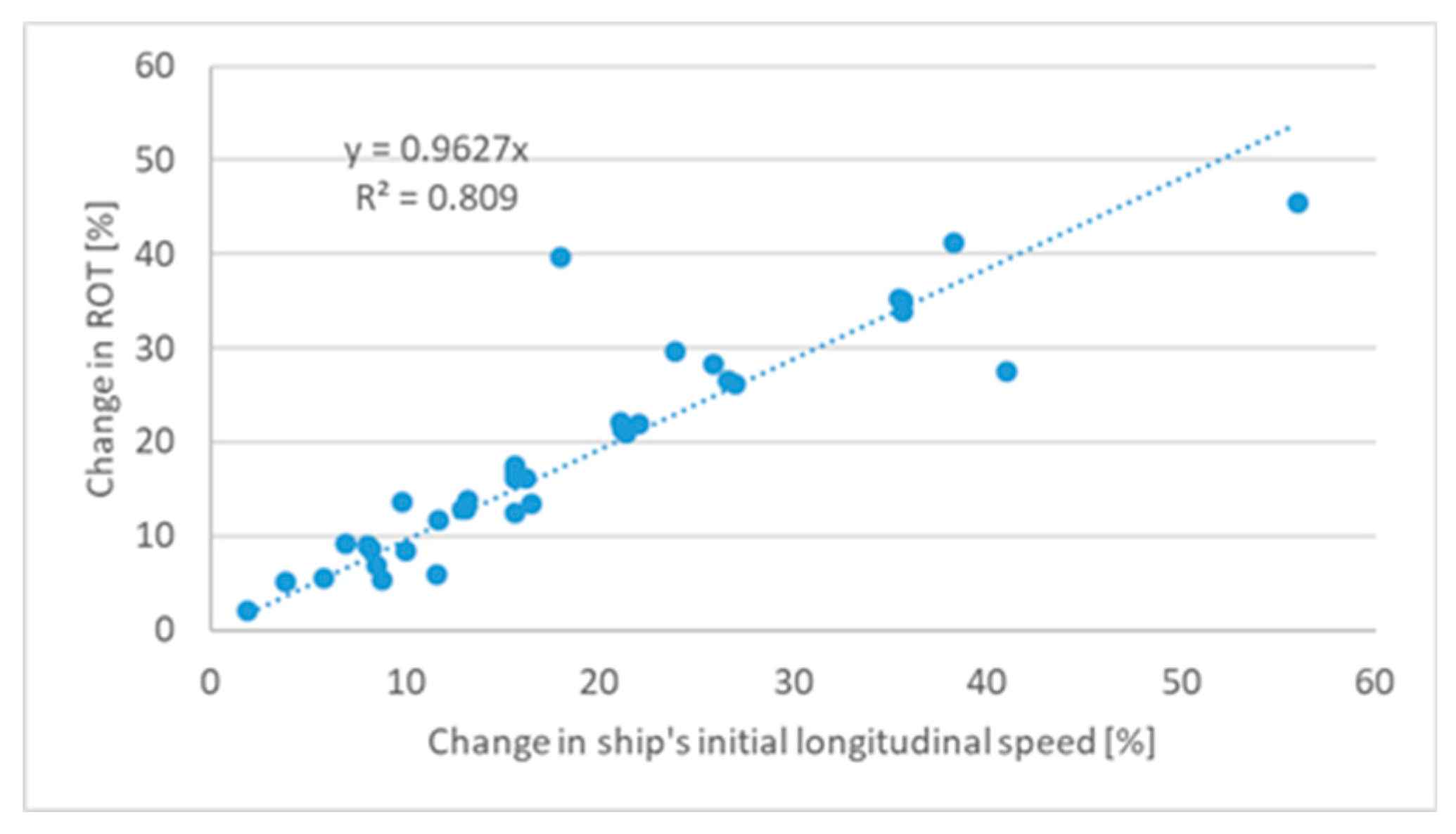
| ΔROTSOG | – | change in the ROT due to other than nominal initial longitudinal speed of the ship [deg/min]; |
| ΔROTα | – | change in the ROT due to the change in rudder angle [deg/min]. |
| ΔROTSOG | – | change in the ROT due to other than nominal initial longitudinal speed of the ship [deg/min]; |
| SOG | – | initial longitudinal speed of the ship [kts]; |
| SOGNOM | – | initial longitudinal speed adopted for the determination of ROTNOM [kts]; |
| ROTNOM | – | nominal ROT [deg/min]. |
2. The Kinematic Numerical Simulation Method of Dimensioning Safe Manoeuvring Areas in Fairway Bends
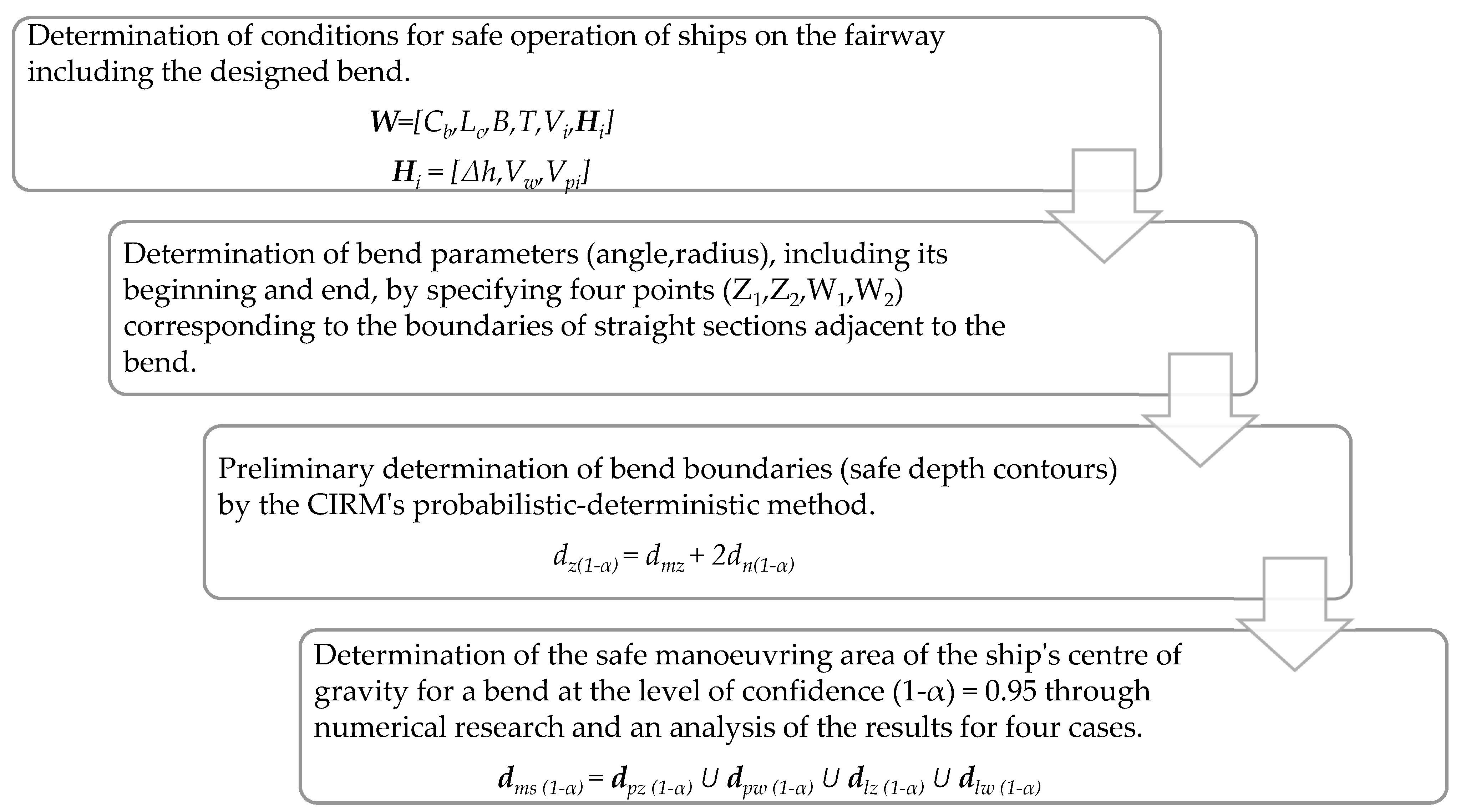
- Determination of the conditions for safe operation of ships on the fairway including the designed bend. These conditions are expressed as a set of conditions for safe operation of a ‘maximum ship’ i.e. a ship having the largest dimensions on the fairway:where
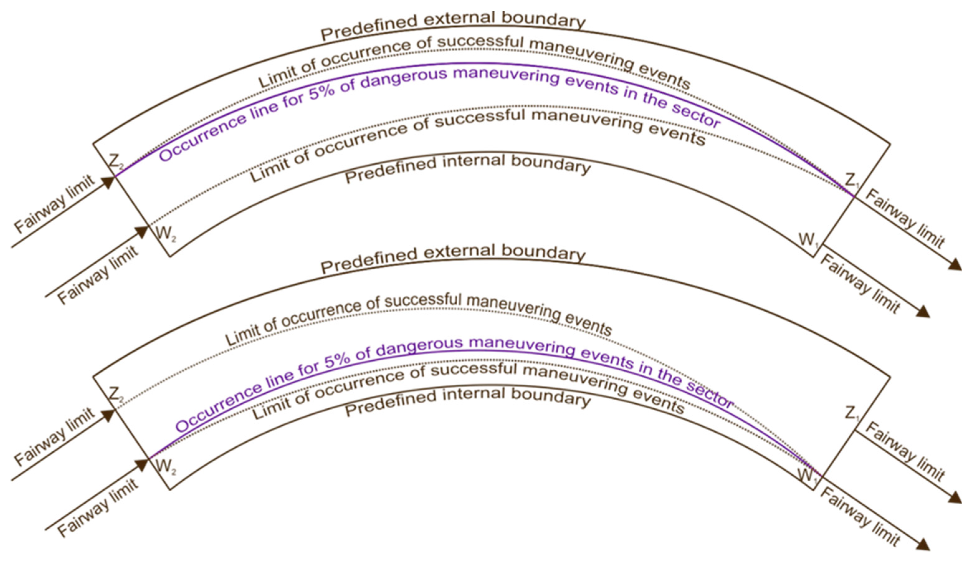
Cb – block coefficient that characterizes the type of the ‘maximum ship’ [-] Lc – length overall of the ‘maximum ship’ [m]; B – breadth of the ‘maximum ship’ [m]; T – draft of the ‘maximum ship’ [m]; Vi – speed of the ‘maximum ship’ in i-th section of the fairway [kts]; Hi – set of allowable hydrometeorological conditions for the passage of the ‘maximum ship’ along i-th section of the fairway. where∆h – allowable drop of water level on the fairway for the ‘maximum ship’ [m]; Vw – allowable speed of the ‘maximum ship’ entering the fairway [kts]; Vpi – allowable current speed for the ‘maximum ship’ in i-th section of the fairway [kts]. - The determination of the bend parameters, including its beginning and end, by specifying four points (Z1, W1, Z2, W2) corresponding to the boundaries of straight sections adjacent to the bend (Figure 5). Besides, the width of these straight sections is determined by the CIRM method at the confidence level (1-α) = 0.95 or it results from infrastructure restrictions in the area.
- Preliminary determination of bend boundaries (safe depth contours) by the CIRM’s probabilistic-deterministic method. The width of safe manoeuvring area in the bend for one-way traffic at the confidence level (1-α) = 0.95 is calculated from this relation [6]:where
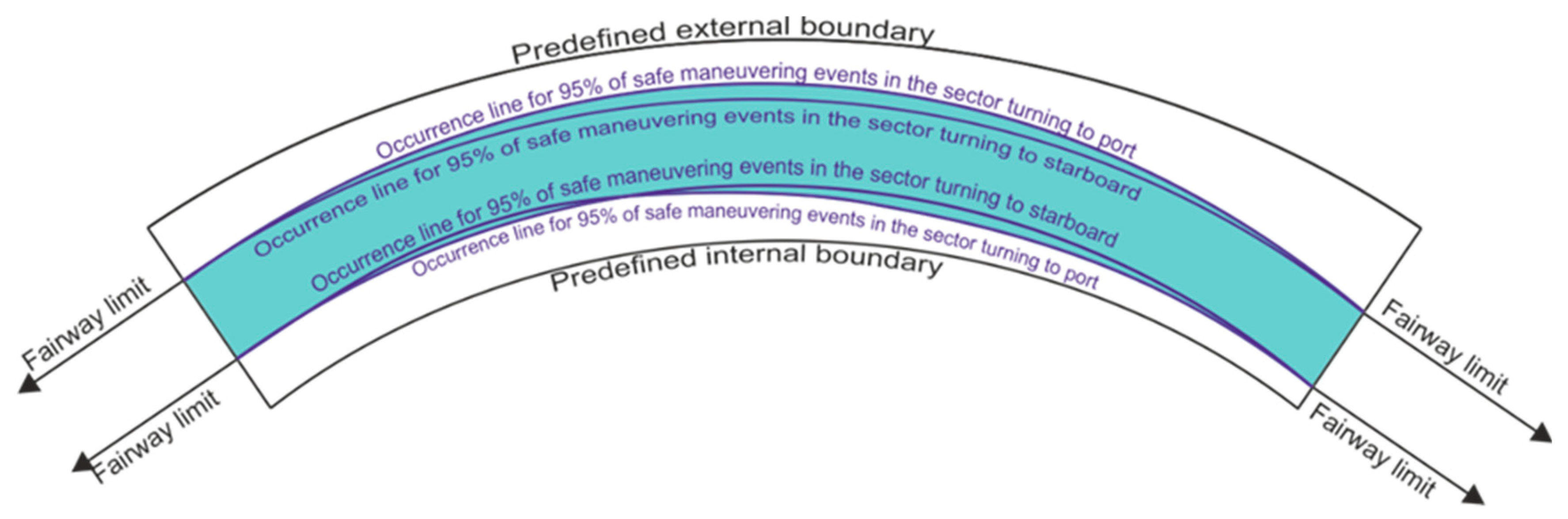
The manoeuvring component of safe manoeuvring area width is, respectively [8,15]:dz(1-α) – safe width of the manoeuvring area of the bend at the confidence level (1-α) [m]; dn(1-α) – navigational component of the width of the safe manoeuvring area of the bend at the confidence level (1-α) [m]; dmz – manoeuvring component of the safe manoeuvring area width of the bend [m]; wheredm – manoeuvring component of safe manoeuvring area width in a straight section of the fairway [m]; ∆d – widening of the vessel’s swept path in a bend [m]. - Determination of the safe manoeuvring area of the ship’s centre of gravity for a bend at the level of confidence (1-α) = 0.95 through numerical research and an analysis of the results for four cases, i.e., for both directions of passing through the bend and for two positions of the end of the turn determined by the boundaries of the manoeuvring areas of adjacent straight sections of the fairway determined at the confidence level (1-α) = 0.95 (Figure 5). The safe manoeuvring area of a ship’s centre of gravity in the bend is determined by adding four components of the manoeuvring areas of the ship’s centre of gravity calculated at the confidence level (1-α) = 0.95 (Figure 6) [7]:where
dpz (1-α) – manoeuvring area of the gravity centre of a ship turning right, completing the manoeuvre at a point of external boundary (Z1) of the adjacent manoeuvring area of a straight fairway section, (1-α) = 0.95; dpw (1-α) – manoeuvring area of the gravity centre of a ship turning right, completing the manoeuvre at a point of internal boundary (W1) of the adjacent manoeuvring area of a straight fairway section, (1-α) = 0.95; dlz (1-α) – manoeuvring area of the gravity centre of a ship turning left, completing the manoeuvre at a point of external boundary (Z2) of the adjacent manoeuvring area of a straight fairway section, (1-α) = 0.95; dlw (1-α) – manoeuvring area of the gravity centre of a ship turning left, completing the manoeuvre at a point of internal boundary (W2) of the adjacent manoeuvring area of a straight fairway section, (1-α) = 0.95;
- 5.
- The determination of the safe manoeuvring area of the bend for the ‘maximum ship’ at the confidence level (1-α) = 0.95 using the following relationship:where
An additional correction of the manoeuvring component is determined using the drift angle method.dms(1-α)(j) – width of the manoeuvring area of ship’s centre of gravity at j-th sector of the bend at the level of confidence (1-α) [m]; ∆dz – additional margin of the manoeuvring component of the bend width allowing for ship’s parameters (Lc, B) and its drift angle on the external part of the bend [m]; ∆dw – additional margin of the manoeuvring component of the bend width allowing for the ship’s parameters and its drift angle on the internal part of the bend [m].
3. Verification of the Kinematic Numerical Simulation Method of the Dimensioning of Safe Manoeuvring Areas in Fairway Bends
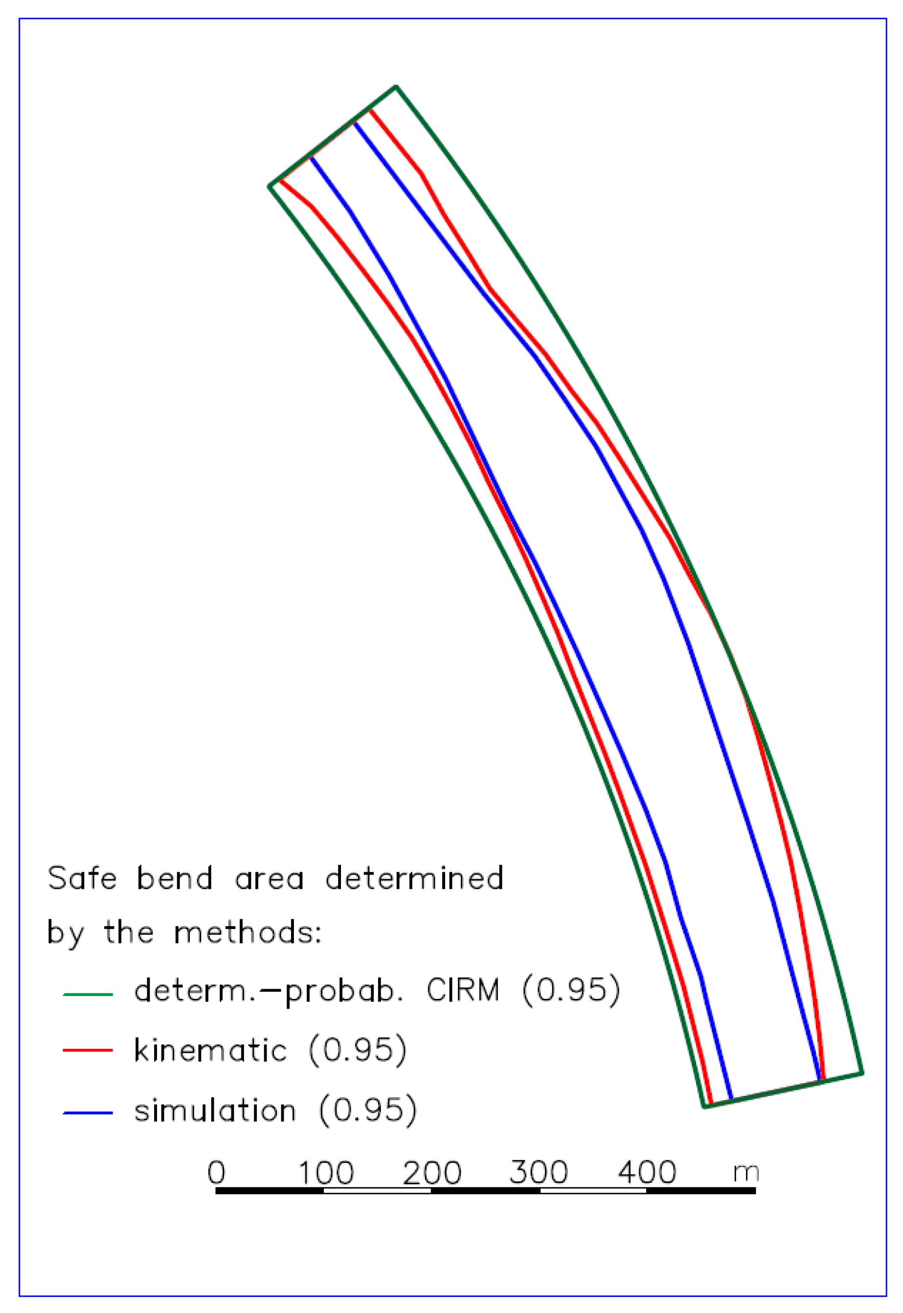
- Mańków bend (41.1 ÷ 42.3 km of the fairway)
- −
- turning angle ∆ψ = 26°
- −
- radius of arc Rz = 2200 m
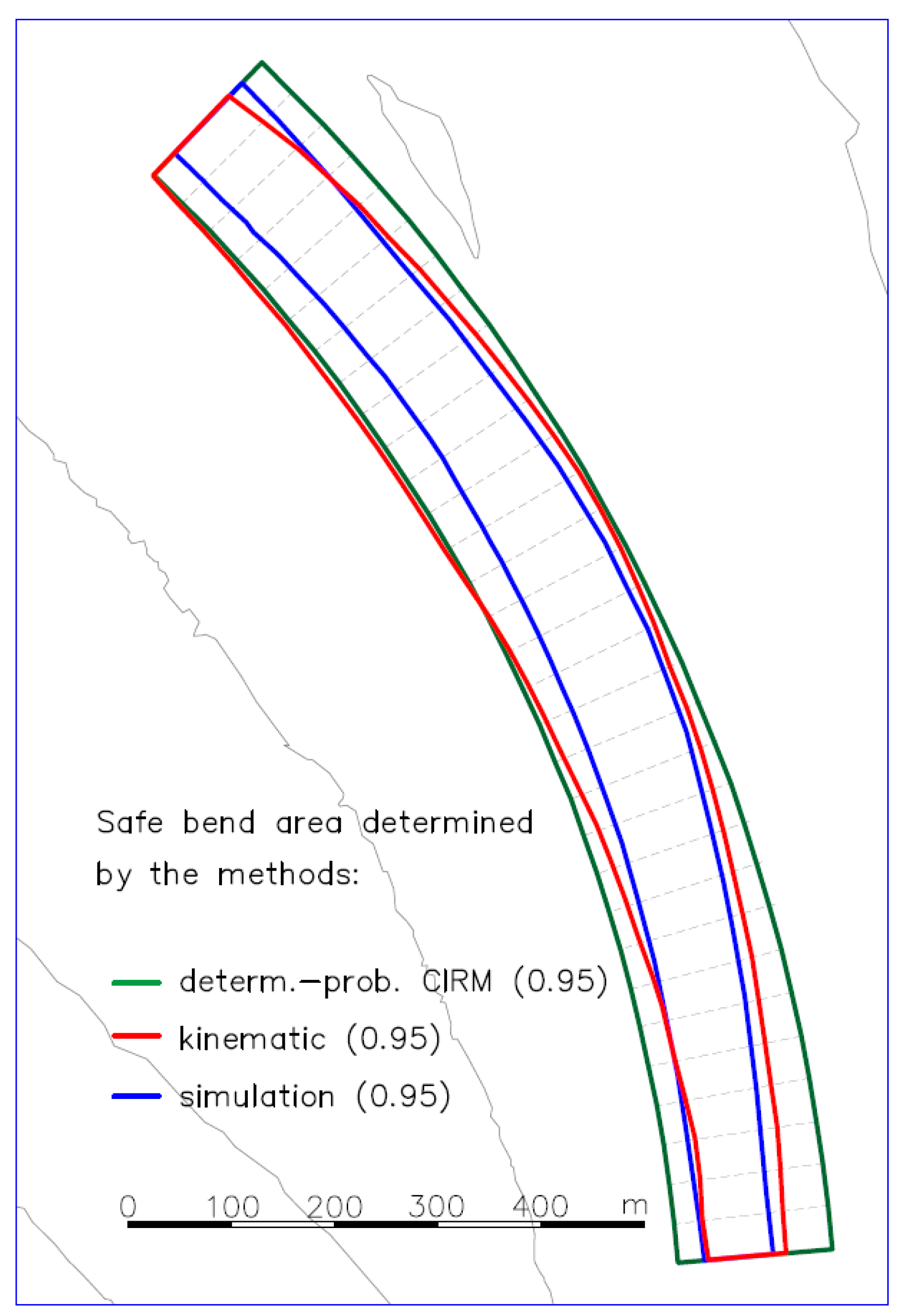
- Ińskie bend (51.7 ÷ 53.0 km)
- −
- turning angle ∆ψ = 42°
- −
- radius of arc Rz = 1860 m
| w | = | 47,000 t | – | displacement, loaded ship; |
| Lc | = | 195 m | – | length overall; |
| Lpp | = | 185 m | – | length between perpendiculars; |
| B | = | 29 m | – | breadth; |
| T | = | 11 m | – | draft; |
| AL | = | 1200 m2 | – | lateral windage area; |
- kinematic method of numerical simulation (described above);
- method of ship movement simulation, where the experiment was conducted on a full-mission bridge simulator Polaris from Kongsberg [16]. This simulator meets the Class A standards of marine simulator certification, which means hardware compliance with the requirements of the International Convention on Standards of Training, Certification and Watchkeeping (STCW). The simulator is used for trainings in accordance with the requirements of the STCW convention and recommendations of NI (Nautical Institute) and IMCA (International Marine Contractors Association). The number of simulation maneuvers in the test series was assumed to be equal to 12 for one wind direction. The tests were conducted for the two least favorable wind directions. Since no significant differences in the results were found, safe maneuvering areas were determined jointly for both directions of wind (with the number of trials being equal to 24). Approximately 10 pilots and experienced captains participated in the study. Each of them made several passages.
- Safe widths of the bend determined by a simulation experiment conducted on a Kongsberg-made full-mission bridge simulator at the Maritime University of Szczecin, with a participation of highly qualified pilots, who executed a reliable number of bend passages, can be regarded as model ones due to their high accuracy.
- The kinematic method, like the simulation method, estimates the safe bend width as a function of the turning angle. The CIRM method determines a safe width of the bend as a constant quantity (like the other empirical methods).
- The kinematic method overestimates the area of safe manoeuvring areas by approximately 40%, regardless of turning angles and bend radiuses.
- The CIRM method, one of the most accurate empirical methods, overestimates the area of safe manoeuvring areas by 60% for the turning angle of 26° and by 80% for the turning angle of 42°.
4. Summary
- The kinematic method of numerical simulation, like the ship movement simulation method, determines the width of the safe manoeuvring area of ships on the bend as a function of the turning angle. The CIRM method, like the other empirical methods, determines the width of the safe manoeuvring area of the bend as a constant quantity.
- The kinematic method of numerical simulation overestimates the manoeuvring area of the bend by approximately 40% (regardless of the turning angle) compared to the results obtained with real-time simulations, regarded as the reference method (the most accurate). This is related to the fact that the movement simulation involves the human factor. Officers navigating ships in restricted areas, especially with the use of leading lines, keep the ship exactly on the centerline of a traffic lane, which reduces its dimensions.
- The probabilistic-deterministic CIRM method overestimates the safe manoeuvring area of the bend compared to the ship movement simulation method by approximately 60% for the turning angle of 26° and by 80% for the turning angle of 42° (this is one of the most accurate empirical methods).
- The costs of the kinematic method of numerical simulation are significantly lower than the costs of ship movement simulation and comparable to the costs of empirical methods.
- The computer program created allows the results to be obtained within a limited period of time. Single calculations using a computer equipped with the 8th-generation i7 processor and 12 GB RAM took less than an hour.
- the method overestimates the area of safe manoeuvring areas of the bend by approximately 40% compared to the ship movement simulation method, regardless of the turning angle. At the same time the kinematic method maintains the dependence of the safe manoeuvring area width on the current angle of turn.
- the kinematic method of numerical simulation is much more accurate than the empirical methods in use.
Author Contributions
Funding
Conflicts of Interest
References
- UNCTAD. Handbook of Statistics; United Nations Publications: New York, NY, USA, 2019. [Google Scholar]
- Gucma, S. Sea Waterways. In Design and Operation in Terms of Traffic Engineering; Fundacja Promocji Przemysłu Okrętowego i Gospodarki Morskiej: Gdańsk, Poland, 2015. (In Polish) [Google Scholar]
- Gucma, S.; Gucma, L.; Zalewski, P. Simulation Research Methods in Maritime Traffic Engineering; The Maritime University of Szczecin Press: Szczecin, Poland, 2008. [Google Scholar]
- PIANC. Harbour Approach Channels—Design Guidelines, Report n° 121; PIANC: Brussels, Belgium, 2014. [Google Scholar]
- Puertos Del Estado. ROM 3.1-99, Design of the Maritime Configuration of Ports, Approach Channels and Harbour Basins; Spanish National Ports & Harbours Authority: Madrid, Spain, 2007. [Google Scholar]
- Gucma, S. Maritime Traffic Engineering—Guidelines for the Design of Maritime Waterways and Ports and the Conditions for Their Safe Operation; Fundacja Promocji Przemysłu Okrętowego i Gospodarki Morskiej: Gdańsk, Poland, 2017. (In Polish) [Google Scholar]
- Gucma, S.; Dzwonkowski, J.; Przywarty, M. Kinematic method of determining safe fairway bend widths. IJMNSST. in press.
- Dzwonkowski, J. A Kinematic Method for Determining Safe Bend Parameters on Fairways. Ph.D. Thesis, Maritime University of Szczecin, Szczecin, Poland, 2018. (In Polish). [Google Scholar]
- PIANC. Workshop on Design Guidelines for Inland Waterways. Smart Rivers; PIANC: Brussels, Belgium, 2014. [Google Scholar]
- PRS. Rules for the Classification and Construction of Sea-Going Ships Part III Hull Equipment; PRS: Gdańsk, Poland, 2013. (In Polish) [Google Scholar]
- Nowicki, A. Knowledge about Sea Vessels Manoeuvring; Trademar: Gdynia, Poland, 1999. (In Polish) [Google Scholar]
- Eloot, K.; Delefortrie, G.; Mostaert, F. Manoeuvring Characteristics: Sub Report 7—Comparison of the Manoeuvring Characteristics of the COSCO 20,000 TEU and Other Ultra Large Container Ships; Flanders Hydraulics Research: Antwerp, Belgium, 2018. [Google Scholar]
- Fossen, T. Handbook of Marine Craft Hydrodynamics and Motion Control; John Wiley & Sons Ltd.: Hoboken, NJ, USA, 2011. [Google Scholar]
- Przywarty, M.; Gucma, L.; Perkovic, M. Influence of speed reduction on navigational safety of container ships. SJMUS 2013, 108, 125. [Google Scholar]
- Canadian Coast Guard. Canadian Waterways National Manoeuvring Guidelines—Channel Design Parameters; Department of Fisheries and Oceans: Ottawa, ON, Canada, 1999. [Google Scholar]
- MUS. Navigational Analysis of the Modernization of the Świnoujście—Szczecin Fairway (Dredging to 12.5 m); Europrojekt Gdańsk, S.A., Ed.; Maritime University of Szczecin: Szczecin, Poland, 2015. [Google Scholar]
- Gucma, S. Optimization of parameters of the system of dredged sea waterways to a given depth on the example of the reconstruction of the Świnoujście—Szczecin fairway. AoT 2016, 40, 29–38. [Google Scholar] [CrossRef]


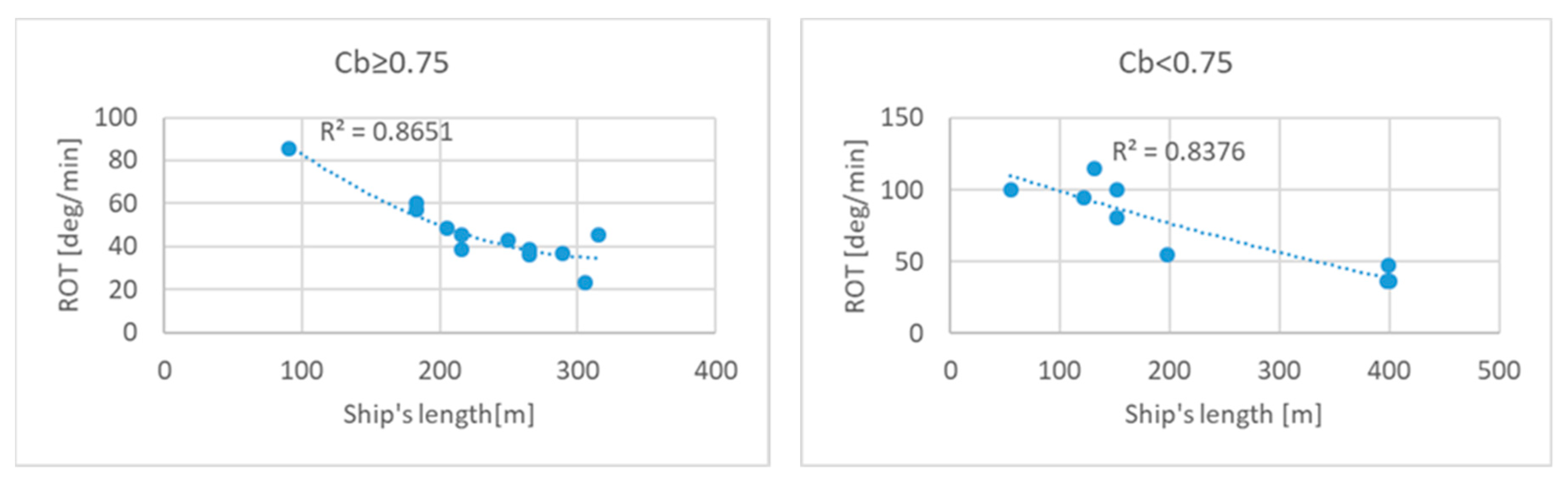
| Ship’s Length [m] | ROTNOM [deg/min] | |
|---|---|---|
| Cb ≥ 0.75 | Cb < 0.75 | |
| 60 | 101.362 | 108.722 |
| 80 | 91.626 | 103.846 |
| 100 | 82.610 | 99.050 |
| 120 | 74.314 | 94.334 |
| 140 | 66.738 | 89.698 |
| 160 | 59.882 | 85.142 |
| 180 | 53.746 | 80.666 |
| 200 | 48.330 | 76.270 |
| 220 | 43.634 | 71.954 |
| 240 | 39.658 | 67.718 |
| 260 | 36.402 | 63.562 |
| 280 | 33.866 | 59.486 |
| 300 | 32.050 | 55.490 |
| Rudder Deflection Angle [deg] | k |
|---|---|
| >=35 | 0 |
| 30 | 0.09 |
| 25 | 0.24 |
| 20 | 0.29 |
| 15 | 0.39 |
| 10 | 0.50 |
| 5 | 0.57 |
| Method of Calculations | Mańków Bend • Turning Angle: 26° • Radius: 2200 m | IńSkie Bend • Turning Angle: 42° • Radius: 1860 m |
|---|---|---|
| simulation method of ship movement | 81,956 m2 | 107,163 m2 |
| kinematic method of numerical simulation | 114,764 m2 | 148,790 m2 |
| probabilistic-deterministic CIRM method | 148,004 m2 | 188,007 m2 |
© 2020 by the authors. Licensee MDPI, Basel, Switzerland. This article is an open access article distributed under the terms and conditions of the Creative Commons Attribution (CC BY) license (http://creativecommons.org/licenses/by/4.0/).
Share and Cite
Gucma, S.; Przywarty, M.; Dzwonkowski, J.; Bilewski, M. Dimensioning of Fairway Bends—Kinematic Method of Numerical Simulation. J. Mar. Sci. Eng. 2020, 8, 138. https://doi.org/10.3390/jmse8020138
Gucma S, Przywarty M, Dzwonkowski J, Bilewski M. Dimensioning of Fairway Bends—Kinematic Method of Numerical Simulation. Journal of Marine Science and Engineering. 2020; 8(2):138. https://doi.org/10.3390/jmse8020138
Chicago/Turabian StyleGucma, Stanisław, Marcin Przywarty, Jan Dzwonkowski, and Mateusz Bilewski. 2020. "Dimensioning of Fairway Bends—Kinematic Method of Numerical Simulation" Journal of Marine Science and Engineering 8, no. 2: 138. https://doi.org/10.3390/jmse8020138