Article

Predicting the Deflection of Square Plates Subjected to Fully Confined Blast Loading

1
Key Laboratory of High Performance Ship Technology, Wuhan University of Technology, Ministry of Education, Wuhan 430063, China
2
Green and Smart River-Sea-Going Ship, Cruise Ship and Yacht Research Center, Wuhan University of Technology, Wuhan 430063, China
3
Department of Naval Architecture, Ocean and Structural Engineering, School of Transportation, Wuhan University of Technology, Wuhan 430063, China
4
Department of Mechanical Engineering, Imperial College London, South Kensington, London SW7 2AZ, UK
*
Authors to whom correspondence should be addressed.
J. Mar. Sci. Eng. 2020, 8(12), 1031; https://doi.org/10.3390/jmse8121031
Submission received: 19 November 2020 / Revised: 13 December 2020 / Accepted: 15 December 2020 / Published: 18 December 2020
(This article belongs to the Special Issue Accidental Limit States of Marine Structures)

Abstract

:
The main objective of this study is to conveniently and rapidly develop a new dimensionless number to characterize and predict the deflection of square plates subjected to fully confined blast loading. Firstly, based on the Kirchhoff–Love theory and dimension analysis, a set of dimensionless parameters was obtained from the governing equation representing the response of a thin plate subjected to impact load. A new dimensionless number with a definite physical meaning was then proposed based on dimensional analysis, in which the influence of bending, torsion moment and membrane forces on the dynamic response of the blast-loaded plate were considered along with the related parameters of the blast’ energy, the yield strength of the material, the plate thickness and dimensions of the confined space. By analyzing the experimental data of plates subjected to confined blast loading, an approximately linear relationship between the midpoint deflection–thickness ratio of the target plate and the new dimensionless number was derived. On this basis, an empirical formula to predict the deflection of square plates subjected to fully confined blast loading was subsequently regressed, and its calculated results agree well with the experimental data. Furthermore, numerical simulations of square plates subjected to blast loading in a cuboid chamber with different lengths were performed. The numerical results were compared with the calculated data to verify the applicability of the present empirical formula in different scenarios of blast loading from explosions in a cuboid space. It is indicated that the new dimensionless number and corresponding empirical formula presented in this paper have good applicability and reliability for the deflection prediction of plates subjected to fully confined explosions in a cuboid chamber with different lengths, especially when the plates experience a large deflection–thickness ratio.

1. Introduction

Confined explosions can occur due to possible deliberate attacks in a subway station, an accidental explosion inside an ammunition storage facility or an explosion of a missile in a naval vessel [1,2,3]. A typical confined blast load consists of several shockwaves and a relatively long duration of gas pressure load [3,4,5]. Thus, the confined explosion usually causes more severe damage than that caused by an external free-air explosion from the same explosive mass [3,6]. The confinement effects of blast load, dynamic responses and failure mechanism of a structure subjected to confined blast loading, such as metal containers, pipes and explosion containment vessels, has recently received considerable attention, and abundant research has been reported [7,8,9,10,11,12,13,14]. In addition, research related to the dynamic response of metal plates subjected to confined blast loading has also been conducted. Geretto et al. [6] conducted experiments to investigate the plastic deformations of square plates subjected to fully confined blast loading, in which the effects of plate thickness, charge mass and confinement degree on the dynamic response of plates were studied. Zilliacus et al. [15] conducted a series of confined explosion tests for 12-inch-diameter steel and aluminum plates. Pressure histories, deformation shapes and failure modes of plates with different thicknesses were recorded, and a tentative empirical law governing the final deformation of a blast-loaded plate was developed. In our previous work, a cuboid chamber was designed to produce replicated confined blast loading on square steel plates with different thicknesses and stiffener configurations. The plastic deformations of plates subjected to confined blast loading were recorded, and the effects of venting, plate thickness and stiffener configuration were investigated [16]. From a numerical computation perspective, Kong et al. [1] conducted numerical studies on a multilayer protective structure under confined blast loading, in which the interaction between the blast wave and steel bulkheads was presented. Zheng et al. [17] studied the interaction between a reflected blast wave and steel plates under confined blast loading through numerical modeling based on the fully coupled Euler–Lagrange method in the commercial code AUTODYN. The influence of the stiffener on the dynamic response of stiffened plates under confined blast loading was investigated in Zhao’s study through numerical simulations [18]. Rabczuk et al. [19,20,21] developed numerical methods to deal with the fluid–structure interaction of fracturing structures under impulsive loads, which is useful for the numerical simulation of the dynamic response of plates under extreme loads.
Issues with respect to blast loadings and the dynamic response of structures are incredibly complicated and influenced by many factors. Experimental and numerical methods are appropriate research tools for determining structural impact response; however, time and costs are huge. Empirical modeling has frequently been used to analyze the dynamic response of structures under impact loads. From an empirical modeling perspective, dimensional analysis is an effective method to determine dominating parameters and their interrelationship, through which these parameters can be particularly combined to simplify the problem [22,23]. Many scholars have presented dimensional analysis on the dynamic response of structures under impact or blast loading [24,25,26,27,28]. Dimensionless numbers obtained from the dimensional analysis are useful for organizing experimental tests, results analysis and structural response prediction. Johnson [24] used a damage number D n to identify various impact regions in metals. Jones [25] developed a complete set of dimensionless numbers using the Buckingham Π theory for analyzing structural mechanics, in which several important parameters involved in the dynamic response were considered. The damage number based on the impulse was suggested for the dynamic response analysis of beams and plates. Zhao et al. [28] studied the dynamic response of a fully clamped perfectly elastic plastic beam under uniformly distributed impulsive loads, and a dimensionless number R n , which considered the geometric parameter L / H , was proposed for impact-loaded beams and plates. Nurick and Martin [27] improved Johnson’s damage number by taking the parameters of the width and length of the plate into account in their study of quadrangular plates subjected to uniform impact load, noted as ϕ q . Furthermore, the relationship between the midpoint deflection–thickness ratio and the dimensionless number ϕ q was investigated. Jacob et al. [29] tested fully clamped circular plates subjected to blast loading detonated at various stand-off distances. In order to weigh the effect of stand-off distance on plate response, a stand-off distance parameter ζ s was introduced to modify the dimensionless number ϕ c proposed by Nurick and Martin [27].
For the above-mentioned dimensionless numbers, the blast load was mostly characterized as an impulse, which can be easily determined by employing empirical formulas. However, in confined blast scenarios, it is difficult to determine the effective impulse applied on plates due to the complexity of the blast load consisting of multireflected shockwaves and long-lasting quasistatic pressure varying in different confined spaces. Geretto et al. [6] used the impulse of the unconfined blast and the ratios of midpoint deflections of a plate subjected to unconfined and fully confined blast loading to obtain an equivalent impulse for a fully confined blast. The relationship between the normalized midpoint deflection–thickness ratio and dimensionless number ϕ q was consistent with the results specified by the authors of [27]. However, in practice, the impulse of a free-air blast with the same charge and stand-off distance as a confined blast cannot always be easily and conveniently obtained.
In the current study, based on general dimensional analysis, a new dimensionless number with a wide scope of application was suggested for the dynamic response analysis of plates subjected to confined blast loading, which considers the influence of the blast energy, the strength of the material, the geometry of the confined chamber, the plate thickness and other structural dimensions. The validity and efficiency of the newly suggested dimensionless number were discussed. In addition, an empirical formula was obtained, which can be applied to predict the residual deflection of plates subjected to blast loading from a confined explosion in a cubic or cuboid chamber.

2. New Dimensionless Number for Analysis of Plates under Confined Blast Loading

The issues with regard to the dynamic response of structures under confined blast loading are very complicated and related to many influence factors. In this section, a new dimensionless number was obtained based on the dimensionless governing equations of square plates due to dynamic loads. Appropriate input and output dimensionless parameters are proposed for predicting the midpoint deflections of square plates under a confined explosion in a fully confined chamber. All the parameters in the new dimensionless number have a definite physical meaning.

2.1. Confined Explosion in a Cubic Chamber

Firstly, the dynamic response of square plates under a confined explosion in the specific cuboid chamber, with the same length, width and height, was chosen as the research object. Classical plate theory was employed to derive the appropriate dimensionless parameters for estimating the midpoint deflections of the blast-loaded square plates. When subjected to blast loading, the target plates usually experienced large deflections compared to the plate thicknesses, and the membrane forces were subsequently induced. Therefore, the effect of the membrane forces should be taken into consideration in the analysis. Assuming that the plate is inextensible in the transverse direction and the transverse shear deformations are negligible, according to the Kirchhoff–Love theory, the governing equations of thin quadrangular plates under dynamic loads are written as following equations [30].
( 2 M x x 2 + 2 2 M x y x y + 2 M y y 2 ) + ( N x 2 δ x 2 2 N x y 2 δ x y + N y 2 δ y 2 ) = ρ H 2 δ t 2 P
where δ , ρ , H and P are the deflection, material density, plate thickness and dynamic pressure, respectively. In these equations, M x and M y are bending moments per unit length, M x y is torsion moments per unit length and N x , N y and N x y are membrane forces per unit length, respectively. The rigid-plastic constitutive model and the fully fixed boundary condition were assumed in the empirical model.
A complete set of dimensionless parameters are then introduced, which are defined as m x = M x / M 0 , m y = M y / M 0 , m x y = M x y / M 0 , n x = N x / N 0 , n y = N y / N 0 , n x y = N x y / N 0 , M 0 = σ 0 H 2 / 4 , N 0 = σ 0 H , W = δ / H , X = x / L , Y = y / L and T = C s t / H where L is the length of the plate (or the side length of the confined chamber), C s is the sound velocity of the environment, X and Y are the dimensionless coordinate, W is the dimensionless deflection and T denotes the dimensionless time. m x , m y and m x y denote dimensionless bending moments per unit length in all directions, and the quantity M 0 = σ 0 2 H / 4 is the fully plastic bending moment per unit length.
By substituting these dimensionless parameters into the basic governing equation, the dimensionless governing equation of fully clamped square plates is derived as follows,
( 2 m x X 2 + 2 2 m x y X Y + 2 m y Y 2 ) + 4 ( n x 2 W X 2 2 n x y 2 W X Y + n y 2 W Y 2 ) = 4 ( L H ) 2 ( E σ 0 2 W T 2 P σ 0 )
The dynamic pressure P represents the confined blast load and mainly depends on E e V e / V for the confined explosion in the cubic chamber, where E e is the explosive energy per unit volume, V e denotes the explosive volume and V = L 3 denotes the volume of the confined cubic chamber [31]. In view of this, the elastic modulus of the plate is uniform and unchangeable throughout the whole response process, and the dimensional analysis for the dimensionless governing equation leads to,
δ H = f ( ( L H ) 2 , P σ 0 ) = g ( ( L H ) 2 , E e σ 0 , V e L 3 )
Based on the three dimensionless terms, which contain the influence of the geometry of the plate L / H , the ratio of explosive energy per unit volume to the strength of the material E e / σ 0 and the volume ratio of the explosive to the confined cubic chamber is V e / L 3 . A new dimensionless number ϕ in c was proposed to characterize the dimensionless deflection δ / H of the plate under a confined explosion in the cubic chamber, as follows,
ϕ in c = ( L H ) 2 E e σ 0 V e L 3 = E e V e σ 0 L H 2
It is noted that the influence of the structural dimensions, explosive energy and strength of the material are considered in Equation (4). It can be applied to analyze and predict the deformation of square plates under a confined explosion in a cubic chamber.

2.2. Confined Explosion in the Cuboid Chamber

From Equation (4), it is found that the residual deflection of plates was mainly determined by the explosive energy per unit volume E e , the explosive volume V e , the material density ρ , the plate length L , the plate thickness H and the material strength σ 0 . For the confined explosion in the cuboid chamber, the length of the cuboid chamber L b should be taken into consideration in the dimensionless analysis. The main parameters were then chosen, and the final midpoint deflection δ of square plates under a confined explosion in the cuboid chamber can be expressed as follows,
δ = f ( E e ,   V e ,   σ 0 ,   L ,   H ,   L b )
The deflection-to-thickness ratio was taken as the dimensionless parameter to represent the plate deflection. Based on the π law [23], Equation (5) can be expressed using the dimensionless terms such as those obtained in Equation (3) as the main variables.
δ H = g ( E e σ 0 ,   V e L 3 ,   L H ,   L L b )
where L / L b denotes the ratio of plate length to the length of the cuboid chamber, which is introduced as a geometry number to consider the influence of the length of the cuboid chamber.
Nurick and Martin [27] introduced the geometry number L / B ( L and B are the plate length and breadth) into Johnson’s damage number to consider the influence of plate breadth in the case of quadrangular plates. According to the method used in Nurick and Martin’s work, the dimensionless number ϕ in c was modified to be suitable for a confined explosion in a cuboid chamber, which incorporates the influence of the length of the cuboid chamber. The modified dimensionless number ϕ in can be expressed as follows
ϕ in = E e σ 0 V e L 3 ( L H ) 2 ( L L b ) 1 / 2 = E e V e σ 0 ( L L b ) 1 / 2 H 2
The relationship between the dimensionless deflection δ / H and the new dimensionless number ϕ in can be expressed below,
δ H = F ( ϕ in ) = F ( E e V e σ 0 ( L L b ) 1 / 2 H 2 )
In the case the cuboid chamber has the same length, width and height, the new dimensionless number ϕ in is equal to the dimensionless number ϕ in c . This new dimensionless number ϕ in can be used to determine the deformation of square plates under a confined explosion in a cuboid chamber with different length–width ratios.

3. Analysis of the Deformation of Plates under Confined Explosion in Cubic Chamber

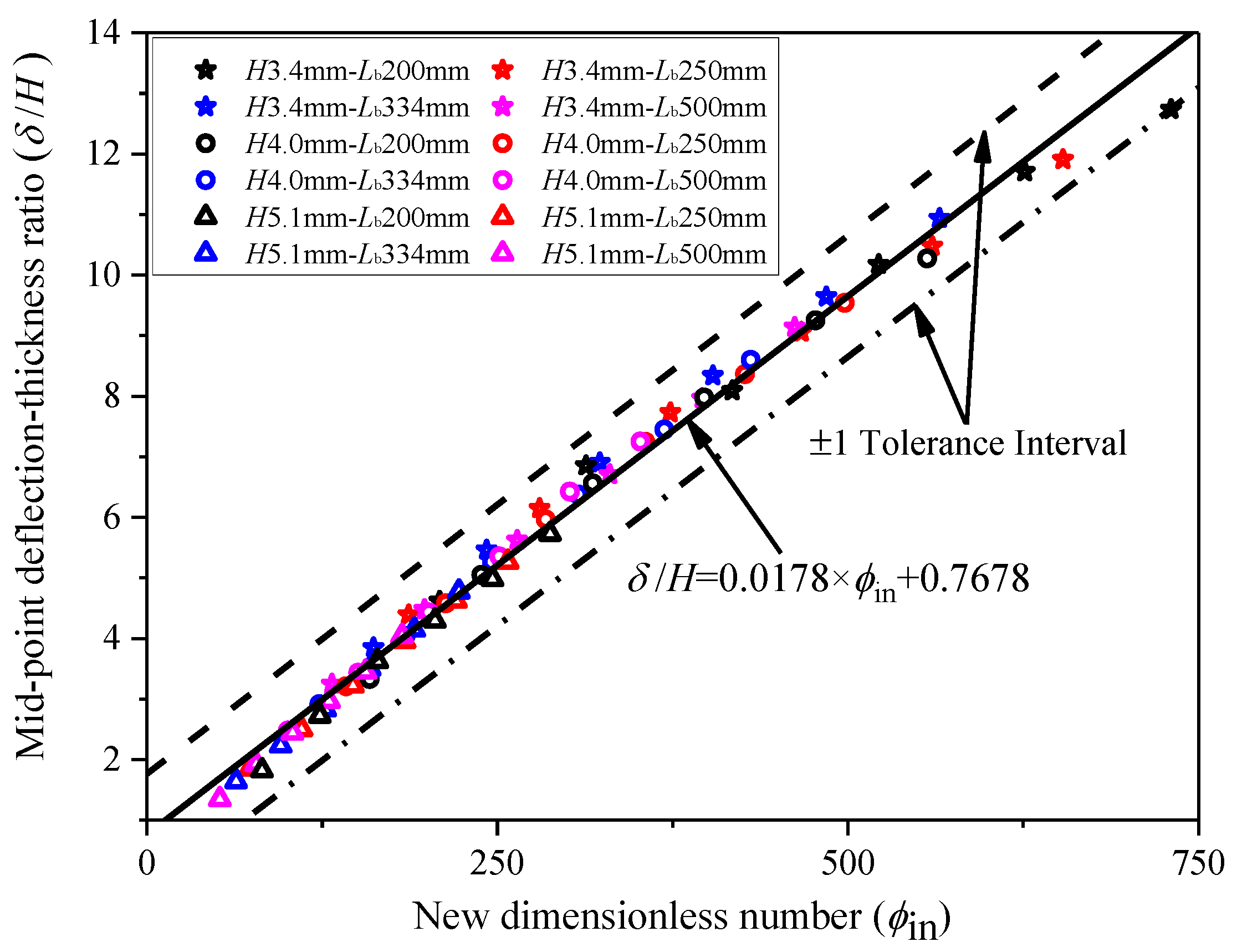
3.1. Application of the New Dimensionless Number for Confined Explosion in Cubic Chamber

A total of 28 tests of square plates subjected to confined blast loading were performed by Geretto et al. [6]. In their study, an explosive was detonated at the geometric center of a sealed cuboidal chamber, which confined the blast wave and all the explosive products within the chamber, as illustrated in Figure 1. The clamped box-shaped chamber consisted of six clamped rectangular plates with inner dimensions of 200 mm × 200 mm × 200 mm. Three different thicknesses of target plates (3 mm, 4 mm and 5 mm) were tested. The 3 mm and 4 mm plates were made from locally manufactured commercial-grade mild steel, and the 5 mm plate was made from grade 300WA steel. The quasistatic yield strengths of the different materials were obtained via uniaxial tensile tests. The yield strength of the 3 mm and 4 mm mild steel and the 5 mm 300WA steel were nominally found to be 233 MPa, 222 Mpa and 263 Mpa, respectively. The confined blast loading was generated by detonating different masses of spherically shaped plastic explosives (PE4) at the center of the chamber, which resulted in plate deflection ranging from one to fourteen times the plate thicknesses. The explosive (PE4) has a density of 1.601 g/cm3 and a detonation energy per unit volume of Ee = 9 × 10⁹ J/m3. These data were obtained by the authors of [32]. The plates subjected to confined blast loading experienced plastic deformation, which was characterized by a global uniform dome with a maximum deflection at the center of the plates. In the present study, the deformations of the top target plates were chosen as the research object. The calculated dimensionless number ϕ in and deflections δ / H for test plates subjected to fully confined blast loading are listed in Table 1.
The ratios of the midpoint deflections to the plate thicknesses ( δ / H ) versus the new dimensionless number ( ϕ in ) for different load conditions are presented in Figure 2. The experimental data in Geretto’s confined blast tests show an approximately linear relationship between the deflection–thickness ratio ( δ / H ) and the new dimensionless number ( ϕ in ). From the result of the least-squares correlation analysis, a relatively good correlation was shown between the measured midpoint deflection and the new dimensionless number, and the trend of the experimental data is expressed as follows,
δ H = 0.0178 ϕ in + 0.7678
The two dashed lines in Figure 2 are the results calculated by Equation (9) ± 1   δ / H respectively, which are drawn for the purpose of expressing the fitting accuracy. It is found that all the points of the experimental data are in the range of an experimental variation of one plate thickness.

3.2. Comparison with Nurick’s Dimensionless Number

In the studies of Nurick and Martin [27], by applying the dimensionless number ϕ q in the analysis of square plates under impulsive loads, it was found that the regression curve of the experimental data converged to a linear trend. Thus, the empirical expression was obtained with a correlation coefficient of 0.985, which was shown as follows,
δ H = 0.471 ϕ q + 0.001
The dimensionless number ϕ q = I 2 H 2 ( B L ρ σ 0 ) 1 / 2 , in which I is the impulse of the blast load, B, L and H are the breath, length and thickness of the plate, respectively, and ρ and σ 0 are the density and strength of the material.
However, it is inapplicable to predict the deflection of plates subjected to confined blast loading directly by Equation (10) due to the fact that the effective impulse applied on the plates in confined blast tests is difficult to be determined. In Geretto’s study [6], the deflections of plates under blast loading in three different degrees of confinement (free-air burst, fully vented and fully confined) were recorded. In the free-air blast tests, impulses applied on the plates were measured by the ballistic pendulum. The impulses for the free-air blast, together with the midpoint deflection ratios between the unconfined and confined test results, were employed to determine the effective impulse applied on the plates in the fully confined test. To account for variations in the target plate thickness, the midpoint deflections were normalized by Geretto et al. as follows [6],
δ n = δ × H H n
where δ n is the normalized deflection, H n is the nominal plate thickness, δ is the measured midpoint deflection and H is the measured plate thickness.
The normalized deflection–thickness ratio δ n / H n versus the dimensionless number ϕ q for the fully confined test is illustrated in Figure 3. It is shown that the data converge to a linear trend, which is consistent with the trend expressed in Equation (10). However, it is difficult to obtain the impulse of a confined blast load. The confined blast load consists of two distinctive phases. The first phase includes the initial shockwave from the explosive and multi-reflected shockwaves from the walls of the container. The second phase is known as quasistatic pressure, which lasts longer in the confined chamber. As a result, the confined blast load is more complex compared to the blast load from the explosive in the free-air condition. It is difficult to obtain the impulse used to calculate the deflection of the blast-loaded plate in a confined chamber. Therefore, the method suggested in Geretto’s study seems inconvenient to predict the deflection of plates subjected to confined blast loading in practice.
The empirical expression of Equation (9) was obtained with a correlation coefficient of 0.987 through the linear fit analysis. It can be applied to predict the deflection of plates subjected to confined blast loading with relatively good accuracy. Based on the results of comparative analysis, it is believed that the new dimensionless number ϕ in suggested in the present study, which considers the influence of the blast energy, the yield strength of the material, the plate thickness and the structural dimensions, can be used to better characterize the plate deflection under confined blast loading.

4. Analysis of the Deformation of Plates under Confined Explosion in Cuboid Chamber

4.1. Numerical Simulations

With the development of computer technology and computational mechanic techniques, numerical modeling has become a common tool to investigate plate response under blast loading. The commercial code ANSYS/AUTODYN has previously been used to analyze the dynamic response of steel plates under confined blast loading. The fully coupled Euler–Lagrange method has an advantage in dealing with the large deflection prediction of plates under confined blast loading. Here, the numerical modeling method was firstly validated based on the experimental results in Geretto’s study and then used to further analyze the large deflection of plates under a confined explosion in the cuboid chamber with different lengths. The following subsections provide details of the numerical modeling and results.

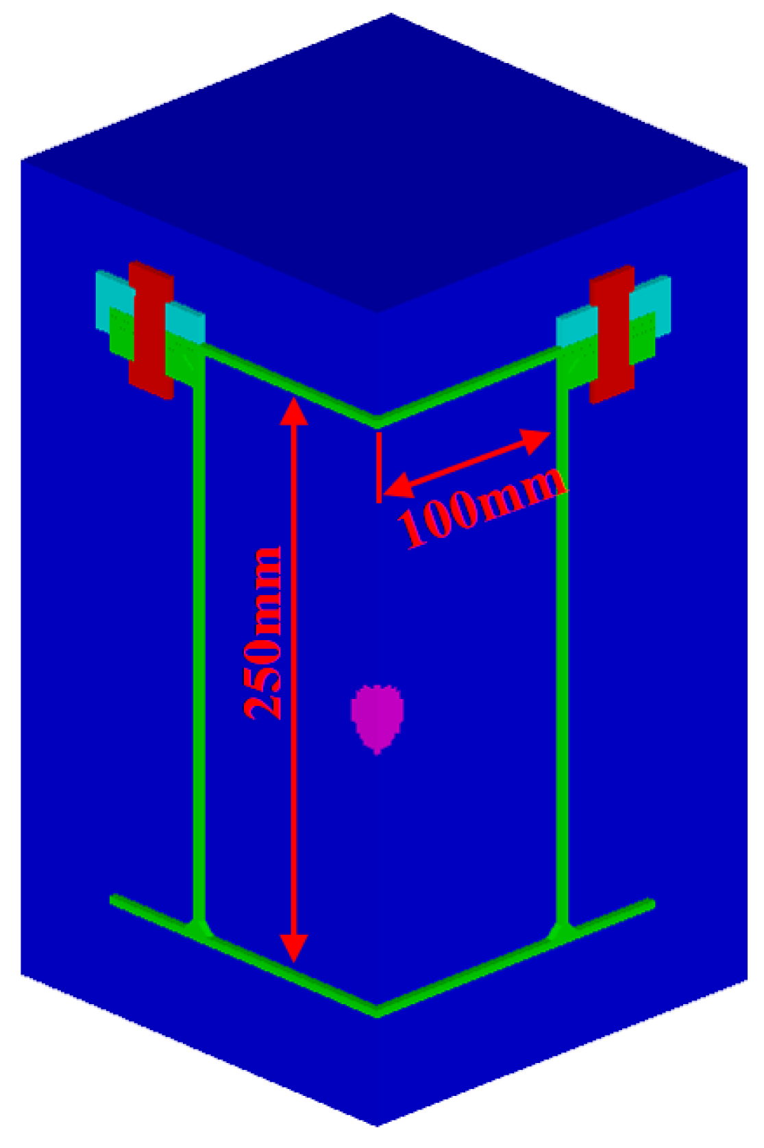
4.1.1. Numerical Modeling

In this section, numerical simulations of the confined blast tests in Geretto’s study were performed by using the nonlinear explicit code ANSYS/AUTODYN. The air was modeled using an Eulerian solver in the 3D simulation. The element sizes, characterized by the element length, corresponding to 1 mm, 2 mm and 4 mm were investigated. The final deformations and total CPU times for the three element lengths were then obtained. The results showed that the final midpoint deflection results of plates under confined blast loading were within 4% with the total CPU time for the element length of 1 mm four times than for the element length of 2 mm. Considering the balance between calculation accuracy and the time taken, an Eulerian element size of 2 mm × 2 mm × 2 mm was selected for the air domain with a geometric dimension of 400 mm × 400 mm × 400 mm in all numerical simulations. A spherical PE4 explosive charge was initialized in the center of the air domain and detonated. The flow-out boundary conditions were set on all free faces of the Euler grid. The PE4 material model available in the AUTODYN material library was employed. The Jones–Wilkins–Lee (JWL) Equation of State (EOS) was implemented to describe the explosive material, which is defined as follows,
p = C 1 ( 1 w r 1 v ) e r 1 v + C 2 ( 1 w r 2 v ) e r 2 v + w e v
In addition, the air is defined by an ideal gas equation of state, which can be expressed as follows,
p = ( γ 1 ) ρ e
where γ is the specific heat ratio, ρ is the density, e is the internal energy, C 1 , C 2 , r 1 , r 2 are constants, w is the specific heat and v is the specific volume. In the numerical model, the standard constants of air and PE4 are given as follows: air density ρ = 1.225   kg / m 3 , air initial internal energy e = 2.068 × 10 5   J / kg , ideal air gas constant γ = 1.4 . C 1 , C 2 , r 1 , r 2 and w are 6.0977 × 10 5   MPa , 1.295 × 10 4   MPa , 4.5, 1.4 and 0.25, respectively [33].
Figure 4 shows a quarter of the numerical model, which includes the fully confined container, the clamp restraints, the PE4 explosive charge and the air domain. In the numerical model, along the direction of length and width, a Lagrangian element size fixed at 2 mm × 2 mm was selected to discretize the box-shaped container except for the bolt hole area. The remaining part of the container was meshed with three-dimensional eight-noded solid elements, where the maximum element length in the direction of length and width was 2 mm. In the thickness direction, the plates of the container wall were divided into two grids. In order to provide an accurate representation of the experimental restraints, the clamp frame and bolts are included in the numerical model. The clamp frames and bolts were meshed with three-dimensional eight-noded solid elements and were modeled as rigid bodies. In order to simulate the attachment of the container to the heavy base, the bolts and the nodes around the bolt holes in the bottom plate were constrained from translation in all directions. The bolts and clamp frames offered a strong clamp on the top target plate in the experiments. The magnitude of the tensile stress provided by the bolt was 240 Mpa [32], which was determined through several experiments where an instrumented bolt was tightened, and the stress levels in the bolts were recorded. During the simulation, the lower clamp frame was fixed and constant pressure was applied on the bolts to represent the clamp restraints. The contact between the two surfaces (e.g., the top target plate and clamp frames and the clamp frames and bolt heads) was controlled by employing a surface-to-surface penalty-based contact algorithm. The contact condition between nodes and the surface (e.g., the bolts and the edge of the bolt holes in the target plate) were controlled by using the node-to-surface contact penalty-based algorithm. A static friction coefficient of 0.2 was assigned to define the friction force between the two surfaces in the simulation.
In the finite element modeling, the Johnson–Cook constitutive relation was used to predict the numerical plastic response of the target plates under confined blast loading, which is given as follows [33],
σ y = ( A + B ε n ) ( 1 + C ln ε ˙ ) ( 1 T m )
where A , B , C , n and m are material parameters, ε is the effective plastic strain, ε ˙ = ε ˙ / ε ˙ 0 denotes the effective plastic strain rate, ε ˙ 0 is the reference strain rate and was set to be 4.17 × 10 4 s 1 . T m = ( T T r ) / ( T m T r ) , T is the material temperature, T r is room temperature and T m is the melting temperature of the material. The Johnson–Cook material parameters for the container materials with different thicknesses were in accordance with Geretto’s study [32].
In the numerical simulation, the coupling between Euler and the Lagrangian meshes are performed by defining the “fully automatic” Euler–Lagrange coupling option available in AUTODYN. The data pick-up points are positioned at the center of the top target plate to record the midpoint deflection.

4.1.2. Numerical Result

From the results of the simulations, the top target plates all experienced a similar deformation mode. Figure 5 shows the typical deformation behavior of the target top plate (Case FC-3-6) subjected to confined blast loading. Plastic hinges are formed along the clamped boundary and 45° from the corners to the center of the plate; therefore, the deflections of the central plate keep the same value. After the plastic hinges meet at the center of the plate, the maximum deflection occurs in the midpoint of the plate. It is found that the final deformation mode of the top target plates was consistent with the experimental observation, which was characterized by a uniform global dome with the maximum deflection at the center of the plate. The midpoint deflection was selected as the research object in the deformation analysis of plates under confined blast loading here. During the dynamic response, the explosive energy was firstly transformed into the internal energy of the air and the kinetic energy and deformation energy of the blast-loaded structures. The kinetic energy was then also transformed into the deformation energy of the structures after the deformation stability. The energy of the whole system was balanced during the dynamic response in the confined blast cases. Figure 6 shows the typical midpoint deflection–time history of the target top plate (Case FC-3-6) subjected to confined blast loading. The blast wave and pressure in the confined chamber cause bulging of the top target plate up to the maximum transient value, followed by dampened elastic oscillations leading to the final deflection. It is found that the amplitude of the elastic oscillations was to a very small extent. Under the confined blast loading, the plastic deformation predominated the dynamic response of the plates. The present empirical modeling focuses on the final midpoint deflection prediction. The numerical modeling would be used to provide more deformation data with similar conditions for the deduction and validation of the empirical model. Therefore, the numerical modeling method was validated through the comparison of experimental and numerical results on midpoint deflections. The final midpoint deflection–thickness ratio obtained from the simulations are plotted against the experimental results in Figure 7. The dashed lines represent the confidence interval ( ± 1 plate thickness) of the top target plates tested. The numerical results were all bounded on either side of the experimental data by a one-deflection–thickness ratio confidence limit. In general, the results show a good correlation between the numerical and experimental results for all the top target plates.

4.2. Application of the New Dimensionless Number for Confined Explosion in the Cuboid Chamber

In the present study, the validated numerical method was employed to further investigate the dynamic response of square plates under a confined explosion in a cuboid chamber. A series of numerical simulations with different container lengths of 250 mm, 334 mm and 500 mm (the other two dimensions remain the same with the cubic container) were performed to analyze the deflection of the top target plates subjected to a confined blast load. The width and height of the container have a constant value of 200 mm in the simulations. Spherical PE4 explosives with different masses ranging from 20 g to 70 g were detonated in the center of the container to provide the confined blast load. The boundary constraints of the fully confined chamber were identical to the numerical models used in the numerical simulations of Geretto’s experiments. Three different thicknesses of 3 mm, 4 mm and 5 mm target plates were modeled. Figure 8 shows the numerical model in the simulation with the chamber length of 250 mm. In total, 54 different load conditions were assigned in the numerical simulations, as listed in Table 2.
In the simulations, the deformation profiles of the top target plates were all characterized by a large permanent central deflection several times more than the plate thickness and a uniform global dome. The permanent midpoint deflection of the top target plate in each simulation was chosen as the object, and the numerical results are listed in Table 3. The dimensionless number ϕ in as expressed in Equation (7) was then used to calculate the deflections of square plates under different confined explosions in the cuboid chamber. Table 3 shows the detailed values of the dimensionless number ϕ in and the midpoint deflection–thickness ratio δ / H of the top target plates in all simulations. In addition, the relationship between the results of midpoint deflection–thickness ratio δ / H and the values of the dimensionless number ϕ in were plotted in the coordinate of ( ϕ in ,   δ / H ) , as shown in Figure 9, which shows a clear linear relationship between the midpoint deflection–thickness ratio and the new dimensionless number. The solid line in Figure 9 is a linear-fitting expression of the results calculated by Equation (9), and the two dashed lines are the results from Equation (9) ±   1   δ / H , which are drawn for the purpose of reflecting the fitting accuracy. It is found that the deflection results were all bounded on either side of the linear-fitted values by a one-deflection–thickness ratio confidence limit.

5. Discussions

In this section, based on the validated numerical method, a series of numerical models with target plate thicknesses of 2 mm and 6 mm were performed for confined explosions in a cuboid chamber with lengths of 200 mm, 225 mm, 334 mm and 500 mm. The length of the fully confined chamber, the plate thickness, the charge mass and the material strength in the simulations are listed in Table 4. The numerical results were compared with the values calculated by Equation (9) to verify the validity of the proposed empirical expression in predicting the deflection of the plates under a fully confined explosion.
The predicted final midpoint deflections based on the empirical expression of Equation (9) and the corresponding numerical results are also summarized in Table 4. The predicted midpoint deflection–thickness ratios are plotted against the numerical midpoint deflection–thickness ratios for all the 2 mm and 6 mm plates in Figure 10. It is shown that the predicted results were all bound on either side of the numerical data by a one-deflection–thickness ratio confidence limit. The predicted midpoint deflections agree well with the corresponding numerical results, indicating that the empirical expression of Equation (9), based on the new dimensionless number ϕ in , is capable of calculating the deflection of the square plates under confined explosions in a cuboid chamber with different lengths. The deflection prediction method based on the new dimensionless number ϕ in is very convenient for engineering applications. The specific steps to obtain the plate deflection are as follows: (1) the dimensionless number ϕ in is determined firstly based on these parameters, including the explosive volume, the strength of the material, the plate thickness, the length of the confined chamber and the length of the square plate; (2) the deflection–thickness ratio is then determined based on the empirical expression of Equation (9) and the new dimensionless number; (3) the deflection of the plate under confined blast loading is finally determined based on the deflection–thickness ratio and the plate thickness.
However, the empirical expression used to calculate the midpoint deflection does not incorporate failure. For the plates under uniform blast loading, the region enclosed by a midpoint deflection–thickness ratio of 12.5 represents Mode I failure (large inelastic deformation), as observed by Nurick and Martin [27]. Therefore, the proposed empirical expression of Equation (9), based on the new dimensionless number ϕ in , is only applicable for the deflection prediction of confined blast cases in which the explosive is at the center of the chamber and the midpoint deflection–thickness ratios of the plates are under 12.5.
In order to further validate the efficiency and accuracy of the present work, a comparison was conducted between the deflection prediction method based on the new dimensionless number and another method. Yao [34] proposed a dimensionless number D in for the dynamic response analysis of square plates subjected to fully confined blast loading in a cubic chamber, which was expressed as follows,
D in = Q σ 0 L 2 H
The empirical expression used to predict the deflection–thickness ratio of the plates under confined blast loading were expressed as follows,
δ H = 0.79 D in
As Yao’s method is only applicable to a confined explosion in a cubic chamber, the midpoint deflections of the plates with thicknesses of 2 mm and 6 mm subjected to a confined explosion in the cubic chamber were selected as the research objects. A comparison of the predicted midpoint deflections of the 2 mm and 6 mm target plates by different methods is illustrated in Table 5.
It is shown that the predicted results of the 2 mm target plates by the empirical expression in Yao’s study are significantly less than the numerical results, whereas the predicted midpoint deflections in the present study agree well with the corresponding numerical results. From the above, the deflection prediction method based on the new dimensionless number ϕ in not only has a wider application for usage in a confined explosion in a cuboid chamber with different lengths but is also capable of predicting plate deflections more efficiently and accurately, which is of practical value in engineering applications.

6. Conclusions

Based on a general dimensional analysis, a new dimensionless number ϕ in , which considers the influence of the blast energy, the strength of the material, the plate thickness, the length of the confined chamber and other structural dimensions, was proposed for characterizing the deflection of square plates subjected to fully confined blast loading. A comparison analysis is made between the applications of the dimensionless number ϕ q proposed by previous scholars and the new dimensionless number ϕ in . It is found that the new dimensionless number ϕ in is more efficient and accurate for the dynamic response analysis of blast-loaded plates in a confined chamber. The explosive is at the center of the chamber and the midpoint deflection–thickness ratio of the plates is under 12.5. It has a further wide field of application with respect to structural response analysis in a confined blast situation, especially when the plate experiences a large deflection–thickness ratio.
The new dimensionless number ϕ in was further employed to analyze the experimental and numerical data of deflections of the plate subjected to confined blast loading in chambers with different lengths. The comparison results revealed that the empirical expression based on the new dimensionless number ϕ in is capable of efficiently and accurately predicting the response of square plates subjected to confined explosions in a chamber with different lengths, which would be helpful in the design of blast-loaded structures.

Author Contributions

Conceptualization and writing—original manuscript, C.Z., Y.W., X.K., H.Z., H.L., and W.W. All authors have read and agreed to the published version of the manuscript.

Funding

This work is performed with the support of the National Defense Basic Scientific Research Program (JCKY2017110C001), the Fundamental Research Funds for the Central Universities (WUT: 2019IVA010, 2020III036), and the Open Fund of Key Laboratory of High Performance Ship Technology (Wuhan University of Technology), Ministry of Education (No. gxnc19051805).

Conflicts of Interest

The authors declare no conflict of interest.

References

  1. Kong, X.S.; Wu, W.G.; Li, J.; Chen, P.; Liu, F. Experimental and numerical investigation on a multi-layer protective structure under the synergistic effect of blast and fragment loadings. Int. J. Impact Eng. 2014, 65, 146–162. [Google Scholar] [CrossRef]
  2. Pickerd, V.; Bornstein, H.; Mccarthy, P.; Buckland, M. Analysis of the structural response and failure of containers subjected to internal blast loading. Int. J. Impact Eng. 2016, 95, 40–53. [Google Scholar] [CrossRef]
  3. Edri, I.; Savir, Z.; Feldgun, V.R.; Karinski, Y.S.; Yankelevsky, D.Z. On blast pressure analysis due to a partially confined explosion: I. experimental studies. Int. J. Prot. Struct. 2011, 2, 1–20. [Google Scholar] [CrossRef]
  4. Dragos, J.; Wu, C.; Oehlers, D.J. Simplification of fully confined blasts for structural response analysis. Eng. Struct. 2013, 56, 312–326. [Google Scholar] [CrossRef]
  5. Wu, C.; Lukaszewicz, M.; Schebella, K.; Antanovskii, L. Experimental and numerical investigation of confined explosion in a blast chamber. J. Loss Prev. Process Ind. 2013, 26, 737–750. [Google Scholar] [CrossRef]
  6. Geretto, C.; Chung Kim Yuen, S.; Nurick, G.N. An experimental study of the effects of degrees of confinement on the response of square mild steel plates subjected to blast loading. Int. J. Impact Eng. 2015, 79, 32–44. [Google Scholar] [CrossRef]
  7. Duffey, T.A.; Romero, C. Strain growth in spherical explosive chambers subjected to internal blast loading. Int. J. Impact Eng. 2003, 28, 967–983. [Google Scholar] [CrossRef]
  8. Karpp, R.R.; Duggry, T.A.; Neal, T.R. Response of containment vessels to explosive blast loading. J. Press. Vessel Technol. 1983, 105, 23–27. [Google Scholar] [CrossRef]
  9. Dong, Q.; Li, Q.M.; Zheng, J.Y. Interactive mechanisms between the internal blast loading and the dynamic elastic response of spherical containment vessels. Int. J. Impact Eng. 2010, 37, 349–358. [Google Scholar] [CrossRef] [Green Version]
  10. Burman, N.M.; Saunders, D.S.; Ritzel, D.V.; Buckland, M.E. Deformation and Fracture of Compartments Subjected to Internal Blast Loading. In 5th Australian Aeronautical Conference: Preprints of Papers; Institution of Engineers: Barton, Australia, 1993; pp. 533–540. [Google Scholar]
  11. Turner, T. Deformation and Failure in Compartments Subjected to Internal Blast Loading: Part 1 Experimental Series; DSTO technical report, DSTO-TR-1038; Defence Science & Technology Organisation (DSTO) Press: Melbourne, Australia, 2000.
  12. Rushton, N.; Schleyer, G.K.; Clayton, A.M.; Thompson, S. Internal explosive loading of steel pipes. Thin-Walled Struct. 2008, 46, 870–877. [Google Scholar] [CrossRef]
  13. Clubley, S.K. Non-linear long duration blast loading of cylindrical shell structures. Eng. Struct. 2014, 59, 113–126. [Google Scholar] [CrossRef] [Green Version]
  14. Ma, L.; Hu, Y.; Zheng, J.Y.; Deng, G.D.; Chen, Y.J. Failure analysis for cylindrical explosion containment vessels. Eng. Fail. Anal. 2010, 17, 1221–1229. [Google Scholar] [CrossRef]
  15. Zillacus, S.; Phyillaier, W.E.; Shorrow, P.K. The Response of Clamped Circular Plates to Confined Explosive Loadings; DTIC Document; Naval Ship Research and Development Center: Bethesda, MD, USA, 1974.
  16. Zheng, C.; Kong, X.S.; Wu, W.G.; Liu, F. The elastic-plastic dynamic response of stiffened plates under confined blast load. Int. J. Impact Eng. 2016, 95, 141–153. [Google Scholar] [CrossRef]
  17. Zheng, C.; Kong, X.S.; Wu, W.G.; Xu, S.X.; Guan, Z.W. Experimental and numerical studies on the dynamic response of steel plates subjected to confined blast loading. Int. J. Impact Eng. 2018, 113, 144–160. [Google Scholar] [CrossRef]
  18. Zhao, N.; Yao, S.; Zhang, D.; Lu, F.; Sun, C. Experimental and numerical studies on the dynamic response of stiffened plates under confined blast loads. Thin-Walled Struct. 2020, 154, 106839. [Google Scholar] [CrossRef]
  19. Rabczuk, T.; Areias, P.M.A.; Belytschko, T. A meshfree thin shell method for non-linear dynamic fracture. Int. J. Numer. Methods Eng. 2007, 72, 524–548. [Google Scholar] [CrossRef] [Green Version]
  20. Rabczuk, T.; Belytschko, T. A three-dimensional large deformation meshfree method for arbitrary evolving cracks. Comput. Methods Appl. Mech. Eng. 2007, 196, 2777–2799. [Google Scholar] [CrossRef] [Green Version]
  21. Rabczuk, T.; Gracie, R.; Song, J.H.; Belytschko, T. Immersed particle method for fluid–structure interaction. Int. J. Numer. Methods Eng. 2010, 81, 48–71. [Google Scholar] [CrossRef]
  22. Lin, C.C.; Segel, L.A. Mathematics Applied to Deterministic Problems in the Natural Sciences; Macmillan Publishing Co., Inc.: New York, NY, USA, 1974. [Google Scholar]
  23. Bridgman, P. Dimensional Analysis; Yale University Press: New Haven, CT, USA, 1922. [Google Scholar]
  24. Johnson, W. Impact Strength of Materials; Edward Arnold: London, UK, 1972. [Google Scholar]
  25. Jones, N. Structural Impact; Cambridge University Press: Cambridge, UK, 1989. [Google Scholar]
  26. Li, Q.M.; Jones, N. On dimensionless numbers for dynamic plastic response of structural members. Arch. Appl. Mech. 2000, 70, 245–254. [Google Scholar] [CrossRef]
  27. Nurick, G.N.; Martin, J.B. Deformation of thin plates subjected to impulsive loading—A review: Part II: Experimental studies. Int. J. Impact Eng. 1989, 8, 171–186. [Google Scholar] [CrossRef]
  28. Zhao, Y.P. Suggestion of a new dimensionless number for dynamic plastic response of beams and plates. Arch. Appl. Mech. 1998, 68, 524–538. [Google Scholar] [CrossRef]
  29. Jacob, N.; Nurick, G.N.; Langdon, G.S. The effect of stand-off distance on the failure of fully clamped circular mild steel plates subjected to blast loads. Eng. Struct. 2007, 29, 2723–2736. [Google Scholar] [CrossRef]
  30. Mostofi, T.M.; Babaei, H.; Alitavoli, M.; Hosseinzadeh, S. On dimensionless numbers for predicting large ductile transverse deformation of monolithic and multi-layered metallic square targets struck normally by rigid spherical projectile. Thin-Walled Struct. 2017, 112, 118–124. [Google Scholar] [CrossRef]
  31. Feldgun, V.; Karinski, Y.; Edri, I.; Yankelevsky, D.Z. Prediction of the quasi-static pressure in confined and partially confined explosions and its application to blast response simulation of flexible structures. Int. J. Impact Eng. 2016, 90, 46–60. [Google Scholar] [CrossRef]
  32. Geretto, C. The Effects of Different Degrees of Confinement on the Deformation of Square Plates Subjected to Blast Loading. Ph.D. Dissertation, University of Cape Town, Cape Town, South Africa, 2012. [Google Scholar]
  33. ANSYS AUTODYN 14.0. Theory Manual; ANSYS, Inc.: Pittsburgh, PA, USA, 2005; pp. 147–148.
  34. Yao, S.J.; Zhang, D.; Lu, F.Y. Dimensionless number for dynamic response analysis of box-shaped structures under internal blast loading. Int. J. Impact Eng. 2016, 98, 13–18. [Google Scholar] [CrossRef]
Figure 1. Illustration of the test device of the fully confined blast.
Jmse 08 01031 g001
Figure 2. The measured deflection–thickness ratio versus the new dimensionless number ( ϕ in ) for the confined blast tests.
Jmse 08 01031 g002
Figure 3. The normalized deflection–nominal thickness ratio ( δ n / H n ) versus the dimensionless number ( ϕ q ) for Geretto’s confined blast tests.
Jmse 08 01031 g003
Figure 4. Quarter of the three-dimensional numerical model.
Jmse 08 01031 g004
Figure 5. Deformation contour plot of the test plate (Case FC-3–6) at different times. (a) T = 0.18 ms; (b) T = 0.30 ms; (c) T = 0.50 ms.
Jmse 08 01031 g005
Figure 6. Typical midpoint deflection–time history of the target top plate (Case FC-3-6).
Jmse 08 01031 g006
Figure 7. Numerical versus experimental results on the midpoint deflection–thickness ratio.
Jmse 08 01031 g007
Figure 8. Numerical versus experimental results on the midpoint deflection–thickness ratio.
Jmse 08 01031 g008
Figure 9. The midpoint deflection–thickness ratio versus the new dimensionless number ϕ in .
Jmse 08 01031 g009
Figure 10. The predicted results versus the numerical results of the midpoint deflection–thickness ratios of the 2 mm and 6 mm target plates.
Jmse 08 01031 g010
Table 1. Dimensionless number and deflection for the test plates in Geretto’s confined blast tests.
Test Number Plate Thickness H (mm) Yield Strength σ 0 (Mpa) Mass of Explosive M c (g) Top Plate Deflection δ (mm) δ H ϕ in
FC-3-13.42332016.34.79208.7
FC-3-23.42332015.74.62208.7
FC-3-33.42333023.36.85313.1
FC-3-43.52333021.86.23295.4
FC-3-53.42334027.58.09417.4
FC-3-63.32335034.610.48553.9
FC-3-73.42336039.811.71626.1
FC-3-83.42332016.34.79208.7
FC-4-14.02222011.62.90158.3
FC-4-24.12223019.24.68226.0
FC-4-34.02224024.46.10316.5
FC-4-44.12224025.66.24301.3
FC-4-54.12223019.74.80226.0
FC-4-64.12222013.03.17150.6
FC-4-74.02225031.97.98395.7
FC-4-84.12225031.07.56376.6
FC-4-94.02226037.09.25474.8
FC-5-15.1263208.91.7582.2
FC-5-25.1263209.31.8282.2
FC-5-35.12633013.92.73123.3
FC-5-45.12633013.72.69123.3
FC-5-55.12634017.83.49164.4
FC-5-65.12634018.53.63164.4
FC-5-75.12635021.94.29205.4
FC-5-85.12635021.14.14205.4
FC-5-95.12636025.44.98246.5
FC-5-105.12637029.25.73287.6
Table 2. Dimensions of the containers and loading conditions in the simulations.
Model Ref.Length (mm)Thickness (mm)Yield Strength (MPa)Charge Mass (g)Model Ref.Length (mm)Thickness (mm)Yield Strength (MPa)Charge Mass (g)
GK250-3-12503.423320GK334-4-43344.022250
GK250-3-22503.423330GK334-4-53344.022260
GK250-3-32503.423340GK334-4-63344.022270
GK250-3-42503.423350GK500-4-15004.022220
GK250-3-52503.423360GK500-4-25004.022230
GK250-3-62503.423370GK500-4-35004.022240
GK334-3-13343.423320GK500-4-45004.022250
GK334-3-23343.423330GK500-4-55004.022260
GK334-3-33343.423340GK500-4-65004.022270
GK334-3-43343.423350GK250-5-12505.126320
GK334-3-53343.423360GK250-5-22505.126330
GK334-3-63343.423370GK250-5-32505.126340
GK500-3-15003.423320GK250-5-42505.126350
GK500-3-25003.423330GK250-5-52505.126360
GK500-3-35003.423340GK250-5-62505.126370
GK500-3-45003.423350GK334-5-13345.126320
GK500-3-55003.423360GK334-5-23345.126330
GK500-3-65003.423370GK334-5-33345.126340
GK250-4-12504.022220GK334-5-43345.126350
GK250-4-22504.022230GK334-5-53345.126360
GK250-4-32504.022240GK334-5-63345.126370
GK250-4-42504.022250GK500-5-15005.126320
GK250-4-52504.022260GK500-5-25005.126330
GK250-4-62504.022270GK500-5-35005.126340
GK334-4-13344.022220GK500-5-45005.126350
GK334-4-23344.022230GK500-5-55005.126360
GK334-4-33344.022240GK500-5-65005.126370
Table 3. Deflections of plates under confined explosion in the cuboid chamber with different lengths.
Model Ref. ϕ in Midpoint Deflection (mm)Midpoint Deflection–Thickness RatioModel Ref. ϕ in Midpoint Deflection (mm)Midpoint Deflection–Thickness Ratio
GK250-3-1186.714.94.4GK334-4-4307.625.56.4
GK250-3-2280.020.96.1GK334-4-5369.129.87.4
GK250-3-3373.326.37.7GK334-4-6430.634.48.6
GK250-3-4466.730.89.1GK500-4-1100.59.92.5
GK250-3-5560.035.610.5GK500-4-2150.813.73.4
GK250-3-6653.440.511.9GK500-4-3201.117.74.4
GK334-3-1161.513.13.8GK500-4-4251.421.45.4
GK334-3-2242.318.65.5GK500-4-5301.625.76.4
GK334-3-3323.023.56.9GK500-4-6351.929.07.3
GK334-3-4403.828.48.3GK250-5-173.59.41.8
GK334-3-5484.532.89.6GK250-5-2110.312.82.5
GK334-3-6565.337.210.9GK250-5-3147.016.43.2
GK500-3-1132.011.03.2GK250-5-4183.820.24.0
GK500-3-2198.015.24.5GK250-5-5220.523.64.6
GK500-3-3264.019.15.6GK250-5-6257.326.95.3
GK500-3-4330.022.86.7GK334-5-163.68.41.6
GK500-3-5396.027.18.0GK334-5-295.411.42.2
GK500-3-6462.031.19.1GK334-5-3127.214.42.8
GK250-4-1142.212.83.2GK334-5-4159.017.93.5
GK250-4-2213.318.34.6GK334-5-5190.821.14.1
GK250-4-3284.423.96.0GK334-5-6222.624.44.8
GK250-4-4355.529.07.2GK500-5-152.06.91.3
GK250-4-5426.633.58.4GK500-5-278.09.81.9
GK250-4-6497.738.29.5GK500-5-3103.912.52.4
GK334-4-1123.011.72.9GK500-5-4129.915.13.0
GK334-4-2184.516.24.0GK500-5-5155.917.63.5
GK334-4-3246.021.05.3GK500-5-6181.920.64.0
Table 4. Predicted and numerical results for the midpoint deflections of the 2 mm and 6 mm target plates.
Serial NumberThickness/mmChamber Length/mmCharge/gMidpoint Deflection/mmMidpoint Deflection/Thickness Ratio
FEMEmpirical FormulaFEMEmpirical Formula
122001012.912.36.56.1
222002022.123.011.111.5
322501011.311.15.75.6
422502021.520.710.810.4
523341010.29.85.14.9
623342019.018.29.59.1
72500107.78.33.94.2
825002015.615.17.87.6
96200208.210.91.41.8
1062003011.914.12.02.4
1162004015.117.32.52.9
1262005018.320.53.13.4
1362006021.523.63.63.9
1462007024.626.84.14.5
156250206.910.31.21.7
1662503010.613.11.82.2
1762504013.515.92.22.7
1862505016.318.82.73.1
1962506019.321.63.23.6
2062507022.324.43.74.1
216334205.59.50.91.6
226334308.812.01.52.0
2363344011.614.41.92.4
2463345014.016.92.32.8
2563346016.719.32.83.2
2663347019.521.83.23.6
276500204.08.60.71.4
286500306.810.61.11.8
296500409.712.61.62.1
3065005012.014.62.02.4
3165006013.916.62.32.8
3265007016.518.62.83.1
Table 5. Comparison of the predicted midpoint deflections of the 2 mm and 6 mm target plates.
Serial
Number
Thickness/mmChamber Length
/mm
Charge
/g
Midpoint Deflection/Thickness RatioMidpoint Deflection/Thickness Ratio
FEMEmpirical Expression in Yao’s StudyFEMEmpirical Expression in Present Study
12200106.52.46.56.1
222002011.14.811.111.5
36200201.41.41.41.8
46200302.02.12.02.4
56200402.52.82.52.9
66200503.13.53.13.4
76200603.64.23.63.9
86200704.14.94.14.5
Publisher’s Note: MDPI stays neutral with regard to jurisdictional claims in published maps and institutional affiliations.

