1. Introduction
The importance of forced long waves, or bound waves, to the oceans dynamics is well established in the literature, especially in shallow waters. However, in nature, some processes related to their generation, propagation, shoaling and dissipation are yet not fully understood, with eventual conflicting concepts to explain the same processes. A plausible partial explanation is that those concepts emerge from different interpretations of the bound wave theory first introduced by Longuet-Higgins and Stewart [
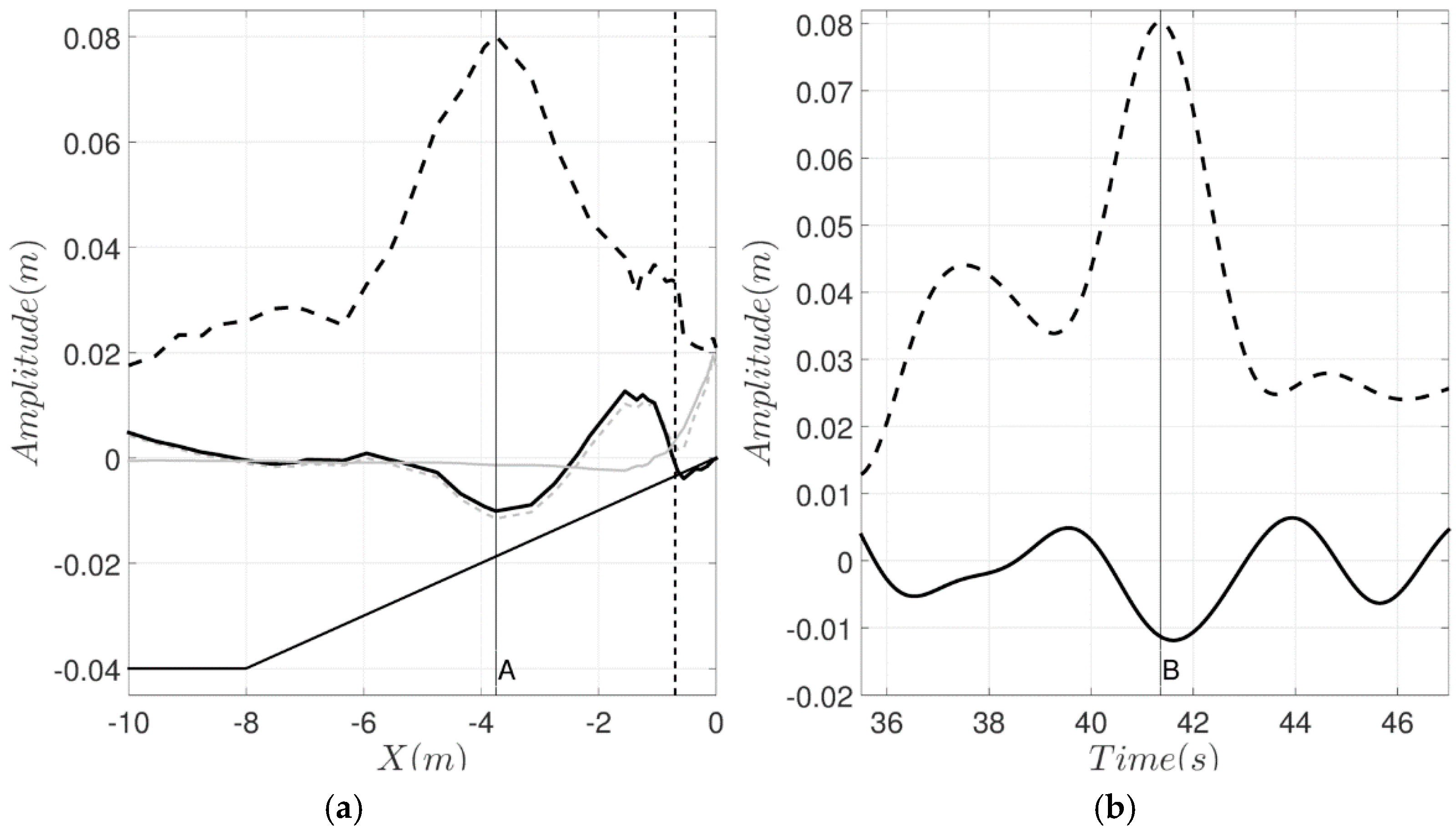
1]. For steady groups, two solutions have been proposed for forced waves by wave groups, which differ in the definition of the water level about which the forced waves oscillate. These indicate a forced wave oscillating either around or solely below the mean water level for the short waves, respectively (
Figure 1). The difference between the two interpretations is the constant of integration, which can be taken as the still water level or mean water level under the group, which for a steady condition may be arbitrarily chosen giving the long wave response as [
1]
and which has been widely adopted to estimate the forced wave amplitude from the magnitude of the radiation stress
derived from the short wave amplitude or wave envelope. Here,
is the constant water density,
is the group velocity,
g is the acceleration due to gravity and
h is the local water depth.
This solution emerges from the mass and momentum balance equations including the radiation stress forcing function as
where
and
are the long wave surface displacement and horizontal velocity, respectively. The solution domain is from the bed to the free surface, and initial conditions are discussed further below.
Equation (1) is the forced part of solution to the non-homogenous differential equations, which allows free waves (the homogenous solution) to be added to the forced wave term [
3]. The additional free waves may become important in a transient solution, but these have most often been ignored in analysis and modelling of bound wave propagation by treating this as a quasi-steady process. Transient solutions to similar problems dates back to Proudman [
4], who proposed dynamical theories of water motions induced by a moving pressure field. Whitham [
5] first addressed this issue with respect to the bound wave problem. Later, Molin [
6] and Mei and Benmoussa [
7] extended the investigation to sloping bottoms. The difference in interpretation of the forced wave as illustrated in
Figure 1 is important during shoaling. With a bound wave with both positive and negative components then shoaling (an increase in amplitude in shallower water) does not necessarily require radiation of free waves to ensure continuity of volume, but with a bound wave of pure depression, then an increase in amplitude of that depression requires radiation of free waves to ensure continuity. Radiation of those free waves then changes the shape of the total infragravity wave during shoaling, and may also influence the commonly observed lag between incident bound waves and the incoming short wave envelope.
Nielsen and Baldock [
8] presented simple analytical transient solutions to the response of the surface elevation to both non-resonant (finite water depth conditions) and resonant (shallow water conditions) radiation stress forcing. This solution has the same initial conditions as those proposed for startup of a submarine landslide that may trigger tsunami [
9,
10], i.e., a flat water surface and no flow velocity. In summary, for a 1-D scenario and assuming an abrupt onset of a non-resonant positive forcing with a Gaussian shape, three waves are generated: a purely negative forced wave, propagating phase locked with the forcing, and two free waves with positive amplitude and opposite direction of propagation. While the shape of all three waves are the same as the forcing, the free wave amplitudes depend on the ratio between the wave group velocity and the shallow water wave celerity as
where
and
are the amplitudes of the forced and the two free waves respectively.
At the resonant condition (short waves in shallow water), the free long waves arising from the initial condition cannot radiate away, forming a N-shaped wave, with a positive hump leading the forced wave. The total long wave surface grows linearly in time, but with the shape of the derivative of the forcing, rather than the inverse shape as in the steady solution. Changes in the shape of the bound wave from a symmetrical depression to an asymmetrical depression plus surge leading wave has been reported to occur during the shoaling processes, where again purely forced [
11] and a mix of forced and free waves [
8] interpretations have been provided.
During short wave breaking, the assumption that bound waves are released as free waves is commonly adopted [
12,
13,
14]. However, strong infragravity wave dissipation has also been observed, suggesting that bound waves are not released during the breaking process, but remain phase locked (forced) in the surf zone decaying with the short wave forcing [
15,
16,
17]. Breaking of shorter infragravity waves close to the shoreline [
18], friction [
19] and energy transfer [
20] and dissipation due to the existence of turbulence in the surf zone [
13] have been proposed or suggested as additional or alternate reasons for dissipation of forced wave energy.
Even though the generation of free waves due to the unsteady nature of forced bound waves have been discussed in different studies [
7,
8,
21], it is not clearly addressed in others, where the interpretation of the results relies on the quasi-steady solution [
11,
12,
13,
22]. To date, generation and radiation of free waves during bound wave shoaling has not been documented in observations, but the shape of the long wave and its phase (lag) relative to the forcing is observed to change. In part this may be due to errors in wave generation, the predominance of shallow water conditions, and the likely small magnitude of the free waves. Nevertheless, it is important to comprehend the possible effects of such free wave generation in the interpretation of propagating and shoaling infragravity waves. The analysis is based on numerical results and previous published laboratory data.
The paper is organised as follows: In
Section 2, aspects related to the shape change of the bound wave during shoaling, the possible consequences of the generation of free waves on the observed shoaling rate and lag of the long wave are discussed. A simple semi-analytical model is constructed to evaluate the model concepts of Nagase and Mizuguchi [
21] and Nielsen and Baldock [
8] and to quantify how the group frequency influences the apparent shoaling rate and lag of the long waves. In
Section 3, the possibility of dissipation of long waves by surf zone turbulence is investigated using the COULWAVE Boussinesq wave model, and particularly if the frequency dependence suggested by Battjes [
13] occurs in the model results. Final remarks are presented in
Section 4.
2. Bound Wave Shoaling
During bound wave shoaling two processes have often been observed: changes in shape, with the development of a leading positive surge and a lag of the long wave in time relative to the short wave envelope; and a shoaling rate dependence on the slope and frequency of the bound wave [
12,
13,
18,
23,
24]. From the static quasi equilibrium approach, the positive surge ahead of the short wave group can be interpreted as the stronger response of surface elevation to the radiation stress gradients in shallow water and an asymmetry in the short wave envelope as the wave group shoals. The main argument presented by Baldock [
11] when analysing single transient wave groups was the very close match of the spatial gradients of the wave envelope (radiation stress) with the spatial gradients of the long, as in Longuet-Higgins and Stewart [
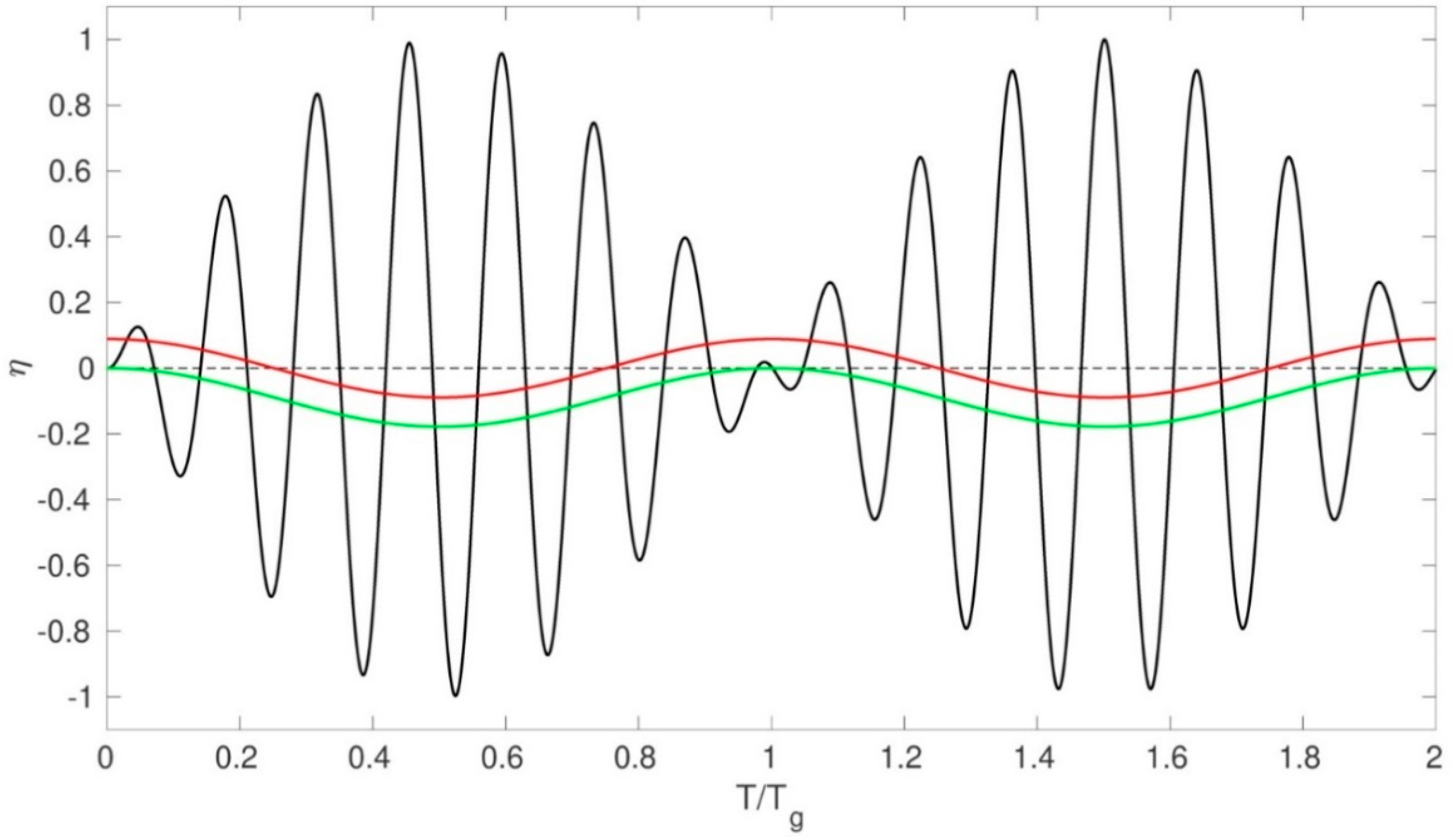
1]. A similar observation from measured data is presented in
Figure 2, but for an individual wave group from a random wave case from Baldock and Huntley [
25]. The lag of the long wave relative to the short wave envelope is also very small in this case, but appears larger in the time domain than in the space domain. It is important to note that these data were obtained with 2nd order generation, which minimises the generation of free (error) waves at the wavemaker (see Orzaghova et al., [
26] for other examples).
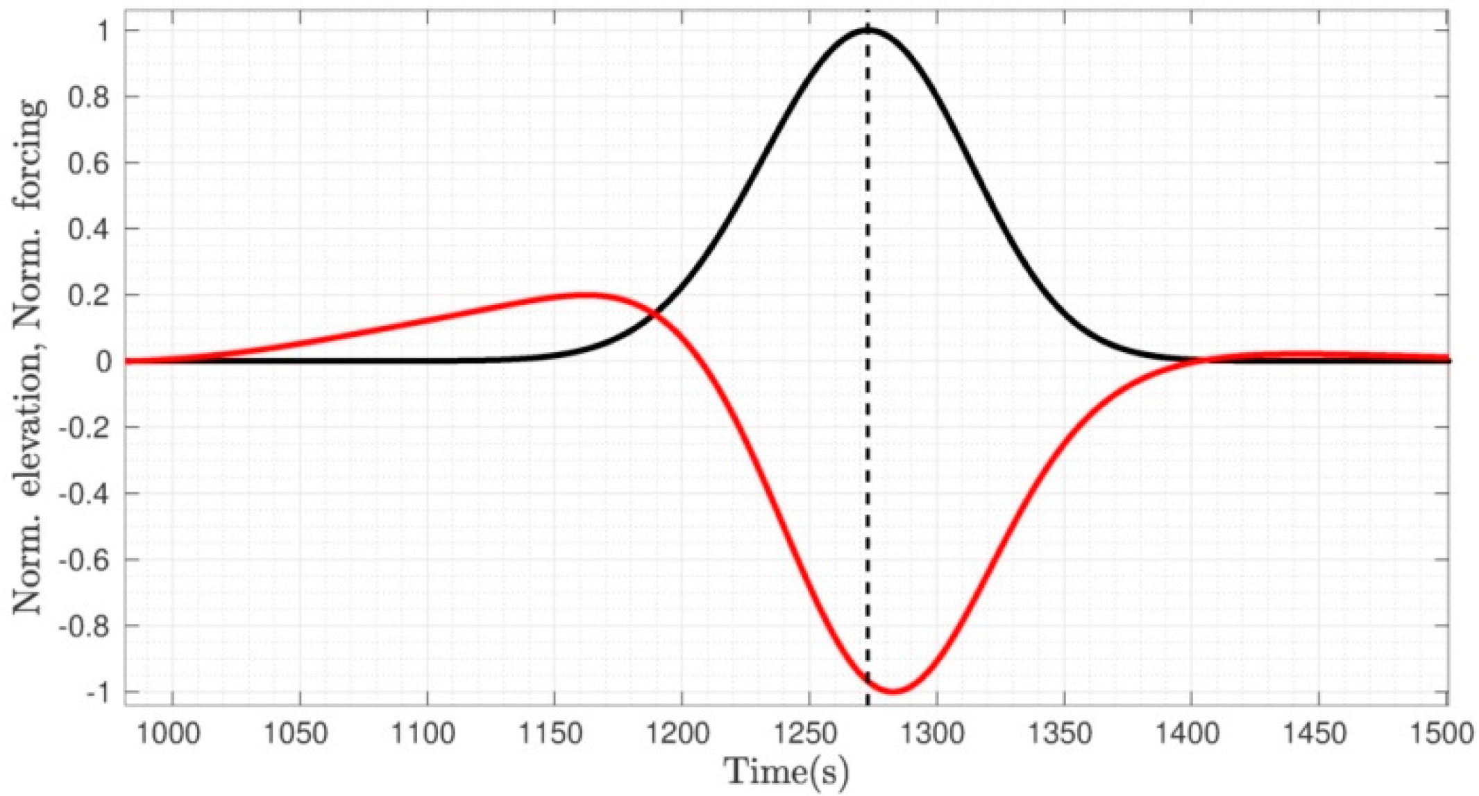
The relationship between the wave envelope and the bound wave is commonly analysed based on time series from a point measurement. This is despite the fact that because the propagating wave group is not steady and not symmetric during shoaling the wave shape measured in the time domain is not the same as the instantaneous shape observed in the space domain, see direct comparisons by Baldock [
11] and
Figure 2 below. In the left panel in
Figure 2 the long wave is in antiphase with the forcing and both are asymmetric. In the right panel, no larger leading wave is observed, even though this is present in the left panel, which means that wave only is generated or amplified very close to the shore, in shallow water. With measurements in the time domain, lags between the forcing and bound wave are often reported [
22,
27,
28]. That occurs even when no lag is observed in the spatial domain (
Figure 2).
In a time series analysis, the bound wave lag is often associated with the intensity of energy transfer from the forcing to the long wave, where a greater lag means more energy transfer. For the same beach slope, higher frequency bound waves appear to lag more than lower frequency bound waves, resulting in higher shoaling rates at higher frequencies. This difference in shoaling rates is clearly evident in data from Baldock et al. [
24] and Janssen et al. [
12]. Battjes et al. [
13] showed that this shoaling rate is determined by the wave group length relative to the bottom slope, a normalised beach slope, varying from approximately ~
(free wave shoaling rate) for relatively lower frequencies to ~
(steady solution shoaling rate) for relatively higher frequencies. It is noted that the shoaling at higher frequencies corresponds to the amplitude growth proposed for the quasi-steady solution of Longuet-Higgins and Stewart [
1,
29], despite no energy transfer or lag being proposed at that time.
In the literature, two terms in the energy balance equation are relevant for modelling the energy exchanges between short and long waves. To the authors’ understanding there are still some difficulties in the interpretation of their role in the energy transfer from short to bound waves. The problem has been introduced by Longuet-Higgins and Stewart [
1,
29], followed by Whitham [
5], who attempted to clarify the issue addressed by the previous authors. In the full energy balance introduced by Philips [
30] and Schaffer [
3], and using their notation for clarity, the conservation of total energy is given by
where E is the total energy density and W is the total energy flux. The short wave energy equation is
where subscript
s and
c denote the short and long waves (current) respectively. The equation for the free slow varying current or long wave is
The two terms related to energy transfer between short wave (via
) and long waves, with U as the bound long wave velocity (equivalent to
in (2) and (3) are
While Battjes et al. [
13] have considered
as the main driver of energy transfer, Henderson et al. [
31], Guedes et al. [
32] and others considered (7) as the principal mechanism. Schaffer [
3] (see page 564), taking in consideration free and forced long waves, suggested (6) as being the interaction between
and the forced wave current, and (7) as the interaction between
and the free current (free long waves). When considering the short wave and free current (tide) interaction (7) was the only term considered by Longuet-Higgins and Stewart [
29], with the forced bound wave being a product of that interaction.
Janssen et al. [
12], following the work of Bowers [
33] and Van Leeuwen [
34], presented analytical and numerical solutions for the bound wave amplitude and phase shift induced by changes in depth. Battjes et al. [
13], assuming quasi-steady waves, derived a phase-average rate of energy transfer based on the phase lag between the wave envelope and the forced wave (
- the deviation from the equilibrium solution, π), the amplitudes of radiation stress (
) and the forced long wave velocity (
)
where
is the forced wave number, at individual frequencies,
, and (ˆ) denotes real amplitudes. Good agreement between this model and laboratory data was found.
Generally, the discussion regarding bound wave shoaling requires the assumption of steady wave conditions, even though the possibility of free wave generation during the shoaling process is recognized in some studies. With a dynamic process, Nagase and Mizuguchi [
21] suggested that the observed smaller growth rate compared to the steady solution of Longuet-Higgins and Stewart [
1] of the bound wave is a consequence of the superposition of forced and free waves generated due to the transient behaviour of the bound (forced) wave on the slope, which is similar to the suggestion of Nielsen and Baldock [
8]. Based on this assumption, even if the shoaling of the forced wave part is independent of the wave group frequency and follows the equilibrium solution, due to the superposition of forced and free waves, an apparent distinct rate of energy transfer (as defined by the rate of change of the total wave amplitude) would exist for wave groups with different length and the same group velocity,
. The apparent lag of the negative pulse would also depend on the group frequency.
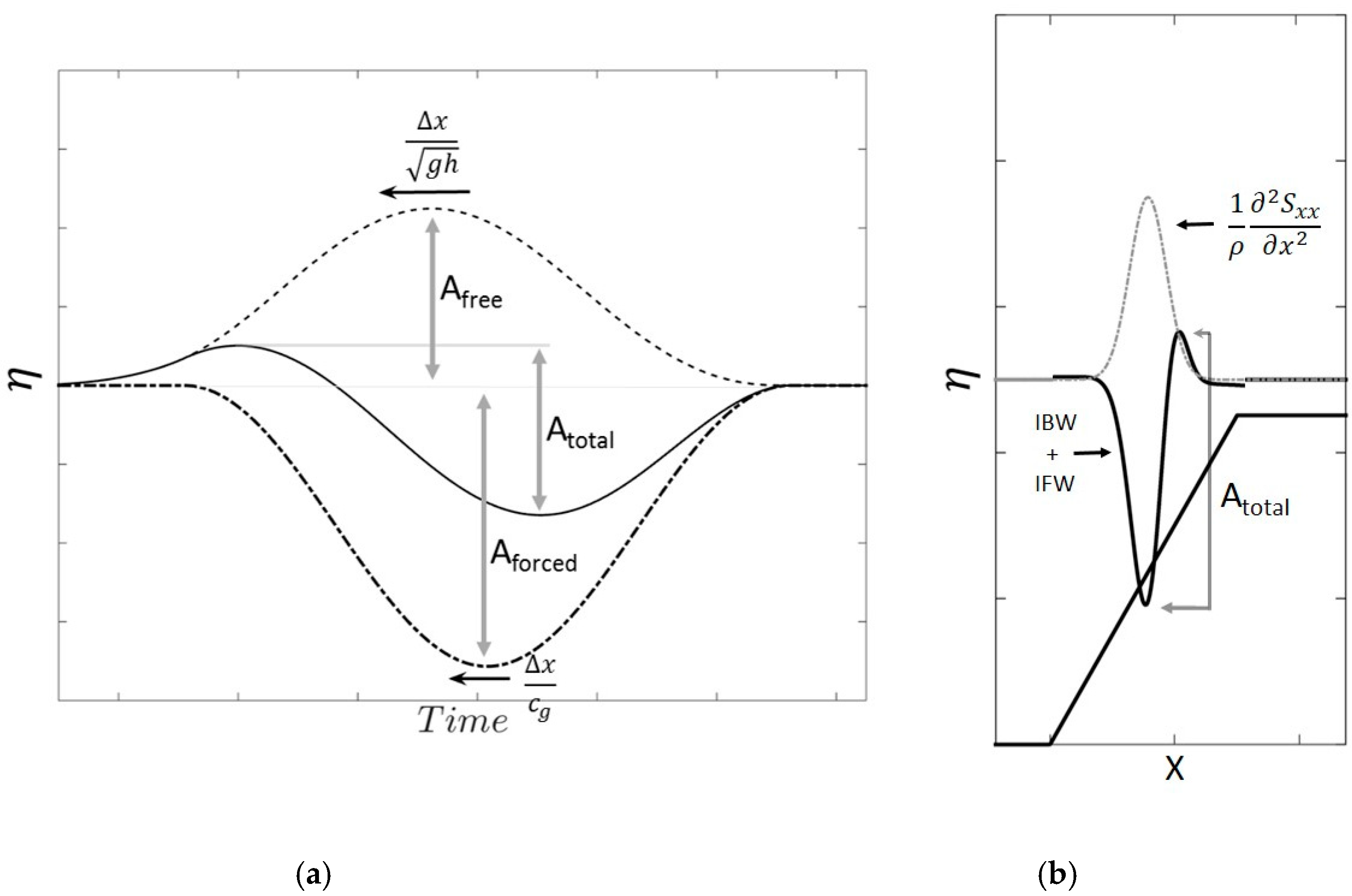
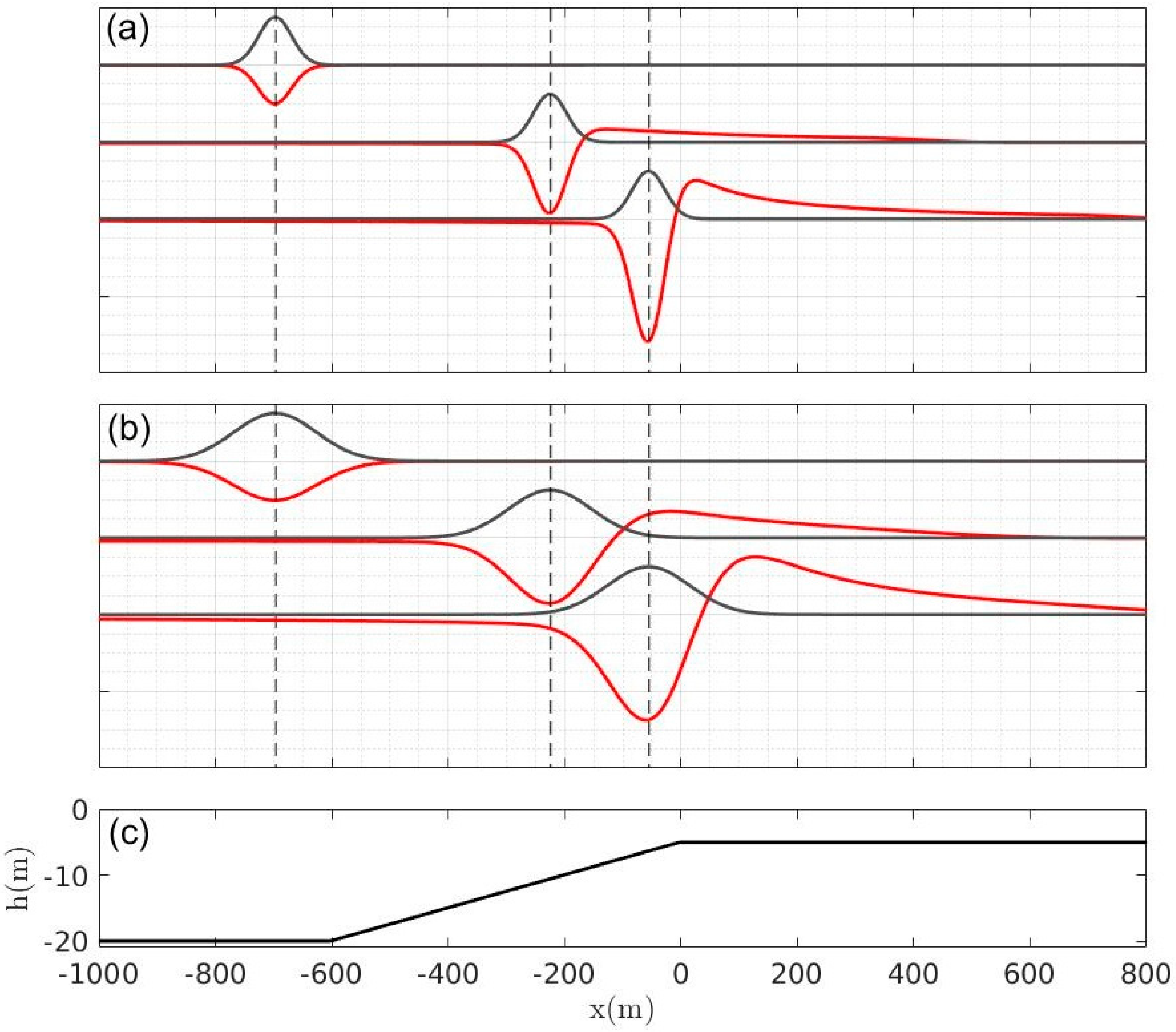
Using the conceptual models of Nagase and Mizuguchi and Nielsen and Baldock, it is straightforward to calculate the evolution of the total long wave expected from superposition of propagating forced wave and free long waves, as illustrated in
Figure 3. Consider a Gaussian-shaped forced wave with amplitude
A and length (
Lscale) with its center location at
xi
propagating with constant form over a slope, and with an increasing amplitude proportional to
(a shoaling rate proportional to the equilibrium solution), where
x is the horizontal distance. At each new time step, the gain in amplitude by the bound wave (an increasing negative depression) is added to the forward free wave as a positive elevation with same shape as (9), which is shoaling also as a free wave (
), to ensure continuity (1). The Gaussian depression is traveling at slower velocity, at the wave group velocity
cg, which is defined in terms of the short wave period
T and wave number
k,
while the positive free wave travels faster, following the shallow water wave velocity (
). Therefore, the two sets of waves slowly separate. This conceptual model is designed by adopting the definition of the forced wave proposed by Mei [
2] (right panel of
Figure 1). The definition by Longuet-Higgins and Stewart [
1] would not necessarily require a positive free wave to balance the increasing magnitude of the forced wave depression. The results show that for groups with the same mean primary wave frequency (i.e., the same group velocity), the gain (change in the crest to trough height) and phase (lag of the long wave trough relative to the forcing) of the total infragravity wave varies with the group frequency.
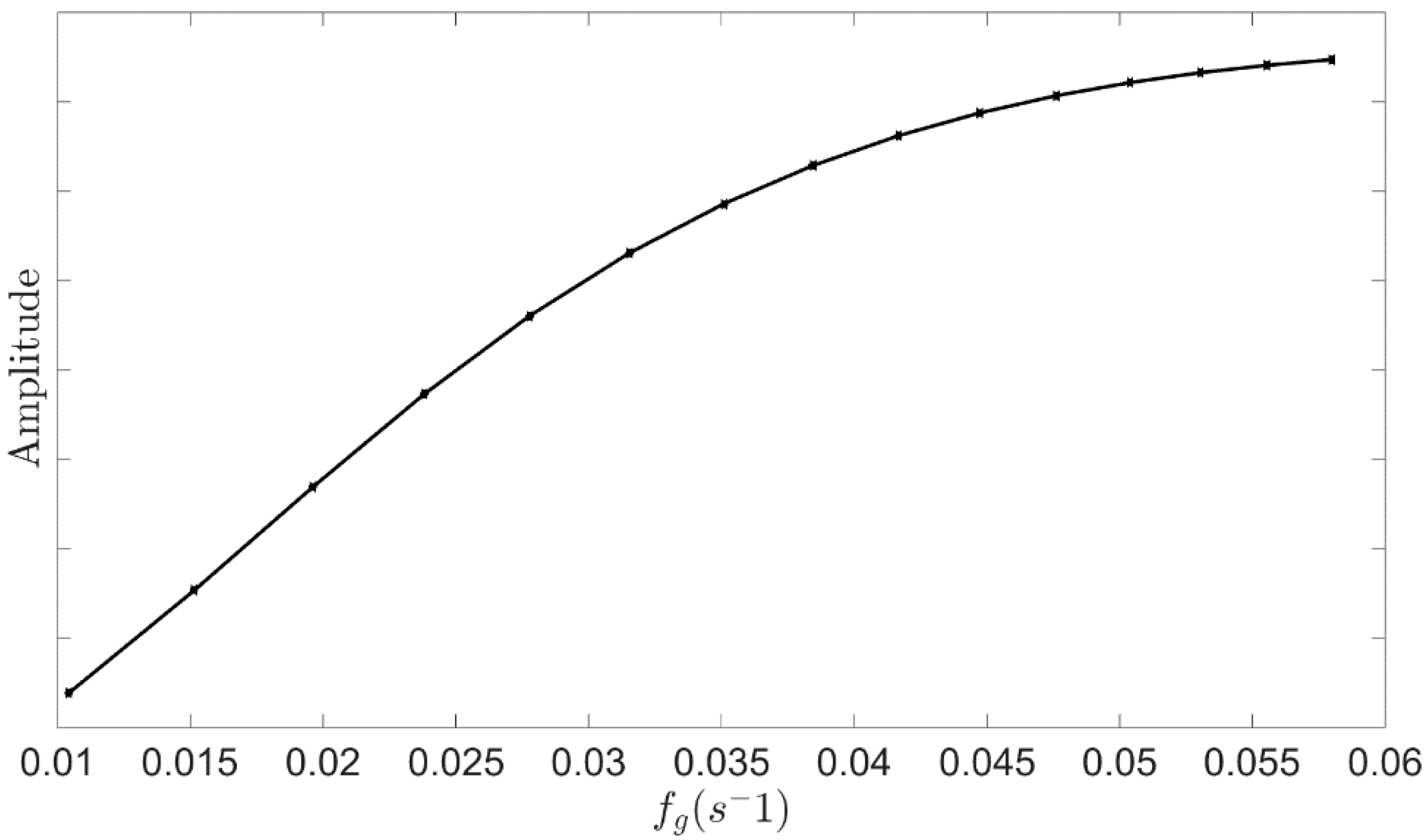
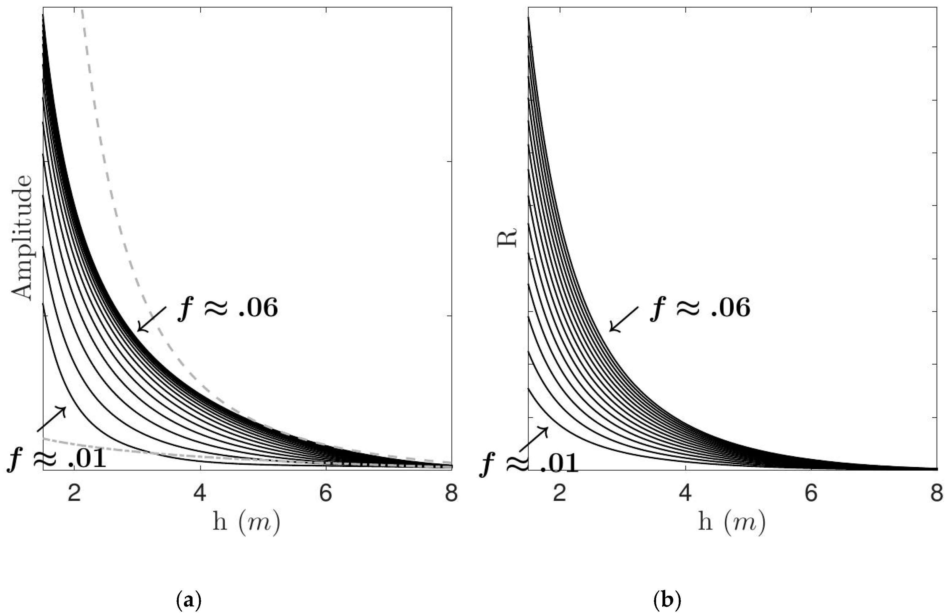
Thus, even though the forced bound wave shoaling is the same as the equilibrium solution, an apparent frequency dependence appears in the shoaling rate of the total long wave. This is illustrated in
Figure 4, which shows how frequency influences the total infragravity wave amplitude at a fixed position on the virtual slope. The results are qualitatively similar to the numerical results in Madsen et al. [
23], their Figure 20, obtained from a Boussinesq wave model with improved dispersion in deeper water.
In this model approach, the only factor affecting the apparent changes in the shoaling rate of the total infragravity wave is the behaviour of the free wave relative to the wave group (forced wave, Equation (9). Over the same distance, the free waves generated by shorter wave groups will tend to propagate further apart from the bound wave than the free waves generated by longer wave groups, since the difference in phase speed between the forced wave and the free long wave is greater. In addition, for a longer group, the free wave needs to travel a longer distance to get ahead of the bound wave. Note that due to the difference between the free wave speed
and group velocity,
, a lag is expected for the total long wave (
Figure 3a) and the magnitude varies according to the length of the forcing. Interestingly, the lags are also only observed in the time domain, not in the space domain. This is consistent with the observations of Baldock [
11] and also with the data in
Figure 2.
Based on these lags, hypothetical rates of energy transfer are calculated using Equation (8). As illustrated in
Figure 5, the apparent rate of energy transfer also seems to increase with increasing frequency of the forced wave. This is the same behaviour as that predicted by the energy transfer model of Janssen et al. [
12]. The apparent shoaling rate for the long wave groups are closer to
, i.e., similar to free long waves, while short groups are closer to
, qualitatively matching the different shoaling behavior in the mild-slope and the steep-slope regimes described by Battjes et al. [
13]. The results presented for this conceptual model are quite simple, but they indicate that adding free waves into the bound wave shoaling process may change the results and therefore the interpretation of energy transfers, and phase lags of the forced wave.
In order to verify this hypothesis a set of simulations using the COULWAVE model [
35] which adopts the fully nonlinear Boussinesq equations, is presented. This model is widely used for wave modelling and has been well-verified in previous studies, including surf beat studies [
36]. The model solves the conservative form of weakly dispersive and fully nonlinear Boussinesq equations in 1-D, following [
37]
where
is the total water depth,
is the surface elevation, h water depth,
velocity at water depth
and
are the higher order terms that include bottom turbulence and dispersive properties and
is the wave breaking dissipation term. The simulations are performed introducing the radiation stress forcing term into the momentum Equation (12), using the right hand term in Equation (1), as the driving mechanism of bound wave generation, with radiation of free waves (4) as required to ensure continuity. Following Nielsen and Baldock [
8], seven cases of Gaussian-shaped wave group envelopes, similar to Equation (8), with the same primary mean wave period of
(and the same group velocity, Equation (9)), but different group lengths, varying from 200
to 345
, are tested. The domain starts with a long section of horizontal bottom (
) connected to a slope (
) followed by a long plateau (
), similar to
Figure 3b. The length of the plateau is sufficient for the free waves, generated during the shoaling process, to propagate completely away from the forced waves so that the different waves are separated in space and time. The initial condition is flat water, with the forced wave at the initial time-step balanced by the two free waves as proposed by Nielsen and Baldock [
8]. The length of the initial horizontal domain is also sufficient so the free waves propagate completely away from the forcing region, such that when the forcing zone propagates to the start of the sloping beach, only the forced wave remains as a pure depression, representing the conditions proposed in the model of Mei [
2] (
Figure 1b).
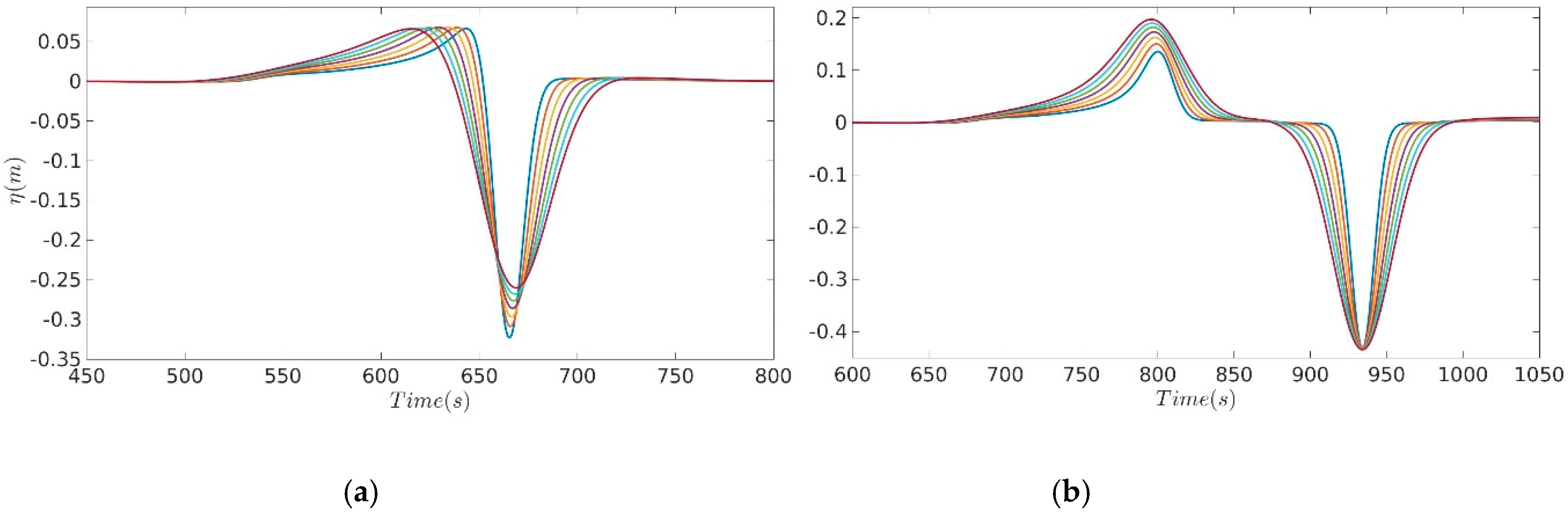
Similar to the results from the conceptual model,
Figure 5, these specific examples,
Figure 6, show that in the shoaling zone the shorter infragravity waves have larger apparent amplitudes than the longer infragravity waves. Also, the shorter the long wave, the greater is the apparent lag with respect to the forcing. However, after the forcing reaches the constant depth plateau, the shoaling stops and the free waves propagate away ahead of the forcing region, leaving behind only forced waves, which all have with same amplitude. The differences in amplitude of the leading free waves at around t ≈ 800 s on the plateau,
Figure 6b, are due to the different lengths of the forcing relative to the length of the slope where the changes are occurring, with shorter groups resulting in a smaller free wave amplitude.
The numerical calculations for these same specific examples also show that for all cases no lag occurs in the spatial domain between the forcing and the bound wave (see
Figure 7) but that a lag is observed in the time domain (
Figure 8), similar to that observed in the laboratory data (
Figure 3). The difference between observations in the spatial domain and the time domain is important, since most measurements of the bound wave lag occur from data obtained in the time-domain. In this model, the forced wave part of the total wave is by definition in antiphase with the forcing, so it does not lag the forcing. However, since the system is unsteady and evolving as the wave passes a fixed location, the total solution has an apparent lag in the time domain. Overall, the results suggests that when considering the approach of Mei [
2] (
Figure 1b) for the bound wave problem via radiation stress forcing, both the shape and shoaling rates could be affected by the generation of positive leading free waves required to balance the shoaling forced wave. Further investigation is needed in order to verify if free waves generation occurs in laboratory or natural conditions. This is difficult, since long spatial domains are required to observe separation of free and forced waves with very similar celerity. Indeed, in shallow water the waves do not separate at all.
3. Bound Wave Dissipation after Short Wave Breaking
One important question yet to be fully answered is what happens to the bound wave after short wave breaking? Different datasets indicate bound wave release [
12,
13], while others indicate dissipation of the forced wave in the surf zone [
17,
24,
36,
38]. Baldock [
15] suggested that the relationship between short and infragravity wave with water depth at the breakpoint is important to determine whether the bound wave is released or if it remains forced, decaying with the dissipation of the short waves. During the breaking process, three different conditions are possible: (i) at the breaking point both the short and forced waves are not in shallow water,
and the length of the bound wave is not much longer than
h; (ii) the bound wave is much longer than
h, but the short waves are not, hence the bound wave number differs from the wave number of a free wave with same frequency; (iii) both short and bound wave are in shallow water at the break point. Bound wave release is considered to occur when both short and bound waves are in shallow waters, therefore being strictly valid only for the third condition. While the first possibility is more likely for deep-water wave breaking, the second condition can occur at the edge of the surf zone, especially during storm conditions [
15].
Baldock and O’Hare [
39] compared the behaviour of free non-breaking waves and forced infragravity waves inside the surf zone. The laboratory experiment was designed so the effects of short wave breaking on forced and free waves could be evaluated. With one set of cases based on two free waves, a short breaking wave and a smaller and longer non-breaking wave; and a second set of cases based on fully modulated bichromatic groups. The results have shown that while small or nearly no dissipation occurred for the free non-breaking waves, strong dissipation occurred for short bound waves starting at the break point. The authors then observed that the short wave breaking was occurring when the waves were not in shallow water, justifying the forced wave decay in the surf zone. The numerical investigation presented in Moura and Baldock [
36] showed, for the same cases, that no significant breakpoint excursion occurs at the group frequencies, therefore there was no breakpoint forcing at these frequencies. This removes the possibility of interference between the bound wave and breakpoint force long waves, which has been previously suggested as an explanation for the infragravity wave amplitude decay in the surf zone [
3].
In order to test whether the breaking depth affects the behaviour of the bound wave, the simulations using the COULWAVE model for two fully-modulated bichromatic cases presented by Moura and Baldock [
36] are extended to a larger range of wave conditions, where the amplitude of the fully-modulated wave groups are progressively reduced, hence shifting the break point to shallower water. The COULWAVE model has two options to simulate wave breaking, the eddy viscosity model described in Kennedy et al. [
40] and an adaptation to this model, named the transport-based model [
41], which is the one selected for this study. Both models use the same eddy viscosity dissipation term and a triggering mechanism (local time derivative of the surface elevation exceeding a threshold) to initiate wave breaking. For further details of the modelling see Moura [
42]. For both cases, strong bound wave dissipation, starting at the edge of the surf zone, have been observed in the data [
24] and reproduced numerically [
36]. The numerical results in
Figure 9 indicate that independently of the water depth at the short wave breakpoint the bound wave is dissipated from the breakpoint up to the swash zone. The small outgoing waves corroborate that the bound wave dissipation occurs for all tested cases. This means that when short wave breaking occurs in shallow water, and hence bound wave release is expected, strong dissipation is still occurring. This implies that the energy dissipation is due to turbulence generated by the short waves. This supports the suggestion of Battjes et al. [
13], who proposed that infragravity waves that are relatively short compared to the surf zone width are more easily dissipated than longer waves whose its lengths are only a fraction of the surf zone. Hence, dissipation is also strongly frequency dependent.
To extend this analysis further, using the COULWAVE model, and following the experiment layout in Baldock and O’Hare [
39], the effects of a surf zone on the dissipation of non-breaking free long waves is numerically investigated by two sets of simulations, with and without a surf zone. The first set of simulations with a surf zone comprise of a short breaking monochromatic wave (
w1) with an amplitude of 5 cm and frequency of 0.8 Hz paired with longer free monochromatic waves (
w2) with an amplitude of 0.05 cm and frequencies varying from 0.09 to 0.5 Hz, to represent free long waves inside a surf zone. The second set of simulations comprised of the same monochromatic free long waves (
w2) but with no short waves and hence no surf zone. The model results for the long waves (
w2) with and without a surf zone are then compared in terms of total, incident and outgoing wave amplitude.
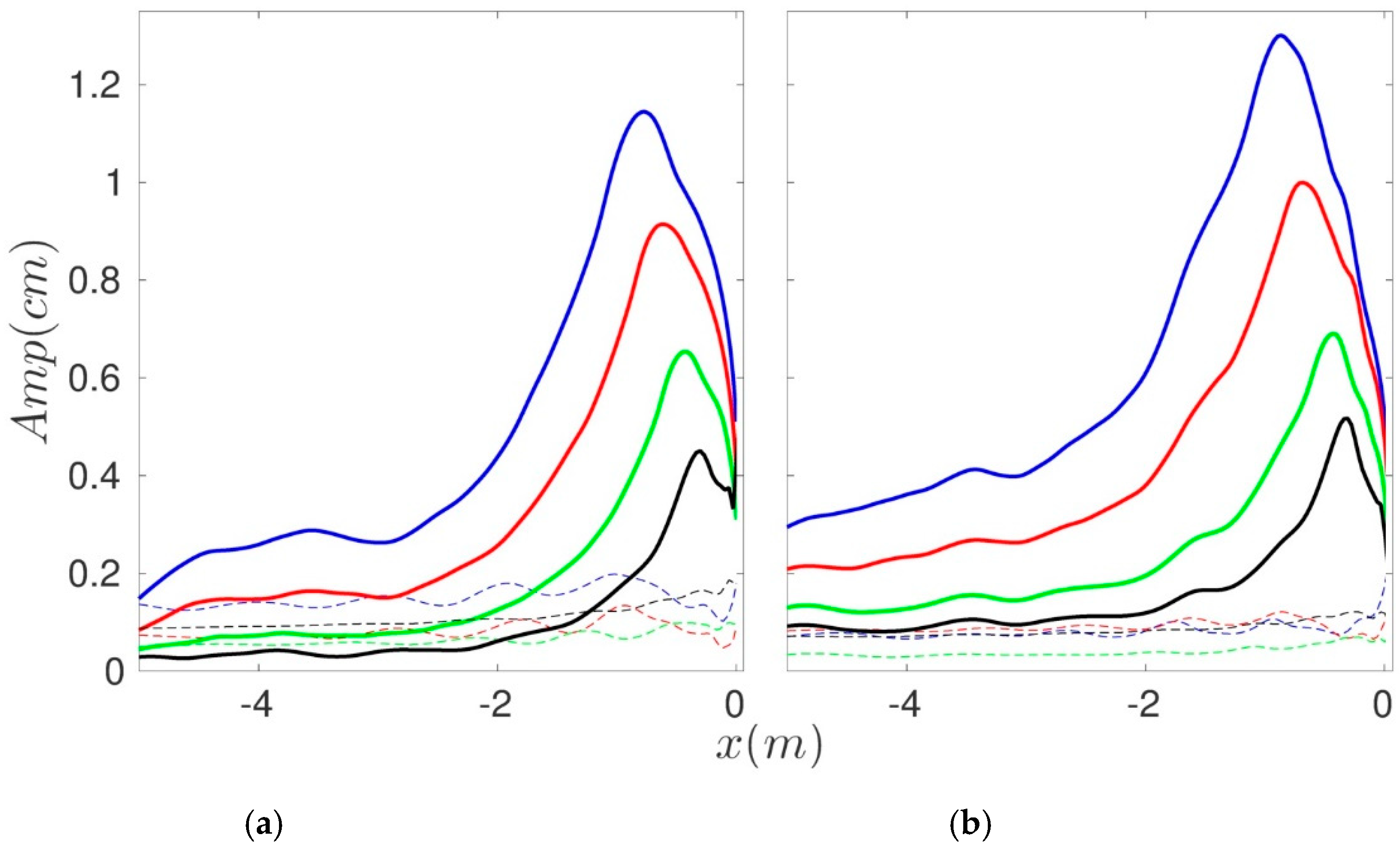
The standing wave total amplitude patterns generated by
w2 in the absence or presence of a surf zone are significantly different (
Figure 10). While for both scenario a reduction of the nodal structures occurs towards the higher frequencies, the process is intensified for the cases with a surf zone present. Thus, dissipation of free long waves by eddy turbulence inside a surf zone is certainly frequency dependent based on the COULWAVE model, and it is likely this explains the decay of the incident forced wave also, as proposed by Battjes et al. [
13], with some additional reduction in amplitude since the forcing is also being reduced by short wave breaking.


