Article

Tripod-Supported Offshore Wind Turbines: Modal and Coupled Analysis and a Parametric Study Using X-SEA and FAST

1
Department of Civil and Environmental Engineering, Konkuk University, 120 Neungdong-ro, Seoul 05029, Korea
2
MaREI Centre for Marine and Renewable Energy, ERI, University College Cork, P43C573 Cork, Ireland
*
Author to whom correspondence should be addressed.
J. Mar. Sci. Eng. 2019, 7(6), 181; https://doi.org/10.3390/jmse7060181
Submission received: 16 May 2019 / Revised: 29 May 2019 / Accepted: 31 May 2019 / Published: 9 June 2019
(This article belongs to the Special Issue Marine Structures)

Abstract

:
This paper presents theoretical aspects and an extensive numerical study of the coupled analysis of tripod support structures for offshore wind turbines (OWTs) by using X-SEA and FAST v8 programs. In a number of site conditions such as extreme and longer period waves, fast installation, and lighter foundations, tripod structures are more advantageous than monopile and jacket structures. In the implemented dynamic coupled analysis, the sub-structural module in FAST was replaced by the X-SEA offshore substructure analysis component. The time-histories of the reaction forces and the turbine loads were then calculated. The results obtained from X-SEA and from FAST were in good agreement. The pile-soil-structure interaction (PSSI) was included for reliable evaluation of OWT structural systems. The superelement concept was introduced to reduce the computational time. Modal, coupled and uncoupled analyses of the NREL 5MW OWT-tripod support structure including PSSI were carried out and the discussions on the natural frequencies, mode shapes and resulted displacements are presented. Compared to the uncoupled models, the physical interaction between the tower and the support structure in the coupled models resulted in smaller responses. Compared to the fixed support structures, i.e., when PSSI is not included, the piled-support structure has lower natural frequencies and larger responses attributed to its actual flexibility. The models using pile superelements are computationally efficient and give results that are identical to the common finite element models.

1. Introduction

Among the common types of fixed-bottom substructures, shown in Figure 1, monopile structures are most suitable for regions with shallow water depths (less than 30 m) [1]. Tripod and jacket structures can be constructed in transitional water depths (between 30 and 50 m). An alternative design that makes use of the various advantages of both monopile and jacket structures is known as the tripod support structure. The main part consists of a mono pile tubular section and the lower part consists of braces and three legs. Compared to a standard lattice structure, the tripod support structure is considered to be a relatively lightweight three-legged steel jacket. The central column beneath the tower and turbine transfers the forces from the tower into the three inclined members. In order to anchor the tripod to the seabed, piles are usually installed at each leg position. Suction caisson [2,3] and suction buckets [4] can be used to support the tripod structures, which have good stability and overall stiffness.
Although the jacket foundation concept is preferable to the tripod concept in terms of scour, ship collision, complexity of joints and deflection at tower top [5], the stiffer tripods are less resonant with waves and provide more opportunities to tune the natural frequency [6]. This becomes more profound as the turbines get higher; the natural frequencies of the tower-support structure system decrease and may match the high energy part of the wave spectrum [6]. Tripod support structures are therefore a good option for transitional water regions that have extreme wave conditions or long wave periods.
A tripod suction caisson foundation has been adopted by Korea’s second Herald of Meteorological and Oceanographic Special Research Unit (HeMOSU-2) [2,3] after a jacket pile substructure was used for the HeMOSU-1 [7]. The construction cost of the tripod suction caisson foundation is only half that of the jacket piles for the same seabed geology, according to the cost analysis for HeMOSU-2 [2]. Additionally, installing HeMOSU-2 with a tripod suction caisson foundation took only 6 h to complete, while two months were required for the installation of HeMOSU-1 [2,3]. In terms of construction and installation, suction caissons appear to be an excellent solution.
Compared to monopile, suction bucket and gravity-based structures, the piled tripod is the lightest support structure because of its light foundation piles [6]. If the manufacturing process of the tripods, which requires more space than the monopiles, can be optimized, the use of piled tripods is more beneficial. Besides that, the types and sizes of conventional offshore structures, whose installation is currently routine are similar to those of tripod piles. Monopiles supporting 6 MW or larger wind turbines must have much larger diameters than the current piles, which causes practical problems including the lack of sufficiently heavy hammers [6]. Similar to jacket foundations, the global moments in tripods are dissolved into pairs of forces that are transferred as axial loads to the soil. Thus, tripods are especially advantageous in weak soils compared to monopiles, which transfer the lateral and moment loads by bending to the soil [5]. In a comparison study on the structural properties of monopile and tripod support structures for offshore wind-turbines [8], tripods exhibited higher stiffness, greater stress-control capacity, and a longer lifetime than monopiles. If the challenges related to tripods, such as the complex joints required to connect the three legs to the upper monopile and their susceptibility to fatigue damage can be overcome, tripod foundations could be a better alternative to monopiles in transitional water depths of around 30 m.
As discussed, tripod support structures are more advantageous than monopile and jacket structures in a number of site and installation conditions. In terms of geotechnical aspects, the group effect [4] and combined horizontal-moment bearing capacities of tripod bucket foundations in clay [9] and in sand [10] have been investigated by using advanced three-dimensional (3D) finite element analysis. Parametric studies were carried out by varying the spacing between each bucket foundation, embedded depths and loading directions [4]. In terms of structural aspects, static and modal analyses have been used to study the structural properties of tripod support structures for offshore wind-turbines [8]. A finite element model of a tripod substructure was constructed for global optimization of the best design considering uncertainties [11]. In a recent design of tripod foundation, the superstructure of the turbine was first simulated under wind and wave dynamic loading using FAST (Fatigue, Aerodynamic, Structures and Turbulence)—a CAE tool developed by the National Renewable Energy Laboratory (NREL), USA, to obtain time histories of internal actions for the pylons [12] using 3D finite element analysis software. These iterative analyses were utilized to obtain the required pile lengths and cross sections for tripod options [12]. However, the structural analyses and design of tripod support structures under simultaneous action of various environmental and operational conditions are less reported in the literature.
As soil models are generally complicated and are very expensive in terms of computing time [13], the simulation codes for offshore wind turbines often exclude the detailed modeling of soil-structure interaction [14]. Simpler approaches have therefore been adopted in the literature or the assumption of a support structure clamped at the seabed has been used [13]. A coupled, linear approach with six directions and soil-structure interaction matrices was introduced to modify the FAST simulation code [13]. The dynamic soil properties obtained by comparing nonlinear spring models of soils and experimental results were then incorporated [14]. Moreover, an offshore wind turbine (OWT) support structure must withstand the environmental and operational loading without failure. The behavior of the surface layer of soft, poorly consolidated marine clays and the stiffer clay or sand strata under this loading, and their influence on the responses of the foundation-turbine system are also important considerations. An analysis approach that considers the simultaneous interaction among the turbine, the tower, the support structure and the soil layers, the so-called coupled analysis, is required to ensure the safety of all structural components and the serviceability of the OWT system [15]. However, lengthy computation time for the coupled analysis of complex systems is an issue [16].
This paper therefore addresses the lack of coupled analysis of tripod support structures for offshore wind turbines under the simultaneous actions of various environmental and operational conditions, and develops efficient measures to reduce the computation times of the coupled analysis. In order to reduce the excessive computation times for the coupled analysis of a complex offshore support structure—a wind turbine—the superelement modeling technique was combined with the modal truncation augmentation concept by using the Craig–Bampton (C-B) method [17]. The procedure for dynamic coupled analysis proposed in this study was implemented in the X-SEA program, a 3-D finite element analysis software developed by the authors for the analysis and design of fixed and floating offshore structures for the oil/gas and offshore wind energy industry [18,19]. The procedure was validated by FAST v8 [20]. Theoretical aspects of the coupled analysis approach using X-SEA were initially discussed in the study of jacket structures [21] and are extensively described in this paper for tripod support structures. The soil-pile-structure interaction formulation was included in the implementation. However, the differences in soil conditions among the supports [22], the seismic loading [23,24], and the combination of seismic and aerodynamic loading [25] will be considered in a future study. The displacements resulting from the coupled analysis of the tripod structure are compared with that from the uncoupled analysis. A parametric study of an NREL 5MW OWT supported by a tripod structure using coupled analysis with soil-pile interactions is also carried out.

2. Development of Coupled Analysis for OWT and Tripod Support Structures

For simulating the coupled dynamic response of onshore, offshore fixed-bottom and floating wind turbines, a Glue-Code joins hydrodynamic, structure dynamic, SeveroDyn or electronic, aerodynamic, and structure modules, which are used in the FAST program [20] as depicted in Figure 2. This is an open source program and enables coupled nonlinear simulation in the time domain and the analysis of a range of wind turbine configurations. However, its hydrodynamic and structural element concepts were limited to the engineering field. Hence, the 3D finite element analysis software X-SEA was developed in Konkuk University, Seoul, Korea to solve several types of offshore wind structures [26]. The solution options of X-SEA range from simple static to highly advanced nonlinear dynamic analysis. In the case of uncoupled analysis, X-SEA receives the components of forces ( F x , F y and F z ) and moments ( M x , M y and M z ) at the top of the tower from FAST v8 and applies the loads to the support structure as shown in Figure 3a. The coupled analysis, which interchanges modules between the two programs is achieved through a modular interface and coupler as illustrated in Figure 3b.
The coupling of the substructure module in FAST V.8 program is loosened and replaced by that of X-SEA as illustrated in Figure 4. At the exchange position, the eighteen components of motion represented in the displacement { u } , velocity { u ˙ } and acceleration { u ¨ } vectors are the input to the present program from the structural dynamic module in the FAST program. The six components of action FTP from the X-SEA are input to the structural dynamic module in the FAST program.

2.1. Wind Turbine Dynamics

In FAST code, the representations of the modal and multibody system dynamics are combined [20]. Linear modal representation with a small deflection assumption, two flapwise bending modes and one edgewise bending mode per blade are used to model the wind turbine blades. The tower can be modelled by two fore-aft and two side-to-side bending modes. The X-SEA uses the wind turbine dynamics modules in FAST v8. When the aerodynamic module, AeroDyn is coupled to FAST, the wind profile and structural motions are inputted at each coupling time step. In the aero-elastic calculation, the aerodynamic loads on the blade and tower nodes are computed by AeroDyn and returned back to FAST.

2.2. Structural Dynamics of Substructures

The platform has full six degrees-of-freedom (DOF) with flexible body motion based on the X-SEA structural frame elements. X-SEA is the software used for integrated finite element structural analysis, which provides the nonlinear dynamic analysis and design of offshore steel and concrete structures, including oil and gas platforms and offshore wind farms [18,19]. The current version of X-SEA V3.04 is the result of extensive research and development of the finite element program XFINAS [27], originally developed at Imperial College, London. The solution options of X-SEA range from simple static to highly advanced dynamic analysis using Morison equation and diffraction theory [19,21]. The Element Library in X-SEA consists of various element types essential to the modelling of offshore structures and foundations such as shell, solid, truss, cable, spring and tendon elements [21]. By using the pre/post processor software, GiD, a user-friendly graphical interface of FAST was developed for the calculation of wind turbine loading.

2.3. Hydrodynamics in X-SEA

The dynamic response of fixed offshore structures can be carried out by using X-SEA hydrodynamic modules, which includes Airy wave, Stokes 5th, Cnoidal wave, Solitary wave, and Stream functions. The Morison equation is used to compute hydrodynamic forces with contributions including hydrodynamic added mass and damping, and incident wave excitations [28]. For a single pile, the motion equation in terms of mass (m), damping (c) and stiffness (k) that is limited by the assumptions mentioned above is
( m + m ˜ ) w ¨ + ( c + c ˜ ) w ˙ + k w = 1 2 C D ρ A | v | v + C M ρ Δ v t
where the parameter ρ is a water density, C D and C M are drag and inertia coefficients, respectively, and v is the velocity of the water particle acting on the structural node and normal to the structure. The term A is the cross-sectional area of the element, and Δ denotes the volume of the displaced fluid. The terms w ¨ , w ˙ and w are the displacement, velocity and acceleration, respectively, of the structure in its local coordinate, which are normal to or in its longitudinal axis. When the motion of the structure is considered, the inertia force is reduced by a factor proportional to the structural acceleration, and the drag force is reduced by the relative velocity and given in the form:
m ˜ = ρ ( C M 1 ) Δ c ˜ = C D ρ A v ¯
in which, v ¯ is time-dependent cylinder velocity [26]. The terms in Equation (1) obtained in structure local coordinates are then transformed to the global coordinates depicted in Figure 3. When the diameter (D) of the cross section in the structure are considerably large in comparison with the wavelength (L), i.e., D/L ≥ 0.2, the Morison theory is considered to be inapplicable [28]. Therefore, a diffraction theory implemented in X-SEA [28] can be considered.

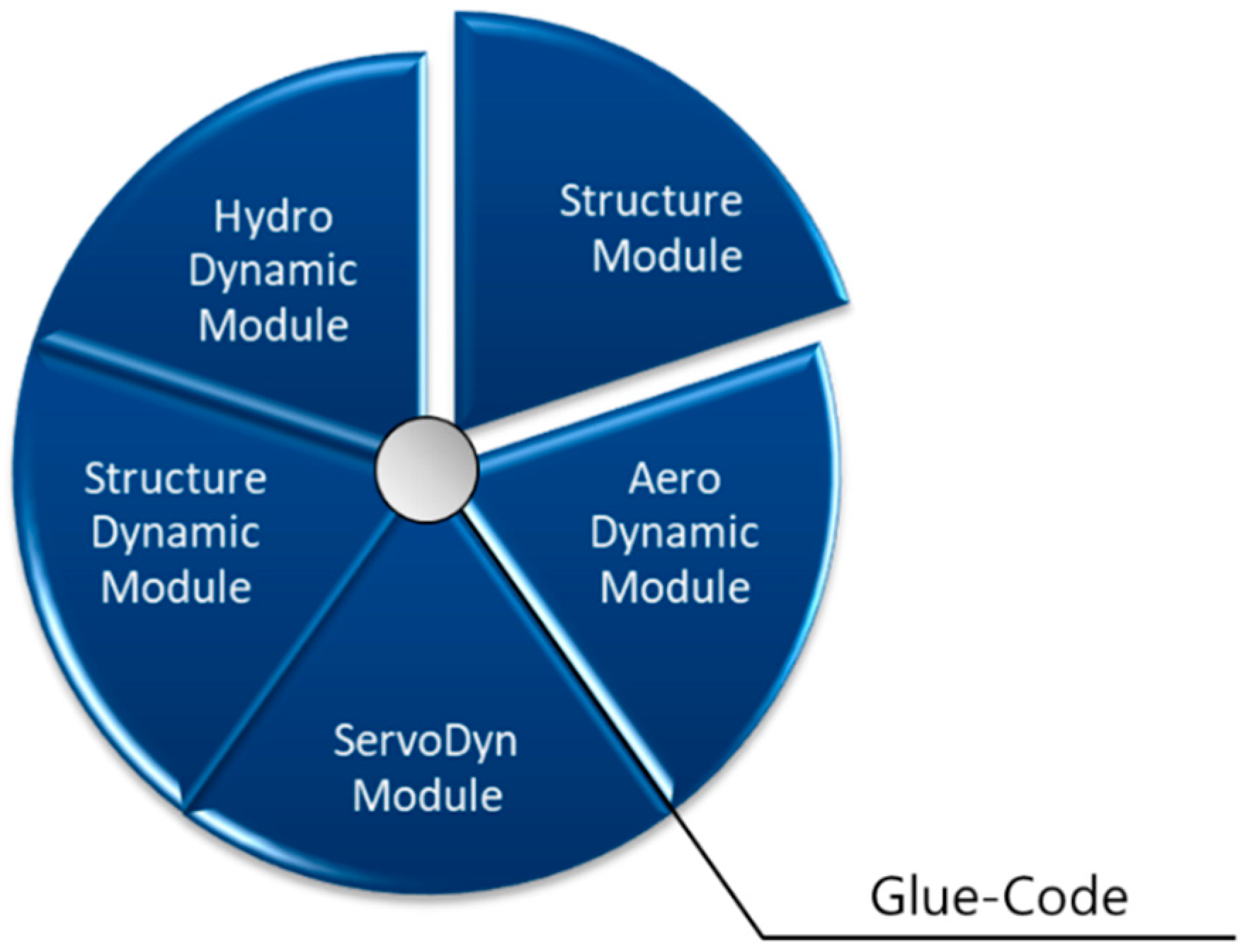
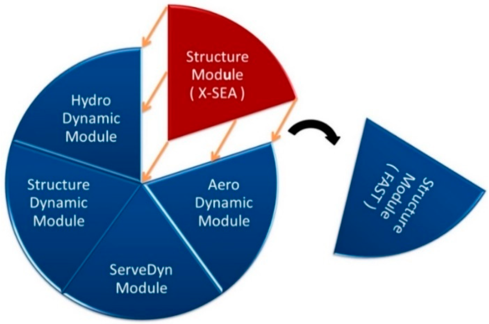
2.4. Coupled Dynamic Analysis of Offshore Wind Turbine and Support Structures

In the simulation and analysis of OWT structures, there are two approaches: uncoupled and coupled methods [24,29]. The uncoupled method is a single way of simulation by transmitting forces and moments from the turbine to the tower or support structure. The interactions among the turbine, the tower and the support structure at the time of analysis were not considered in the uncoupled approach [15]. In order to account for these interactions, the coupled analysis approach is therefore used in this paper. That can be done by following the concept of exchanging displacement ( u ), velocity ( u ˙ ), acceleration ( u ¨ ) and reaction forces ( F T P ) at the interface node as depicted in Figure 3b. The equation of motion of the support structure can be written as
[ M ] { U ¨ } + [ C ] { U ˙ } + [ K ] { U } = { F ( t ) }
The Craig-Bampton (C-B) reduction [17] was introduced by following the FAST program [30]. This is used to reduce the number of degrees of freedom, which easily grow to thousands for the typical frame elements. The nodes were classified into the boundary nodes “S” and the interior nodes “N”. The derivation of the systematic reduction is presented as follows where the reduced equation of motion is:
[ M S S M S N M N S M N N ] { U ¨ S U ¨ N } + [ C S S C S N C N S C N N ] { U ˙ S U ˙ N } + [ K S S K S N K N S K N N ] { U S U N } = { F S + F S g F N + F N g }
The applied forces include the external forces ( F S , F N ) through the interface node of the substructure and the gravitation forces ( F S g , F N g ), which are considered as static forces lumped at each node. The forces at the boundary nodes are separate into the hydrodynamic forces, F H y d r o d y n a m i c and those transferred from the structural dynamic module, F S t r u c t u r a l _ D y n a m i c _ M o d u l e .
F S = F H y d r o d y n a m i c + F S t r u c t u r a l _ D y n a m i c _ M o d u l e
The fundamental assumption of the C-B reduction method is that the nodal displacements can be simply approximated by the interior generalized vector q N as:
{ U S U N } = [ I 0 Φ S Φ N ] { U S q N }
where I is the identity matrix, Φ S is the physical displacement of the interior nodes for static analysis, and Φ N is the internal eigenmode. These can be obtained by:
Φ S = K N N 1 K N S
I = Φ N T M N N Φ N
By reducing the number of generalized displacements to “m”, Φ m is chosen to denote the truncated set of Φ N and Ω m is the diagonal matrix containing the corresponding frequencies. The nodal displacements can be written as:
{ U S U N } = [ I 0 Φ S Φ m ] { U S q m }
The equations of motion finally become:
[ M B B M B m M m B I ] { U ¨ S U ¨ N } + [ C S S + C S N Φ S + Φ S T C N S + Φ S T C N N Φ S C S N Φ m + Φ S T C N N Φ R Φ m T C N S + Φ m T C N N Φ S Φ m T C N N Φ S ] { U ˙ S U ˙ N } + [ K S S 0 0 Ω m 2 ] { U S U N } = { ( F S + F S g ) + Φ m T ( F S + F S g ) Φ m T ( F N + F N g ) }
The matrix partition can be calculated as follows:
M B B = M S S + M S N Φ S + Φ S T M N S + Φ S T M N N Φ S M m B = Φ m T M N S + Φ m T M N N Φ S M B m = M m b T K B B = K S S + K S N Φ S
The fixed boundary condition applied at the bottom of the support structure can be written as:
U S = [ U ¯ S 0 ]
Finally, the interface nodes are treated as rigidly connected to the transition pieces as follows:
U ¯ S = T U T P
where U T P is the displacement and rotation of the interface node or transition piece. The matrix T is the global coordinate due to the interface node and is defined by following the local coordinate system of motion as:
t i = [ 1 0 0 0 Z i Z T P ( Y i Y T P ) 0 1 0 ( Z i Z T P ) 0 X i X T P 0 0 1 Y i Y T P ( X i X T P ) 0 0 0 0 1 0 0 0 0 0 0 1 0 0 0 0 0 0 1 ]
By following the equation of motion in the present program, the velocity, acceleration, and displacement received from FAST program at a time step can be written as:
[ M ] i { U ¨ T P } i + [ C ] i { U ˙ T P } i + [ K ] i { U T P } i = { F ( t ) } i
In Equation (15), i is the interface node number applied to the structure in the present program. In terms of the interface node, the boundary node is classified as “B”. After applying the fixed constraints at those nodes, Equation (10) can be written as:
[ M ˜ B B M ˜ B m M ˜ m B I ] { U ¨ T P q ¨ m } + [ C S S + C S N Φ S + Φ S T C N S + Φ S T C N N Φ S C S N Φ m + Φ S T C N N Φ R Φ m T C N S + Φ m T C N N Φ S Φ m T C N N Φ S ] { U ˙ S q ˙ m } + [ K ˜ S S 0 0 Ω m 2 ] { U T P q m } = { F T P F ˜ m }
where the terms in Equation (16) are defined as:
M ˜ B B = T I T M ¯ B B T I M ˜ m B = T I T M ¯ m B M ˜ B m = M ˜ m b T K ˜ B B = T I T K B B T I F ˜ T P = F T P + T I T F ¯ H D R + T I T F ¯ S g + T I T Φ ¯ S T ( F N + F N g ) F ˜ m = Φ m T ( F N + F N g )
Finally, the force and moment at the interface node can be written as:
F T P = T I T F S t r u c t u r a l _ D y n a m i c _ M o d u l e

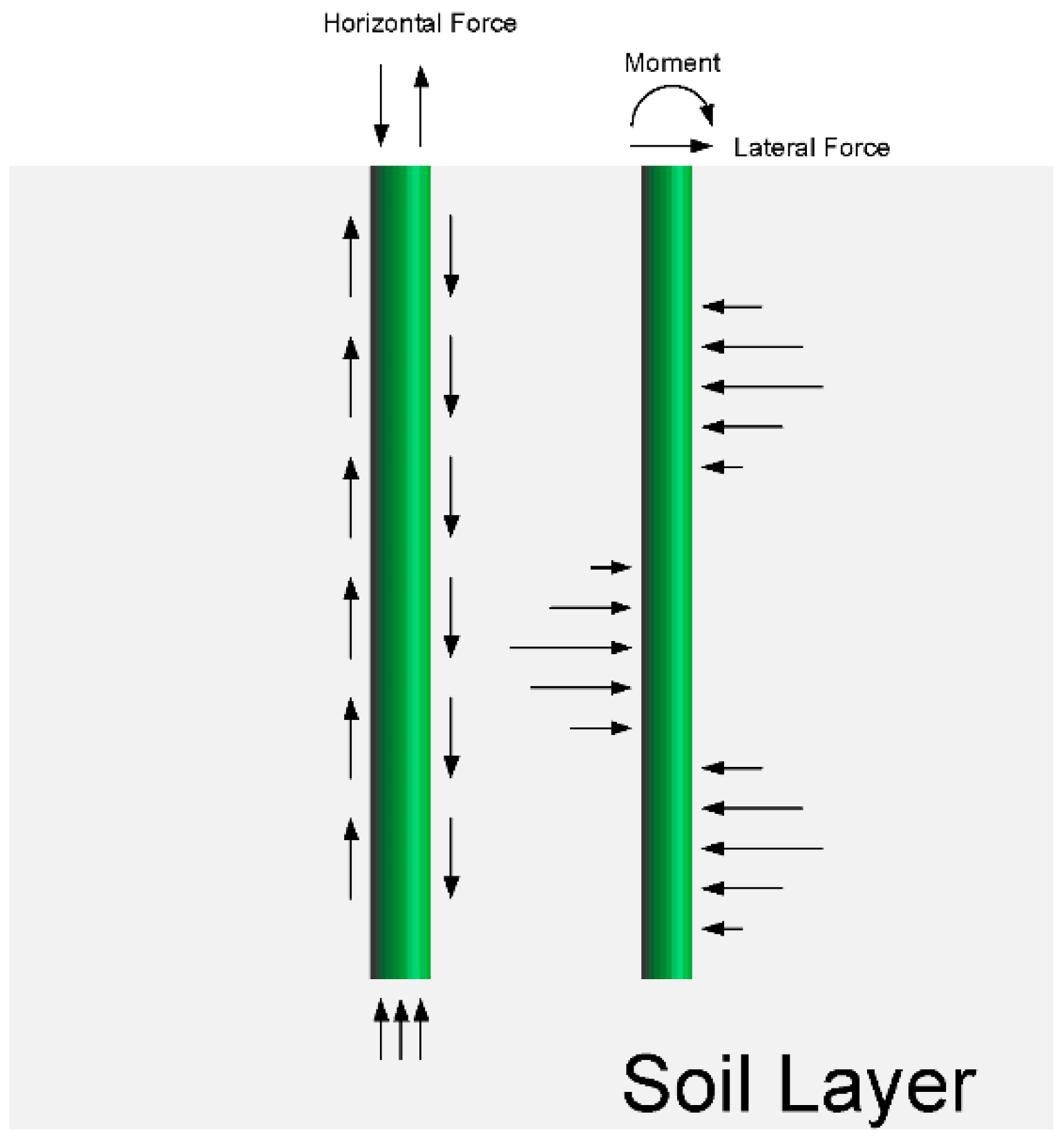
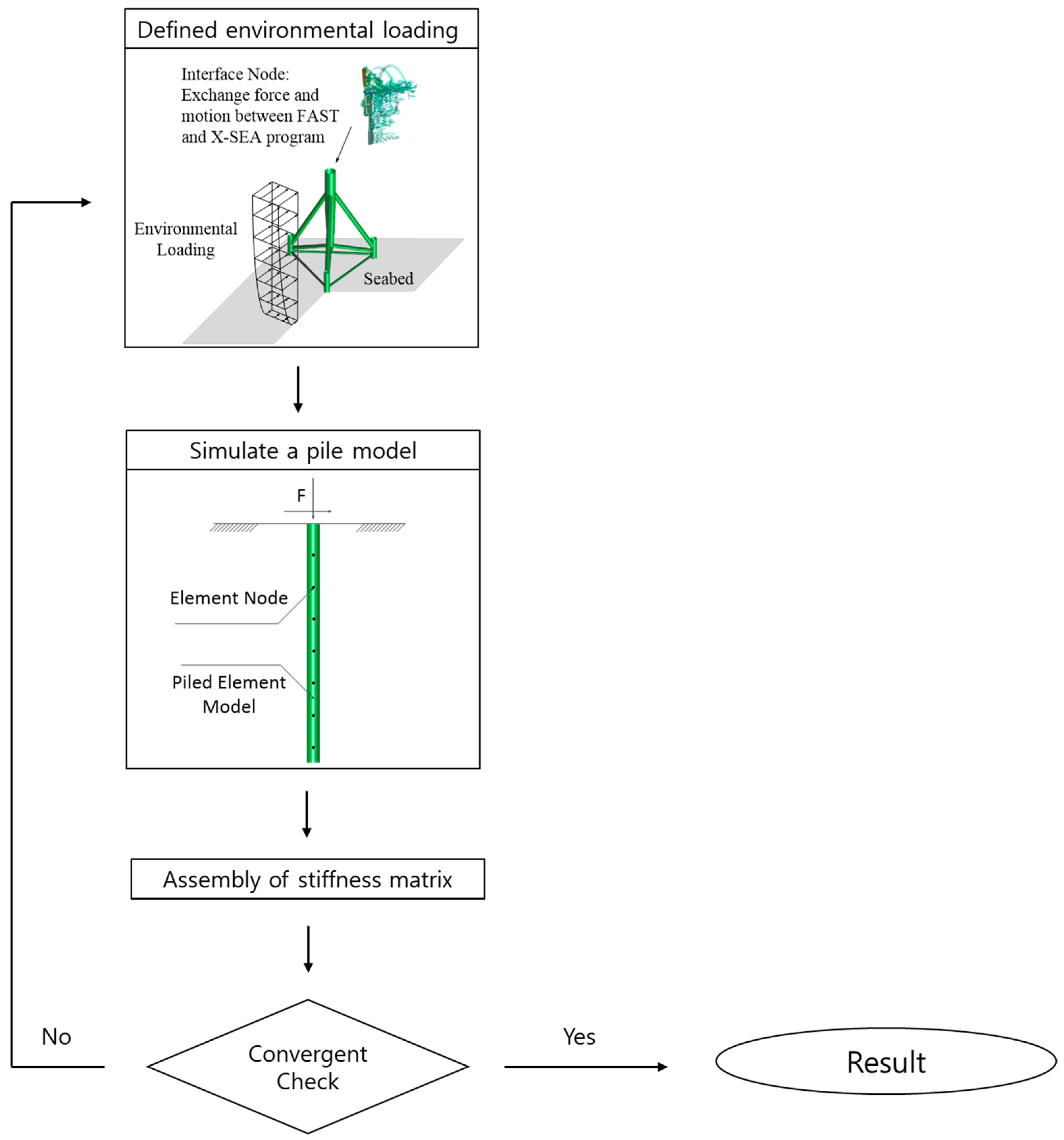
2.5. Soil-Pile-Structure Interaction Analysis

The computer simulation of a pile foundation accounts for the stiffness of the pile and the lateral and horizontal behavior of the soil. The nonlinear behavior for pile-soil interaction, as shown in Figure 5, is considered based on the geotechnical data for the lateral load deflection ( P Y ), axial load transfer and pile displacement ( T Z ), and tip-load displacement ( Q Z ) curves in order to obtain a rigorous solution to the pile-soil-structure interaction. The variation in soil stiffness should be considered [22] if the soil conditions at the supports are different from each other. In addition, the superelement concept [17] is introduced to reduce the computational time where the basic idea is to use the condensation of the stiffness matrix to reduce the number of degrees of freedom and time consumption in the finite element analysis.

2.6. A Scheme for Coupled Analysis Including the Soil-Pile-Structure Interaction

The proposed method required a four-step pre-processing procedure as shown in Figure 6. In order to define the reaction forces with turbine effects, the coupled approach described in Section 2.1, Section 2.2, Section 2.3, Section 2.4 and Section 2.5 is used. The X-SEA program was simulating substructure with a pile model as an individual pile analysis to calculate the stiffness, which considers the condensation of stiffness for pile superelement. This procedure implies that the pile-soil-structure interaction behavior has to be evaluated several times to calculate the appropriate stiffness matrix.

3. Numerical Example

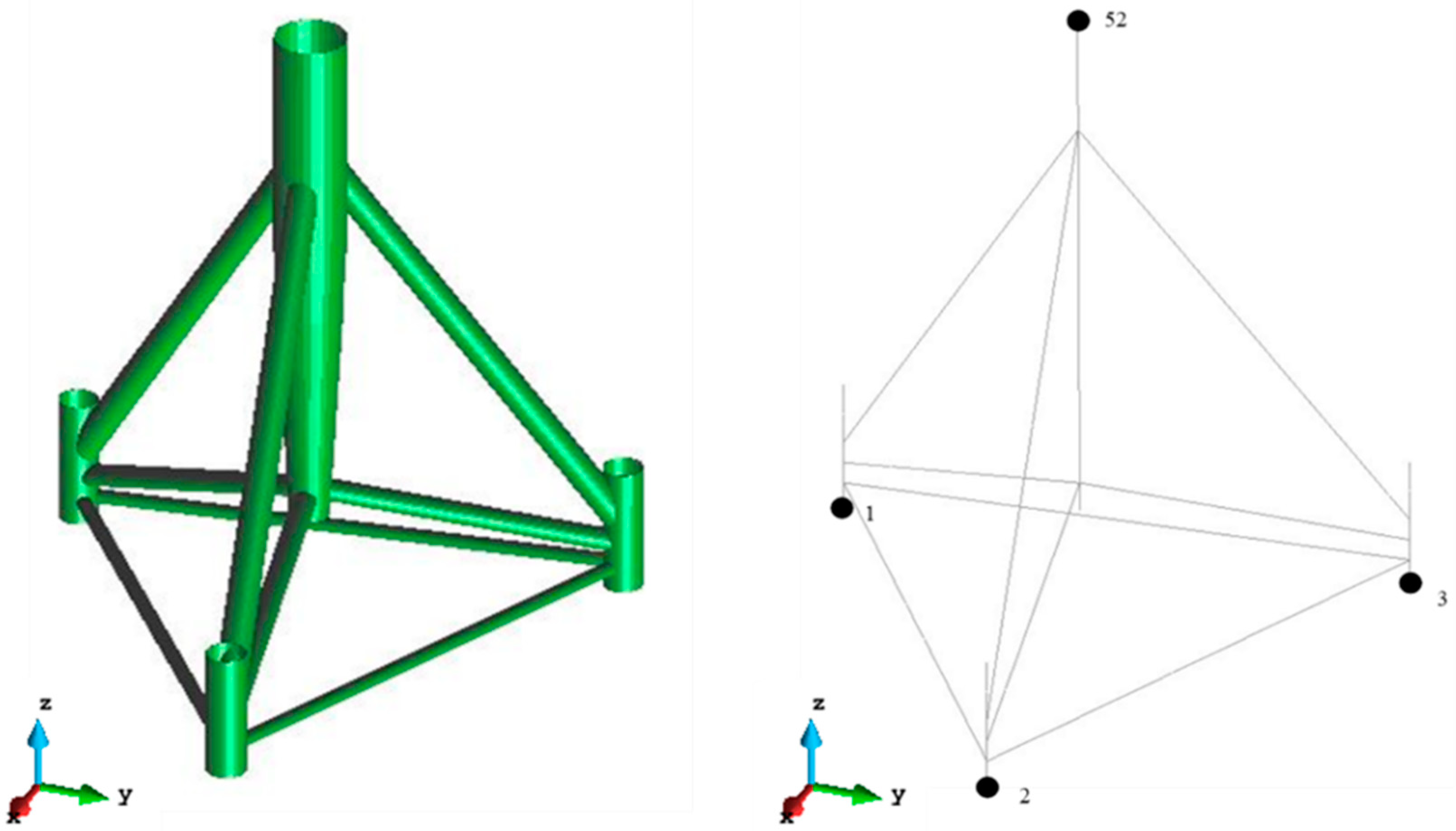
3.1. Verification of Tripod Structures Supporting NREL 5MW Offshore Wind Turbines

The tripod support structure of a wind turbine, which was researched in NREL, was sitting on the seabed with a fixed boundary condition of 55 m long driven into a 45 m water depth, and extended 10 m above the mean sea level. This structure was modelled in the X-SEA program with external forces acquired from the hydrodynamic module in the FAST program. The water density is 1027 kg/m3, the significant wave height is 8 m, the wave period is 10 s and steady wind velocity is 8 m/s at a reference height of 90 m above the mean sea level. Based on the longest natural periods, the structure and the wave period, the analysis period was selected as the first 60 s, which should correspond to the start-up to power production and consists of both transient and steady behaviour. The support structure was modeled by using 158 nodes and 163 elements as illustrated in Figure 7. The geometry and material properties of the tripod structure are given in Table 1. The verification example focused on comparing six components of dynamic reaction forces and top-tower forces that resulted from FAST and from X-SEA coupled with the FAST program, as theoretically presented in Section 2 and Figure 3 and Figure 4. The comparison was aimed at confirming that the X-SEA program could produce the same correct results as FAST.
Figure 8 and Figure 9 show that the six components of the reaction forces ( R x , R y , R z ) and moments ( R m x , R m y , R m z ) resulting from X-SEA are in good agreement with the corresponding results from FAST. These responses, except for Rx, appear to be transient and significantly attenuated in the first 30 s and then become steady. Such initial transient behaviour is due to the small amount of damping in the structure and the method by which the hydrodynamic load and aerodynamic loading are initialized at the start of the simulation. Therefore, the transient responses are quickly damped out.
The marginal differences between the X-SEA and FAST results in Figure 8 and Figure 9 can be attributed to the fact that the ratio of X-SEA/FAST obtained from the natural frequency of the six mode shapes are 0.99942, 0.99943, 0.99954, 0.99960, 0.99960 and 0.99944, respectively, as illustrated in Figure 10. The six dynamic components of the turbine load that were obtained by applying the X-SEA and FAST programs on the frame elements are identical, as shown in Figure 11 and Figure 12. It can therefore be concluded that the present study program performs normally.
In the first mode, the tripod support structure was oscillating at the local members connected to the pile head without considerable movement of the whole structure, as illustrated in Figure 13a. The second mode is the same as the first mode but the structure was oscillating in other directions and at different members, as illustrated in Figure 13b. The third to sixth modes are the in-plane and out-of-plane bending modes, which occurred at the local members, but they were oscillating in other directions as illustrated in Figure 13c–f, respectively.

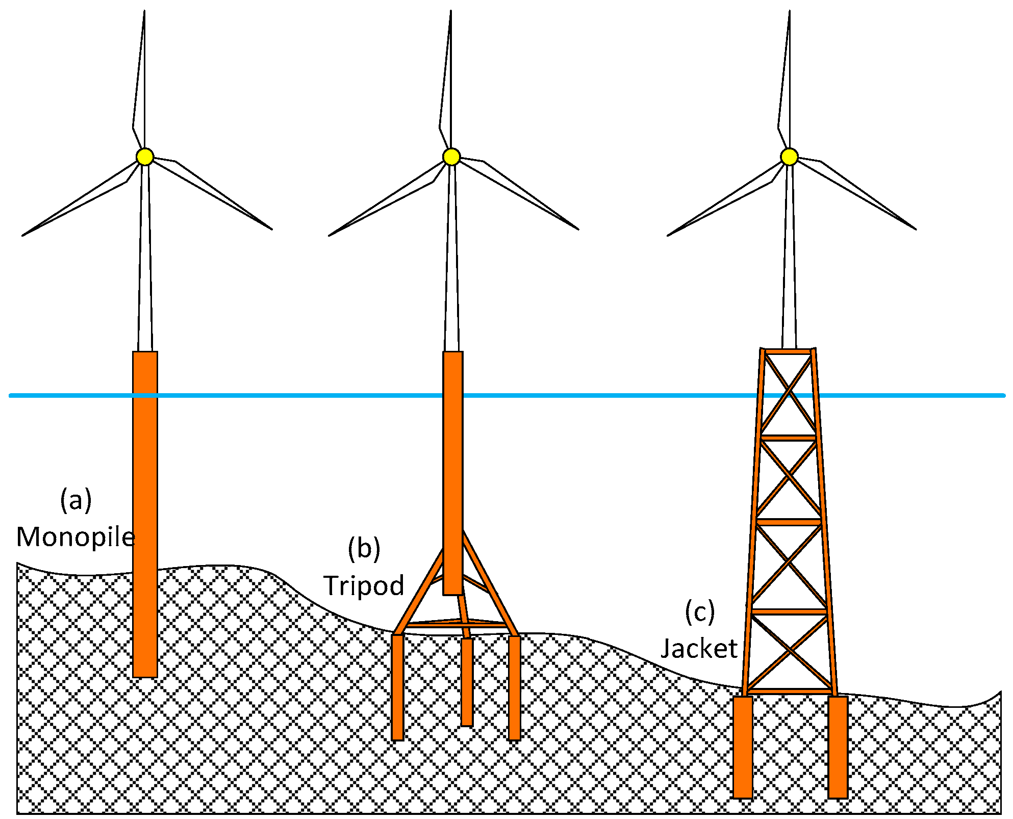
3.2. Parametric Study of Tripod/Jacket-Supported Offshore Wind Turbines

In the coupled analysis method, the motions are interchanged between the FAST and X-SEA programs, and this considers the response of the tower corresponding to the turbine response. X-SEA determines the hydrodynamic forces and computes the response of the foundation and the support structure. The values are exchanged between these two programs by using the present study module. The important components in the equations of motion including displacement, velocity and acceleration are input to X-SEA. The six force components at the integral time step are then computed in X-SEA and returned to FAST.
In this example, a 5MW OWT supported by a tripod structure that was researched by NREL was used. The model is sitting on the seabed, is 55 m high, driven through 45 m of water and extends 10 m above the mean sea level, and takes account of environmental conditions including a wave height of 2.8 m and wave period of 6.07 s. In addition, the uncoupled analysis method was developed by taking six load components at the tower base produced by FAST. Those loads can be applied at the interface node using X-SEA to compute the responses and for comparing with the coupled analysis.
The responses in the x-direction and y-direction of the tripod support structure that resulted from the coupled analysis are considerably smaller than the results of the uncoupled analysis, as plotted in Figure 14 and Figure 15. This can be attributed to the fact that in the coupled models, the interaction between the tower and support structures has been included in that results thanks to the additional coupling stiffness. This effectiveness of the coupled models in simulating more accurate responses has been observed in the dynamic analyses of jacket supported OWTs [21] and floating OWTs [29].

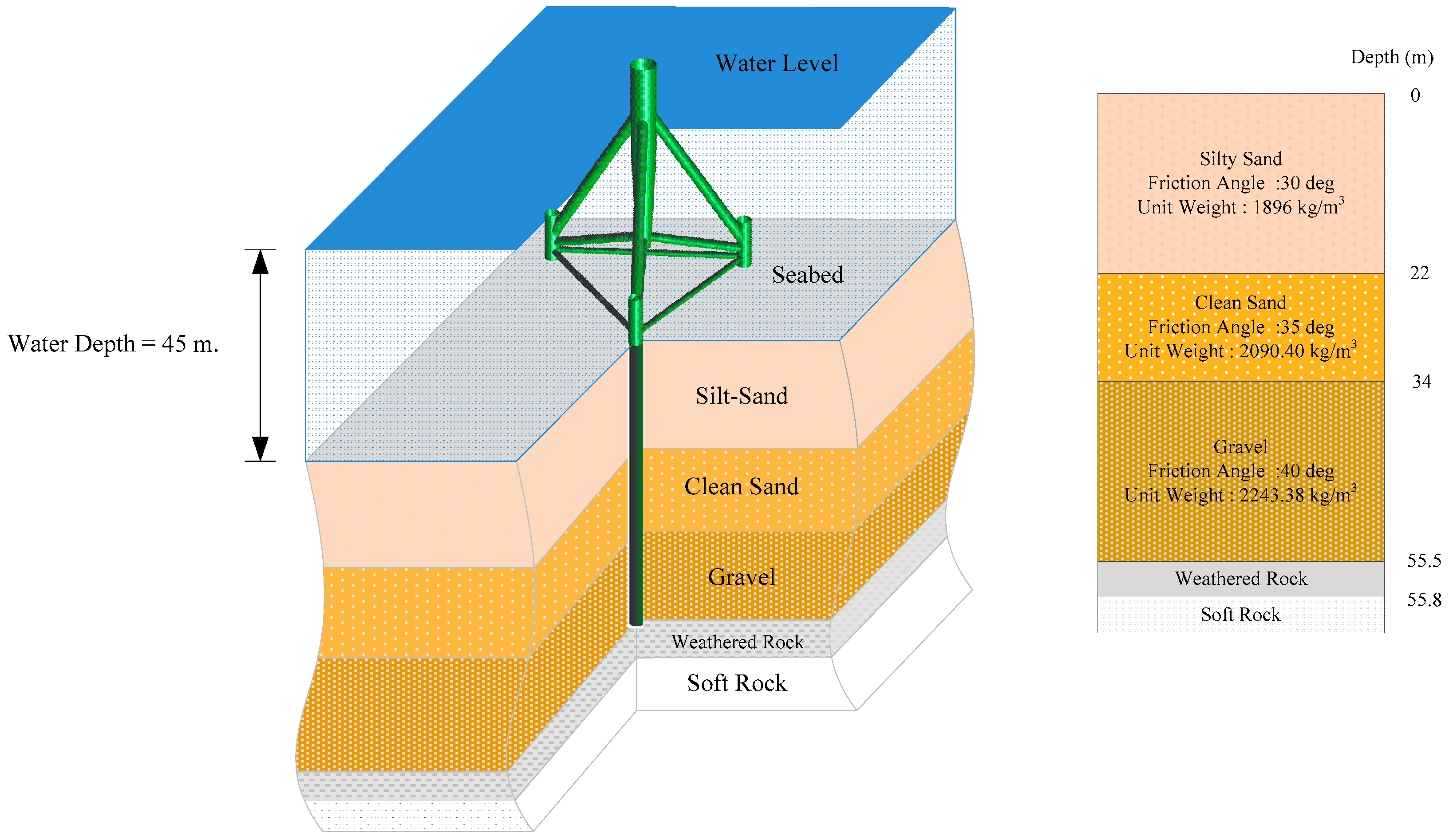
3.3. Coupled Analysis of OWT Support Structures Including the Pile-Soil-Structure Interaction

The previous section demonstrated the accuracy of the responses of fixed support structures for OWTs by using coupled models and analyses. In this section, the tripod support structure that was researched by NREL, with its geometry and properties described in Figure 7 and Table 1 is used for this parametric study. The environmental conditions are: 2.8 m wave height and 6.07 s wave period. Three models were investigated including the pile supported structure, pile superelement, and fixed support structure. The soil behavior is assumed to be nonlinear soil stiffness due to P Y , T Z , and Q Z curves in the specified offshore design standards. The pile of 1.5 m diameter and 0.05 m thickness penetrated the soil and embedded 55 m deep. The five soil layers with their soil data properties are listed in Figure 16. Another advanced technique introduced in this paper is the condensation of the stiffness matrix to reduce the degree of freedom size and computational time in the finite element analysis.
One of the primary purposes of free vibration and dynamic analysis is to avoid the cases where a non-stationary load can resonate with the structural system when the structure is excited by a loading frequency close to a natural frequency of the system. Thus, a design chart provides the first to sixth mode shapes and the corresponding natural frequencies in Figure 17 and Figure 18. A scaling factor of 25 was used to amplify the mode shapes and only the odd modes are displayed in Figure 17 and Figure 18 since the even modes have the same frequencies that vibrate in the orthogonal planes.
In the first mode shape, the piled support structure is oscillating globally in the x-direction as a bending mode of the whole structure with a natural frequency of 3.521 Hz, as illustrated in Figure 18a. The second mode has a similar shape to the first mode and a natural frequency of 3.539 Hz. It oscillates in large movements in the x-direction as shown in Figure 18b while the third mode shape with a natural frequency of 3.848 Hz is oscillating in the opposite x-direction, as illustrated in Figure 18c. The fourth mode shape has natural frequencies of 3.857 Hz and the movement of a local member. which is connected to the pile head. This mode is oscillating in the negative x-direction as shown in Figure 18d. In the fifth and sixth mode shapes, the main tubular stays still and both of the local members, which are connected to the pile head, oscillate with frequencies of 4.005 Hz and 4.047 Hz, respectively, as illustrated in Figure 18e,f.
By comparing the natural frequencies that resulted from the fixed support structure model, it is seen that the natural frequencies resulting from the piled support structure model are increased 1.148, 1.142, 1.055, 1.057, 1.017, and 1.012 times as illustrated in Figure 17. These significant differences in natural frequency relate to the self-weight or mass and stiffness of the supporting pile and soils. The piled-support models were found to represent the tripod structure more realistically and to produce more accurate natural frequencies.
The displacements in the x-direction that resulted from the fixed support structure model and the piled support structure model are plotted in Figure 19. It can be noted that the piled support structure and pile superelement model produced responses 1.399 times more flexible that those of the fixed support structure model. It is important to note in Figure 20 that the displacements in y-direction from both the piled support and superelement models have a similar trend in the x-direction but are 1.731 times larger than that of the fixed support model. It is shown that, besides the physical factors such as environmental loads, turbine operation, mechanical and material properties of structures and soils, the simulated responses of the OWT and support structure are significantly influenced by the chosen model. The inclusion of pile-soil-structure interaction and 3D nonlinear soil stiffness make the prediction of the OWT-support structure responses more accurate and closer to the real behaviour.

4. Concluding Remarks

Theoretical aspects and simulations of the coupled analysis of an offshore wind turbine (OWT) and its tripod support structure using a number of advanced techniques have been presented. The pile-soil-structure interaction was used to accurately represent the 3D nonlinear behavior of soil. The superelement of piles and condensation of the stiffness matrix was used for both computational efficiency and maintaining the numerical accuracy. By replacing the sub-structural module in FAST with the component of offshore substructures in X-SEA, the reaction forces and wind turbine loads and responses were calculated in each time step. The following conclusions are drawn from the numerical examples:
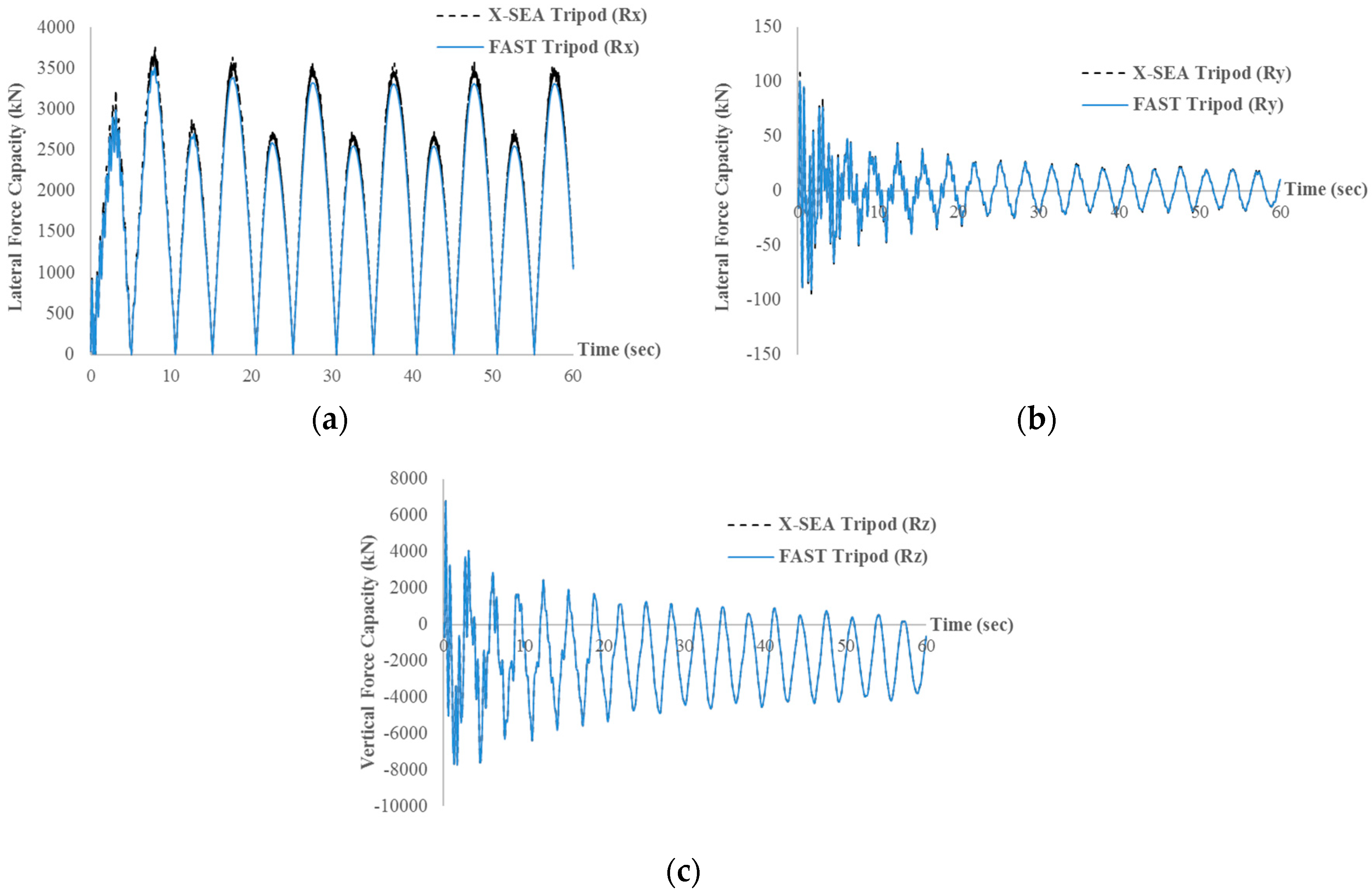
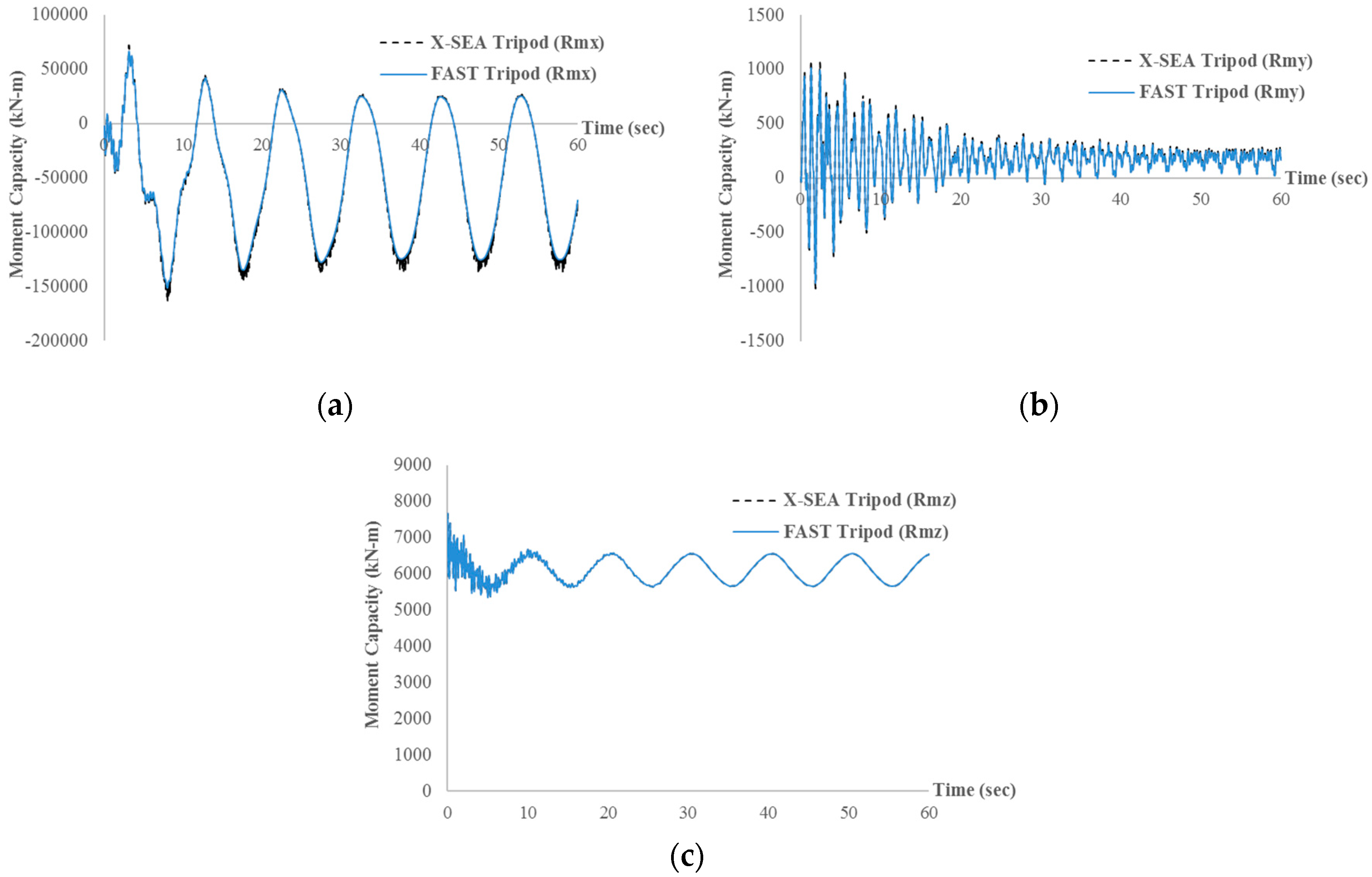
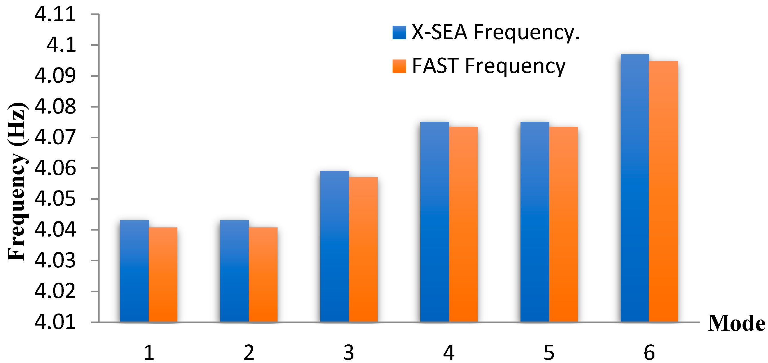
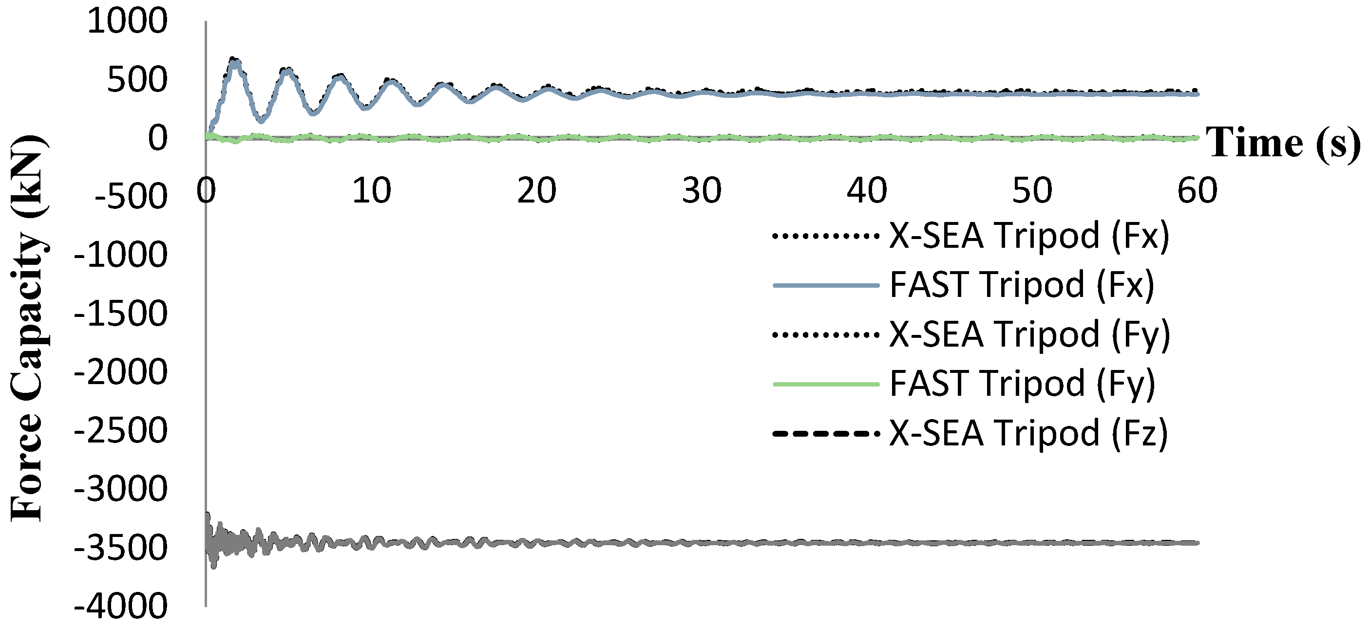
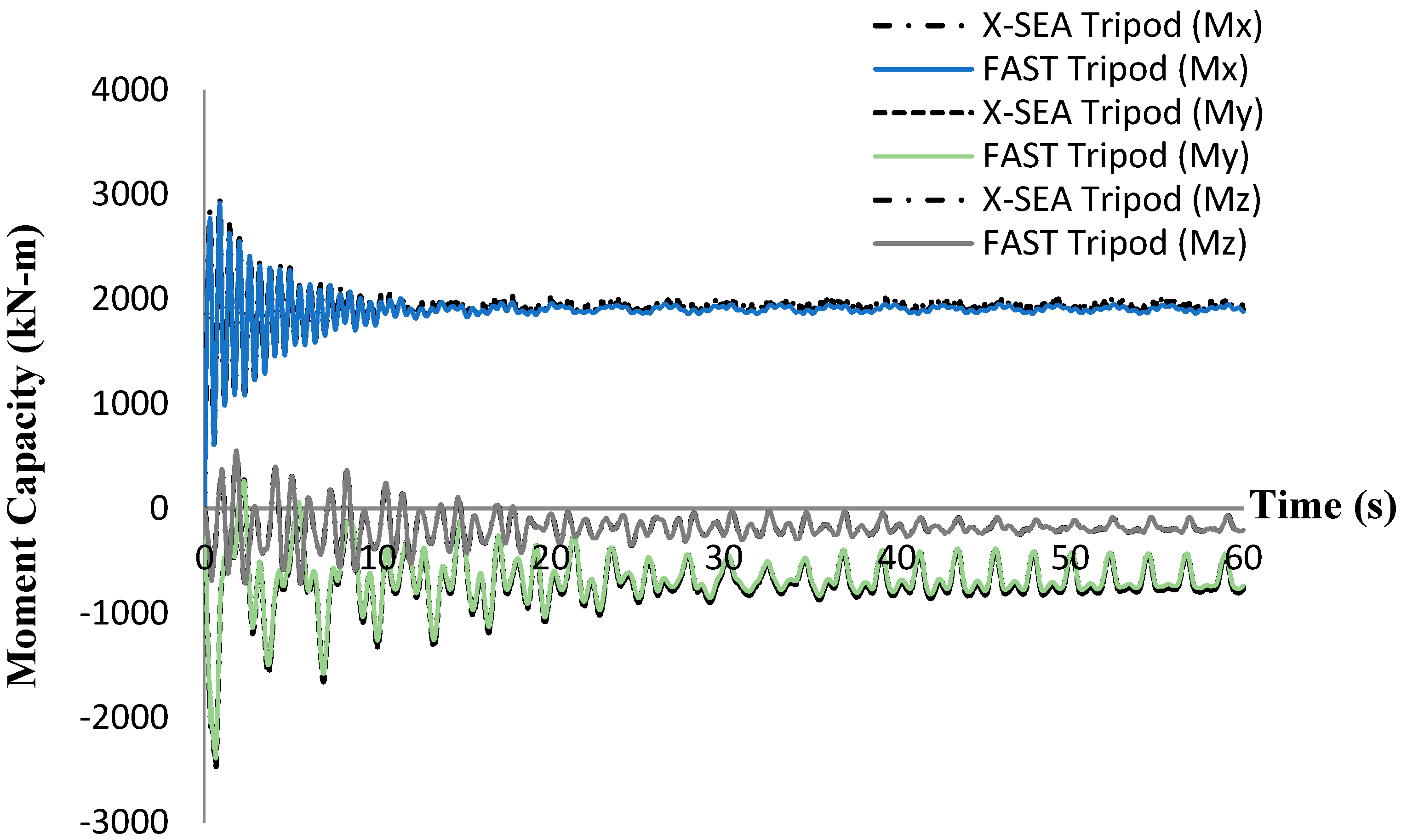
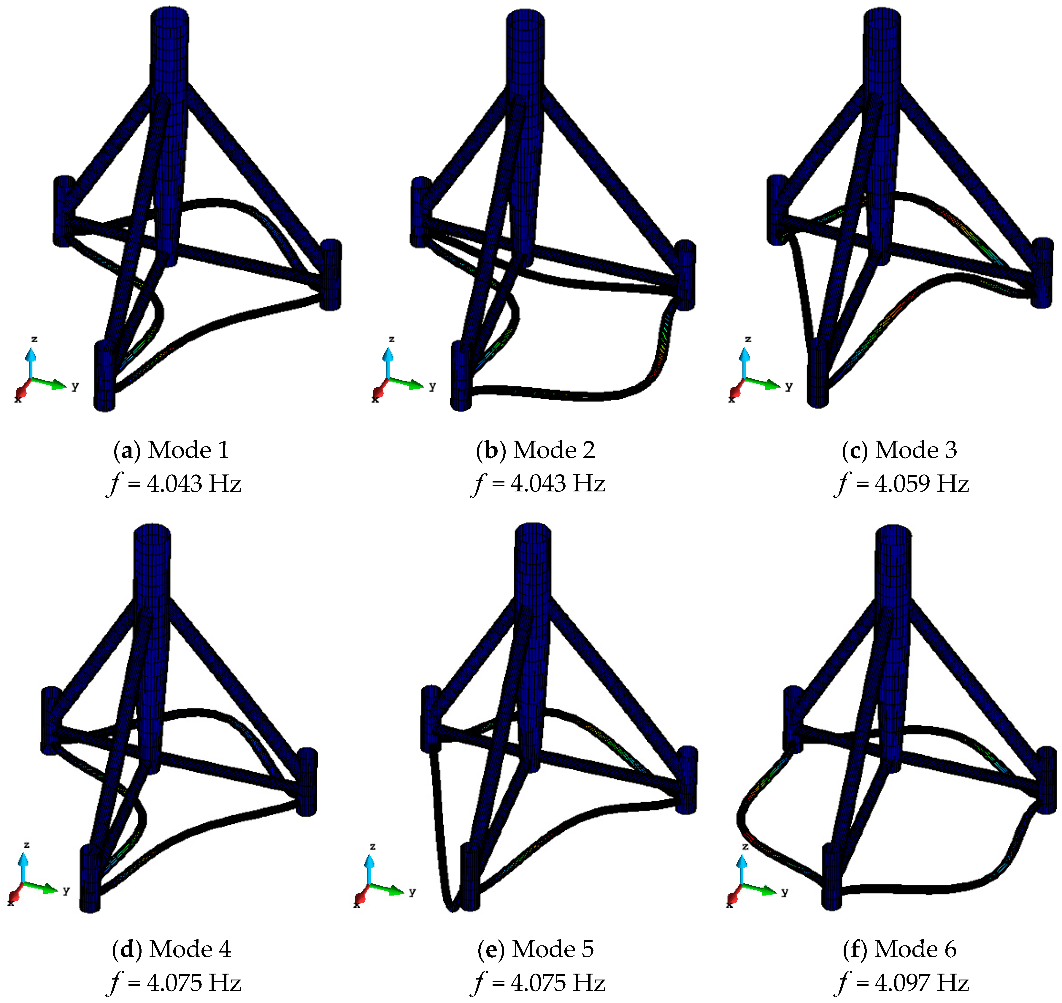
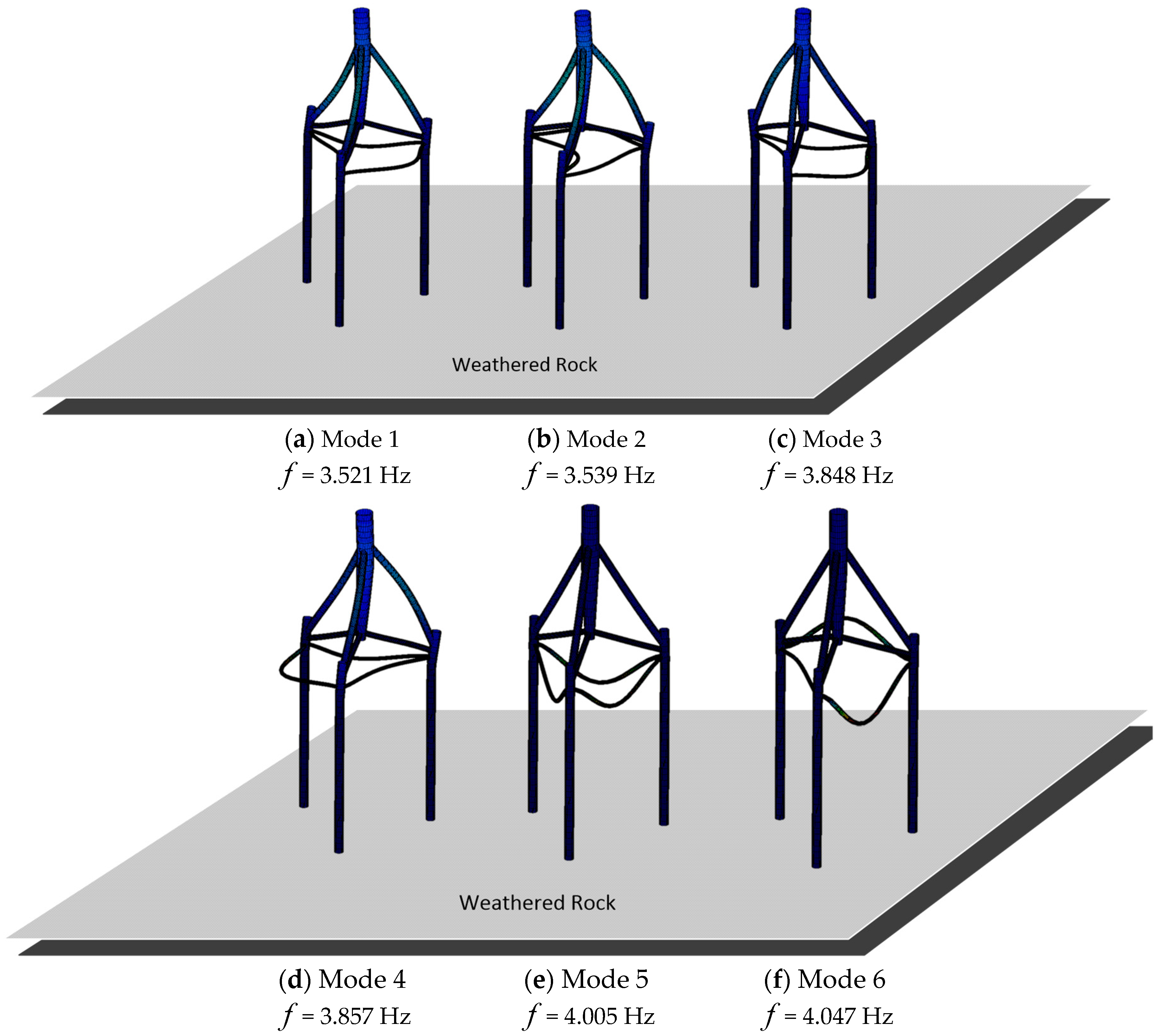
  • For the tripod structure itself, the first to sixth modes are oscillating at a local member connected to the pile head. The sixth mode is the globally bending mode. The reaction forces and moments, natural frequencies and top-tower forces that resulted from X-SEA were in good agreement with those that resulted from FAST.
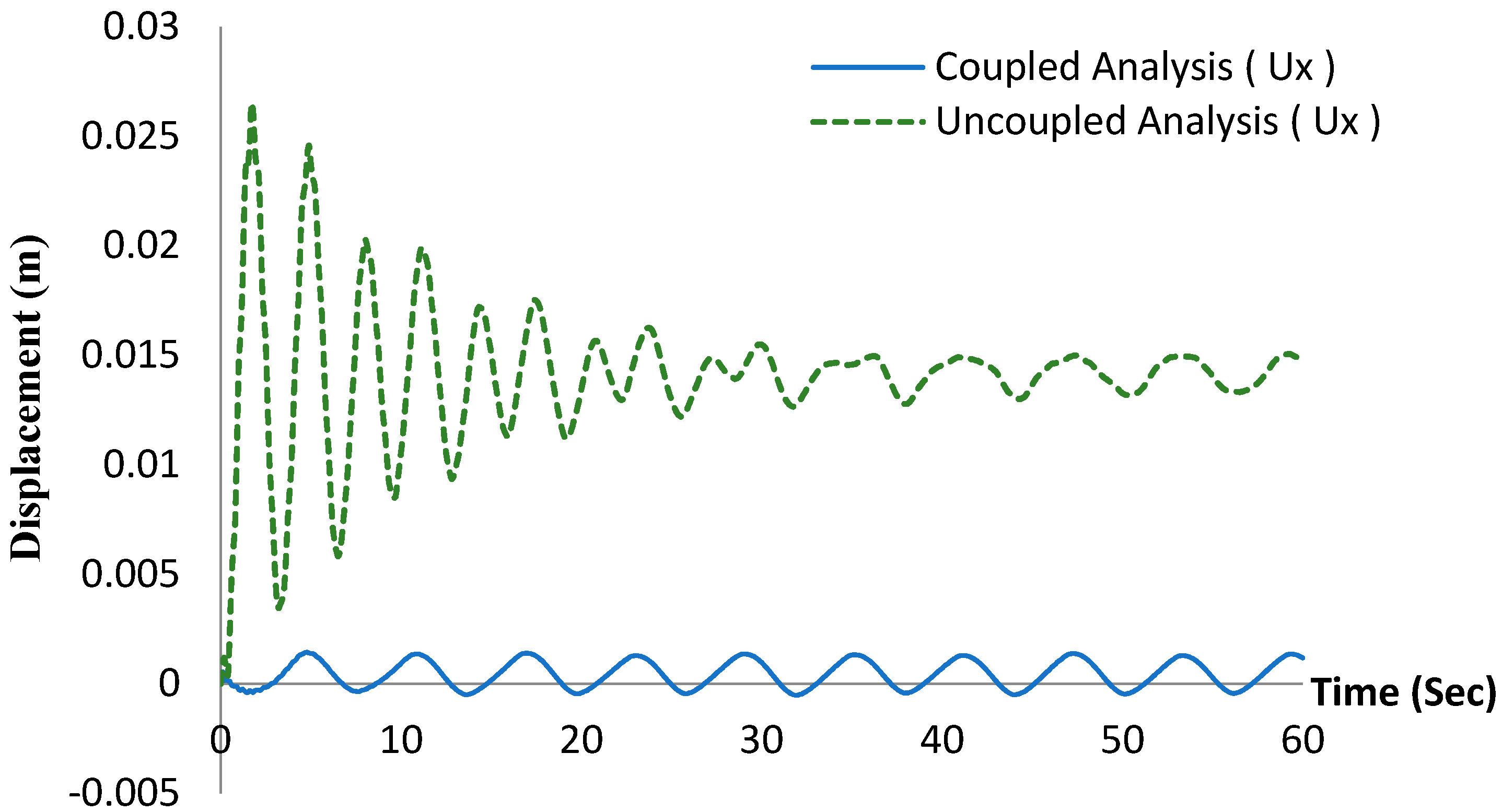
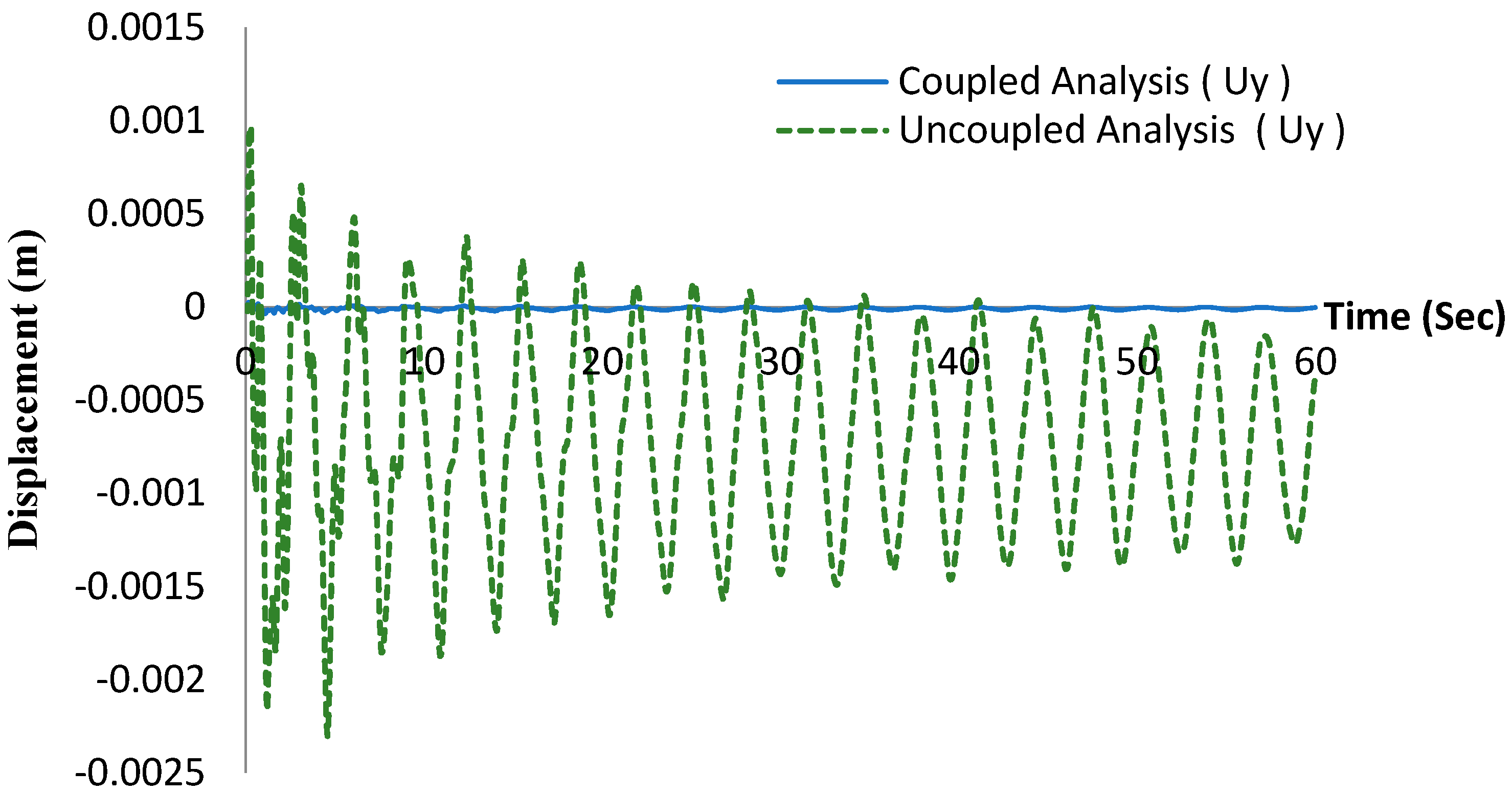
  • The physical interaction between the tower and support structure has been included in the coupled models as additional coupling stiffness, which results in considerably smaller responses compared to the uncoupled models. This demonstrates that the coupled model should be used in the analysis and design of offshore wind turbine structures.
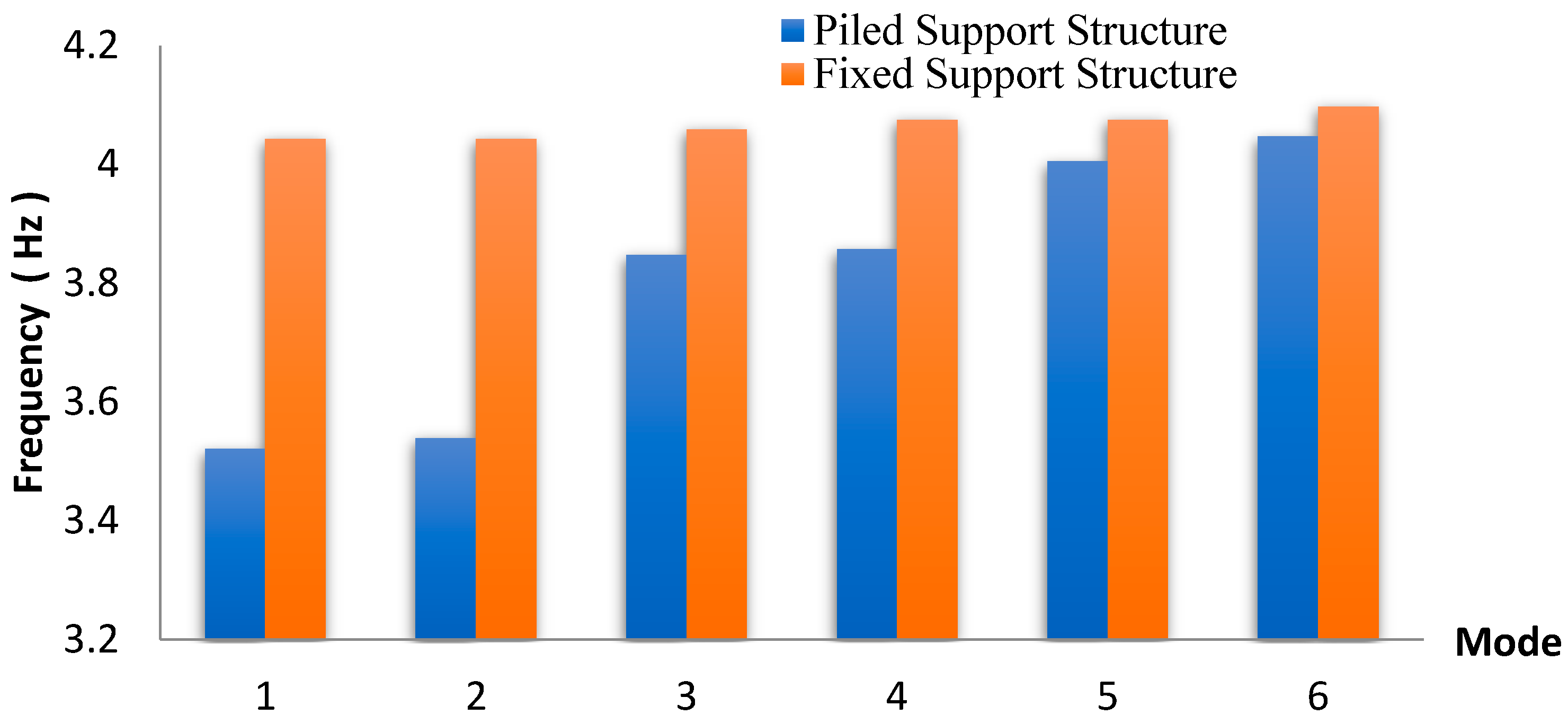
  • For the piled-support tripod structures, the first to third modes are global whereas the fourth to sixth mode shapes are at a local member connected to the pile head. Their natural frequencies are considerably larger than those of the fixed support model as the physical interactions and infinite stiffness of the supporting pile-soil have been accounted for. This demonstrates the higher accuracy and validity of the piled-support structure model.
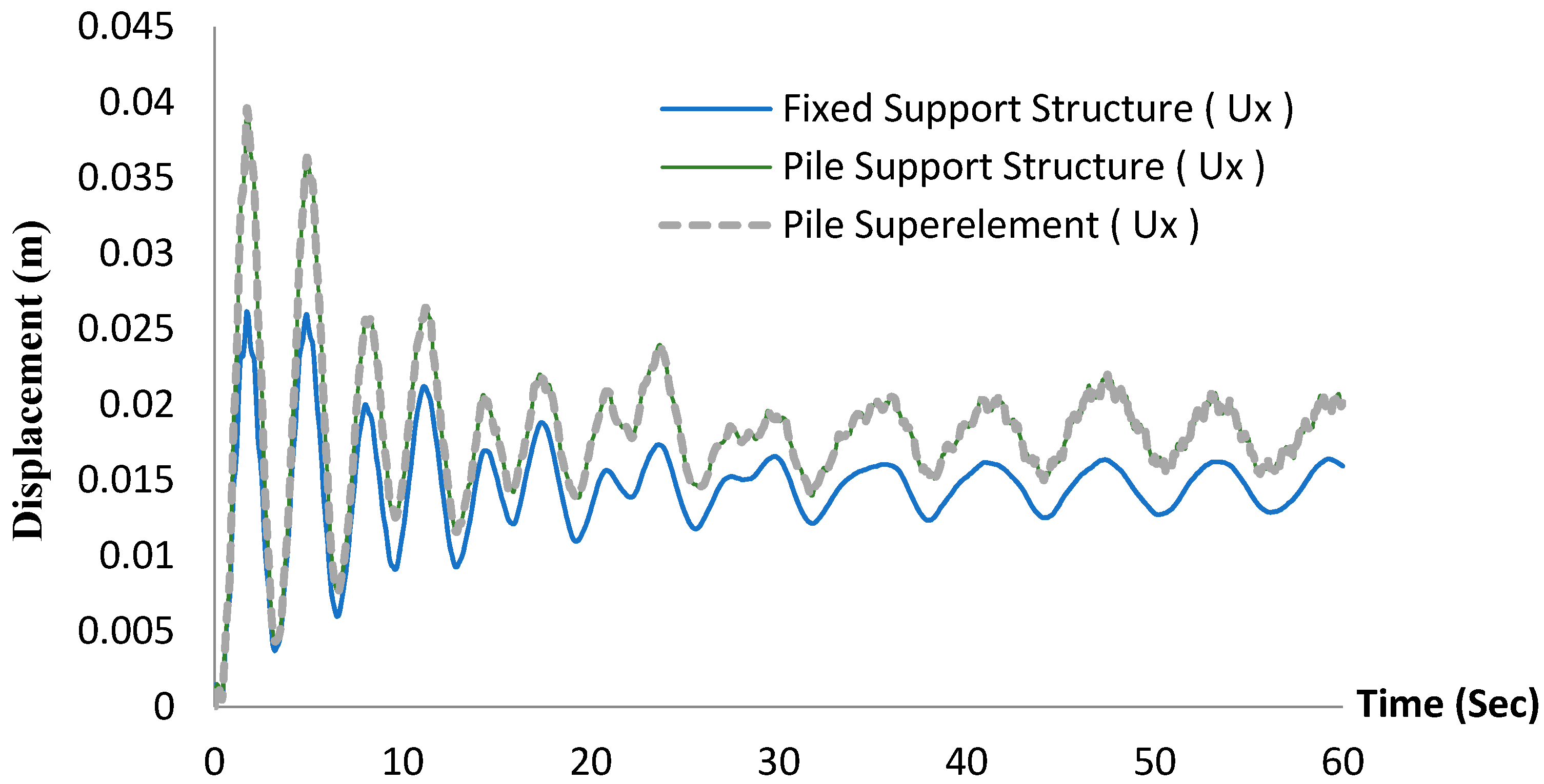
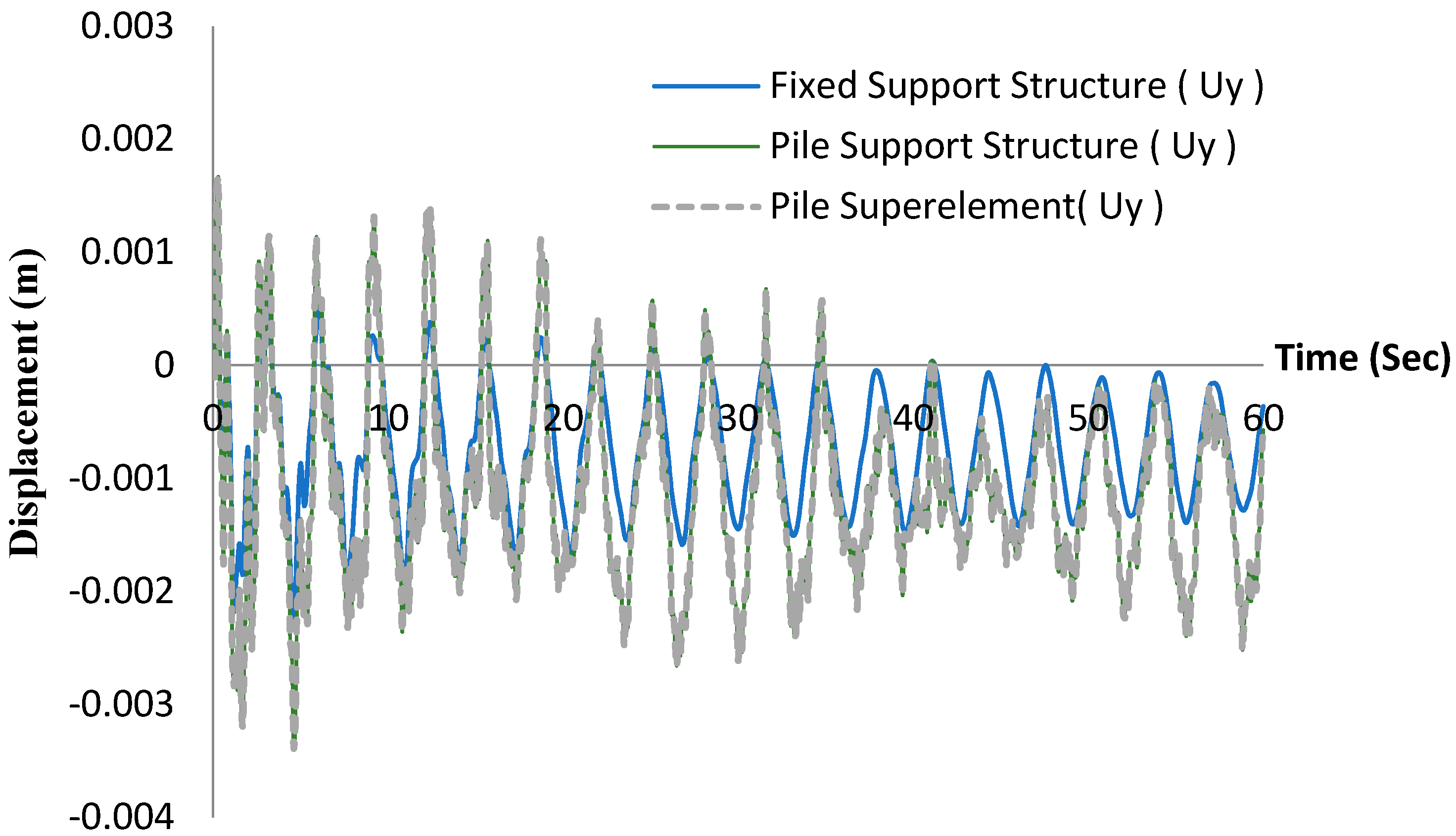
  • The piled-support model produces larger responses than the fixed support model but is identical to the pile superelement model. Besides the physical factors, the simulation of OWT structures is significantly influenced by the chosen model, because it needs condensed stiffness information for the foundation base.
For future studies, physical models or measurements from real structures are recommended. The inclusion of 3D nonlinear soil stiffness into pile-soil-structure interaction would make the simulation more accurate and realistic. Other approaches to modeling soil-structure interaction, especially the inclusion of soil damping where energy dissipates during vibration could be considered.

Author Contributions

Formal analysis, P.P.; investigation, P.P. and V.N.D.; Validation, P.P.; Conceptualization, V.N.D. and K.-D.K.; Methodology, V.N.D. and K.-D.K.; Writing—original draft preparation, P.P. and V.N.D.; Writing—review and editing, V.N.D. and K.-D.K.; Funding acquisition, K.-D.K.

Funding

This work is supported by Konkuk University, Seoul, Korea.

Conflicts of Interest

The authors declare no conflict of interest.

References

  1. Esteban, M.D.; López-Gutiérrez, J.-S.; Negro, V. Gravity-based foundations in the offshore sector. J. Mar. Sci. Eng. 2019, 7, 64. [Google Scholar] [CrossRef]
  2. Oh, K.-Y.; Nam, W.-C.; Ryu, M.-S.; Kim, J.-Y.; Epureanud, B.I. A review of foundations of offshore wind energy convertors: Current status and future perspectives. Renew. Sustain. Energy Rev. 2018, 88, 16–36. [Google Scholar] [CrossRef]
  3. Ryu, M.S.; Kim, J.-Y.; Lee, J.-S. Comparison of two meteorological tower foundations for offshore wind turbines. In Proceedings of the Twenty-Sixth International Offshore and Polar Engineering Conference, Rhodes, Greece, 26 June–2 July 2016. [Google Scholar]
  4. Kim, S.-R.; Hung, L.C.; Oh, M. Group effect on bearing capacities of tripod bucket foundations in undrained clay. Ocean Eng. 2014, 79, 1–9. [Google Scholar] [CrossRef]
  5. Schaumann, P.; Böker, C. Can jackets and tripods compete with monopiles? In Proceedings of the Copenhagen Offshore Wind, Copenhagen, Denmark, 6–28 October 2005. [Google Scholar]
  6. Zaaijer, M.B. Comparison of Monopile, Tripod, Suction Bucket and Gravity Base Design for a 6 MW Turbine; Delft University of Technology: Delft, The Netherlands, 2003. [Google Scholar]
  7. Ryu, M.S.; Kim, J.-Y.; Kang, K.-S. The first met-mast for offshore wind farm in Korea and its remote sensing system. In Proceedings of the Twenty-First International Offshore and Polar Engineering Conference, Maui, HI, USA, 19–24 June 2011. [Google Scholar]
  8. Chen, D.; Huang, K.; Bretel, V.; Hou, L. Comparison of structural properties between monopile and tripod offshore wind-turbine support structures. Adv. Mech. Eng. 2013, 5, 1–9. [Google Scholar] [CrossRef]
  9. Hung, L.C.; Kim, S.-R. Evaluation of combined horizontal-moment bearing capacities of tripod bucket foundations in undrained clay. Ocean Eng. 2014, 85, 100–109. [Google Scholar] [CrossRef]
  10. Tran, N.X.; Hung, L.C.; Kim, S.-R. Evaluation of horizontal and moment bearing capacities of tripod bucket foundations in sand. Ocean Eng. 2017, 140, 209–221. [Google Scholar] [CrossRef]
  11. Yang, H.; Zhu, Y.; Lu, Q.; Zhang, J. Dynamic reliability based design optimization of the tripod sub-structure of offshore wind turbines. Renew. Energy 2015, 78, 16–25. [Google Scholar] [CrossRef]
  12. Margariti, G.; Papadopoulos, A.; Barmpas, D.; Gantes, C.J.; Gkologiannis, C.P. Design of monopile and tripod foundation of fixed offshore wind turbines via advanced numerical analysis. In Proceedings of the 8th GRACM International Congress on Computational Mechanics, Volos, Greece, 2–15 July 2015. [Google Scholar]
  13. Hübler, C.; Hafele, J.; Gebhardt, C.G.; Rolfes, R. Experimentally supported consideration of operating point dependent soil properties in coupled dynamics of offshore wind turbines. Mar. Struct. 2018, 57, 18–37. [Google Scholar] [CrossRef]
  14. Häfele, J.; Hübler, C.; Gebhardt, C.G.; Rolfes, R. An improved two-step soil-structure interaction modeling method for dynamical analyses of offshore wind turbines. Appl. Ocean Res. 2016, 55, 141–150. [Google Scholar] [CrossRef]
  15. Dinh, V.N.; McKeogh, E. Offshore Wind Energy: Technology Opportunities and Challenges. In Lecture Notes in Civil Engineering, Proceedings of the Vietnam Symposium on Advances in Offshore Engineering, Hanoi, Vietnam, 25 September 2018; Springer: Singapore, 2018. [Google Scholar] [CrossRef]
  16. Ong, M.C.; Bachynski, E.E.; Økland, O.D.; Passano, E. Dynamic responses of a jacket-type offshore wind turbine using decoupled and coupled models. In Proceedings of the ASME 2014 33rd International Conference on Ocean, Offshore and Arctic Engineering (OMAE), San Francisco, CA, USA, 8–13 June 2014. [Google Scholar]
  17. Voormeeren, S.N.; van der Valk, P.L.C.; Nortier, B.P.; Molenaar, D.-P.; Rixen, D.J. Accurate and efficient modeling of complex offshore wind turbine support structures using augmented superelements. Wind Energy 2014, 17, 1035–1054. [Google Scholar] [CrossRef]
  18. Kim, K.D.; Plodpradit, P.; Manovachirasan, A.; Sinsabvarodom, C.; Kim, B.J. Analysis of offshore structures for wind turbines and oil and gas using X-SEA software. In Proceedings of the 11th World Congress on Computational Mechanics (WCCM XI), 5th European Conference on Computational Mechanics (ECCM V), 6th European Conference on Computational Fluid Dynamics (ECFD VI), Barcelona, Spain, 20–25 July 2014. [Google Scholar]
  19. Kim, K.-D.; Vachirapanyaku, S.; Plodpradit, P.; Dinh, V.-N.; Park, J.-H. Development of offshore structural analysis software X-SEA coupled with FAST. In Proceedings of the 38th International Conference on Ocean, Offshore & Artic Engineering, ASME 2019 OMAE 2019-96778, Glasgow, Scotland, UK, 9–14 June 2019. [Google Scholar]
  20. Jonkman, J. FAST v8. National Renewable Energy Laboratory (NREL). USA, 2018. Available online: https://nwtc.nrel.gov/FAST8 (accessed on 19 September 2017).
  21. Plodpradit, P.; Dinh, V.-N.; Kim, K.-D. Coupled analysis of offshore wind turbine jacket structures with pile-soil-structure interaction using FAST v8 and X-SEA. Appl. Sci. 2019, 9, 1633. [Google Scholar] [CrossRef]
  22. Dinh, V.N.; Basu, B.; Brinkgreve, R.B.J. Wavelet-based evolutionary response of multi-span structures including wave-passage and site-response effects. J. Eng. Mech. 2014, 140, 8. [Google Scholar] [CrossRef]
  23. Failla, G.; Santangelo, F.; Foti, G.; Scali, F.; Arena, F. Response-spectrum uncoupled analyses for seismic assessment of offshore wind turbines. J. Mar. Sci. Eng. 2018, 6, 85. [Google Scholar] [CrossRef]
  24. Basu, B.; Staino, A.; Dinh, V.N. Vibration of wind turbines under seismic excitations. In Proceedings of the 5th Asian-Pacific Symposium on Structural Reliability and its Applications, Singapore, 23–25 May 2012. [Google Scholar] [CrossRef]
  25. Fitzgerald, B.; Basu, B. A monitoring system for wind turbines subjected to combined seismic and turbulent aerodynamic loads. Struct. Monit. Maint. 2017, 4, 175–194. [Google Scholar] [CrossRef]
  26. Kim, K.-D. X-SEA User Manual; Konkuk University: Seoul, Korea, 2016. [Google Scholar]
  27. Kim, K.D.; Suthasupradit, S.; Kim, Y.H.; Lomboy, G.R.; Dinh, V.N. New development of XFINAS software for nonlinear dynamic and seismic analysis of structure. In Proceedings of the Third Asian-Pacific Congress on Computational Mechanics (APCOM’07) & the Eleventh International Conference on the Enhancement and Promotion of Computational Methods in Engineering and Science (EPMESC XI), Kyoto, Japan, 3–6 December 2007. [Google Scholar]
  28. Kim, B.J.; Plodpradit, P.; Kim, K.D.; Kim, H.G. Three-dimensional analysis of prestressed concrete offshore wind turbine structure under environmental and 5-MW turbine loads. J. Mar. Sci. Appl. 2018, 17, 625–637. [Google Scholar] [CrossRef]
  29. Dinh, V.N.; Basu, B.; Nielsen, S.R.K. Impact of spar-nacelle-blade coupling on the edgewise response of floating offshore wind turbines. Coupled Syst. Mech. 2013, 2. [Google Scholar] [CrossRef]
  30. Damiani, R.; Jonkman, J.; Hayman, G. SubDyn User’s Guide and Theory Manual; National Renewable Energy Laboratory (NREL): Golden, CO, USA, March 2015. [Google Scholar]
Figure 1. Common types of support structures for offshore wind turbines.
Jmse 07 00181 g001
Figure 2. The concept of the interchange substructure module of the FAST V.8 program.
Jmse 07 00181 g002
Figure 3. The concepts of uncoupled and coupled analysis.
Jmse 07 00181 g003
Figure 4. Basic layout of structure module within X-SEA.
Jmse 07 00181 g004
Figure 5. Definition of pile-soil interaction.
Jmse 07 00181 g005
Figure 6. Scheme for coupled analysis of turbine effects including pile-soil-structure interactions.
Jmse 07 00181 g006
Figure 7. Model of the NREL 5MW tripod support structure.
Jmse 07 00181 g007
Figure 8. A comparison of the dynamic lateral reaction forces in tripod support structure that resulted from X-SEA and FAST programs in the x-direction (a), y-direction (b), and z-direction (c).
Jmse 07 00181 g008
Figure 9. A comparison of the dynamic reaction moments of the tripod support structure that resulted from X-SEA and FAST programs in the x-direction (a), y-direction (b), and z-direction (c).
Jmse 07 00181 g009
Figure 10. A comparison of natural frequency values of the tripod support structure resulting from the X-SEA and FAST programs.
Jmse 07 00181 g010
Figure 11. Comparison of the dynamic top-tower forces in x, y, and z directions of the tripod support structure that resulted from the X-SEA and FAST programs.
Jmse 07 00181 g011
Figure 12. Comparison of the dynamic top-tower moments about the x, y, and z directions of the tripod support structure between the X-SEA and FAST programs.
Jmse 07 00181 g012
Figure 13. Natural frequencies and mode shapes of the tripod support structure.
Jmse 07 00181 g013
Figure 14. Comparison of deflections in the x- direction resulting from couple and uncouple analyses.
Jmse 07 00181 g014
Figure 15. Comparison of displacements in the y-direction resulting from coupled and uncoupled analyses.
Jmse 07 00181 g015
Figure 16. The tripod support structure for pile-soil-structure interaction (PSSI) modeling.
Jmse 07 00181 g016
Figure 17. The comparison of natural frequencies that resulted from the piled support structure model and the fixed support structure model.
Jmse 07 00181 g017
Figure 18. Natural frequencies and mode shapes resulting from the piled-supported structure model.
Jmse 07 00181 g018
Figure 19. A comparison of the displacements in x-direction of the fixed support structure model, piled support structure model and piled superelement model.
Jmse 07 00181 g019
Figure 20. A comparison of the displacements in y-direction of the fixed support structure model, piled support structure model, and piled superelement model.
Jmse 07 00181 g020
Table 1. Geometry and material properties of the tripod support structure.
Outer diameter of diagonal brace (m)2.475–1.200
Wall thickness of diagonal brace (m)0.035–0.025
Outer diameter of main tubular (m)5.412–1.875
Wall thickness of main tubular (m)0.05–0.035
Young’s Modulus (N/m2)2.1 × 1011
Density (kg/m3)7850

