Article

Frequency Domain Response of Jacket Platforms under Random Wave Loads

1
National Center for International Research of Subsea Engineering Technology and Equipment, Marine Engineering College, Dalian Maritime University, Dalian 116026, China
2
State Key Laboratory of Coastal and Offshore Engineering, Dalian University of Technology, Dalian 116024, China
3
State Key Laboratory of Structural Analysis for Industrial Equipment, School of Naval Architecture Engineering, Dalian University of Technology, Dalian 116024, China
*
Author to whom correspondence should be addressed.
J. Mar. Sci. Eng. 2019, 7(10), 328; https://doi.org/10.3390/jmse7100328
Submission received: 19 August 2019 / Revised: 14 September 2019 / Accepted: 17 September 2019 / Published: 21 September 2019
(This article belongs to the Special Issue Dynamics of Offshore Structures)

Abstract

:
This article presents a procedure that simplifies an offshore jacket platform as a non-uniform cantilever beam subjected to an axial force. A Ritz method combined with a pseudo-excitation method is then used to analyze the responses of the jacket platform under random wave loads with the associated power spectral densities, variances and higher spectral moments. The theoretical basis and pertinent governing equations are derived. The proposed procedure not only eases the process of determining the pseudo wave loads, but also requires only the rudimentary structural details that are typically available at the preliminary design stage. Additionally, the merit of the proposed procedure is that the process does not require one to compute the normal modes, which saves time and is particularly convenient for the dynamic-response analysis of a complex structure (such as an offshore platform). An illustrative example based on a three-deck jacket platform is presented to demonstrate the procedure used to obtain the power spectral densities, variances and second spectral moments of jacket-top displacement and the bending moment of the jacket at the mud line. The results obtained are compared with those obtained using a Finite Element Mothed (FEM) model. Based on the findings of the study and good agreement shown in the comparison of results, it is concluded that the proposed method is effective, simple and convenient, and can be a useful tool for the preliminary design analysis of offshore platforms.

1. Introduction

Fixed offshore platforms are generally used for oil development as well as to accommodate other functional uses such as equipment installation, construction operation, material and supply storage, and living quarters. Offshore jacket platforms, which may be exposed to severe environmental conditions, are generally subjected to two main categories of environmental loads: normal loads such as wave-induced hydrodynamic forces, and extreme-condition loads due to seismic excitation. The former is a well-established design consideration, and the normal loads in an ocean environment are adopted as basic parameters for structural design. The extreme sea-states are used to establish the loadings, and are well defined by design rules and advisories according to many class societies. In all concerned environmental loads, wave is a predominant one, and the response under random wave loads has been the focus of many investigations.
Sunder and Connor [1] performed a study on jacket platforms by considering the variations in wave height, uncertainties in wave period (associated with wave height), choice of hydrodynamic force coefficients (particularly in the presence of marine growth), and changes in deck mass and hysteretic structural damping. Numerical studies were performed on an equivalent simplified stick model by applying Morrison’s equation only on vertical members. Gudmestad and Moe [2] recommended a unified approach for the selection of appropriate values for the coefficients used in the calculation of the hydrodynamic loads, determined by comparing the API(American Petroleum Institute)'s and North Sea Design Practice methods and performing full-scale experiments to validate those values. Karunakaran et al. [3] used modal analysis to calculate the natural frequencies and mode shapes. Nonlinear time domain simulations were used to calculate the dynamic responses of a jacket platform, and the calculated results were compared with full-scale measurements. Considering tubular members, Horr and Safi [4] calculated the natural frequencies and mode shapes of offshore structures in a time domain using modal analysis. They used exact Timoshenko pipe elements to determine the dynamic responses of an offshore platform in a frequency domain. The response of a fixed offshore platform supported by cluster piles was investigated by Mostafa and El Naggar [5] using the Finite Element Method. They also analyzed the effects of pile–soil interaction on the dynamic characteristics of a jacket structure supported by cluster piles. They concluded that soil characteristics significantly affect the dynamic behavior of the structure. Patil and Jangid [6] compared the efficiency of viscoelastic, viscous and friction dampers as energy-dissipating devices to moderate the dynamic response of steel jacket platforms under sea wave excitations. Elshafey et al. [7] both theoretically and experimentally investigated the dynamic response of a scale model of an offshore jacket structure subjected to random wave loads. The experiments were conducted both in air and in a towing tank, and excellent agreement was obtained between the experimental and theoretical results.
Golafshani and Gholizad [8] used the stochastic linearization technique to investigate the performance of nonlinear friction dampers on reducing the wave-induced random vibrations in jacket-type offshore platforms. Later, Golafshani et al. [9] studied oil/gas jacket platforms under wave loads and found that, for two different example platforms, the difference of the maximum structural base shear under dynamic and static analyses was respectively either negligible (less than 0.5%) or approximately 14%. The dynamic analysis demonstrated a larger maximum response. The response of offshore platforms with hydrodynamic buoyant mass dampers to wave loads, which leverage on the buoyancy and inertia of the dampers for the hydrodynamic damping effects that reduce the displacement response of the platform, was investigated by Moharrami and Tootkaboni [10]. Mao et al. [11] studied the dynamic responses of offshore jacket platforms, including foundation degradation under cyclic loadings where finite element models using the lumped parameter method were established to handle pile–soil interaction. Abhinav and Saha [12] performed coupled hydrodynamic and geotechnical analyses of an offshore jacket wind turbine by considering it both with and without soil–structure interaction. A jacket in a water depth of 70 m with soil conditions off the west coast of India was used in the study. Wei et al. [13] investigated the effects of structural dynamics on the response of an offshore wind turbine supported by a jacket and subjected to wave loads. Their studies included a series of time-domain dynamic analyses based on loadings from either regular or irregular wave histories of three offshore wind-turbine-supported structures.
The literature review reveals that many researchers have focused on analyzing the dynamic responses of offshore structures subjected to wave loads. The growth of computer processing power has led an improved assessment of dynamic response performance using three-dimensional models. However, industry practitioners may be interested in other simplified but accurate dynamic analysis methods to produce results that are in good agreement with the real responses of structures, while at the same time to achieving significant time-saving in computational efforts. This is especially so in the preliminary design stage, when the information and materials of a platform are insufficient for setting up a detailed three-dimensional model. Moreover, incomplete data of a jacket structure may result in high uncertainty about its structural responses and performance under harsh environmental loads. Thus, it is necessary to develop a procedure that requires less computing time but produces high-accuracy estimations of the responses of offshore structures. A simplified approach for modelling jacket offshore platforms using the Euler beam theory was developed by Bo Zhou et al. [14]. Numerous examples have been presented to demonstrate the validity of their proposed method. Asgarian et al. [15] developed a lumped mass model to simplify the calculation of the responses of offshore jacket structures. Recently, Timoshenko’s beam theory was again applied by Bo Zhou et al. [16] to model the dynamic responses of offshore jacket platforms, where the equation of bending motion was proposed and solved. Their results of random seismic responses were compared with those obtained from a 3D FEM model.
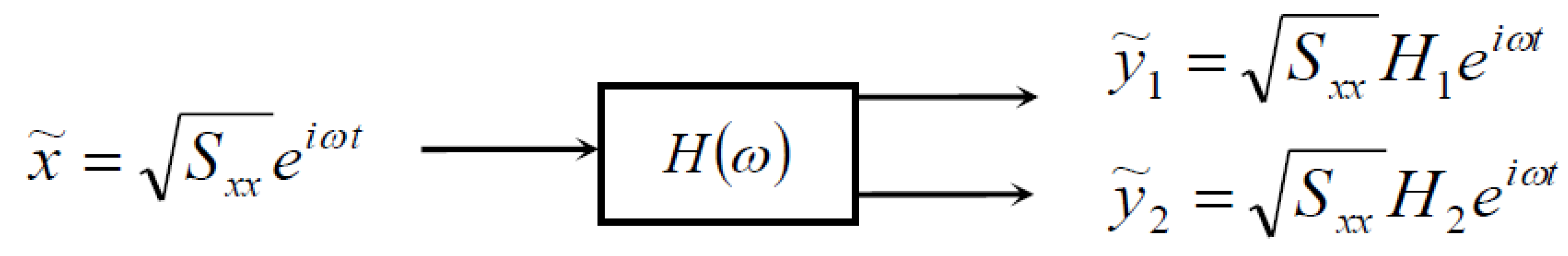
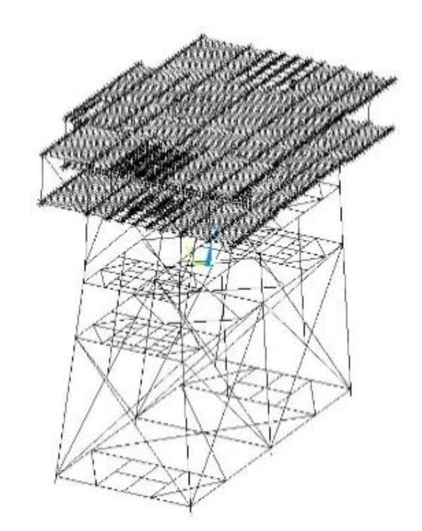
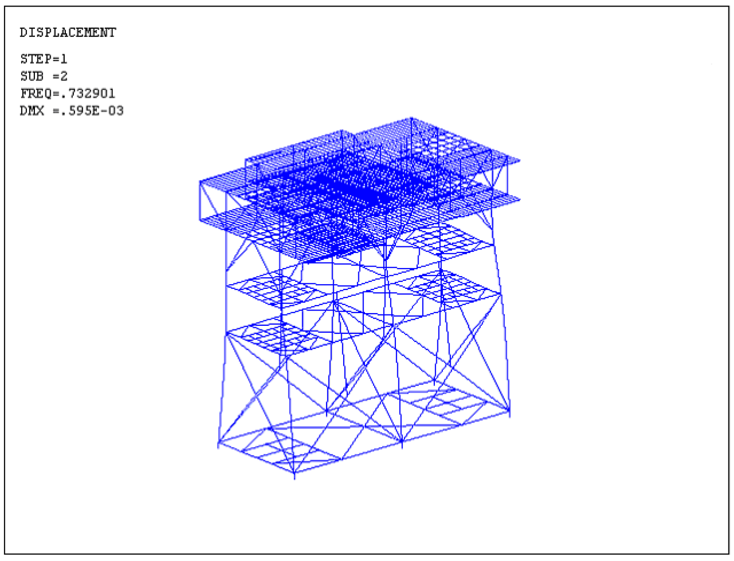
In this study, a novel simplified method for determining frequency domain responses of a jacket platform is proposed for used under random wave loads. The jacket platform is modeled as a simplified non-uniform cantilever beam subjected to an axial force. A pseudo-excitation approach associated with the Ritz method is applied to determine the responses of a jacket platform under random wave loads, including power spectral densities, variances and higher spectral moments of required responses, among others, without having to compute the normal modes. The procedure for defining the pseudo wave load is described in detail, with an example used to illustrate the results. The accuracy of the proposed method is verified by comparing the results obtained with those from a FEM model. The proposed method is robust and produces results with a certain precision, especially in the preliminary design stage where the information and material of a platform are insufficient for setting up a detailed three-dimensional model.

2. Determination of the Pseudo Wave Load

2.1. Practical Wave Spectrum

The random process of wave elevation η ( t ) is a zero-mean-valued stationary process whereby the statistical characteristics of waves can be determined by their power spectral density (PSD). Some commonly used wave spectra include the Neuman spectrum, Pierson–Moskowitz (P-M) spectrum, Bretschneider spectrum, and JONSWAP spectrum, among others. As the P-M spectrum was established based on adequate wave data collected in ocean environments, it has been widely used in the field of ocean engineering. The expression of the spectrum is given in the following
S η ( ω ) = 0.0081 g 2 ω 5 exp [ 0.74 ( g v a 19.5 ω ) 4 ]
where v a 19.5 is wind speed at an altitude of 19.5 m.

2.2. Random Waves

For structures comprising slender members that do not significantly alter the incident wave field, semi-empirical formulations such as the Morison’s equation may be adopted. The diameter of such slender members must be less than 20% of the relevant wave lengths and be small with respect to the distances separating the members. A hydrodynamic force acting normal to the axis of a cylindrical member, as given by Morison’s equation, is expressed as the sum of the force vectors as indicated in the following equation:
F ( t ) = F D ( t ) + F I   ( t )
where F ( t ) is the hydrodynamic force vector per unit length along the member that is acting normal to the axis of the member, F D ( t ) is the drag force vector per unit length, and F I ( t ) is the inertia force vector per unit length.
According to the linear wave theory (Yu et al. [17]), we have
F D   ( t ) = 8 / π σ u ( z ) K D ω cosh ( k z ) sinh ( k d ) η ( x , t )
F I   ( t ) = i K M ω 2 cosh ( k z ) sinh ( k d ) η ( x , t )
where η ( x , t ) = ( H / 2 ) cos ( k x ω t ) is the wave elevation, k = 2 π / L , ω = 2 π / T , K D = ρ w C D D / 2 and K M = ρ w C M π D 2 / 4 . Here, ρ w is the density of water, D is the diameter of the cylindrical cylinder, C D is the drag coefficient, C M is the inertia coefficient, H is the wave height, L is the wave length, T is the wave period, i is the imaginary unit and σ u ( z ) is the mean square deviation of horizontal particle velocity u ( t ) . By introducing the transfer functions for both the inertia and drag forces, where
T F I ( ω ) = F I   ( t ) η ( t ) = i K M ω 2 cosh ( k z ) sinh ( k d )
T F D ( ω ) = F D   ( t ) η ( t ) = 8 / π σ u ( z ) K D ω cosh ( k z ) sinh ( k d )
we have the wave force spectrum at the height of z as
S F ( ω ) = | T η F ( ω ) | 2 S η ( ω ) = ( | T F I ( ω ) | 2 + | T F D ( ω ) | 2 ) S η ( ω )      = { [ 8 / π σ u ( z ) K D ω cosh ( k z ) sinh ( k d ) ] 2 + ( K M ω 2 cosh ( k z ) sinh ( k d ) ) 2 } S η ( ω )
The P-M spectrum may be employed using the following approximate formulation (Yu et al. [17]):
σ u 2 ( z ) = H 2 1 / 3 16 ( ω cosh k z sinh k d ) 2
Substituting Equation (8) into Equation (7) yields
S F ( ω ) = [ ( 1 2 π K D H 1 / 3 ω 2 cosh 2 ( k z ) sinh 2 ( k d ) ) 2 + ( K M ω 2 cosh ( k z ) sinh ( k d ) ) 2 ] S η ( ω )
where K D = ρ w C D D / 2 and K M = ρ w C M π D 2 / 4 . Here, ρ w is the density of water, D is the diameter of the cylindrical cylinder, C D is the drag coefficient, C M is the inertia coefficient, k   =   2 π / L , ω   =   2 π / T , H is the wave height, L is the wave length, T is the wave period and H 1 / 3 is the significant height.

2.3. Pseudo-Excitation Method and Pseudo Wave Load

The Pseudo-Excitation Method (PEM) is an accurate and highly efficient approach for structural stationary/non-stationary random response analysis. The associated algorithm series have been developed since the early 1980s and applied to random vibration analyses of structures subjected to single/multiple and stationary/non-stationary random excitation. The advantage of the algorithm is in the solution of the response to the non-uniformly modulated and evolutionary random excitations. Each algorithm in this model series is an accurate and complete quadratic combination (CQC) method of combining maximum modal responses in which the cross-correlation quadratic terms between the participant modes and between the excitations have both been included. Such algorithms are easy to use as the structural stationary random response analysis is then reduced to an analysis of structural harmonic response, while structural non-stationary random responses can be readily computed in terms of any step-by-step integration scheme (Lin and Zhang [18]).
The PEM for the stationary single excitation problem may be represented as a linear system, as shown in Figure 1. The linear system is subjected to a zero-mean-valued stationary random excitation whose power spectral density (PSD) S x x ( ω ) has been specified. If y 1 ˜ = S x x ( ω ) H 1 ( ω ) e i ω t and y 2 ˜ = S x x ( ω ) H 2 ( ω ) e i ω t are two arbitrary stationary harmonic responses due to the pseudo harmonic excitation of x ˜ = S x x ( ω ) e i ω t then it can be readily verified that
y 1 ˜ * y 1 ˜ = S x x ( ω ) H 1 * ( ω ) e i ω t · S x x ( ω ) H 1 ( ω ) e i ω t = | H 1 ( ω ) | 2 S x x ( ω ) =   S y 1 y 1 ( ω )    
y 1 ˜ * y 2 ˜ = S x x ( ω ) H 1 * ( ω ) e i ω t · S x x ( ω ) H 2 ( ω ) e i ω t = H 1 * ( ω ) S x x ( ω ) H 2 ( ω ) =   S y 1 y 2 ( ω )
in which the variable with asterisk (*) represents its complex conjugate. This means the auto-PSD and cross-PSD functions of the two random responses y 1 ( t ) and y 2 ( t ) can be computed using their corresponding pseudo harmonic responses y 1 ˜ and   y 2 ˜ .
If the pseudo responses are two arbitrary harmonic response vectors, { y 1 ˜ ( t ) } and { y 2 ˜ ( t ) } , it can be similarly verified that the corresponding PSD matrices would be
{ y 1 ˜ } * { y 1 ˜ } T =   | S y 1 y 1 ( ω ) |
{ y 1 ˜ } * { y 2 ˜ } T =   | S y 1 y 2 ( ω ) |
According to the above-mentioned PEM and Equation (9), the pseudo wave load can be formulated as
F ˜ ( z , t ) = S F ( ω ) e i ω t = ( 1 2 π K D H 1 3 ω 2 cosh 2 ( k z ) sinh 2 ( k d ) ) 2 + ( K M ω 2 cosh ( k z ) sinh ( k d ) ) 2   S η ( ω ) e i ω t

3. Solutions of Equation of Motion

The partial differential equation governing the bending motion with transverse displacement w ( z , t ) of a cantilever beam subjected to an axial force T and wave load is
ρ A ( z ) w   ¨ + c ( z ) w ˙ + [ E I ( z ) w ] + T w = F ( z , t )
where E I ( z ) is flexural rigidity and ρ A ( z ) is mass per unit height, both of which may vary with position z . The double prime (″) denotes the second-order partial derivative of the displacement function w with respect to the beam height z. The wave load F ( z , t ) , which may vary with position and time, causes motion of the beam. The boundary conditions at the two end points of a cantilever beam at are
( w ) z = 0 = 0 , ( w z ) z = 0 = 0 , ( E I 2 w z 2 ) z = L = 0 , z ( E I 2 w z 2 ) z = L = 0
If the beam is initially in static equilibrium, then the initial conditions are
w ( z , 0 ) = 0 ,    w ˙ ( z , 0 ) = 0
Substituting Equation (14) into Equation (15) leads to
ρ A ( z ) w ˜ ¨ + c ( z ) w ˜ ˙ + [ E I ( z ) w ˜ ] + T w ˜ = F ˜ ( z , t )
where w ˜ represents the corresponding pseudo displacement due to the pseudo wave load F ˜ ( z , t ) .
With the use of the Ritz method, the displacements can be expressed as a linear combination of several shape vectors φ j ( z ) as
w ˜ ( z , t ) = j = 1 q y ˜ j ( t ) φ j ( z ) = [ ] { y ˜ }
By substituting Equation (19) into Equation (18), multiplying [ ] T by both sides of the equation, and integrating z from zero to L , the equation of motion gives
[ M ] { y ˜ ¨ } + [ C ] { y ˜ ˙ } + [ R ] { y ˜ } + [ K 1 ] { y ˜ } = { P } e i ω t
where
[ M ] = 0 L ρ A ( z ) [ ] T [ ] d z
[ C ] = 0 L c ( z ) [ ] T [ ] d z
[ R ] = 0 L [ ] T [ E I ( z ) [ ] ] d z
[ K 1 ] = T 0 L [ ] T [ ] d z
{ P } = S η ( ω ) 0 L [ ] T ( 1 2 π K D H 1 3 ω 2 cosh 2 ( k z ) sinh 2 ( k d ) ) 2 + ( K M ω 2 cosh ( k z ) sinh ( k d ) ) 2   d z
For computational convenience, Equations (23) and (24) are rearranged twice via an integration of parts and by utilizing the boundary conditions of the cantilever beam to have
[ R ] = 0 L E I ( z ) [ ] T [ ] d z
[ K 1 ] = T 0 L [ ] T [ ] d z
Equation (20) can be rewritten as
[ M ] { y ˜ ¨ } + [ C ] { y ˜ ˙ } + [ K ] { y ˜ } = { P } e i ω t
where [ K ] = [ R ] + [ K 1 ] , [ M ] is the generalized mass coefficient and [ C ] and [ K ] are the generalized damping and generalized stiffness coefficients, respectively. Because the Ritz vectors are generally different from the natural modes, [ M ] , [ C ] and [ K ] are not diagonal matrices. Since the generalized load { P } e i ω t on the right side of Equation (28) is expressed as a harmonic excitation, the solution can be presented in the following form:
{ y ˜ ( t ) } = ( { y ˜ r } + i { y ˜ i } ) e i ω t
where the subscripts r and i denote the real and imaginary parts of the complex values, respectively. Substituting Equation (29) into Equation (28) and separately collecting the terms in the real and imaginary parts of the equation, we have
[ E ] { y ˜ r } + [ D ] { y ˜ i } = { P r }
[ D ] { y ˜ r } + [ E ] { y ˜ i } = { P i }
where
[ E ] = [ K ] ω 2 [ M ] , [ D ] = ε [ K ]
in which ε is the damping coefficient. Once { y ˜ r } and { y ˜ i } are determined, the displacement w ( z , t ) can be computed according to Equations (19) and (29). The PSD can then be evaluated by
S w w ( z , ω ) = | w ( z , t ) | 2 ,         S M M ( z , ω ) = | M ( z , t ) | 2
After the PSD of the structural response, denoted as S r ( ω ) , is determined, the associated spectral moments can be readily obtained. The zeroth moment and the second moment are the most useful ones and they are
λ 0 , r = σ r 2 = 0 + S r ( ω ) d ω
λ 2 , r = 0 + ω 2 S r ( ω ) d ω

4. Case Study

4.1. Natural Vibration Characteristics

A three-deck offshore jacket platform was selected as a test structure to demonstrate the proposed calculation procedure. Simulations of a three-dimensional FEM model set up for the three-deck offshore jacket platform were also carried out to generate results for comparisons. The relevant geometries and material properties of the structure are given as follows. The total height of the platform L = 68 m and the water depth was 23 m. The jacket platform was 38 m high, 48 × 20 m at the base and 48 × 14 m at the top. The inclination of six main tubular members was set at a slope of 10:1 and the sectional dimension was Ф1333 × 19 mm. Twelve braces with a Ф762 × 16 mm section at the base and Ф610 × 13 mm at the top were used. The mass of the three decks, from lower to upper, were 93, 267 and 1231 tons, respectively. All structural members were made of steel with a mass density of ρ   =   7800   kg / m 3 , Young’s modulus of E = 210   GPa and Poisson’s ratio of υ = 0.3 .
A FEM model was established as shown in Figure 2. The entire platform was modeled as a plate–girder composite structure where the decks and other platform components were modeled as shell elements and the frame and jacket were set up as beam elements using the software ANSYS (USA). The element numbers are tabulated in Table 1. The mesh size was 0.25 m.
The pile group effects between the adjacent legs were neglected, as the spacing between the jacket legs was far larger than 5~10 times that of the diameter of the legs. The impact of added mass was considered and applied to the corresponding node on the underwater segment of the beam element. The platform model was assumed to be fixed at end points of the piles that were below the bed soil surface at a depth six times the diameter of the leg. Figure 3 shows the first-order natural frequency of the platform obtained using the FEM model.
To carry out the proposed approach, the 3-D platform mentioned above was simplified as a cantilever beam model. The inertia moment I ( z ) = 55-z and density ρ = 7800 kg/m3. Assuming water was attached to the structure uniformly, the sectional mass per unit height was ρ A ( z ) = 15545-91z. The natural frequencies of the simplified model with (case 1) and without (case 2) shear effects were calculated and compared with those obtained with the 3-D FEM model in Table 2. It can be seen from Table 1 that the frequency results from the simplified model closely match those from the 3-D FEM model. It is concluded that the accuracy of the results obtained using the present simplified model meet the requirements of an initial assessment of the structure in the preliminary design stage.

4.2. Random Responses

In this case, the P-M spectrum was used and v a 19.5 = 16.24 m/s. Accordingly, the significant height was calculated as H 1 / 3 = 5.63 m by means of conversion. A q-dimensional Ritz vector is defined as R 1 ( q ) = [ η 2 , η 3 , , η q + 1 ] , in which η = z/L. Apparently, the elements in the Ritz vector are linearly independent and satisfy the geometric boundary conditions. In this sample calculation, ε = 0.05 and q = 3. Figure 4 shows the PSD of jacket-top displacement and the bending moment of the jacket at the mud line. Here, the red line represents the results obtained using a finite element model, while the black line denotes the results obtained using the proposed simplified method. Table 3 lists the corresponding variances σ r 2 and second spectral moments λ 2 , r that were obtained from the FEM model and with the use of the proposed simplified method. Table 4 lists the extremums of jacket-top displacement and the number of occurrences when a wave lasted for 60 seconds.
With reference to the PSD of jacket-top displacement and PSD of the bending moment at the mud line, as shown in Figure 4, the largest jacket-top displacement obtained using FEM was 1.89 × 10⁻⁹ m2s and was observed at 0.52 rad/s. Meanwhile, as determined using the proposed simplified method it was 1.80 × 10⁻⁹ m2s and observed at 0.50 rad/s. Similarly, the largest PSD of the bending moment at the mud line obtained using the FEM was 5.45 × 10¹¹ N2m2s at a frequency of 0.52 rad/s, while for the simplified method it was 5.42 × 10¹¹ N2m2s at 0.50 rad/s. It may be noted that the largest PSD and corresponding frequency calculated using the simplified method were marginally lower than those calculated using FEM. Moreover, the two figures by FEM and the simplified method showed not only very similar trends, but the peak values of PSDs were also in agreement with each other. Hence, it may be concluded that the proposed simplified model is able to provide a reliable initial assessment of the structure in the preliminary design stage.
Regarding spectral moments, it can be seen in Table 2 that the results obtained by using the simplified method were also in agreement with those of FEM, although the results contained very limited differences. The spectral moments were predicted with reasonable accuracy, and met the required engineering precision. Considering the complexity of the jacket platform, the simplified model proposed in this paper could be a practical analysis tool for offshore engineering design practices.

5. Conclusions

Based on the findings of the investigation on a three-deck jacket platform using the proposed simplified approach, the following conclusions can be drawn:
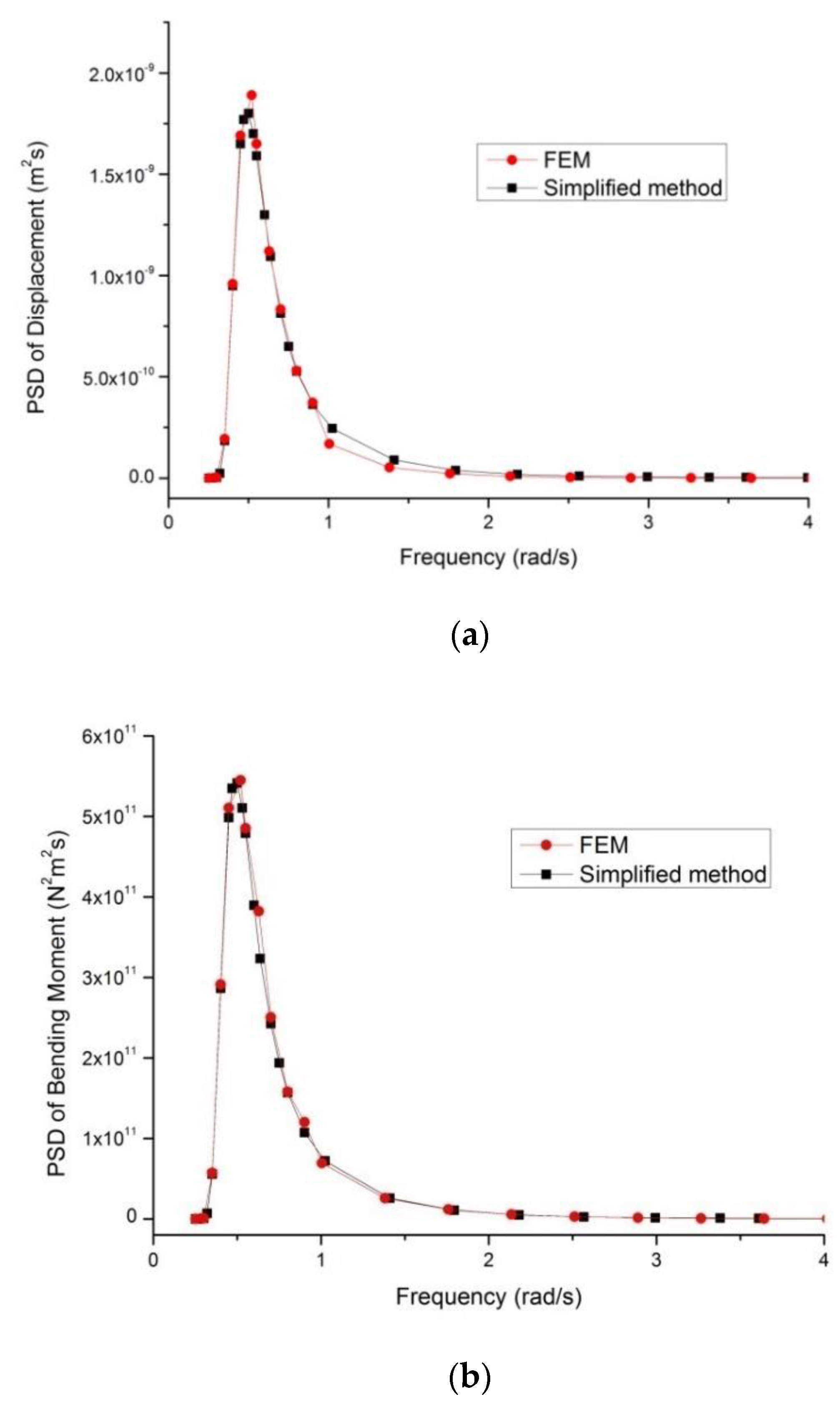
(1) The proposed simplified method could be used successfully to perform an analysis of frequency domain responses for a jacket platform under random wave loads. The findings show that the simplified method, when compared with a comprehensive numerical model, can provide the reliable and accurate predictions required by the engineering profession. The simplified method provides a simple, effective and convenient frequency domain dynamic analysis for jacket offshore platforms. It is suggested that the method be used in the engineering practice with results adapted to standard or design guidelines.
(2) The pseudo-excitation method combined with the classical Ritz method was demonstrated to be able to determine the frequency domain responses of structures under random wave loads. The proposed approach produced highly accurate results and was computationally efficient. Under structural dynamic analysis, the normal modes of structures do not need to be calculated, which is a computational advantage and is very convenient for analyzing complex structures.

Author Contributions

Conceptualization, X.H.; methodology, B.Z. and X.H.; writing—review and editing, W.Q.

Funding

This research was funded by the LiaoNing Revitalization Talents Program, grant number XLYC1807190; Liaoning Provincial Natural Science Foundation Guidance Project, grant number 20180550186; Open Project Funding of State Key Laboratory of Coastal and Offshore Engineering, Dalian University of Technology, grant number LP1906; and Fundamental Research Funds for the Central Universities.

Conflicts of Interest

The authors declare no conflict of interest.

References

  1. Sunder, S.S.; Connor, J.J. Sensitivity analyses for steel jacket offshore platforms. Appl. Ocean Res. 1981, 31, 3–26. [Google Scholar] [CrossRef]
  2. Gudmestad, O.T.; Moe, G. Hydrodynamic coefficients for calculation of hydrodynamic loads on offshore truss structures. Mar. Struct. 1996, 9, 745–758. [Google Scholar] [CrossRef]
  3. Karunakaran, D.; Baerheim, M.; Leira, B.J. Measured and simulated dynamic response of a jacket platform. In Proceedings of the Sixteenth Offshore Mechanics and Arctic Engineering Conference, II, Yokohama, Japan, 13–17 April 1997; pp. 157–164. [Google Scholar]
  4. Horr, A.M.; Safi, M. Full dynamic analysis of offshore platform structures using exact Timoshenko pipe element. J. Offshore Mech. Arct. Eng. 2003, 125, 168–175. [Google Scholar] [CrossRef]
  5. Mostafa, Y.E.; El Naggar, M.H. Response of fixed offshore platforms to wave and current loading including soil-structure interaction. Soil Dyn. Earthq. Eng. 2004, 24, 357–368. [Google Scholar] [CrossRef]
  6. Patil, K.C.; Jangid, R.S. Passive control of offshore jacket platforms. Ocean Eng. 2005, 32, 1933–1949. [Google Scholar] [CrossRef]
  7. Elshafey, A.A.; Haddara, M.R.; Marzouk, H. Dynamic response of offshore jacket structures under random loads. Mar. Struct. 2009, 22, 504–521. [Google Scholar] [CrossRef]
  8. Golafshani, A.A.; Gholizad, A. Friction damper for vibration control in offshore steel jacket platforms. J. Constr. Steel Res. 2009, 65, 180–187. [Google Scholar] [CrossRef]
  9. Golafshani, A.A.; Bagheri, V.; Ebrahimian, H.; Holmas, T. Incremental wave analysis and its application to performance-based assessment of jacket platforms. J. Constr. Steel Res. 2011, 67, 1649–1657. [Google Scholar] [CrossRef]
  10. Moharrami, M.; Tootkaboni, M. Reducing response of offshore platforms to wave loads using hydrodynamic buoyant mass dampers. Eng. Struct. 2014, 81, 162–174. [Google Scholar] [CrossRef]
  11. Mao, D.; Zhong, C.; Zhang, L.; Chu, G. Dynamic response of offshore jacket platform including foundation degradation under cyclic loadings. Ocean Eng. 2015, 100, 35–45. [Google Scholar] [CrossRef]
  12. Abhinav, K.A.; Saha, N. Coupled hydrodynamic and geotechnical analysis of jacket offshore wind turbine. Soil Dyn. Earthq. Eng. 2015, 73, 66–79. [Google Scholar] [CrossRef]
  13. Wei, K.; Myers, A.T.; Arwade, S.R. Dynamic effects in the response of offshore wind turbines supported by jackets under wave loading. Eng. Struct. 2017, 142, 36–45. [Google Scholar] [CrossRef] [Green Version]
  14. Zhou, B.; Han, X.; Tan, S. A Simplified Computational Method for Random Seismic Responses of a Jacket Platform. Ocean Eng. 2017, 82, 85–90. [Google Scholar] [CrossRef]
  15. Asgarian, B.; Mohebbinejad, A.; Soltani, R.H. Simplified method to assess dynamic response of jacket type offshore platforms subjected to wave loading. In Proceedings of the Twenty-Third Offshore Mechanics and Arctic Engineering Conference, Vancouver, BC, Candan, 20–25 June 2004; pp. 685–692. [Google Scholar]
  16. Zhou, B.; Guo, W.; Han, X.; Tan, S. Random seismic response analysis of jacket structure with Timoshenko’s beam theory. Ships Offshore Struct. 2016, 11, 438–444. [Google Scholar] [CrossRef]
  17. Yu, Y.; Liu, S. Random Wave and Its Applications to Engineering, 4th ed.; Dalian University of Technology Press: Dalian, China, 2000. [Google Scholar]
  18. Lin, J.H.; Zhang, Y.H. Pseudo Excitation Method of Random Vibration; Science Press: Beijing, China, 2004. [Google Scholar]
Figure 1. Basic theory of PEM.
Jmse 07 00328 g001
Figure 2. FEM of jacket platform.
Jmse 07 00328 g002
Figure 3. The first order natural frequency.
Jmse 07 00328 g003
Figure 4. Results for (a) PSD of jacket-top displacement and (b) bending moment of the jacket at the mud line.
Jmse 07 00328 g004
Table 1. Element type and element number.
Element TypeArea ElementBeam ElementMass ElementNode
Element No.35,15232,806230847,420
Table 2. Comparisons of natural frequencies.
CasesMode Shape3-D FEM Model
(Hz)
Simplified Model
(Hz)
1Y-direction0.730.83
2Y-direction2.452.63
Table 3. Several spectral moments.
ItemJacket-Top Displacement (m2s)Bending Moment of Jacket at Mud Line (N2m2s)
Simplified MethodFEMSimplified MethodFEM
σ r 2 7.15 × 10−107.23 × 10−102.12 × 10112.20 × 1011
λ 2 , r 7.49 × 10−107.60 × 10−101.92 × 10112.01 × 1011
Table 4. Extremums for the jacket-top displacement.
Wave Duration(s)Simplified MethodFEM
Max. Displacement (mm)Number of OccurrencesMax. Displacement (mm)Number of Occurrences
6014.794914.7879

