Article

Deployment and Maintenance of Wave Energy Converters at the Lysekil Research Site: A Comparative Study on the Use of Divers and Remotely-Operated Vehicles

Division for Electricity, Uppsala University, Box 534, 75121 Uppsala, Sweden
*
Author to whom correspondence should be addressed.
J. Mar. Sci. Eng. 2018, 6(2), 39; https://doi.org/10.3390/jmse6020039
Submission received: 15 February 2018 / Revised: 20 March 2018 / Accepted: 26 March 2018 / Published: 12 April 2018
(This article belongs to the Special Issue Advances in Ocean Wave Energy Conversion)

Abstract

:
Ocean renewable technologies have been rapidly developing over the past years. However, current high installation, operation, maintenance, and decommissioning costs are hindering these offshore technologies to reach a commercialization stage. In this paper we focus on the use of divers and remotely-operated vehicles during the installation and monitoring phase of wave energy converters. Methods and results are based on the wave energy converter system developed by Uppsala University, and our experience in offshore deployments obtained during the past eleven years. The complexity of underwater operations, carried out by either divers or remotely-operated vehicles, is emphasized. Three methods for the deployment of wave energy converters are economically and technically analyzed and compared: one using divers alone, a fully-automated approach using remotely-operated vehicles, and an intermediate approach, involving both divers and underwater vehicles. The monitoring of wave energy converters by robots is also studied, both in terms of costs and technical challenges. The results show that choosing an autonomous deployment method is more advantageous than a diver-assisted method in terms of operational time, but that numerous factors prevent the wide application of robotized operations. Technical solutions are presented to enable the use of remotely-operated vehicles instead of divers in ocean renewable technology operations. Economically, it is more efficient to use divers than autonomous vehicles for the deployment of six or fewer wave energy converters. From seven devices, remotely-operated vehicles become advantageous.

1. Introduction

1.1. Overview

Offshore renewable energy conversion technologies, offshore wind, tidal, and wave, are developed broadly around the world, but some remain at an experimental stage in contrast to the level of exploitation of the offshore oil and gas (O&G) industry. Today’s techniques used to deploy and maintain an offshore renewable power plant are predominantly imitating the O&G industry [1]. However, not all are suitable for the offshore renewable energy sector, which is lacking specific operation and maintenance strategies for the different devices [2]. The offshore wind sector, for example, now has developed specific vessels, as ships used in O&G were not compliant [1].
In O&G, robotics were first used to address the issues related to deep sea and ultra-deep sea plants. At great depths diving becomes hazardous and also very costly and is thereby not suitable [3]. The use of robots and, in particular, of remotely-operated vehicles (ROVs), started to increase and those vehicles are now used for many applications, such as inspection (valve position and gauge reading), monitoring (check for leakage, surface conditions, acoustic anomalies), maintenance (cleaning, sampling, refilling), and heavier operations, such as drilling, welding, or cutting [4]. In the offshore wind sector robotics are used for inspection and monitoring, as well as seabed studies prior to commissioning, but the deployment of offshore wind farms still uses ROVs in a limited manner.
Conducting an offshore renewable energy operation on wave energy converters (WECs), such as a deployment or maintenance work, includes various tasks, for example, removal of lifting slings and shackles, cable connections and investigation, and disconnection of pressurization hoses. Such work can be conducted in three manners: one possibility is to use divers, a second is to use underwater robots, and the third combines both divers and ROVs. In this article we study those three approaches and present their economic and technical advantages and disadvantages.

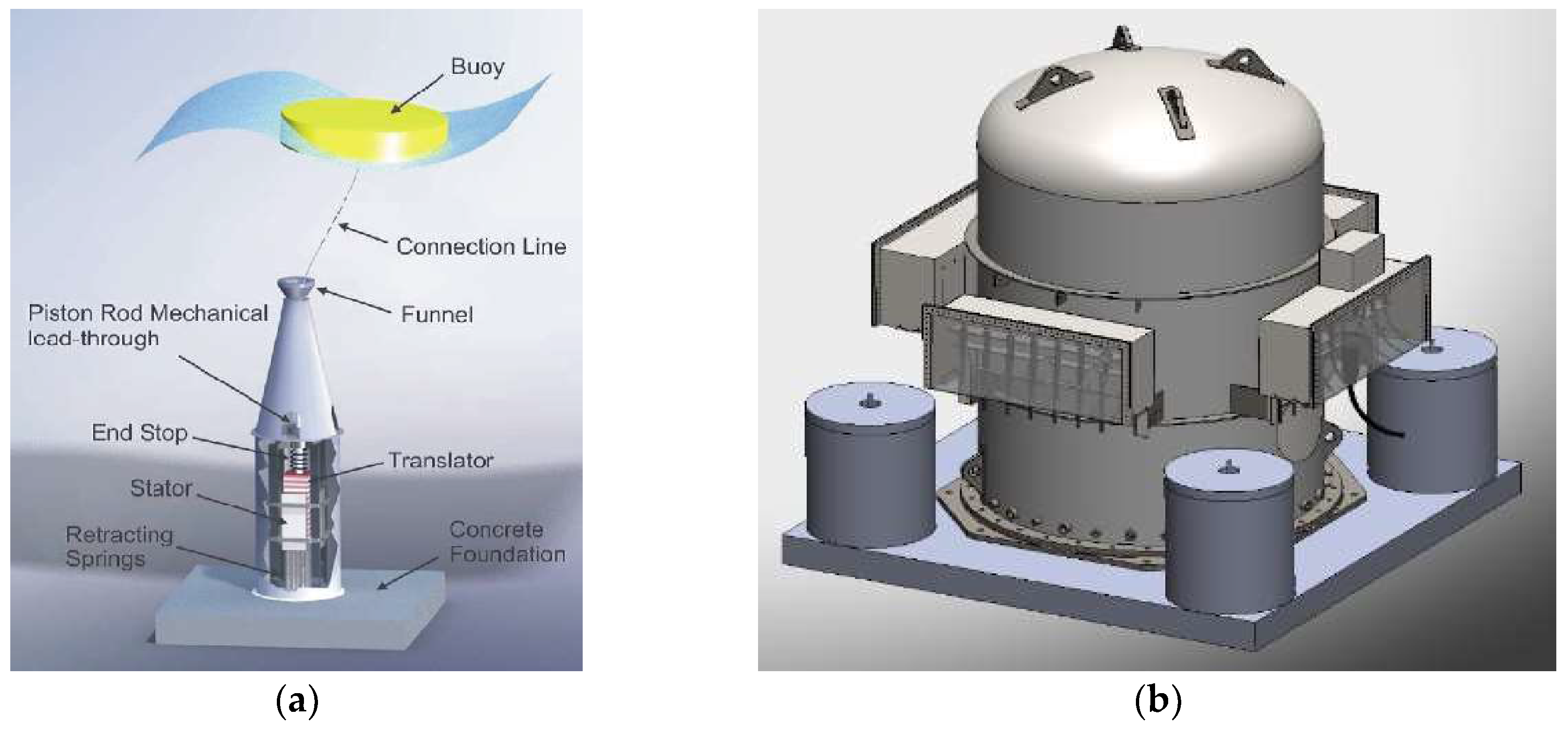
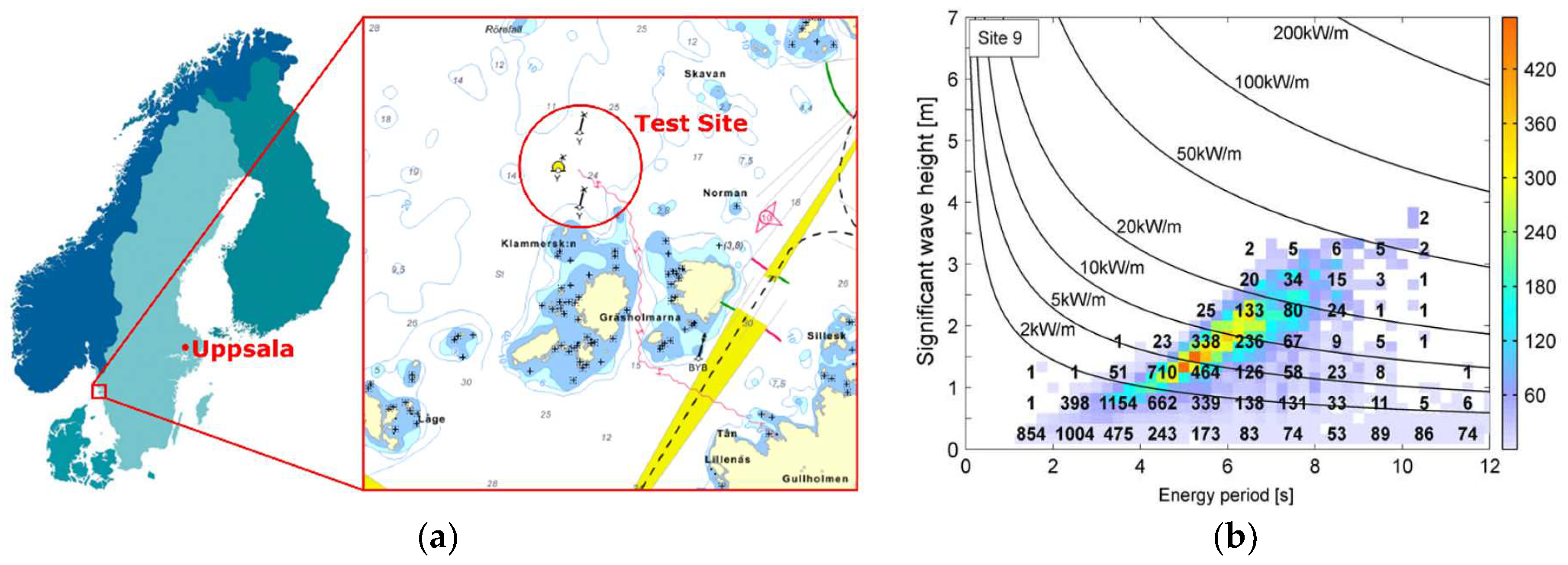
1.2. Lysekil Research Site and Wave Energy Converter Concept

Since 2002, research at Uppsala University (UU) within the Lysekil project has resulted in the development of a WEC concept presented in Figure 1a. The first full scale WEC was installed in 2006 [5]. From 2006 to present, an additional fourteen WECs and two marine substations (MSs) have been deployed and tested at the Lysekil Research Site (LRS) [6,7]. The second version of the MS can be seen in Figure 1b.
The UU WEC is an offshore device of a point absorbing type, with a direct-driven linear generator power take off. The generator is of permanent magnet type with either ferrite or neodymium magnets, depending on the design. A buoy at the surface is directly connected via a connection line to the translator. That way, the wave’s motion is converted to the translator motion. This generator model is designed to operate in water depths of 20 to 100 m [8]. To even the pressure in- and outside of the device, and to prevent it from oxidizing, the WEC is manually pressurized while being submerged, with 0.1 bar of nitrogen gas for every meter of submersion. For depths of 20–25 m, such as in the LRS, the final inner pressure of a WEC will be approximately 3.5 bars. A single WEC can provide limited power, therefore, a cluster of generators needs to be interconnected to a marine substation in order to increase the power output [9,10]. Such a cluster could be as large as 100 WECs, with ten MSs. As an example, a typical power matrix for the UU WEC can be seen in [11]. The MS controls each generator individually, optimizes the power and damping, and combines the electrical power from the WECs. It also rectifies every WEC’s current to direct current (DC), then converts it to alternating current (AC) for grid connection. This also reduces the number of sea cables and its associated expense, which is one of the largest in the Lysekil project [12,13,14,15].
The offshore deployments of UU have taken place at the LRS (Figure 2), which is located at the Swedish west coast, about 100 km north of Gothenburg. The total deployment area is 0.5 km2, its depth is approximately 25 m, and the seabed consists of mostly firm sandy silts, which makes the sea bottom smooth for the WEC’s placement [16]. Moreover, its comparably shallow depth allows easy access for divers during the deployment and maintenance of the devices. Additionally, since the site is located only 2 km from shore, the site enables simplified deployment methods and lower costs [17]. The wave climate matrix of the LRS can be seen in Figure 2b [18].

1.3. Deployment and Monitoring of WECs, Buoy Lines, and Sea Cables

Offshore deployments of WECs and MSs are complex procedures that need precise planning, experienced crew and in many cases, specialized equipment. The main steps in a deployment are: (a) the device preparation; (b) transportation to the deployment location; (c) immersion into the water; (d) electrical connection to the MS; and (e) connection to the buoy. Divers or ROVs participate in the last three steps, including underwater cable connections and disconnections of pressurization hose, slings, and shackles used in the installation of the device [19].
Although the WECs developed at UU are designed to be maintenance-free, meaning that no maintenance should be needed during the whole lifetime (20–25 years) of the generator [20], they may need to be monitored from time to time for biofouling prevention and observation. The parts in demand of maintenance are: safety lines, various underwater cables, connection lines, funnels, and shackles. The power cable, from the MS to shore, is one of the most expensive parts in such an installation (ca. 150,000 €). The cable requires periodic monitoring to detect possible damage, such as cracks, twisting, and abrasion (due to high forces/motions), especially in shallow waters where wave motion is important. The signal cable is the most sensitive part. Due to its thinness it can easily be damaged by rocks or boat anchors, especially in shallow water and shorelines, where the wave action is significant. The connection line and shackles, which connect the buoy to the generator and are subjected to strong forces, need a regular inspection as well. Damage to those parts could result in a cut loose buoy. The same applies for the safety line which additionally connects the buoy to the generator for safety reasons.

1.4. Paper Contribution and Outline

At the current stage, high installation, operation, maintenance and decommissioning costs are preventing most of the WEC technologies from reaching commercialization [21,22]. These costs could possibly be lowered by making some of the procedures automated with the use of ROVs. To this day, few articles have been published concerning the deployment and operation and maintenance of wave or tidal energy devices [23,24] and of offshore renewable energy conversion technologies [25], while robotics are increasingly present in offshore O&G applications [3,4,26,27]. The development of robotic and automated tools is essential to enhancing the deployment phase of any offshore renewable energy device and this paper offers a first comparison of the use of divers and ROVs in these operations. The purpose of this paper is to compare the offshore deployment and maintenance of WECs, buoys, and sea cables while (a) employing divers and (b) employing ROVs, and to study what developments are necessary in order to increase and improve the use of ROVs. This comparison is both qualitative and quantitative, economic and technical, and is based on eleven years of experience in offshore deployments. All presented time estimations and costs for the case studies show optimal procedures, meaning no adversities or time losses occurred.
The time data (in hours) and costs (in euros, €) presented in the paper are obtained from experience of the UU wave energy group during offshore operations. The various costs appear in euros, € where: 1 EUR = 1.24110 USD (as for 6 March 2018).
In this paper, Section 2 provides background knowledge on commercial diving and underwater ROVs. Section 3 and Section 4 present the methods of and, correspondingly, the results from, and discussion on, the technical and economic comparative study. Finally, Section 5 summarizes the conclusions.

2. Background on Commercial Diving and Remotely Operated Vehicles (ROVs)

2.1. Introduction to Commercial Diving

2.1.1. Background

The use of commercial diving within construction work has a long history, dating back to the 18th century and was enabled along with many other new technical discoveries [28]. More recently, and with more advanced equipment, commercial diving has been applied within the shipping industry for inspection and maintenance, e.g., in the offshore O&G industry and in the fish farming industry [29,30,31,32]. As the marine renewable energy sector of wind, wave, and tidal power emerged and developed, commercial diving finds a new utilization within the offshore renewable energy conversion technologies sector [33].
Regulations, certificates, and training of commercial diving vary between countries. However, in 1973 the European standard from the European Diving Technology Committee [34] was established in order to promote proper and safe standards for commercial diving, provide a means of improvement, if appropriate, and coordinate, where possible, the different standards which existed around the world.

2.1.2. Costs of Dive Missions

The costs for hiring a dive team vary significantly depending on the project scope and the conditions for the task. A comparison of three Swedish companies shows differences in price, such as 66 € (NDE Offshore AB), 78 € (MarCon Technik AB), and 98 € (Marine Works) for one diver/hour. The working depth of the project is one of the most crucial parameters. An example of Swedish regulations and their change in safety provisions with different water depth, and thereby an increase in costs, follows: According to the Swedish Diving Work guidelines [34], safety provisions increase with larger operational water depth. In depths of more than 30 m, divers require more advanced certificates. If the planned dive is deeper than 40 m, the decompression time exceeds 31 min or the dive includes staged decompression, additional safety conditions must be complied. Apart from a shorter dive time [35] a decompression chamber is required onboard or reachable within 30 min after completing the dive. This regulation can make a dive mission three to four times more expensive compared to shallower and shorter dives (personal communication with M. Häggström, Marine Works, Sweden, November 2017). Having a decompression chamber on site requires an appropriate boat and more personnel, which results in higher costs. Furthermore, if a decompression activity in the chamber occurs, no diving can be performed during that time.
From experiences during UU offshore deployments of 20–25 m depth, a four-diver team can make a maximum of seven dives per day with a total dive time of 3.5 h/day. Dive time depends on work depth, previous number of conducted dives, and surface break between dives. Moreover, the mean diving time has been around 25 min per dive.

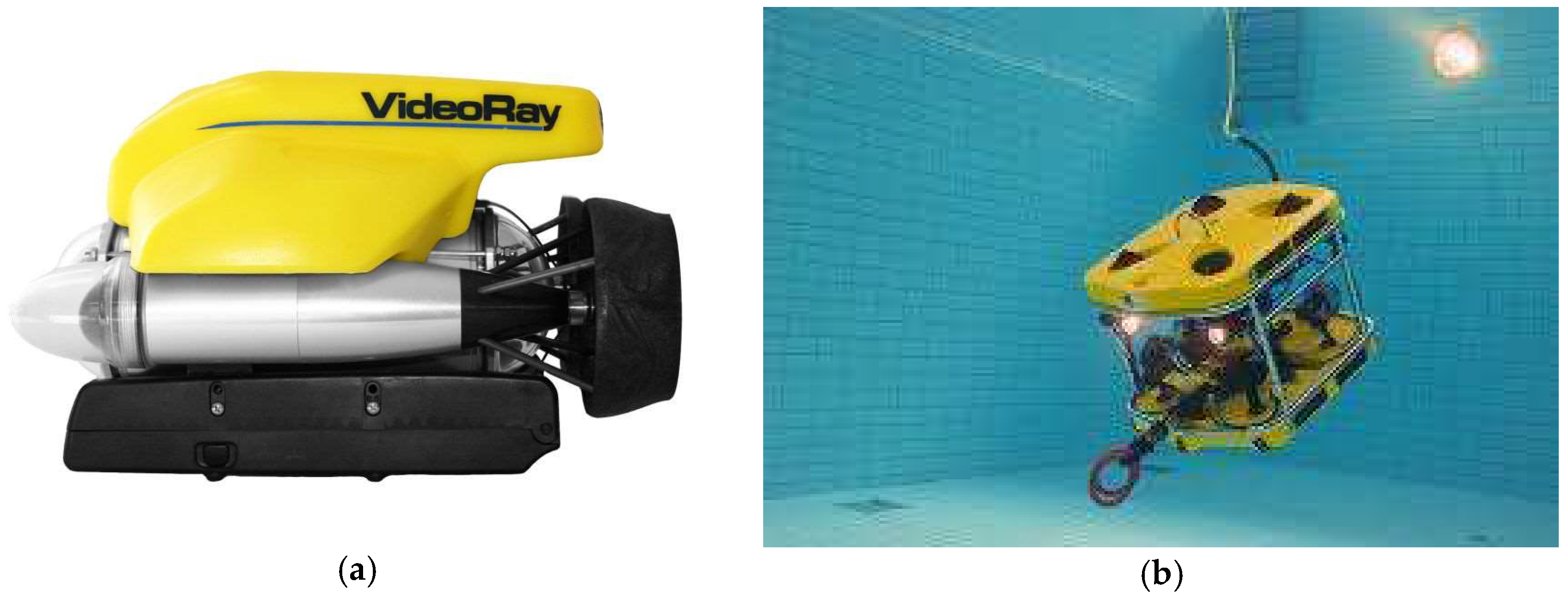
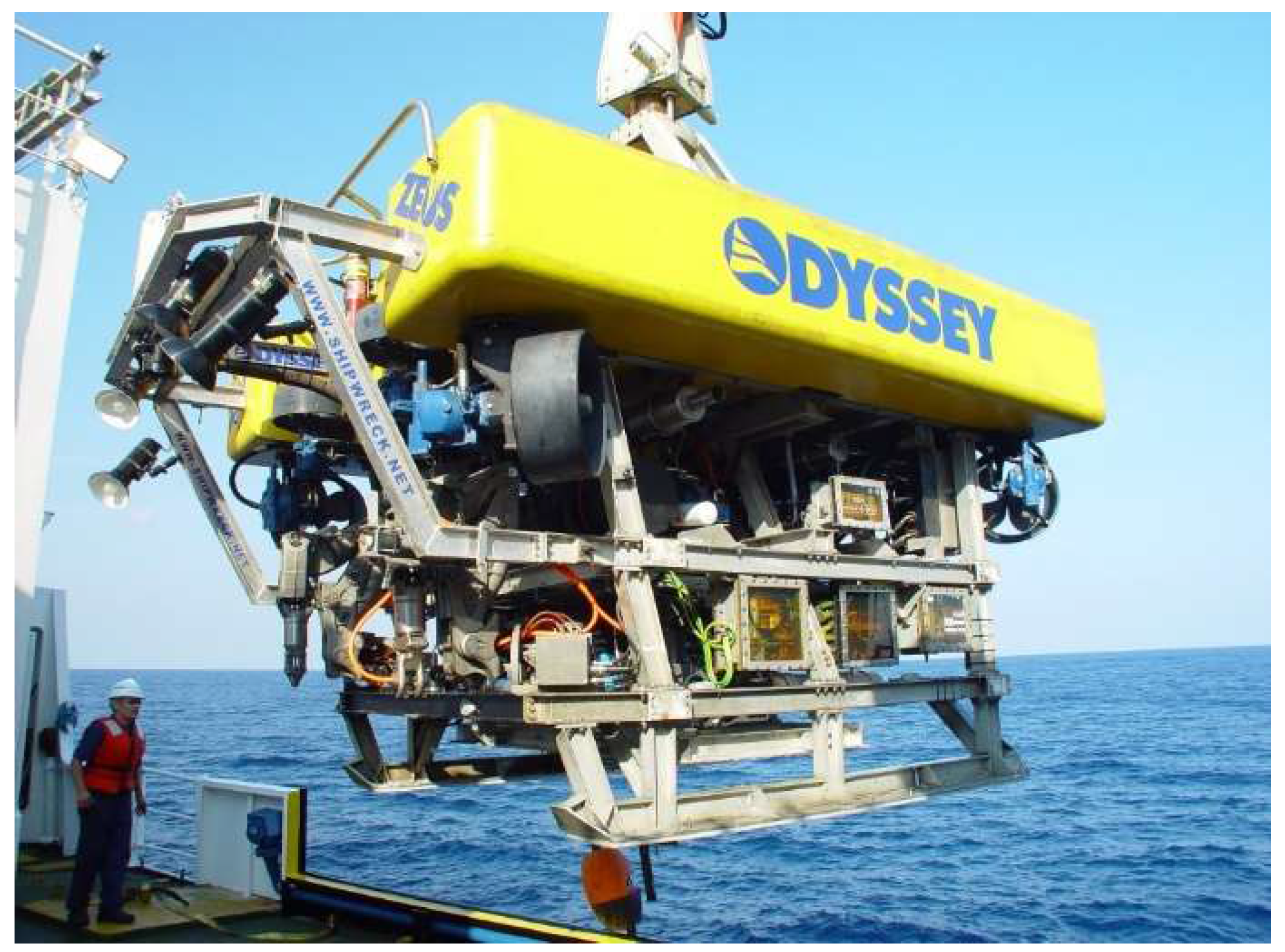
2.2. Introduction to Underwater Robots

Underwater vehicles are separated between manned and unmanned submersibles [36]. Unmanned vehicles are divided into ROVs and Autonomous Underwater Vehicles (AUVs) [37]. The main difference between the two classes is the presence of a tether allowing communication, and, in most cases, power supply, between the robot and the surface vessel. With a limited power supply, AUVs are typically used for observation or tasks requiring small forces. On the contrary, having access to an unlimited power supply, ROVs can carry out a large array of operations, from light to heavy, depending on the vehicle’s size. ROVs can be divided into three main categories: observation, medium, and working class [38]. The observation category includes, but is not limited to, any small ROV, typically with onboard power, whose tether is used for communication only [39]. Observation ROVs are usually highly maneuverable and small in size with good hydrodynamic properties, which results in low drag and little added mass. An example of such an ROV is the Videoray Pro 4 and the Ocean Modules V8 Sii (Figure 3).
The working class category includes large vehicles, which are intended to perform specific tasks but are usually limited in maneuverability. They are bulky and slow, not hydro-dynamically optimized, especially due to their heavy and thick tether designed for high power contact. On the other hand, that tether gives them access to a large amount of power and they can consequently perform heavy tasks, such as drilling, digging, lifting, or dragging. Their size allows them to carry multiple equipment and sensors simultaneously which makes them multifunctional. Working-class vehicles are generally equipped with either multi-tools and can thereby carry out a multitude of operations, as the ZEUS ROV in Figure 4, or with a single tool that requires large forces for specific tasks.
Medium-class ROVs are typically used for collecting samples or perform light tasks that require middle-range displacements and light forces. They usually have one tool onboard and are meant to perform one single and repetitive task. Examples of those tasks are collecting samples, or grasping and carrying lightweight or small items. This type of ROV is being developed with the rise of innovative technologies in electronics, allowing more onboard power and, hence, a thinner tether for better mobility and maneuverability of the vehicle without affecting the thrust requirements. Moreover, the costs of purchasing and maintaining a vehicle decrease with the reduction in price of electronic components, mechanical parts, and batteries. Consequently, it is of great interest to study the possibility of using a medium-class ROV for WEC deployments at the LRS.
Both AUVs and ROVs require a trained crew to be operated. The size of the team varies with the tooling of the robot (number of cameras, arms, and thrusters), its size, and the task it is used for: a predetermined and repetitive operation, complex work with multiple tasks, or a task utilizing the collaboration of several ROVs. The size of the crew varies from two persons for a small observation-class ROV with well-trained operators, to five or more for a working-class vehicle. Typical crew tasks are tether management, steering of the vessel and control of the onboard tools.
The benefits of using ROVs instead of divers are multiple. ROVs can work at great depths (several thousands of meters) while divers are much more limited. At depths of 30 m or more, the need for special equipment makes the operation significantly more expensive with divers than with ROVs. Operation time is theoretically not limited as long as a ROV pilot is available. There is minimal risk of injury for the ROV pilot compared to a significantly higher risk related to diving activities.
There are, however, factors limiting the work possibilities of a medium-class ROV. As with divers, difficulties might occur when working in severe weather conditions. Below sea level the ROV is not affected by high waves and strong winds, in contrast to the crew on the boat piloting the ROV. Another constraint is related to current speeds. Due to the ROV’s limited thrust, it is usually difficult to work in an environment where current speeds are higher than 3 knots. The limited thruster power also affects the ROV’s ability to perform tasks that require large forces, such as carrying, pushing, and dragging. Since the ROV’s pilot has to rely on the lights and cameras on the ROV, certain depths and muddy waters can also cause problems. The same limitations (harsh weather, high currents, and low visibility) prevent divers as much as ROVs from performing any task.
In the variety of ROVs available in the market, the most relevant to our study (medium- and ultra-compact class, with or without a manipulator) were chosen and evaluated with the help of the manufacturers. In Table 1, information on ROVs that are suitable for the UU LRS WEC deployment and monitoring is summarized. From that table, the two last ROVs were chosen as the most suitable for the applications studied in this paper because of their weight in air making them easy to handle, and due to their price in regards to their capabilities and maneuverability. They will hence serve as standard ROVs further in the paper’s models.

3. Methods

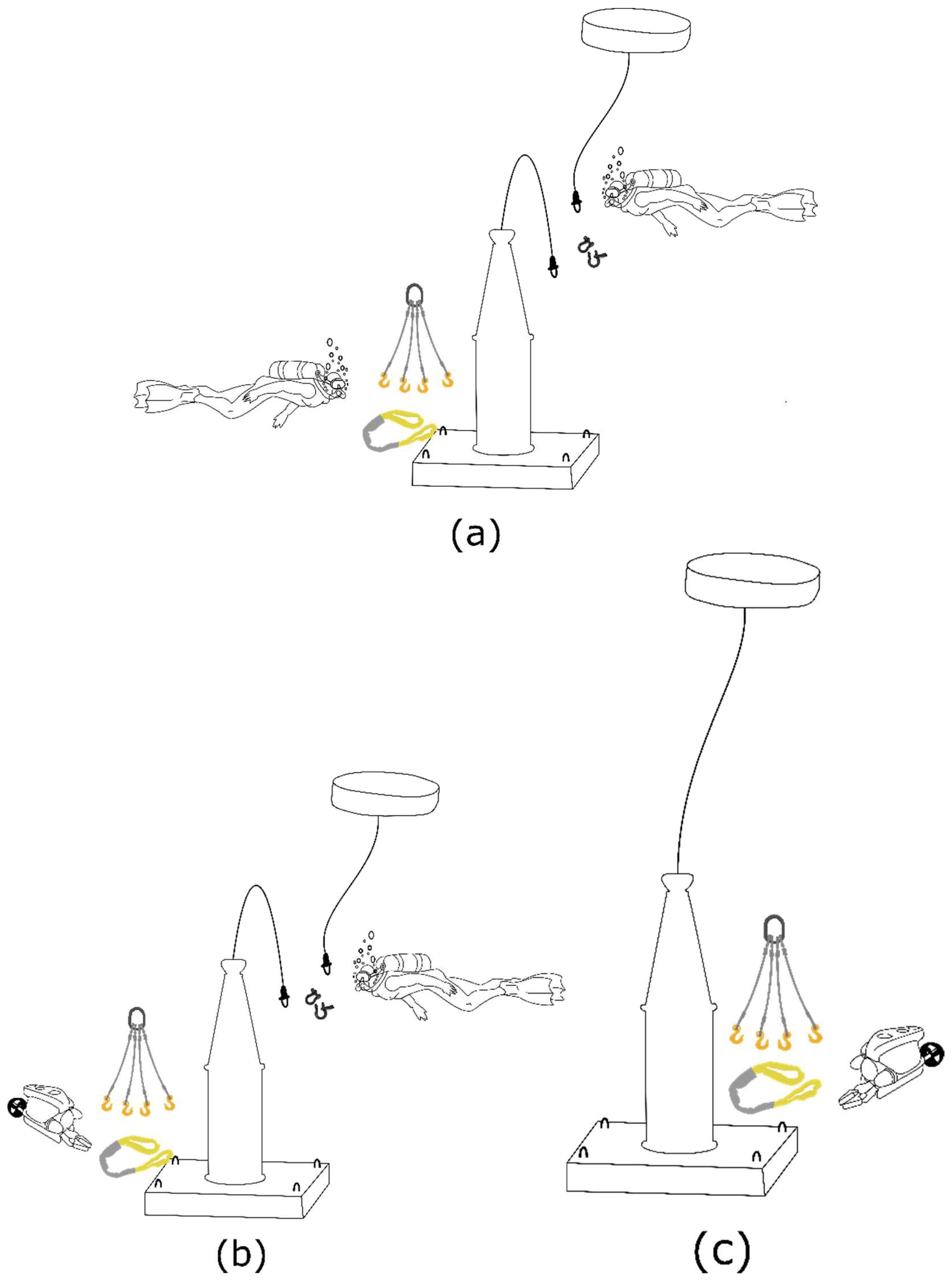
3.1. Deployment Methods

We analyze three different deployment methods, in which divers and/or ROVs participate in the submersion into water, and in buoy and cable connections of the WEC components.

3.1.1. Method 1—Wave Energy Convertors (WEC) and Buoy Deployment Separately (Work Done by Divers Only)

In the first method (Figure 5a) the buoy is deployed subsequently from its generator. The generator is first lowered to the seabed with a crane while being pressurized [40]. A diver removes the lifting slings and shackles, closes the pressurization valve, and pulls off the pressurization hose. Subsequently, the buoy is lowered towards the WEC, while the translator is lifted up using airbags. The connection and safety lines are attached to the buoy by a diver. This procedure is the one followed for all deployments using divers at the LRS. It is well-known and serves as a basis for a development towards robotized methods.

3.1.2. Method 2—WEC and Buoy Deployment Separately (Work Done by Divers and ROVs)

For an automated method using ROVs, the different steps from the first method need to be adapted for ROV use. However, the connection of the buoy to the generator is not feasible by a small ROV due to the weight of the translator (1 to 10 tons [7]), the precision required to lift it, and the moving buoy. It is, hence, not possible to fully automate the first procedure currently used at the LRS. Therefore, the second method (Figure 5b) combines the use of divers and ROVs, where divers carry out the buoy connection and ROVs execute the remaining operations, such as removing the lifting slings and shackles, closing the pressurization valve, and pulling off the pressurization hose.

3.1.3. Method 3—WEC and Buoy Deployed Together (Work Done by ROVs Only)

The third method (Figure 5c) is a theoretical evolution of the two first methods. It is conceived for ROV deployments, where robots are exclusively used. The submersion of the WEC is done with the help of two cranes. The generator is slowly submerged into the water with the first crane. Parallel to the submersion process, the other crane brings the buoy to the water. The disconnections of the slings, shackles, and pressurization hose are performed by ROVs.
All three methods have advantages and disadvantages. The vulnerability of the first and second method lies in the lifting of the translator that must not hit the stator while it is moving up, taking into account its weight and the buoy in motion at the water surface. The third method uses two cranes simultaneously which is an even more sensitive operation with additional higher costs because of a greater use of more equipment and longer preparation times. The three methods are schematized in Figure 5 and summarized in Table 2.
Concerning the connection phase, the connectors used in the LRS are dry connectors requiring a dry environment to be mated. The solution is to encapsulate the connectors on the MS in “air-pockets” [41,42]. Those pockets are filled with air when a connection is performed and, hence, create a dry environment under water. The cables can be connected at lower costs but the procedure becomes more complex. In the case of a diver-conducted operation the diver needs to both hold the cable while inserting air in the pocket, take the dummies off its cable, and hold the air hose while mating the connectors. In case of a ROV-conducted operation, two ROVs are necessary for the cable connection, where one is used to insert the air while the other performs the mating.
In all methods the buoy and generator preparation is done by three workers. The first method was chosen for analysis because it has been tested by UU, while the other two have been partially tested and are proposed as optimizations.

3.2. Monitoring and Maintenance Operations

Monitoring at the LRS is carried out annually and the operations typically take between half and a full day, depending on the type of boat, crew experience, and weather. A typical error diagnostic is conducted from a small boat, with a dive crew and two workers examining the cable. A stable boat helps in lifting the cable and accelerates the procedure. A different procedure applies when monitoring the power cable. The cable is heavy (6 kg/m) and requires a winch for lifting. The need for a large boat and a larger crew increases the maintenance cost and time.
Other reasons for maintenance concern connection lines and connection parts, like shackles between the buoy and the funnel of the WEC, where the maintenance consists in connecting a shackle or a line replacement. This task requires high precision (unscrewing the shackle, replacing it, working on a moving body), which is hardly done by ROVs. Therefore, it will not be taken into account in this study. Cable monitoring will be considered alone.

3.2.1. ROV-Assisted Monitoring

For monitoring purposes, the ROV should be small and maneuverable in order to enable the examination of any parts of the WEC. In O&G industry-specific AUVs and ROVs were developed for observation and, more specifically, for pipeline cracks and moorings [37,43,44,45]. For a point-absorbing WEC the examination would require a basic observation-class ROV with a camera system. Today’s research is focused on collaborative inspections with multiple ROVs working together on the observation of several devices [46,47]. This possibility would substantially reduce the operation duration and costs.

3.2.2. Diving-Assisted Monitoring

When employing divers for monitoring tasks the need for a crew of at least three trained and certified persons is always necessary. If the water is shallower than 30 m and the task mainly concerns lightweight work or observation, an S30 certificate is sufficient. The operation can be carried out using SCUBA diving equipment and thereby be performed from a smaller boat. Thus, the costs remain comparably low. When employing higher-certified divers the costs do not usually depend on the conducted task, provided that no special equipment is needed. However, a critical factor for price determination is the working depth. Depth can affect the safety provisions with, for example, the need for an onboard decompression chamber, which requires a larger boat and crew. In our study, as for LRS WEC deployments, monitoring is done at a depth of 25 m.

3.3. Evaluation of Time, Safety, and Complexity of Underwater Tasks Assisted by Divers or ROVs

A study was conducted to evaluate the time, safety, and complexity of each underwater task carried out during a WEC deployment or monitoring operation. The results of this study indicate the priority level to automate a task done by divers, or to improve a method for an ROV-conducted operation. The evaluation for each method uses different factors. For a diver-assisted method, personal safety and operational time are the two evaluated factors. Those two aspects are of significant interest because they give an insight of the steps that should be primarily automated: the steps where personal safety is low, and where operational time is high. High personal safety is of general importance and interest for high risk tasks, such as diving and ought to be improved, whereas shorter operational times are of economic relevance for offshore operations.
When using a ROV-assisted method, complexity and time of operation are the two evaluated factors. Complex tasks have a large impact on ROV-conducted operations because they demand higher ROV specifications and tooling. The more complex the task, the finer the balance requirement between force and accuracy, which is not easily achieved by todays ROVs. An example of such a task is the cable connection. The force needed for mating two connectors can reach up to 200 N, and the alignment accuracy should be less than 2 mm. For such tasks, tools and methods should be primarily adapted to enable and facilitate ROV-operated actions. Operational time is, as for diver-assisted operations, of economic relevance. Although material safety is an important aspect for any ROV offshore operation [48], it is not taken into account here because the depth of work would allow a fast retrieval of the device from the seabed, in case of problems. Personal safety during ROV operations is not regarded as highly important due to no direct personal involvement during the task.
In Table 3, a 1 to 5 evaluation scale is presented and further used in Table 4, where personal safety and time are evaluated for diver-assisted operations, and complexity and time for ROV-conducted operations, on the above scale. The findings of this study are presented in Table 4. The scale is represented by numbers from 1 to 5, as suggested in Table 3, where the lower the number, the quicker, safer, and simpler the task is. As the numbers grow, the safety and simplicity of the procedure lowers, while the procedure itself becomes more time-consuming. The resulting color indicates the priority level to automate each task in the case of a diver-assisted method, or to improve the operation procedure for a ROV-conducted method. The priority levels are a result of the operational time × personal safety for a diver-assisted method, and of the operational time × task complexity for a ROV-conducted method. The final product (the priority levels) is measured from 1 to 25, complying to a color code—green, yellow, and red—as seen in Table 4.
The logic behind the numbering is that as the numbers increase, the need for automation and improvement increase, too. Similarly, the color coding reflects the need for improvement and automation of tasks to make them safer. Since green is generally representative of low risk, it matches with the lower numbers (1 to 4); yellow, which represents medium risks, characterizes numbers 5 to 12; and, finally, red, indicative of high risks, symbolizes numbers 13 to 25.

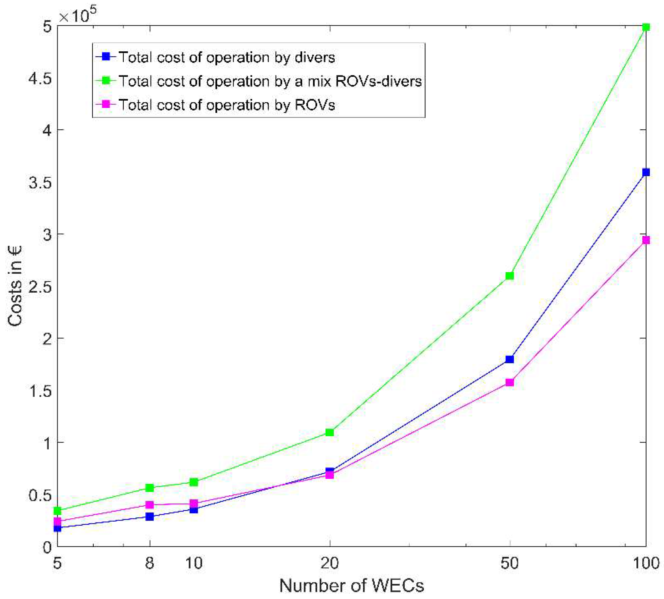
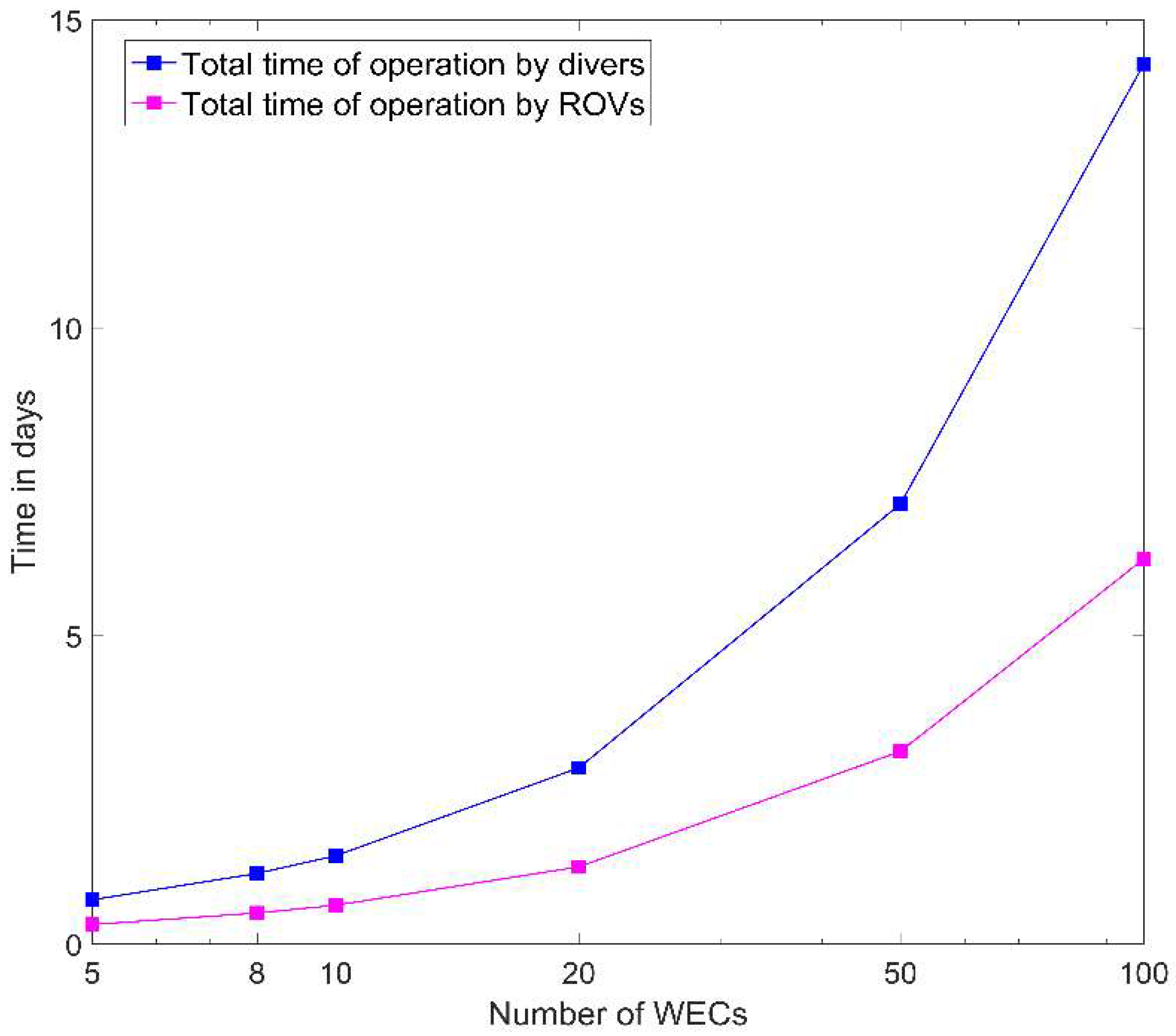
3.4. Comparative Study on Time and Cost of Operations

Below we compare the time and cost of operation for divers and ROVs for each phase of a WEC deployment, depending on the number of WECs to be installed and the deployment method. The time and costs reflect ideal conditions where no issues occur during the operation. No margins nor errors were taken into account because delays due to troubleshooting of underwater activities are unpredictable and would not be representative of reality. Results are shown in Table 5 and Table 6.
Based on Table 5 and Table 6, the following formulas are deduced for the total time of deployment, in hours, and the costs of deployment in €. The total deployment time is divided into the different steps’ duration for each method. The cost calculation uses a working day of 8 h, and allowing a diver crew 3.5 h of diving and a maximum of seven dives per day.
Time Deployment ( method   1 , 2 , 3 ,   in   hours ) = A ( B + C ) Generator   deployment + A ( D + E ) Buoy   deployment + A F Cable   connection
Time Monitoring ( method   1 ,   in   days ) = A G 3.5 Device   monitoring
Time Monitoring ( method   3 ,   in   days ) = A G 8 Device   monitoring
Costs Deployment ( method   1 ) = A ( B + D ) 3 P worker preparation + A ( C + E + F ) 8 3.5 ( 4 P diver + P boat ) underwater   work  
Costs Deployment ( method   2 ) = A ( B + D ) 3 P worker preparation + A E 8 3.5 ( 4 P diver + P boat ) Underwater   diver   work + ( floor ( A C 8 ) + 1 ) P ROV   Pro Underwater   work   using   1   ROV + ( floor ( A F 8 ) + 1 ) ( P ROV   Pro + P ROV   Def ) Underwater   work   using   2   ROVs + A ( C + F ) P boat Boat   for   ROVs
Costs Deployment ( method   3 ) = A ( B + D ) 3 P worker preparation + A ( floor ( C 8 ) + 1 ) P ROV   Pro Underwater   work   using   1   ROV + A ( floor ( A F 8 ) + 1 ) ( P ROV   Pro + P ROV   Def ) Underwater   work   using   2   ROVs + A ( C + F ) P boat Boat   for   ROVs
Costs Monitoring ( method   1 ) = A G 8 3.5 ( 4 P diver + P boat )
Costs Monitoring ( method   3 ) = ( floor ( A G 8 ) + 1 ) P ROV   Monitoring + A G P boat

4. Results and Discussion
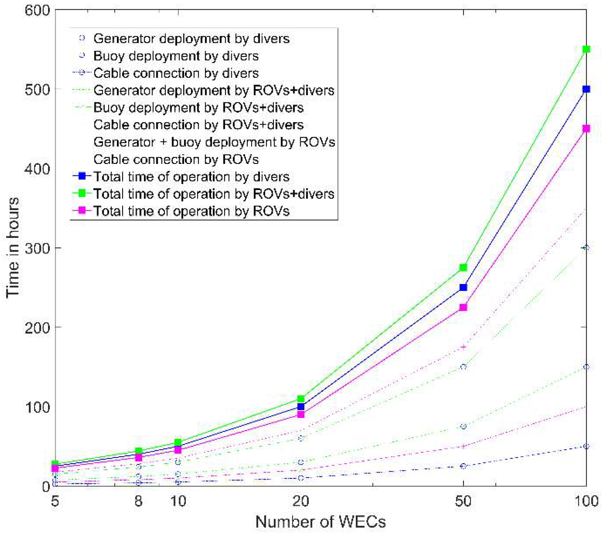
4.1. Deployment

Estimations and comparisons of deployment time for a number of WECs ranging from 5 to 100 are presented in Figure 6, and show that the method using ROVs seem to be the best compared to the other methods. The deployment method using ROVs contains indeed only two steps, while divers have to go through three steps, of which one (the buoy connection) is rather long and challenging (2 h of underwater work). This indicates that it might be disadvantageous to use divers. The challenge of lifting the translator, which adds substantial time to the buoy connection step, could be shortened with the help of specialized lifting tools. This will make the use of divers, or both divers and ROVs, as advantageous as employing only ROVs. The total time for Method 2 is greater than for both Methods 1 and 3, by approximately 9% and 23%, respectively. However, it should be underlined that divers are limited in number and the duration of dives. In our case, for a working depth at 25 m, the approximate dive time per day for a four-diver team is 3.5 h for seven dives, which considerably limits the work during an 8 h working day. Thus, Method 2 combines advantages of Methods 1 and 3. Finally, deploying five WECs takes approximately the same time for all three methods (6% difference in time). Since Method 1 requires less equipment (one crane mounted on the barge) it is a suitable alternative to a fully-robotized deployment.
In terms of costs, the results presented in Figure 7 show that Method 1 is effective for maximum fifteen WECs, while Method 3 becomes advantageous with the increasing number of WECs to be deployed. The main reason is the cable connection step, for which Method 3 requires two ROVs and 0.5 h per WEC in contrast to one dive of 0.5 h per WEC for Method 1. For one to five WECs, the ROV’s operational time takes less than one day, but since ROVs are rented for one day at least, the cost of the cable connection phase in Method 3 will never go below this fixed price. For a larger number of WECs, ROVs are utilized more efficiently since a greater number of cable connections is carried out. Yet, the cable connection cost could be reduced by a factor of two if special connection tools were developed so that only one vehicle is needed. UU has also been involved in the development of this phase so that it would be efficiently performed by ROVs in terms of time and material. A specific gripper, with two claws, would allow the connectors to be directly aligned with each other before mating [42], as a docking system for ROVs would substantially help the vehicle stabilize around the connection point and serve as a support plate for the mating that requires high forces [49,50].
Overall, it can be clearly seen from Figure 6 and Figure 7 that using ROVs (Methods 2 and 3) is advantageous compared to divers (Method 1), especially for large deployments. However, to this day, few ROVs are utilized for wave and tidal energy conversion technologies as the ROV market is still only under development. To the authors’ knowledge, there are few worldwide conferences exclusively and mainly focused on underwater robotics (for example, IFAC CAMS, WASET, Underwater Intervention and Apca Controlo). Around 1000 ROVs are produced every year, which are few in comparison to the number of offshore renewable energy plants installed in the world. Another reason is the lack of tools and equipment for assisting ROVs in their tasks. Developments that would be most beneficial to WEC deployment are: docking systems, specific grippers and manipulators, drums for cable dragging, automatic shackles for ROV use, and electrical connectors for ROV use [51]. One final reason is the need for trained personnel to operate and maintain the ROV and its instruments. To this day, ROV control lacks affordable and accurate positioning systems providing reliable data to an autopilot or a maneuver aid for the operator [52]. This prevents less-trained people from acquiring low-cost vehicles. However, considerable work is currently devoted in developing and improving ROV control systems [53] through, for example, vision and image processing [54,55,56], more compact, less energy consuming, and accurate positioning tools [47,57,58,59], or more advanced and optimized algorithms that can be processed by smaller computers [60,61].

4.2. Monitoring

Monitoring tasks occur during the deployment phase for the submersion process and after the deployment on an annual basis for sea cables and connection parts of the WEC, such as shackles and connection lines. Figure 8 and Figure 9 present a comparison of time and costs for the use of divers and ROVs for the monitoring phase. Both figures show similar patterns. The monitoring of a WEC using autonomous robots has numerous benefits compared to divers. First, a small vehicle can navigate to inaccessible areas. Second, the costs are comparatively lower. Such a task is repetitive and easy to be carried out autonomously. Moreover, the divers, being limited in the number of dives, the monitoring costs quickly diverge between the two methods despite an operation time of 0.5 h per WEC for both.

4.3. Purchasing Versus Renting a ROV

Presented results of total costs and time are lower for monitoring purposes using ROVs compared to divers. Together with the growing offshore renewable energy sector, the fundamental question of hiring or purchasing ROVs arise. In the case of purchasing a ROV, the costs should include one personnel that can maneuver and maintain the ROV. Table 7 shows two typical ROVs that could be used for the different tasks required in a WEC deployment and monitoring. Purchasing an ROV, the break-even comes after 25 and 23 working days, respectively, depending on the chosen vehicle. For a wave power plant of ten converters, two days of underwater work are needed for the deployment and one day per year for monitoring. The ROV is, hence, fully refunded after 23 and 21 years, respectively. For a plant of 100 WECs, the underwater work takes 19 days, and the monitoring 10 days per year. Hence, the return on investment is less than two years, which should be compared to the expected life time of 25 years for a wave power park.

4.4. Adapting Processes from the Offshore Wind Field of Application

As offshore wind power plants are increasing in numbers, processes associated to the deployment and monitoring of their devices are being automated. In monitoring procedures ROVs are extensively used for seabed and structure inspections [62], launching and retrieving of measurement packages, plankton sampling, and in situ monitoring [63], which means that such ROVs are available for similar operations on WECs. The deployment and decommissioning of wind energy devices also presents similarities with wave energy in the use of ROVs. In [62], underwater vehicles are used for the installation of lifting attachments on structures such as foundations, jackets, or monopiles. They could easily be replicated and adapted for the commissioning of WECs, which show identical needs. Operations related to electrical cables are also typically similar. The offshore wind energy sector makes great use of ROVs for laying, trenching, dragging, and localizing cables, both for inner-array and from park to shore [62,64,65,66]. All operations related to cables can be applied to the wave energy field. Concerning cable connections, the challenges can differ, as offshore wind power devices usually have their electrical couplings located above the water level. Turbines are placed on top of the masts and substations are usually settled at the water surface so there is no need for ROVs to perform the connections. Finally, [67] values the use of ROVs in shallow water operations, where large vessels are not exploitable. At those depths ROVs are a valuable means of support for any offshore renewable energy conversion technology deployment.

5. Conclusions

This paper is intended to serve as a guidance in future offshore operations with a focus on automation in WEC deployments. It gives an insight into the technical challenges to address in order to face future progress of wave energy technologies. It also shows the potential time and costs saved when using ROVs instead of divers in underwater operations.
For the deployment of WECs, in Sweden at a depth of 25 m, the use of ROVs is theoretically less time-consuming than the use of divers, and of lower cost when deploying more than seven WECs at a time. Deploying five WECs takes approximately the same time for all three methods (6% difference in time). The expenses decrease to one third for the deployment of 20 WECs using ROVs compared to divers. However, the lack of affordable and easily-maneuverable middle-class ROVs, and especially the lack of tools for assisting the ROV in its task, make them seldom used in reality. The development of the following equipment would simplify the deployment and monitoring of WECs using automated methods: ROV-friendly shackles and slings, electrical connectors, docking systems, specific grippers for cable connection, and ROV drums for cable dragging. For depths of more than 30 m, the costs of hiring divers can triple, and the personal safety decreases with the dive time and depth. Although there is a broad availability of ROVs for deep-water operations, their use in shallower water is not as widespread. There is a greater need to focus on developing the tooling, accuracy, and mobility of ROVs than their working depth. Method 1 is the most cost efficient for a maximum of five WECs, and Method 3 is preferable as the number of WECs to be deployed increases.
Using divers, the deployment could become faster with the help of a specially-designed system for lifting the translator. Generally, for large deployments, Methods 2 and 3 (using ROVs) are more suitable than Method 1 (employing divers), although a small number of ROVs is utilized for the offshore renewable energy conversion technologies sector.
The monitoring of WECs and their electrical cables is done more easily and with lower costs by ROVs. ROVs can access remote areas and perform long and repetitive tasks. Monitoring, with the use of ROVs, requires a well-trained and skilled operator, compared to divers who are able to perform tasks with better manual dexterity, but improvements of the ROVs in terms of accurate positioning and maneuverability gradually allow more and more people to acquire and easily operate an ROV.
The choice of acquiring an ROV, instead of renting it, depends on the size of the power plant. For example the breakeven of a 20 WEC park is around 10 years for the purchase of a VideoRay Defender, and decreases with the growth of the park’s size. For a plant of 100 WECs, the return on investment is less than two years, which, compared to the expected life time of 25 years for a wave power park, is beneficial.
Automation is an essential step in the industrialization of offshore renewable energy conversion technologies and the wave energy sector has much to learn from offshore wind applications, where the use of ROVs progressively grows. In monitoring operations underwater vehicles are widely used for visual inspections, sampling, installation, and retrieving of sensor packages. During deployments ROVs are mostly used for electrical cable commissioning operations, and lifting attachment installation. It would be easy to adapt those solutions to wave energy applications.
The methodology/modelling presented in this paper is generalized for most types of wave energy technologies, since it does not depend on the structure size or type. Its main parameters are typical: the number of generators to be deployed, preparation and submersion time by divers and ROVs, connection time of buoys and cables done by divers/ROVs, and labor costs of divers or renting costs for ROVs. Most types of converters (point absorbers, oscillating water columns), besides attenuators, could comply with this model, proving a broad utilization of the present methodology, since the connection and disconnection of the slings, shackles, and cable connections applies to all. Lastly, the lifting of the WEC depends on the type, but it should be common among the point absorbers and oscillating water columns.

Acknowledgments

This research was supported by StandUp for Energy, the OceaNET project, which has received funding from the European Union’s Seventh Framework Programme for research, technological development, and demonstration under grant agreement no. 607656, the Swedish Energy Agency, and Uppsala University. The authors would like to thank their colleagues Liselotte Ulvgård, Francisco Francisco, Rafael Waters, and Mats Leijon for assistance with the technical details of wave energy converters developed at Uppsala University. The authors are also grateful to F. Fleetwood and M. Häggström for the valuable information they provided while writing this article.

Author Contributions

Flore Rémouit, Maria-Angeliki Chatzigiannakou, and Anke Bender collaborated together on all the parts of the paper. Their collaboration is the result of different skills in ROVs (Flore), diving (Anke), and deployments (Maria), with a common experience of the wave energy converters developed at Uppsala University, the Lysekil research site, and the different offshore operations performed there. Irina Temiz, Jan Sundberg, and Jens Engström reviewed and commented on the paper, as well as helped with language corrections.

Conflicts of Interest

The authors declare no conflict of interest. The founding sponsors had no role in the design of the study; in the collection, analyses, or interpretation of data; in the writing of the manuscript; or in the decision to publish the results.

References

  1. Lawso, J. A perfect match?: Oil and gas companies have learned to overcome many offshore difficulties, so what, if anything, can they bring to the renewable energy table? Renew. Energy Focus 2011, 12, 38–40. [Google Scholar] [CrossRef]
  2. Capocci, R.; Dooly, G.; Toal, D. Offshore renewable energy systems: Solutions for reduction in operational costs. In Proceedings of the 2017 Twelfth International Conference on Ecological Vehicles and Renewable Energies (EVER), Monte-Carlo, Monaco, 11–13 April 2017; pp. 1–8. [Google Scholar]
  3. Shukla, A.; Karki, H. Application of robotics in offshore oil and gas industry—A review Part II. Robot. Auton. Syst. 2016, 75 Pt B, 508–524. [Google Scholar] [CrossRef]
  4. Stavinoha, S.; Chen, H.; Walker, M.; Zhang, B.; Fuhlbrigge, T. Challenges of robotics and automation in offshore oil and gas industry. In Proceedings of the 4th Annual IEEE International Conference on Cyber Technology in Automation, Control and Intelligent, Hong Kong, China, 4–7 June 2014; pp. 557–562. [Google Scholar]
  5. Leijon, M.; Waters, R.; Rahm, M.; Svensson, O.; Bostrom, C.; Stromstedt, E.; Engstrom, J.; Tyrberg, S.; Savin, A.; Gravrakmo, H.; et al. Catch the wave to electricity. IEEE Power Energy Mag. 2009, 7, 50–54. [Google Scholar] [CrossRef]
  6. Lejerskog, E.; Boström, C.; Hai, L.; Waters, R.; Leijon, M. Experimental results on power absorption from a wave energy converter at the Lysekil wave energy research site. Renew. Energy 2015, 77, 9–14. [Google Scholar] [CrossRef]
  7. Parwal, A.; Remouit, F.; Hong, Y.; Francisco, F.; Castelucci, V.; Hai, L.; Ulvgård, L.; Li, W.; Lejerskog, E.; Baudoin, A.; et al. Wave Energy Research at Uppsala University and the Lysekil Research Site, Sweden: A Status Update. In Proceedings of the 11th European Wave and Tidal Energy Conference (EWTEC), Nantes, France, 6–11 September 2015. [Google Scholar]
  8. Chatzigiannakou, M.A.; Dolguntseva, I.; Leijon, M. Offshore Deployments of Wave Energy Converters by Seabased Industry AB. J. Mar. Sci. Eng. 2017, 5, 15. [Google Scholar] [CrossRef]
  9. Göteman, M.; Engström, J.; Eriksson, M.; Isberg, J. Numerical and semi-analytical methods for optimizing wave energy parks. In Proceedings of the 11th International Conference on Hydrodynamics (ICHD 2014), Singapore, 19–24 October 2014. [Google Scholar]
  10. Engström, J.; Eriksson, M.; Göteman, M.; Isberg, J.; Leijon, M. Performance of large arrays of point absorbing direct-driven wave energy converters. J. Appl. Phys. 2013, 114, 204502. [Google Scholar] [CrossRef]
  11. Hong, Y.; Eriksson, M.; Boström, C.; Waters, R. Impact of Generator Stroke Length on Energy Production for a Direct Drive Wave Energy Converter. Energies 2016, 9, 730. [Google Scholar] [CrossRef]
  12. Chatzigiannakou, M.A.; Dolguntseva, I.; Ekström, R.L.; Leijon, M. Offshore Deployment of Marine Substation in the Lysekil Research Site. Presented at the Twenty-Fifth International Ocean and Polar Engineering Conference, Kona, HI, USA, 21–26 June 2015. [Google Scholar]
  13. Ekström, R.; Baudoin, A.; Rahm, M.; Leijon, M. Marine substation design for grid-connection of a research wave power plant on the Swedish West coast. In Proceedings of the 10th European Wave and Tidal Conference (EWTEC), Aalborg, Denmark, 2–5 September 2013. [Google Scholar]
  14. Ekström, R.; Kurupath, V.; Svensson, O.; Leijon, M. Measurement system design and implementation for grid-connected marine substation. Renew. Energy 2013, 55, 338–346. [Google Scholar] [CrossRef]
  15. Rahm, M.; Bostrom, C.; Svensson, O.; Grabbe, M.; Bulow, F.; Leijon, M. Offshore underwater substation for wave energy converter arrays. IET Renew. Power Gener. 2010, 4, 602–612. [Google Scholar] [CrossRef]
  16. Cato, I.; Kjellin, B. Maringeologiska undersökningar vid vågkraft-anläggning utanför Islandsberg, Bohuslän; SGU-rapport; Sveriges Geologiska Undersökning: Sweden, Uppsala, 2008; p. 10. [Google Scholar]
  17. Lejerskog, E.; Gravråkmo, H.; Savin, A.; Strömstedt, E.; Tyrberg, S.; Haikonen, K.; Krishna, R.; Boström, C.; Rahm, M.; Ekström, R.; et al. Lysekil Research Site, Sweden: Status Update. In Proceedings of the 9th European Wave and Tidal Energy Conference (EWTEC), Southampton, UK, 5–9 September 2011. [Google Scholar]
  18. Waters, R.; Engström, J.; Isberg, J.; Leijon, M. Wave climate off the Swedish west coast. Renew. Energy 2009, 34, 1600–1606. [Google Scholar] [CrossRef]
  19. Chatzigiannakou, M.A.; Dolguntseva, I.; Leijon, M. Offshore Deployment of Point Absorbing Wave Energy Converters with a Direct Driven Linear Generator Power Take-Off at the Lysekil Test Site. In Proceedings of the SME 2014 33rd International Conference on Ocean, Offshore and Arctic Engineering, San Francisco, CA, USA, 8–13 June 2014; p. V09AT09A023. [Google Scholar]
  20. A Set-Up of 7 Laser Triangulation Sensors and a Draw-Wire Sensor for Measuring Relative Displacement of a Piston Rod Mechanical Lead-Through Transmission in an Offshore Wave Energy Converter on the Ocean Floor. Available online: https://www.hindawi.com/journals/isrn/2012/746865/ (accessed on 17 January 2018).
  21. Mueller, M.; Wallace, R. Enabling science and technology for marine renewable energy. Energy Policy 2008, 36, 4376–4382. [Google Scholar] [CrossRef]
  22. Bahaj, A. Generating electricity from the oceans. Renew. Sustain. Energy Rev. 2011, 36, 4136–4141. [Google Scholar] [CrossRef]
  23. Kelly, J.; O’Sullivan, D.; Wright, W.; Alcorn, R.; Lewis, A.W. Challenges and lessons learned in the deployment of an offshore oscillating water column. COMPEL Int. J. Comput. Math. Electr. Electron. Eng. 2014, 33, 1678–1704. [Google Scholar] [CrossRef]
  24. Henry, A.; Doherty, K.; Cameron, L.; Whittaker, T.; Doherty, R. Advances in the Design of the Oyster Wave Energy Converter. In Proceedings of the Marine Renewables and Offshore Wind Conference, Royal Institute of Naval Architects, At RINA HQ, London, UK, 21–23 April 2010. [Google Scholar]
  25. Marine Renewable Energy Technology and Environmental|Mark A. Shields|Springer. Available online: http://www.springer.com/la/book/9789401780018 (accessed on 12 December 2017).
  26. Chen, H.; Stavinoha, S.; Walker, M.; Zhang, B.; Fuhlbrigge, T. Opportunities and Challenges of Robotics and Automation in Offshore Oil & Gas Industry. Intell. Control Autom. 2014, 5, 136. [Google Scholar]
  27. Anisi, D.A.; Skourup, C. A step-wise approach to oil and gas robotics. IFAC Proc. 2012, 45, 47–52. [Google Scholar] [CrossRef]
  28. Stewart, D.J. Book Review: Maritime Archaeology: A Reader of Substantive and Theoretical Contributions edited by Lawrence E. Babits and Hans Van Tilburg. Northeast Hist. Archaeol. 1998, 27, 11. [Google Scholar] [CrossRef]
  29. Adie, W.; Cairns, J.; Macdiarmid, J.; Ross, J.; Watt, S.; Taylor, C.L.; Osman, L.M. Safety culture and accident risk control: Perceptions of professional divers and offshore workers. Saf. Sci. 2005, 43, 131–145. [Google Scholar] [CrossRef]
  30. Douglas, J.D.; Milne, A.H. Decompression sickness in fish farm workers: A new occupational hazard. BMJ 1991, 302, 1244–1245. [Google Scholar] [CrossRef] [PubMed]
  31. Myers, M.L. Review of occupational hazards associated with aquaculture. J. Agromed. 2010, 15, 412–426. [Google Scholar] [CrossRef]
  32. Adapting Offshore Wind Power Foundations to Local Environment, Naturvårdsverket. Available online: http://www.naturvardsverket.se/Om-Naturvardsverket/Publikationer/ISBN/6300/978-91-620-6367-2/ (accessed on 16 January 2018).
  33. Documents. Available online: http://www.edtc.org/Documents.htm (accessed on 6 February 2018).
  34. Dykeriarbete (AFS 2010:16), föreskrifter—Arbetsmiljöverket. Available online: https://www.av.se/arbetsmiljoarbete-och-inspektioner/publikationer/foreskrifter/dykeriarbete-afs-201016-foreskrifter/ (accessed on 16 January 2018).
  35. RMS-Dyk, Kapitel 13 Dekompressionstabeller. Available online: http://dokument.forsvarsmakten.se/RMS/rms_2013/webb/RMS_Dyk/RMS_Dyk_Kap_13/RMS_Dyk_Kap_13.htm#CIHIFHIG (accessed on 16 January 2018).
  36. Molland, A.F. (Ed.) Underwater vehicles. In The Maritime Engineering Reference Book; Butterworth-Heinemann: Oxford, UK, 2008; Chapter 10; pp. 728–783. [Google Scholar]
  37. Wynn, R.B.; Huvenne, V.A.; Le Bas, T.P.; Murton, B.J.; Connelly, D.P.; Bett, B.J.; Ruhl, H.A.; Morris, K.J.; Peakall, J.; Parsons, D.R.; et al. Autonomous Underwater Vehicles (AUVs): Their past, present and future contributions to the advancement of marine geoscience. Mar. Geol. 2014, 352, 451–468. [Google Scholar] [CrossRef] [Green Version]
  38. Christ, R.D.; Sr, R.L.W. The ROV Manual, a User Guide for Remotely-Operated Vehicles, 2nd ed.; Butterworth-Heinemann: Amsterdam, The Netherlands, 2013. [Google Scholar]
  39. Capocci, R.; Dooly, G.; Omerdić, E.; Coleman, J.; Newe, T.; Toal, D. Inspection-Class Remotely-operated vehicles—A Review. J. Mar. Sci. Eng. 2017, 5, 13. [Google Scholar] [CrossRef]
  40. Chatzigiannakou, M.A.; Ulvgård, L.; Dolguntseva, I.; Leijon, M. Offshore Deployments of Wave Energy Converters by Uppsala University. Mar. Syst. Ocean Technol. 2018. submitted. [Google Scholar]
  41. Remouit, F. Underwater Electrical Connections and Remotely-Operated Vehicles. Licenciate Thesis, Uppsala University, Uppsala, Sweden, 2016. [Google Scholar]
  42. Remouit, F.; Lopes, M.F.; Pires, P.; Sebastiao, L.; Rahm, M. Automation of Subsea Connection for Clusters of Wave Energy Converters. In Proceedings of the 26th Conference ISOPE, Kona, HI, USA, 21–26 June 2016; Available online: https://www.researchgate.net/publication/283552145_Automation_of_subsea_connection_for_clusters_of_wave_energy_converters (accessed on 12 December 2017).
  43. Pacunski, R.; Palsson, W.; Greene, H.; Gunderson, D. Conducting Visual Surveys with a Small ROV in Shallow Water. In Marine Habitat Mapping Technology for Alaska; Reynolds, J.R., Greene, H.G., Eds.; University of Alaska Fairbanks: Alaska, AK, USA, 2008. [Google Scholar] [CrossRef]
  44. Ajemian, M.J.; Wetz, J.J.; Shipley-Lozano, B.; Stunz, G.W. Rapid assessment of fish communities on submerged oil and gas platform reefs using remotely-operated vehicles. Fish. Res. 2015, 167, 143–155. [Google Scholar] [CrossRef]
  45. Kato, N.; Choyekh, M.; Dewantara, R.; Senga, H.; Chiba, H.; Kobayashi, E.; Yoshie, M.; Tanaka, T.; Short, T. An autonomous underwater robot for tracking and monitoring of subsea plumes after oil spills and gas leaks from seafloor. J. Loss Prev. Process Ind. 2017, 50, 386–396. [Google Scholar] [CrossRef]
  46. Christensen, D.J.; Andersen, J.C.; Blanke, M.; Furno, L.; Galeazzi, R.; Hansen, P.N.; Nielsen, M.C. Collective Modular Underwater Robotic System for Long-Term Autonomous Operation. Science 2014, 19, 35–40. [Google Scholar]
  47. Djapic, V.; Dong, W.; Spaccini, D.; Cario, G.; Casavola, A.; Gjanci, P.; Lupia, M.; Petrioli, C. Cooperation of coordinated teams of Autonomous Underwater Vehicles. IFAC-PapersOnLine 2016, 49, 88–93. [Google Scholar] [CrossRef]
  48. Vedachalam, N.; Ramesh, R.; Jyothi, V.B.N.; Ramadass, G.A.; Atmanand, M.A. An approach to operational risk modeling and estimation of safety levels for deep water work class remotely operated vehicle—A case study with reference to ROSUB 6000. J. Ocean Eng. Sci. 2016, 1, 109–118. [Google Scholar] [CrossRef]
  49. Remouit, F.; Abrahamsson, J.; Engström, J. Optical System for Underwater Positioning of Observation Class Remotely Operated Vehicle. Presented at the 3rd Asian Wave and Tidal Energy Conference (AWTEC), Singapore, Singapore, 24–28 October 2016. [Google Scholar]
  50. Li, D.; Chen, Y.; Shi, J.; Yang, C. Autonomous underwater vehicle docking system for cabled ocean observatory network. Ocean Eng. 2015, 109, 127–134. [Google Scholar] [CrossRef]
  51. Rémouit, F.; Ruiz-Minguela, P.; Engström, J. Review of Electrical Connectors for Underwater Applications. IEEE J. Ocean. Eng. 2017, 1–11. [Google Scholar] [CrossRef]
  52. Paull, L.; Saeedi, S.; Seto, M.; Li, H. AUV Navigation and Localization: A Review. IEEE J. Ocean. Eng. 2014, 39, 131–149. [Google Scholar] [CrossRef]
  53. Stewart, A.; Ryden, F.; Cox, R. An interactive interface for multi-pilot ROV intervention. In Proceedings of the OCEANS 2016, Shanghai, China, 10–13 April 2016; pp. 1–6. [Google Scholar]
  54. Li, Y.; Zhang, Y.; Xu, X.; He, L.; Serikawa, S.; Kim, H. Dust removal from high turbid underwater images using convolutional neural networks. Opt. Laser Technol. 2017, in press. [Google Scholar] [CrossRef]
  55. Quevedo, E.; Delory, E.; Callicó, G.M.; Tobajas, F.; Sarmiento, R. Underwater video enhancement using multi-camera super-resolution. Opt. Commun. 2017, 404, 94–102. [Google Scholar] [CrossRef]
  56. Chen, H.-H.; Chuang, W.-N.; Wang, C.-C. Vision-based line detection for underwater inspection of breakwater construction using an ROV. Ocean Eng. 2015, 109, 20–33. [Google Scholar] [CrossRef]
  57. Reis, J.; Morgado, M.; Batista, P.; Oliveira, P.; Silvestre, C. Design and Experimental Validation of a USBL Underwater Acoustic Positioning System. Sensors 2016, 16, 1491. [Google Scholar] [CrossRef] [PubMed]
  58. Wang, J.; Shi, W.; Xu, L.; Zhou, L.; Niu, Q.; Liu, J. Design of optical-acoustic hybrid underwater wireless sensor network. J. Netw. Comput. Appl. 2017, 92, 59–67. [Google Scholar] [CrossRef]
  59. Gao, X.; Zhang, F.; Ito, M. New acoustic positioning system for an underwater robot using multiple frequencies. Artif. Life Robot. 2012, 16, 542–545. [Google Scholar] [CrossRef]
  60. Gao, J.; Proctor, A.; Bradley, C. Adaptive neural network visual servo control for dynamic positioning of underwater vehicles. Neurocomputing 2015, 167, 604–613. [Google Scholar] [CrossRef]
  61. Thomson, D.; Dosso, S. AUV localization in an underwater acoustic positioning system. In Proceedings of the 2013 MTS/IEEE OCEANS, Bergen, Norway, 10–13 June 2013; pp. 1–6. [Google Scholar]
  62. Topham, E.; McMillan, D. Sustainable decommissioning of an offshore wind farm. Renew. Energy 2017, 102, 470–480. [Google Scholar] [CrossRef]
  63. Wang, P.; Tian, X.; Peng, T.; Luo, Y. A review of the state-of-the-art developments in the field monitoring of offshore structures. Ocean Eng. 2018, 147, 148–164. [Google Scholar] [CrossRef]
  64. Barlow, E.; Öztürk, D.T.; Revie, M.; Boulougouris, E.; Day, A.H.; Akartunalı, K. Exploring the impact of innovative developments to the installation process for an offshore wind farm. Ocean Eng. 2015, 109, 623–634. [Google Scholar] [CrossRef] [Green Version]
  65. Irawan, C.A.; Jones, D.; Ouelhadj, D. Bi-objective optimisation model for installation scheduling in offshore wind farms. Comput. Oper. Res. 2017, 78, 393–407. [Google Scholar] [CrossRef] [Green Version]
  66. Kaiser, M.J.; Snyder, B.F. Modeling offshore wind installation costs on the U.S. Outer Continental Shelf. Renew. Energy 2013, 50, 676–691. [Google Scholar] [CrossRef]
  67. Snyder, B.; Kaiser, M.J. Ecological and economic cost-benefit analysis of offshore wind energy. Renew. Energy 2009, 34, 1567–1578. [Google Scholar] [CrossRef]
Figure 1. (a) The linear wave energy converter and (b) marine substation developed at Uppsala University.
Jmse 06 00039 g001
Figure 2. (a) The Lysekil Research Site on the Swedish west coast, about 100 km north from Gothenburg; and (b) the Lysekil wave climate matrix.
Jmse 06 00039 g002
Figure 3. (a) Commercial pictures of the VideoRay Pro 4 and (b) Ocean Modules V8 Sii.
Jmse 06 00039 g003
Figure 4. Odyssey’s eight ton remotely-operated vehicle, called ZEUS.
Jmse 06 00039 g004
Figure 5. Schematic of the three deployment methods with (a) work done by divers only, (b) work done by both divers and ROVs, and (c) work done by ROVs only.
Jmse 06 00039 g005
Figure 6. Operational time comparison between the three deployment methods and steps for a number of WECs ranging from 5 to 100: using divers alone (Method 1), divers and ROVs (Method 2), and ROVs alone (Method 3).
Jmse 06 00039 g006
Figure 7. Operational cost comparison between the three deployment methods for a number of WECs ranging from 5 to 100: using divers alone (Method 1), divers and ROVs (Method 2), and ROVs alone (Method 3).
Jmse 06 00039 g007
Figure 8. Net time comparison for the WECs monitoring for a number of WECs ranging from 5 to 100 carried out by divers and ROVs.
Jmse 06 00039 g008
Figure 9. Cost comparison in € for the WEC monitoring for a number of WECs ranging from 5 to 100 carried out by divers and ROVs.
Jmse 06 00039 g009
Table 1. List of remotely operated vehicle (ROV) manufacturers and their products suitable for the UU wave energy convertor (WEC) deployment and monitoring.
ROV ManufacturerRecommended ROVPurchase Quote (k€)Comments
MariscopeCommander MK II140–175Medium class, instruments to be added
Ocean ModulesOcean Modules V8Sii150Medium class, includes a manipulator
SAAB SeaeyeCougar XT190Compact working class, includes a manipulator
Deep Ocean Exploration and Research (DOER)H2000340Ultra-compact work class ROV, includes a manipulator
Seamor MarineChinook210Medium class with manipulator
VideoRayPro 450Ultra-compact observation class ROV, without tool
VideoRayDefender150Ultra-compact medium class, includes a manipulator
Table 2. Presentation of the three methods: operational particularities and properties (benefits and risks).
MethodsParticularitiesBenefitsRisks
1 -WEC and buoy deployed separately
-Work done by divers only
Generator and buoy deployed separately with a crane, buoy connected to the submerged WEC at the siteWell-known and tested method, commonly usedThe use of divers jeopardizes their personal safety
2 -WEC and buoy deployed separately
-Work done by both divers and ROVs
Generator and buoy deployed separately with a crane.
Buoy connection to the submerged WEC at the site.
The buoy connection is done by divers while the other tasks are performed by ROVs
Suggested method, partially tested, middle step towards a fully- automated deploymentThe use of both divers and ROVs can raise the cost and be time consuming
3 -WEC and buoy deployed together
-Work done by ROVs only
Generator and buoy carried to the site together and deployed by two cranes at the same time.
No buoy connection step in this method
Suggested method, partially tested, fully automated deploymentNeeds precise preparation and organization, firm fastening of all lines and hoses
Table 3. Scale for evaluation of personal safety for divers- and operation complexity for ROV-conducted operations.
ScaleOperational TimePersonal SafetyComplexity of Operation
1<5 minEntirely safeVery simple procedure, repetitive and simple task
2>5 min and <15 minVery low chances of injuryMono-action operation with very low chances of sudden troubleshooting
3>15 min and <30 minMinor chances of injuryMono-action operation with minor chances of sudden troubleshooting
4>30 min and <1 hNot safeComplex operation involving multiple actions or high thrust and high accuracy
5>1 hLife threateningVery complex operation requiring high thrust, high accuracy, and multiple actions
Table 4. Evaluation of different deployment and monitoring tasks for divers and ROVs. Scaling is taken from Table 3. The multiplication of the operational time by the personal safety, or the task complexity, gives the priority level result. Level 1 to 4: The task is efficient as it is, Level 5 to 12: The task could be improved with special additional tooling/under certain circumstances; and Level 13 to 25: The task needs to be automated or improved.
PhaseTaskDiversROVs
Operational TimePersonal SafetyPriority LevelOperational TimeTask ComplexityPriority Level
WEC deploymentMonitoring of the submersion process248212
Pressurization hose disconnection133122
Disconnecting the slings and shackles2244416
Cable connectionDrag the cable to the MS5315111
Filling of air in the connector pocket/chamber224122
Underwater cable connection133133
Buoy deploymentLifting the translator34123515
Attaching the buoy34124520
MonitoringCable inspection5210515
Buoy monitoring3393515
WEC observation326313
Table 5. WEC deployment expenses with divers and ROV assistance.
SymbolResourceCost
P diver Diver90 €/h
P worker Worker for device preparation50 €/h
P boat Boat (for ROV or diver)120 €/h
P ROV   Pro VideoRay Pro 4 with cutter and gripper7000 €/day
P ROV   Def VideoRay Defender7000 €/day
P ROV   Monitoring VideoRay Pro 4 alone2000 €/day
Table 6. Time duration in hours for each step of a WEC deployment with divers and ROV assistance.
SymbolRubricTime per WEC Using Method 1 (h)Time per WEC Using Method 2 (h)Time per WEC Using Method 3 (h)
ANumber of WECs
BWEC preparation111.5
CWEC submersion0.50.50.5
DBuoy preparation111.5
EBuoy connection33
FCable connection0.511
GMonitoring0.50.5
Table 7. Costs for purchasing and renting two suitable ROVs for WEC deployment and monitoring, and break-even time.
ROVPurchase Rates (€)AbilitiesRental Rates (€/day)Break Even (In Days of Operation, Counting the Personnel)
Videoray Pro 4 Standard with 100 m cable and manipulator50,000 excl. VATDisconnect slings, remove shackles, holding the pressurized air hose for electrical connection2000 for observation
7000 for operations
From 7 to 25 days
Videoray Defender with 400 m cable and rotating manipulator150,000 excl. VATGenerator deployment, holding the pressurized air hose for electrical connection, performing a connection7000 for operations23 days

