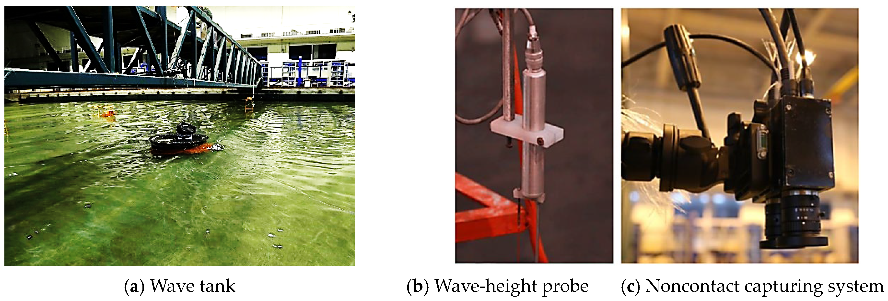
Article

Slamming Characteristics Due to the Special Shape of New Sandglass-Type Model in Waves by Comparing with Cylindrical Model

1
School of Naval Architecture, Dalian University of Technology, Dalian 116024, China
2
Dalian Shipbuilding Industry Co., Ltd., Dalian 116021, China
*
Authors to whom correspondence should be addressed.
J. Mar. Sci. Eng. 2024, 12(5), 712; https://doi.org/10.3390/jmse12050712
Submission received: 21 March 2024 / Revised: 15 April 2024 / Accepted: 23 April 2024 / Published: 25 April 2024

Abstract

:
For the new sandglass-type FPSO, the unique shape of its floating body with oblique side and external expansion can significantly improve the motion performance, but meanwhile may result in specific slamming characteristics in waves. On this basis, this paper establishes a CFD method including numerical wave-tank technique based on the Open FOAM platform. Therein, the velocity-inlet boundary method and the active absorption method are applied for numerical wave-making and wave-absorption. Compared with experimental results, the numerical method can be validated to be accurate enough to simulate wave slamming on floating ocean platforms. Then, the specific slamming phenomena on the sandglass-type floating body under a classic long wave can be investigated by comparing with the cylindrical model, including nonlinear wave rollover and breaking, water cushion, rooster-tail wave, side wave, water tongue, and so on. The mechanism of these phenomena and their effects on slamming pressure are studied. The essences of typical peaks in the time-history curve of the slamming pressure are mainly discussed. More interestingly, the main peak can be found to be related to the small peak due the amount of the broken water and the thickness of the water cushion. Finally, the slamming characteristics of the sandglass-type model in a classic short-wave condition are comparatively discussed.

1. Introduction

With the advancement of offshore oil and gas exploitation, the deep sea is garnering increasing interest. Along with further distance and harsher environment, the deep sea has more restrictions on exploitation equipment. In this context, a floating production, storage, and offloading unit (FPSO) plays a crucial role due to its integrated functions, large oil capacity, and ease of maintenance [1,2,3,4,5]. Traditional FPSO has a ship-type shape, and thus its large longitudinal scale brings to several limitations [6], such as extreme sensitivity to the wave direction, poor roll motion performance in oblique waves, etc. These limitations may not only worsen the working environment but also increase the cost of repair and maintenance. As a solution, the cylindrical FPSO was introduced to address these issues by reducing longitudinal scale and eliminating asymmetry. However, the natural period of heave motion of the cylindrical floating body is still in the centralized area of wave energy, and thus its heave motion response is quite large [7]. To overcome the shortcomings of the ship-type and cylindrical FPSOs, a new concept of FPSO with an innovative sandglass-type floating body was proposed by Wang et al. [8] and Huang et al. [9]. The sandglass-type shape design shifts brings the heave natural frequency away from the frequency range of concentration wave energy, which can effectively improve the heave performance. In addition, its sandglass-type shape with large bottom and oblique side can obviously increase the added mass and damping of pitch motion, which can also enhance the pitch performance.
For the sandglass-type FPSO, although the new shape can improve the motion performance in waves, its distinctive shape with oblique side and external expansion will cause large-area flare, which may result in specific slamming problems, possibly affecting structural safety. The slamming event is mostly characterized by nonlinear flow phenomenon and large impulsive pressures that are considerably distributed in time and space [10]. The pressure peak with a short duration is governed by the inertial effects induced by the strong acceleration of the liquid hitting the wall. The related pressure peak is strongly affected by the local flow during wave slamming [11].
In studies about the slamming of FPSOs in waves, local structural damage due to the large slamming loads has been reported [12,13,14,15]. The MV Estonia disaster of 1994, one of the most lethal marine catastrophes of the 20th century, was triggered by the bow door’s failure due to intense slamming [16]. The examples demonstrate the necessity of accurately evaluating slamming pressures and their resulting structural responses throughout the FPSO design process.
Currently, research on slamming issues for FPSOs mainly focuses on traditional ship-type FPSOs, with the main emphasis on the impact of waves on the bow of the ship. This is because the flare structure at the bow of the ship results in significant wave slamming. Park et al. [17] studied the slamming pressure on the bow of the traditional ship-type FPSO model under various sea conditions; the timing of peak occurrence, peak value, and spatial distribution are discussed. Moreover, due to the large length-to-width ratio of ship-type FPSOs, their slamming exhibits strong directionality, significantly influenced by the direction of the waves. Ha et al. [18] used experimental methods to discuss the slamming effect of breaking waves on ship-type FPSOs and discovered that the wave angle influenced the location of the maximum slamming pressure. Guilherme et al. [19] adopted experimental and numerical methods to study wave slamming on the upper deck of ship-type FPSOs under different regular waves during Beam sea conditions.
However, for cylindrical FPSOs, their slamming characteristics differ significantly from traditional ship-shaped FPSOs. Because they lack large flare structures, the slamming phenomenon is noticeably weakened compared to ship-type FPSOs. Additionally, due to their rotational shape, their slamming does not exhibit directionality as with traditional ship-type FPSOs. Huo et al. [20] used the open-source software OpenFOAM-v2112 to analyze the slamming effect on a cylindrical FPSO under the combined action of wave and current, comparing the results with experimental data.
As for the sandglass-type floating body, its shape combines characteristics of both the traditional ship-type FPSO and the cylindrical FPSO. Like the ship-type FPSO, the sandglass-type floating body features large flare structures, which may impact slamming characteristics. At the same time, its lower floating body also has an inclined surface, differing from ship-type FPSOs, thus necessitating further discussion. Additionally, like the cylindrical FPSO, the sandglass-type floating body has a rotational shape, suggesting that their slamming may lack directionality. In summary, the sandglass-type floating body combines slamming features from both ship-type FPSOs and cylindrical FPSOs, yet it also presents specific slamming characteristics distinct from these two types. This distinctive shape calls for thorough and comprehensive research into its specific slamming behavior.
When investigating slamming on FPSOs, theoretical methods, empirical formula methods, experimental methods, and numerical simulation methods are commonly used. While theoretical methods and empirical formula methods are practical, their applicability is relatively narrow, typically only suitable for specific shapes. However, the sandglass-type floating body studied in this paper has an exceptional shape, making these two methods clearly unsuitable. Although the experimental method is fundamental to slamming research of FPSOs, its high cost and time-consuming nature limit its applicability for extensive analysis and prediction of slamming characteristics under various working conditions. Model tests can only serve as comparison standards rather than practical tools for comprehensive analysis.
Therefore, the numerical method becomes an effective alternative for studying the slamming characteristics of FPSOs. In selecting numerical simulation software, we opted for the open-source software OpenFOAM-v2112. This decision was based on its superior flexibility compared to commercial software, allowing for customization according to specific requirements, while also promoting transparency and reproducibility in research.
In view of the above studies, this paper establishes a CFD numerical method to simulate wave slamming including the numerical wave-tank technique based on the Open FOAM platform. Then, the specific slamming phenomena on the sandglass-type model are investigated by comparing with the cylindrical model; the mechanism of these phenomena and their influence on slamming pressure are then studied. The organization of this paper is as follows. The introduction about sandglass-type FPSOs and slamming research is shown in Section 1. Numerical method to simulate wave slamming and accuracy validation are presented in Section 2. Then, Section 3 presents the analysis and discussion of the characteristics of the flow field during wave slamming on a new sandglass-type FPSO. Finally, some concluding remarks and future perspectives are presented in Section 4.

2. Numerical Method to Simulate Wave Slamming on Platform

2.1. Description of Numerical Method

In this paper, the numerical wave tank (NWT) was created based on the Open FOAM platform to simulate wave slamming on platforms.
In the numerical method based on the theory of computational fluid dynamics (CFD), governing equations were taken to describe the fluid field of wave slamming problem, including the mass conservation equation and the momentum conservation equation.
ρ t + ( ρ U ) = 0
ρ U t + ( ρ U U ) ( μ ( U + ( U ) T ) = ρ g p
where U is the velocity vector of fluid particle, ρ is the density, p is the fluid pressure, μ is the dynamic viscosity, and g is the gravity acceleration, which is 9.81 m/s2. For the numerical tank in this current study, to better compare with experiments, the density of water is defined as the density of pure water, which is about 1000 kg/m3.
To enhance the accuracy of numerical tank simulations, it is essential to choose appropriate discretization schemes and solution methods. In OpenFOAM, discretization schemes are configured in the fvSchemes dictionary. Referring to the study by Larsen et al. [21] on numerical tank simulations in OpenFOAM, the discretization scheme settings are as follows: DDT-Euler, grad-Gauss Linear, div(rho*phi, U)-Gauss Limited Linear V 1, Laplacian-Gauss linear corrected. On the other hand, solution methods in OpenFOAM are defined in the fvSolution dictionary. The fvSolution settings used in this study are based on the work of Roenby et al. [22]. However, considering the sandglass-type floating body’s sharper edges, additional non-orthogonal corrector loop iterations have been incorporated.
The volume of fluid (VOF) method [23] was used to track the transient free surface. Volume fraction α was defined to identify the fluid volume of each element in the computational domain, which can be solved by means of the following volume fraction equation.
α t + ( U α ) + U c α ( 1 α ) = 0
where the last item on the left is the artificial compression term that reduces the numerical diffusion, therein |UC| = min [cα |U|, max(|U|)], cα is 1 in this paper.
To generate water waves in the NWT, the velocity-inlet boundary condition wave-making technique was employed. On the boundary, the velocity and volume fraction were set according to the specified wave theory. In order to eliminate the reflected wave reaching the boundaries of the computational domain, the wave absorption method was used. Compared with the relaxation method by Jacobsen et al. [24], the active absorption method by Higuera et al. [25] has the advantage of computational efficiency and was activated on both inlet and outlet boundaries of the NWT. It can be applied on the wave generation boundary in order to prevent the re-reflection of incoming waves and maintain the target wave profile, and it can be also used on the outlet boundary for pure absorption. Therein, to cancel out the reflected waves, the boundary must generate a correction velocity equal to the incident one but in the opposite direction. The correction velocity can be expressed as follows:
U c o r r = U c a l c 2 U t g 2
where U corr is the correction velocity, U tg is the target velocity, and U calc is the total velocity which can be obtained by the reflecting free surface.
U c a l c = η R g / h
where h is water depth, and the reflected wave height η R is calculated by subtracting the measured elevation at the wave maker η M from the target one η T, according to the expected reflection-free wave generation η R = η Mη T.
The turbulent characteristic significantly influences slamming simulations, especially when the wave has a strong nonlinearity. Referring to Brown et al. [26], the SST k-ω model is a suitable choice to simulate the turbulent flow during wave slamming. Furthermore, the motion equations of heave and pitch for floating models were introduced to simulate the two-way coupling influence between fluid field and body motion. Therein, in order to deal with the mesh problem of moving body, the overlapping grid technique [27,28] was applied. On this basis, the numerical method utilized a specific solver called Multidimensional Universal Limiter for Explicit Solution (MULES), which uses a limiter factor on the fluxes of the discretized divergence term so that the restrictions on the final value can be ensured.

2.2. Validation of Numerical Method to Simulate Wave Slamming on Platforms

Considering the extraordinary shape of the sandglass FPSO, in order to better analyze its slamming characteristics, the sandglass-type model and the cylindrical model should be numerically simulated and compared with each other in Section 3. Thus, the experiments here of the sandglass-type model on our own and the cylindrical model by Zhu et al. [29] were taken as examples to verify the numerical method of this paper for simulating the slamming characteristics.
Case 1: Sandglass-type floating model
The model test was conducted in the multifunctional integrated basin of the State Key Laboratory of Coastal and Offshore Engineering of Dalian University of Technology, which has 40 m length, 24 m width, and 0.8 m depth, as shown in Figure 1a. Within this facility, the wave-height probe and noncontact optical capturing system, shown in Figure 1b,c, was used to measure the wave elevation and motion responses of the models in waves.
Based on the basic sizes of practical sandglass-type FPSOs [29], the main dimensions of its experimental model with scale 1:70 are listed in Table 1, and the experimental and numerical models are shown in Figure 2. Furthermore, according to the scale ratio, 1:70 in the model experiment of the sandglass-type floating body, the sea condition can be selected as significant wave height Hs 0.029 m and peak frequency ωp 4.183 rad/s.
The geometry of the numerical wave tank is shown in Figure 2a, with a length of 12 m, a width of 8 m, a height of 2 m, and a water depth of 1 m. The coordinate system can be defined as follows: the positive direction of the x-axis aligns with wave propagation, the positive direction of the z-axis points vertically upward, and the y-axis follows the right-hand rule. The sandglass-type floating body is positioned 4 m from the wave inlet, approximately one wavelength away, as illustrated in Figure 2b. The wave damping zone in the numerical wave tank spans 4 m, and mesh transition coarsening is applied.
According to Section 2.1, the wave inlet and wave outlet boundaries of the numerical wave tank are implemented using the velocity-inlet boundary condition and active absorption boundary condition, respectively. The side and bottom surfaces adopt wall boundary conditions, while the top surface employs an atmospheric boundary condition.
The mesh sizes for numerical models can be as follows. According to the study by Atkins et al. [30], when simulating the wave impact on floating structures, it is necessary to ensure the density of vertical grids and the aspect ratio of the grids. Specifically, there should be at least 10 layers of vertical grids within one wave height, and the aspect ratio of the grids should be maintained above 1:20. Therefore, in order to ensure sufficient computational accuracy, the numerical model in this study divides the vertical grids into 16 layers within one wave height. Meanwhile, the aspect ratio of the grids near the sandglass-type body is controlled to be around 1:1, while in the regions far away from the body, a transition to coarser grids is applied to improve computational efficiency.
In the pursuit of computational accuracy while simultaneously minimizing simulation costs, it becomes imperative to verify mesh convergence and ascertain an appropriate mesh size. To validate mesh convergence, three types of meshes were generated, as listed in Table 2. Here, N represents the total number of mesh cells, while Δx, Δy, and Δz denote the mesh sizes along the directions of three coordinate axes, respectively. Subsequently, the heave and pitch motion responses of the sandglass-type floating model were simulated under typical sea conditions. The average peak responses were then compared, as illustrated in Table 3. Results from the coarse mesh reveal significant disparities when compared with those from the other two meshes, whereas differences between the medium and fine meshes are minimal. Based on previous findings, it is evident that the solution converges as the mesh is refined. Consequently, the medium mesh is selected for numerical simulation.
Then, under typical sea conditions, the time-history curves of heave and pitch motion responses of the sandglass-type floating model by the experiment and numerical methods can be shown in Figure 3. It is evident from the figure that the numerical simulation results are in good agreement with the experimental data. Furthermore, the values at various crests and troughs of the time-domain curves during the relatively stable stage (5 s~15 s) are listed in Table 4 and Table 5, facilitating a comparison between the numerical simulation and model test results. From the tables, it can be also seen that the numerical and experimental solutions are basically the same, which can effectively validate the accuracy of the numerical method in calculating the motion responses of the model.
Moreover, a classic regular wave was generated, whose wave height and period were selected by referring to a significant wave height of 0.159 m and the peak period of 1.334 s of a once-in-five-years wave in the South China Sea [31]. Then, free surfaces near the sandglass-type model in the wave for the phenomena of slamming and convergence were numerically simulated and shown in Figure 4 and Figure 5. Therein, various classic moments after three waves can be selected for the comparison of slamming phenomena. It can be found from the figure that the numerical method can successfully reproduce the classic fluid phenomena during the slamming process of the sandglass-type model in waves.
Case 2: Cylindrical model
Here, the slamming case of a cylindrical model in waves was numerically simulated to prove the feasibility of the method established in Section 2.1 of this paper. The model test referred to Zhu et al. [28]. The experimental setup and the corresponding numerical meshes were shown in Figure 6. Therein, the slope and the cylindrical model is generated by the Snappy Hex Mesh toolbox in Open FOAM, and thus the meshes near the cylinder are refined to improve the capture precision of the free surface during the slamming process. According to the experimental set up, the regular wave used to simulate slamming on the cylindrical model has a wave height of 0.18 m and a period of 1.4 s.
For this numerical model, mesh convergence testing was also conducted. Three types of meshes (coarse, medium, and fine) were created, with their corresponding mesh information shown in Table 6. Here, N is the total number of mesh cells, while Δ x, Δ y, and Δ z denote the mesh sizes, respectively. The peak slamming pressures at the monitoring point are compared, as listed in Table 7. Significant disparities are apparent in the results obtained from the coarse mesh when compared to the other two meshes. Conversely, the results obtained from the medium and fine meshes demonstrate closer alignment. Thus, it can be validated that the solution converges through mesh refinement. Therefore, considering both calculation accuracy and efficiency, the medium mesh was ultimately used for numerical simulation of slamming on the cylinder.
The numerical solutions are then compared with experimental results and presented in Figure 7 and Figure 8. As seen from Figure 7, the breaking wave surface and the slamming phenomenon are well numerically simulated and show good agreement with the experiment. And, as shown in Figure 8, the time-history curve of slamming pressure is close to that of the experimental data. Therefore, the numerical model of this paper is validated and can be used to simulate the wave slamming of the sandglass-type and cylindrical models.

3. Comparison of Slamming on Sandglass-Type and Cylindrical Models

In order to better analyze the exceptional slamming characteristics of the sandglass-type model, here, the sandglass-type model and the cylindrical model were simultaneously numerically simulated, and then the wave slamming on the two models with different shapes was comparatively analyzed.
The shape of the floating body is expected to affect the slamming characteristics in two ways. (1) The shape will directly lead to the difference in the motion of water particles, which is the most direct and significant effect on the slamming characteristics. (2) The shape also causes the overall wave load on the platforms to be different, which influences the motion responses in waves and indirectly affects the slamming characteristics.
On this basis, besides the shape of the floating body, variations in COG heights or inertia moments of platforms can also change the pitch motion. Consequently, if considering the motion response, there are too many influencing factors for wave slamming, making it impractical to focus directly on the effect of the sandglass-type shape. Therefore, in order to better discuss the direct impact of the sandglass-type shape on the water-particle velocity and slamming phenomenon, the motion responses can be neglected in the subsequent analysis of this paper. Furthermore, more importantly, according to the previous research of Wang et al. [29,30], the motion responses of the sandglass-type model in waves are minimal due to the performance advantage of the sandglass-type shape and thus should have relatively little influence on slamming, which can provide further theoretical support for the rationality of analysis without motion responses.

3.1. Sandglass-Type and Cylindrical Models under Wave Conditions

Shape parameters of the sandglass-type model can be obtained based on Wang et al. [32] in Table 8 and Figure 9. Furthermore, in order to better capture its sharp corner, instead of Snappy Hex Mesh, another toolbox, block Mesh, is used to generate a radius transition grid around the floating body in Figure 10. From the figure, the meshes near corners on bottom and top of the model are precisely handled, and the boundary-layer grids can cover the whole floating body.
For contrast, a cylindrical body is also modeled, whose radius equals the RW of the sandglass-type model. Furthermore, the draft and freeboard of the two models are same, as shown in Table 9 and Figure 11. Numerical meshes in the computational domain can also be generated, as in Figure 12.
To investigate the slamming phenomenon of the sandglass-type model, the 100-year return period sea conditions in the South China Sea are selected as a classic wave, whose parameters are wave height HS 15.0 m, peak spectral period TP 15.1 s, and spectral peak factor γ 3.0. For its JONSWAP spectrum, wave energy is mainly concentrated near the peak period, and therefore its corresponding equivalent regular waves are alternatively taken. The wave height and wave period of the typical regular wave can be selected as 15.0 m and 15.1 s, respectively. Then, the wave parameters are scaled down by a factor of 1:70, which is consistent with the scaling sandglass-type model, as listed in Table 10.
Similar to Section 2, mesh convergence of the numerical model is also examined. The numerical model established was employed to simulate wave slamming on the sandglass-type floating body. The monitoring point for the slamming pressure was positioned at the central intersection of the upper and lower floating bodies. The classic regular wave was selected for the wave simulation, with a wave height of 0.214 m and a period of 1.805 s. To validate mesh convergence, three types of meshes were used, as listed in Table 11. Here, N represents the total number of mesh cells, while Δ x, Δ y, and Δ z, respectively are the mesh sizes along the three coordinate axes.
The time histories of slamming pressure simulated under different mesh refinement are displayed in Figure 13. The figure reveals notable disparities between the simulation outcomes of the coarse mesh compared to those of the medium and fine meshes. Specifically, the peak slamming pressure is significantly lower in the coarse mesh, and unlike the latter two meshes, there are neither minor peaks preceding the main peak nor secondary peaks following it. In comparison, the time-history curves of slamming pressure under medium and fine meshes are relatively close, with only slight differences observed in peak values. Considering the inherent randomness of slamming pressure, the average slamming pressure is used for comparison. The results from three different meshes are presented in Table 12. It can be observed that the results obtained from the coarse mesh exhibit significant differences compared to the other two meshes, whereas the differences between the medium and fine grids are negligible. These findings indicate convergence of the solution with mesh refinement. Therefore, the medium mesh is employed for simulating slamming on the sandglass-type floating body.

3.2. Slamming Phenomenon of the Sandglass-Type Model

3.2.1. Evolution of Free Surface around Sandglass-Type and Cylindrical Models in Waves

Using the numerical simulation method, the slamming process of the sandglass-type model within a wave period can be analyzed, and then surface shape and fluid velocity at classic moments are depicted in Figure 13. Therein, “T” denote the wave period.
During the initial phase of wave slamming, the wave first contacts the lower body of the sandglass-type model. Because the intersection angle between the wave incoming direction and the inclining direction of the wall surface is small, the waves do not produce a significant slamming effect on the lower body. Meanwhile, the wave presents some nonlinear characteristics in the run-up process, such as wave rollover as shown in Figure 14a, etc. As the wave goes up along the lower body, the wave nonlinearity gradually increases. Upon reaching the point of breaking, a small part of it runs up in advance, leading to an impact on the upper body. However, the total mass of the fluid is still small at this time, so the slamming is relatively weak. After that, the little fluid continues to go up along the upper body. The phenomenon of wave breaking and wave run-up can be shown in Figure 14b. Next, the main wave subsequently reaches the upper body, resulting in a noticeable wave slamming. Because the inclining direction of the upper body is nearly opposite to the wave incoming direction, the slamming effect is pronounced, as shown in Figure 14c. Subsequently, the main wave also goes up along the upper body, making the fluid gather on the front surface of the model, leading to an increase in the thickness of the climbing water. When the wave crest contacts the body, the amount of rising water reaches its maximum, as shown in Figure 14d. Meanwhile, due to the symmetrical shape of the sandglass-type model, significant wave diffraction appears on both sides of the model. After the wave crest has passed through the body, the water surface at the front side of the body begins to fall, and the diffraction waves along both sides of the body converge on behind the body, as shown in Figure 14e. As the wave trough passes through the body, the fluid that gathering on the back surface of the body will reflux against the wave incoming direction, forming the side wave, as shown in Figure 14f. At the same time, the incident wave reaches the lower body once again, and the wave slamming starts the next period.
Due to the absence of the flare structure on lower and upper bodies, the fluid phenomenon of the cylindrical model during the slamming process differs from that of the sandglass-type model. The surface shape and fluid velocity at classic moments in a wave period are shown in Figure 14.
As the wave approaches, it initially climbs up along the lower cylindrical body. However, due to the absence of the flare structure on the lower body, this climbing process does not induce significant horizontal velocity, and thus the wave nonlinearity does not increase, as shown in Figure 15a. Therefore, when the wave contacts the upper body, it does not generate a strong slamming effect, as illustrated in Figure 15b. When the wave crest contacts the body, the wave run-up reaches its maximum, as depicted in Figure 15c. Comparing this moment with the corresponding time for the sandglass-type model in Figure 15d, it can be observed that without the wave climbing process along the lower flare structure, there is a noticeable decrease in the height of wave run-up, and the diffraction waves are significantly weakened. Subsequently, the diffraction waves propagate along both sides of the body, finally converging on the lee side, as shown in Figure 15d. It can be observed that the weakening of the diffraction waves leads to a substantial decrease in the height of the formed “rooster tail”. After converging, the diffraction waves return along both sides of the body, as illustrated in Figure 15e. However, due to the lower height of the “rooster tail”, side waves formation occur earlier compared with the sandglass-type model and the wave velocity is also lower and thus cannot influence the slamming of the next period.

3.2.2. Slamming Characteristics of the Sandglass-Type Model

Based on the wave surface and fluid velocity near the bodies for the two models with sandglass-type and cylindrical shapes in Section 3.2.1, here, the effects of the special sandglass-type shape on wave slamming are analyzed, and then its characteristics (such as water cushion, water tongue, and so on) are discussed during two classic phases, which are wave impacting and climbing and wave converging and reflux, respectively.
(1)
Wave impacting and climbing
The oblique side of the lower body on the sandglass-type model significantly enhances the nonlinearity of the incident wave, resulting in the phenomenon of wave rollover and wave breaking in Figure 16, compared with two moments of wave run-up for the cylindrical model in Figure 17.
Additionally, due to the wave breaking, only a small fraction of the wave initiates the slamming, and then runs up along the upper body to form a thin layer of “water cushion”. Subsequently, the main wave then hits the water cushion, causing a slamming impact on the upper body. Notably, the main wave is not directly in contact with the upper surface, because there is a water cushion acts as a buffer, so slamming of the sandglass-type model is different from the traditional “water-entering” type slamming, as shown in Figure 18.
During the wave slamming against the upper body, the velocity of the wave front is large, and its direction is nearly perpendicular to the upper body due to the oblique shape with external expansion, which will cause a strong impact, as shown in Figure 19a. A comparison of velocity vectors for the cylindrical model can be seen in Figure 19b.
Once the wave crest reaches the body, the run-up height of the main wave develops to the maximum. Simultaneously, a significant diffraction wave with approximate annular shape appears along the upper surface with a special shape, as seen by comparing with the two models in Figure 20 and Figure 21.
(2)
Wave converging and reflux
Due to the distinctive shape of the sandglass-type model, the obvious diffraction wave passes through the body along both sides, and then converges behind the model, forming the phenomenon of a rooster tail as shown in Figure 22. Subsequently, the convergent wave is forced by gravity to flow downwards and sideways, then forming the phenomenon of side waves in Figure 23. Furthermore, a comparison of phenomena for the cylindrical model is shown in Figure 24 and Figure 25.
For the sandglass-type model, when the wave trough reaches its front, the fluid particles begin to move backward against the wave incoming direction, leading to the phenomenon of reflux. Based on the shape of the sandglass-type body, the fluid flows back in two different directions. On one hand, part of the backflow develops towards the front side under the bottom surface, which can result in the lifting of the incident wave surface, as shown in Figure 26. On the other hand, the fluid flows back along the lower side and interacts with the incident wave in front of the floating body, which can cause a portion of the water to poke out from the wave and go up along the wall. Thus, the phenomenon of water tongue appears, which is located on both sides and points towards the central direction of the body, as shown in Figure 27, where the red circle encloses the water tongue.
Moreover, from the velocity vector and wave contour of the cylindrical model in Figure 28, it can be found that its degree of backflow is much weaker than the fluid field around the sandglass-type model.

3.3. Slamming Pressure on the Surface of the Sandglass-Type Model

3.3.1. Evolution of Pressure Distribution during Wave Slamming

Slamming pressure refers to the dynamic pressure exerted on an ocean structure due to the impact of waves. In the numerical method based on Open FOAM, slamming pressure can be computed using methods such as the Volume of Fluid (VOF) technique coupled with appropriate turbulence models to simulate the impact of waves on the structure’s surface. Details of the above methods have been discussed in Section 2.1.
Evolution of pressure distribution during wave slamming on the sandglass-type model is shown in Figure 29. Therein, for the convenience of observation, front views are selected here. By combining Figure 14 and Figure 29, it can be seen that the spatial distribution of slamming pressure is closely related to the phenomenon during slamming process. Furthermore, the evolution of pressure distributions on the cylindrical model can be shown in Figure 30.
At the initial moment of wave slamming (0.33T), the incident wave approaches the lower surface, whose direction is approximately parallel to the incoming wave; thus, the slamming phenomenon is relatively weak at this time, so is the slamming pressure. However, due to the existence of the water tongue, there are two areas with relatively large pressure on both sides of the lower surface, as shown in Figure 29a. When the wave comes close to the junction of lower body and upper body at 0.41T, the wave breaks and part of it runs up in advance, leading to an impact on the upper surface. However, the climbing fluid is still minimal, so the slamming pressure is small as well in Figure 29b. Subsequently, the main wave further goes up along the lower surface at 0.49T, meaning it should hit the upper surface in an approximately vertical direction. Thus, the slamming effect is significant as shown in Figure 29c. With the development of the wave slamming at 0.64T, the wave continues to ascend along the upper body. In this process, the wave kinetic energy is converted to gravitational potential energy. The wave velocity decreases, and the wave cushion becomes thicker. The wave pressure acts on the overall surface of the body, as shown in Figure 29d. Furthermore, through Figure 30, it can be seen that the hydrodynamic pressures on the cylindrical surface are much less than that on the sandglass-type body.

3.3.2. Pulsation Characteristics of Slamming Pressure on the Sandglass-Type Model

To delve deeper into the pulsation characteristics of slamming pressure on the model, typical locations were set up on the surface to study the time-variant characteristic of slamming pressure. Therein, the arrangement of the monitoring points and the related coordinates of the two models are shown in Figure 31 and Figure 32.
For the sandglass-type model, time histories of slamming pressure on various monitoring points are numerical calculated and displayed in Figure 33. Therein, the monitoring points from probe 1 to probe 6 are arranged along the wave ward side on longitudinal profile, corresponding to Figure 33a. The monitoring points from probe 7 to probe 9 are located in different positions on the horizontal plane of z = 0.007 m, as shown in Figure 33b.
From the initial three slamming periods (5~11 s) in Figure 33a, it can be found that the peak of the slamming pressure decreases with increasing monitoring height, i.e., the pressure peak at probe 1 is largest and then gradually decreases from probe 2 to probe 5. The reason may be that the main wave front first contacts the lower position of probe 1 and results in a slamming effect with high velocity. Then, the wave goes up along the upper surface and impacts on higher positions. During the process of wave run-up, the kinetic energy gradually converts to gravitational potential energy, leading to reduced fluid velocity and weakened slamming at higher positions. Moreover, for the last two slamming periods (11~14 s) in Figure 33a, the variation trend of the slamming pressure becomes more complex. From probe 1 to probe 3, the pressure peak increases with the increase in height (1 < 2 < 3), and then decreases with the increase in height from probe 3 to probe 5 (3 > 4 > 5), which means that the peak pressure reaches the maximum at probe 3. The reason may be the enhancement of wave nonlinearity caused by the reflux, as shown in Figure 34. From the figure, it can be found that the wave front presents a more pronounced rollover shape due to the reflux, leading to the formation of a thicker water cushion during wave breaking. Thus, when t = 11.66 s, the wave nonlinearity is stronger and the water cushion is thicker, which forms a stronger buffer and makes the slamming pressure on probe 1 and probe 2 smaller than that at t = 9.84 s.
For probe 6, located on the lower surface, the slamming pressure is relatively small, which proves that the wave slamming on the lower body is weak. Meanwhile, only probe 6 has a negative relative pressure when the downward fluid velocity at probe 6 along the lower surface is very high in Figure 35.
Furthermore, the variation trend of slamming pressure along the horizontal direction is discussed. Figure 33b illustrates that the closer to the center of the body, the greater the slamming pressure. The reason may be that the closer the monitoring points are to both sides, the greater the angle between the surface and the incoming wave, the lower the normal fluid velocity on the surface, and thus the less obvious the slamming phenomenon. Additionally, the wave is more likely to diffract along the side of the body, which further reduces the slamming pressure.
On the other hand, time-history curves of hydrodynamic pressures at various monitoring points for the cylindrical model are shown in Figure 36. Through comparative analysis, it becomes evident that the sandglass-type shape plays a great role in the evolution of hydrodynamic pressure, and thus can result in the pulsating characteristics of the slamming pressure. In contrast, the pressure on the surface of the cylindrical model does not exhibit this nonlinear behavior.
On this basis, for the sandglass-type model, slamming pressure at probe 1 is taken as an example to study the relationship between slamming phenomenon and slamming pressure, as shown in Figure 37. It can be seen that in a classic slamming period, there are three classic pressure peaks, which include 1# small peak (9.76 s), 2# main peak (9.88 s), and 3# secondary peak (10.14 s). Next, the generation mechanisms of each peak are discussed by analyzing the third slamming period (9~11 s).
For the 1# small peak (9.76 s), the wave breaks during run-up, with a fraction of it running up in advance, leading to an impact on the upper body, as shown in Figure 14b and Figure 16b. However, the total mass of the fluid is still small at this time, so the slamming is relatively weak, forming a small peak in the time-history curve of slamming pressure. Furthermore, the fluid during wave breaking can further result in the water cushion, the thickness of which can be judged by the value of the small peak. The larger the small peak, the more broken water, and thus the thicker the water cushion.
For the 2# main peak at t = 9.88 s, the main wave contacts with the upper surface of the body, resulting in a pronounced slamming impact, as shown in Figure 14c. Meanwhile, the max pressure peak of the time-history curve appears during wave slamming. It is noteworthy that when slamming occurs, the main wave does not directly contact with the upper surface due to the water cushion acting as a buffer. The main peak has a short duration and presents pulsation characteristics governed by the inertial effects of main wave impacting the body. The related pressure peak is strongly affected by the local flow dynamics, so its randomness is significant. Specifically, the oblique side with external expansion and the reflux of the sandglass-type model both affect the nonlinear phenomenon of wave rollover and breaking, and thus change the directionality of the fluid velocity and determine the main peak. On the other hand, the water cushion will also affect the main peak. The thickness of the water cushion can also be judged by the value of the small peak. By comparing various slamming periods in Figure 37, it can be found that the main peak gradually decreases with the increase in the small peak. The reason may be that the larger small peak indicates that more broken fluids impact the upper surface and form a thicker water cushion, which can produce a better buffer and reduce the main peak of slamming pressure.
For the 3# secondary peak (10.14 s), as the subsequent wave keeps advancing, the wave goes up along the upper body, gradually increasing the thickness of the water cushion, until the reverse rollover occurs on the upper part of the wave. During the wave run-up, the fluid velocity decreases and the velocity direction is gradually perpendicular to the upper surface simultaneously. The secondary peak occurs and shows a weaker peak with a longer duration, which is associated with the incidence and reflection effects caused by the overall action of the wave. In this scenario, the global wave field and the time-history wave pressure are nearly reproducible.

3.4. Slamming Characteristics of the Sandglass-Type Model in Short-Wave Conditions

In order to substantiate the universality of the slamming characteristics delineated in this study, an additional regular wave has been chosen to replicate the slamming effect on the sandglass-type floating body. Adhering to the classic regular wave with a 100-year return period, the newly selected regular wave maintains the wave height while altering the wave period from 1.805 s to 1.0 s, thus yielding a wave steepness nearing the threshold of breaking wave limit of 1/7. For convenience of reference, we will refer to the previous classic regular wave as the long-wave condition, and the newly selected shorter regular wave as the short-wave condition.
The slamming pressure at probe 1 is presented in Figure 38. Comparing slamming under long-wave condition to that under short-wave condition reveals similar characteristics, particularly the presence of two main peaks in the slamming pressure time histories. However, due to the higher wave velocity, slamming velocity is increased under the short-wave condition, resulting in higher peak slamming pressure. Moreover, slamming pressure under short-wave condition exhibits some distinctions, such as the absence of a small peak and the gradual attenuation of the first peak over time.
To further examine these differences, the wave surface at classic moments is depicted in Figure 39. Given the inherent proximity to wave breaking under short-wave condition, as the wave goes up along the lower body, it directly breaks, as shown in Figure 39a. Consequently, unlike the process observed in the long-wave condition, which involves wave overturning, subsequent wave breaking, and the formation of a wave cushion, slamming under the short-wave condition lacks such a cushioning process. Instead, the wave directly impacts the upper body, as shown in Figure 39b. Therefore, slamming under the short-wave condition does not exhibit the occurrence of small peaks.
Moreover, compared to the long-wave condition, under the short-wave condition, the shorter wavelength results in less fluid gathering on the front surface of the model, meanwhile leading to weaker diffraction waves, as depicted in Figure 39c. It can also be observed that the weakening of the diffraction waves leads to a reduction in the height of the formed “rooster tail”, as shown in Figure 39d. Additionally, due to the shorter wave period, the side waves do not have enough time to return to the front surface of the model before encountering the incident waves of the subsequent period, as illustrated in Figure 39d. Therefore, unlike in long-wave conditions, there is no formation of reflux and water tongue. However, the shortened wave period also implies that as the fluid gathering on the front surface starts to go down, it may interact with the subsequent incident wave, resulting in a reduction in wave velocity, as depicted in Figure 39e. Consequently, this phenomenon of interaction leads to the attenuation of the first peak over time.
In summary, under the short-wave condition, the wave slamming on the sandglass-type floating body exhibits similar characteristics to those observed under the long-wave condition, confirming the generality of the earlier discussion on the slamming characteristics of the sandglass-type floating body. However, the variation in wave length also gives rise to some distinct slamming phenomena and slamming pressure characteristics.

3.5. Slamming Pressure on the Surface of the Sandglass-Type Model

Through the discussion in the previous Sections, we have investigated the specific slamming characteristics caused by the distinctive shape of the sandglass-type floating body and found differences compared to the slamming on the cylindrical floating body. Below, wave slamming on four different-shaped floating bodies will be further comparatively discussed to determine whether these special slamming characteristics are caused by the flare structure of the upper floating body or the incline of the lower floating body.
Here, four platforms with different shape are discussed. Among them, the shape parameters of the sandglass-type model and the cylindrical model are consistent with those in Section 3.1. Then, based on the sandglass-type model, its upper and lower bodies are changed from truncated cone to cylinder, respectively, and thus four floating models are established as shown in Figure 40.
To facilitate comparison with previous research results, the classic regular wave are still used here to simulate slamming on models, with parameters as shown in Table 10: wave height is 0.214 m, and wave period is 1.805 s.
The slamming pressure at probe 1 is presented in Figure 41. It can be seen that when the lower floating body has an inclination (as in the case of the sandglass-type and the cylinder-cone model), the peak slamming pressure is significantly higher and the time curves are steeper.
This phenomenon further validates that the stronger slamming observed in the sandglass-type floating body compared to the cylindrical model is primarily attributed to the inclined structure of the lower floating body. This inclination leads to a nonlinear amplification of waves as they ascend along the lower floating body, resulting in increased water particle velocity and consequently generating more intense slamming on the upper floating body. Figure 42 shows the free surface shape and fluid velocity at classic moments for the cone-cylinder model. It can be observed that, similar to the sandglass-type floating body, nonlinear amplification, increased velocity, and breaking waves occur as the waves ascend along the lower floating body, thus further demonstrating the impact of the inclined lower floating body on slamming.
Next, we delve into the wave impact of the upper floating body’s flare structure on slamming. Comparing the primary peaks of the slamming pressure curves of the sandglass-type model and the cone-cylinder model (depicted in Figure 41), we observe that the sandglass-type model exhibits a larger first peak, while the cone-cylinder model displays a larger second peak.
Let us begin by analyzing the first peak. As discussed earlier, the inclination of the lower floating body leads to significant horizontal velocity generation during wave ascent. Subsequently, the flare structure on the upper floating body of the sandglass-type model promotes a greater component of fluid particle velocity along the model’s surface compared to the cone-cylinder model, as depicted in Figure 43a,b. Consequently, the presence of the upper floating body’s flare contributes to intensified slamming and a larger first peak.
Now we are going to analyze the second peak. The second peak of the cone-cylinder model exceeds that of the sandglass-type model. This difference arises from the flare structure on the upper floating body, which weakens wave ascent and strengthens wave diffraction. In contrast, the upper part of the cone-cylinder model consists of a vertical cylinder, facilitating wave ascent rather than wave diffraction. Figure 44a,b provide a comparison of the wave surfaces at the second peak for both model types. It is evident that wave diffraction is more pronounced in the sandglass-type model, characterized by a higher diffraction velocity, while wave run-up is more prominent in the cone-cylinder model, resulting in a greater mass of water run-up. Consequently, the heightened wave diffraction leads to a smaller second peak for the sandglass-type model compared to the cone-cylinder model.
In summary, the inclination of the lower floating body leads to the generation of higher horizontal velocities, resulting in stronger slamming and larger peak slamming pressures. Conversely, the flare on the upper floating body promotes a greater component of fluid particle velocity along the model’s surface, thereby intensifying the first peak of the slamming pressure. However, the flare shape also weakens wave ascent and strengthens wave diffraction, leading to a weaker second peak of the slamming pressure.

4. Conclusions

In the current study, due to the unique shape with the oblique side and external expansion, wave slamming on the sandglass-type model are analyzed by comparing it with the cylindrical model, which can be simulated by the CFD numerical method. On this basis, conclusions about the slamming characteristics of the sandglass-type model can be drawn as follows.
(1)
The CFD numerical method based on Open FOAM platform is established to form the numerical wave tank. Therein, the velocity-inlet boundary method is taken as the wave-making technique, and the active absorption method is applied to prevent the re-reflection of waves on inlet boundary and on the outlet boundary for pure absorption. Furthermore, by comparing with the experimental data, the present numerical method is validated to be accurate enough to simulate the wave slamming on platform.
(2)
Based on the numerical method, the sandglass-type model under the classic wave condition presents some special slamming phenomenon. During the wave impacting and climbing, the exceptional shape of the lower surface with oblique side of inward contraction leads to the nonlinear phenomenon of wave rollover and breaking, especially as the broken fluid runs up along the upper surface and forms a thin layer of water cushion as a buffer, which is different from the traditional “water-entering”-type slamming. During the wave converging and reflux, the phenomena of rooster tail and obvious side waves appear. Furthermore, the backflow under the bottom can cause the further lifting of the incident wave, and the fluid flows back along the lower surface and can produce the phenomenon of water tongue.
(3)
The characteristics of the slamming pressure on the sandglass-type model in waves are analyzed. Due to the slamming phenomenon, the time-history slamming pressure presents three distinct characteristic peaks including a small peak, main peak, and secondary peak. Therein, the small peak is a distinctive feature of the slamming of the sandglass-type model, which arrives from the broken fluid hitting on the upper surface and further arouses the water cushion to buffer the impact of the main wave. Furthermore, the main peak has a short duration and presents pulsation characteristics governed by the inertial effects of the main wave impacting the body. The related pressure peak is strongly affected by the local flow dynamics (nonlinear wave rollover and breaking, water cushion), so its randomness is significant. More interestingly, the main peak can be found to be related to the small peak due the amount of the broken water and the thickness of the water cushion. Finally, the secondary peak occurs and shows a weaker peak with a longer duration, which is associated with wave propagation and reflection effects caused by the overall action of the wave.
(4)
For various wave conditions with different wave lengths, analysis of the simulation results revealed that under the short-wave condition, the slamming phenomena and pressure closely resemble those under the long-wave condition, validating the slamming characteristics identified in this study. Furthermore, it should be noted that the variation in wave periods leads to specific phenomena in the short-wave slamming, such as the absence of a small peak, the gradual attenuation of the first peak over time, and so on.
(5)
Through the investigation into combined floating body shapes, we conducted further analysis on how the sandglass shape influences slamming characteristics. The incline of the lower floating body induces higher horizontal velocities, resulting in stronger slamming and higher peak pressures. Conversely, the flare on the upper floating body enhances the component of fluid particle velocity along the surface of the model, thereby intensifying slamming. However, the flare also impedes wave ascent and accentuates wave diffraction.
In conclusion, our investigation into slamming characteristics of the sandglass-type floating body has revealed extraordinary slamming phenomena attributed to its distinctive shape. We have thoroughly analyzed the mechanisms underlying these phenomena and their impact on slamming pressure. These findings offer valuable analytical insights and qualitative conclusions tailored to addressing wave slamming on sandglass-type floating bodies. They also enable the independent consideration of floating body shapes and wave parameters in subsequent research, thus avoiding excessive coupling of influencing factors that might complicate slamming analysis.
Furthermore, our conclusions have practical implications for guiding future experiments and numerical simulations, including the optimal layout of slamming pressure sensors and the design optimization of floating bodies. Subsequent research will also quantify the impact of slamming pressure, particularly focusing on structural strength issues such as fatigue and failure that may result from extreme slamming pressure.
In the current study, the influence of only the shape of the sandglass-type model on the wave slamming is discussed. However, the six-DOF motion responses are ignored. In future research, the coupling motions of the sandglass-type model with the positioning system in extremely serious sea conditions should be considered. Moreover, various classic regular and irregular waves should be further applied. In addition, more floating models with different classic shape should be introduced to further discuss the slamming characteristic depending on the shape of the floating body.

Author Contributions

Conceptualization, W.W.; Data curation, W.W. and K.Z.; Formal analysis, T.P.; Investigation, T.P. and C.G.; Methodology, T.P.; Software, K.Z.; Supervision, Y.H.; Validation, C.G. and Z.W.; Visualization, K.Z.; Writing—original draft, W.W. and T.P.; Writing—review and editing, C.G., Z.W. and Y.H. All authors have read and agreed to the published version of the manuscript.

Funding

The authors are grateful to all organizations that funded the research in this paper, which was financially supported by the National Natural Science Foundation of China (General Program) (Grant No. 52271259), the National Natural Science Foundation of China (Grant No. 51679034), Dalian Innovation Team Support Plan in key areas (2019RT12).

Institutional Review Board Statement

Not applicable.

Informed Consent Statement

Not applicable.

Data Availability Statement

Data are contained within the article.

Conflicts of Interest

Author Zhongyu Wang was employed by the company Dalian Shipbuilding Industry Co., Ltd. The remaining authors declare that the research was conducted in the absence of any commercial or financial relationships that could be construed as a potential conflict of interest.

References

  1. Shimamura, Y. FPSO/FSO: State of the art. J. Mar. Sci. Technol. 2002, 7, 59–70. [Google Scholar] [CrossRef]
  2. Xiao, L.; Yang, J. Review of the research on FPSO hydrodynamics. Ocean. Eng. 2006, 24, 116. [Google Scholar]
  3. Gowid, S.; Dixon, R.; Ghani, S. Profitability, reliability and condition based monitoring of LNG floating platforms: A review. J. Nat. Gas Sci. Eng. 2015, 27, 1495–1511. [Google Scholar] [CrossRef]
  4. Zhao, W.H.; Yang, J.M.; Hu, Z.Q.; Wei, Y.F. Recent developments on the hydrodynamics of floating liquid natural gas (FLNG). Ocean. Eng. 2011, 38, 1555–1567. [Google Scholar] [CrossRef]
  5. Tong, B.; Lun, Y. General design and research for FPSO in Enping Field. Ocean. Eng. 2014, 32, 89–96. [Google Scholar]
  6. Wu, J.M. Distinguishing feature and existing circumstances of FPSO. Ship Eng. 2012, 34, 156. [Google Scholar]
  7. Wang, T.Y.; Feng, Y.X. Advanced development of research on new concept FPSO. Ship Ocean. Eng. 2011, 40, 184–189. [Google Scholar]
  8. Wang, W.H.; Wang, L.L.; Du, Y.Z.; Huang, Y. Numerical and experimental analysis on motion performance of new sandglass-type floating body in waves. Mar. Struct. 2016, 46, 56–77. [Google Scholar] [CrossRef]
  9. Huang, Y.; Wang, W.H.; Yao, Y.X.; Liu, G.; Zhang, Q.; Li, H.; Chen, J.; Zhai, G. Sandglass Type Ocean Engineering Floating Structure. US 9802683B2, 2017. [Google Scholar]
  10. Ma, Y.; Tai, B.; Xie, B.; Xu, T.; Perlin, M.; Dong, G. Progress in the Research of Wave Slamming Forces on Vertical Cylinders. J. Mar. Sci. Appl. 2023, 22, 1–13. [Google Scholar] [CrossRef]
  11. Faltinsen, O.M. Hydrodynamics of High-Speed Marine Vehicles; Cambridge University Press: Cambridge, UK, 2005. [Google Scholar]
  12. Attfield, K. Gas Platforms—How Designers Underestimated the North Sea; Offshore Technology: Houston, TX, USA, 1975; pp. 12–22. [Google Scholar]
  13. Kleefsman, K.M.T. Water Impact Loading on Offshore Structures. Ph.D. Thesis, Faculty of Mathematics and Natural Sciences, RUG University Groningen, Groningen, The Netherlands, 2005. [Google Scholar]
  14. Boesten, E. The M/S Estonia disaster and the treatment of human remains. In Handbook on Drowning; Springer: Berlin/Heidelberg, Germany, 2006; pp. 650–652. [Google Scholar]
  15. Marine Accident Investigation Branch (MAIB). Report on the Investigation of the Structural Failure of MSC Napoli; MAIB Report No. 9/2008; MAIB: Southampton, UK, 2008. [Google Scholar]
  16. Wang, S.; Soares, C.G. Review of ship slamming loads and responses. J. Mar. Sci. Appl. 2017, 16, 427–445. [Google Scholar] [CrossRef]
  17. Park, D.M.; Kwon, Y.J.; Nam, H.S.; Nam, B.W.; Lee, K. An experimental study of wave impact pressure on an FPSO bow under head sea conditions. Ocean. Eng. 2022, 249, 110993. [Google Scholar] [CrossRef]
  18. Ha, Y.J.; Kim, K.H.; Nam, B.W.; Hong, S.Y.; Kim, H. Experimental study for characteristics of slamming loads on bow of a ship-type FPSO under breaking and irregular wave conditions. Ocean. Eng. 2021, 224, 108738. [Google Scholar] [CrossRef]
  19. Rosetti, G.F.; Pinto, M.L.; de Mello, P.C.; Sampaio, C.M.P.; Simos, A.N.; Silva, D.F.C. CFD and experimental assessment of green water events on an FPSO hull section in beam waves. Mar. Struct. 2019, 65, 154–180. [Google Scholar] [CrossRef]
  20. Huo, S.W.; Deng, S.; Song, Z.R.; Zhao, W.W.; Wan, D.C. On the hydrodynamic response and slamming impact of a cylindrical FPSO in combined wave-current flows. Ocean. Eng. 2023, 275, 114139. [Google Scholar] [CrossRef]
  21. Larsen, B.E.; Fuhrman, D.R.; Roenby, J. Performance of interFoam on the simulation of progressive waves. Coast. Eng. J. 2019, 61, 380–400. [Google Scholar] [CrossRef]
  22. Roenby, J.; Larsen, B.; Bredmose, H.; Jasak, H. A new volume-of-fluid method in OpenFOAM. In Proceedings of the 7th Internatoinal Conference on Computational Methods in Marine Engineering, Nantes, Frances, 15–17 June 2017. [Google Scholar]
  23. Hirt, C.W.; Nichols, B.D. Volume of fluid (VOF) method for the dynamics of free boundaries. J. Comput. Phys. 1981, 39, 201–225. [Google Scholar] [CrossRef]
  24. Jacobsen, N.G.; Fuhrman, D.R.; Fredsøe, J. A wave generation toolbox for the open-source CFD library: Open Foam. Int. J. Numer. Methods Fluids 2012, 70, 1073–1088. [Google Scholar] [CrossRef]
  25. Higuera, P.; Lara, J.L.; Losada, I.J. Realistic wave generation and active wave absorption for Navier-Stokes models: Application to Open FOAM. Coast. Eng. 2013, 71, 102–118. [Google Scholar] [CrossRef]
  26. Brown, S.; Greaves, D.; Magar, V.; Conley, D. Evaluation of turbulence closure models under spilling and plunging breakers in the surf zone. Coast. Eng. 2016, 114, 177–193. [Google Scholar] [CrossRef]
  27. Windt, C.; Davidson, J.; Ringwood, J.V. High-fidelity numerical modelling of ocean wave energy systems: A review of computational fluid dynamics-based numerical wave tanks. Renew. Sustain. Energy Rev. 2018, 93, 610–630. [Google Scholar] [CrossRef]
  28. Schmitt, P.; Elsaesser, B. On the use of Open foam to model oscillating wave surge converters. Ocean. Eng. 2015, 108, 98104. [Google Scholar] [CrossRef]
  29. Zhu, J.H.; Gao, Y.Y.; Wang, L.Z.; Li, W. Experimental investigation of breaking regular and irregular waves slamming on an offshore mono pile wind turbine. Mar. Struct. 2022, 86, 103270. [Google Scholar] [CrossRef]
  30. Gallagher, P.; Marcer, R.; Berhault, C.; Jouette, C.; Raven, H.C.; Eça, L.; Broberg, L.; Janson, C.-E.; Gao, Q.X.; Toxopeus, S. Best Practice Guidelines for Marine Applications of Computational Fluid Dynamics; Technical Report; The Virtuel Tank Utility in Europe: Berlin, Germany, 2002. [Google Scholar] [CrossRef]
  31. Wang, W.H.; Du, Y.Z.; Piao, T.W.; Wang, L.L.; Huang, Y. Analysis on nonlinear characteristic of coupling heave and pitch motions of sandglass-type floating body. Ocean. Eng. 2023, 284, 115287. [Google Scholar] [CrossRef]
  32. Wang, W.H.; Du, Y.Z.; Wang, L.L.; Yao, Y.X.; Huang, Y. Experimental analysis on behavior in waves for sandglass-type floating body. Ships Offshore Struct. 2017, 12, 433–441. [Google Scholar] [CrossRef]
Figure 1. Experimental wave tank and equipment.
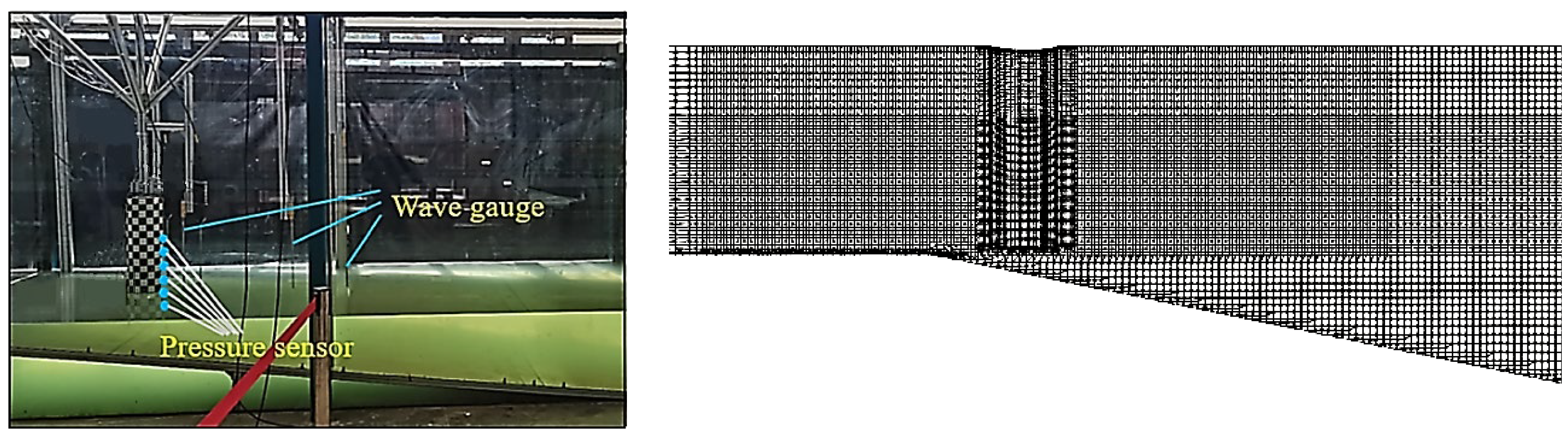
Jmse 12 00712 g001
Figure 2. Computational domain and numerical meshes for the sandglass-type floating body.
Jmse 12 00712 g002
Figure 3. Time-history curves of heave and pitch motions of the sandglass-type model obtained by two methods.
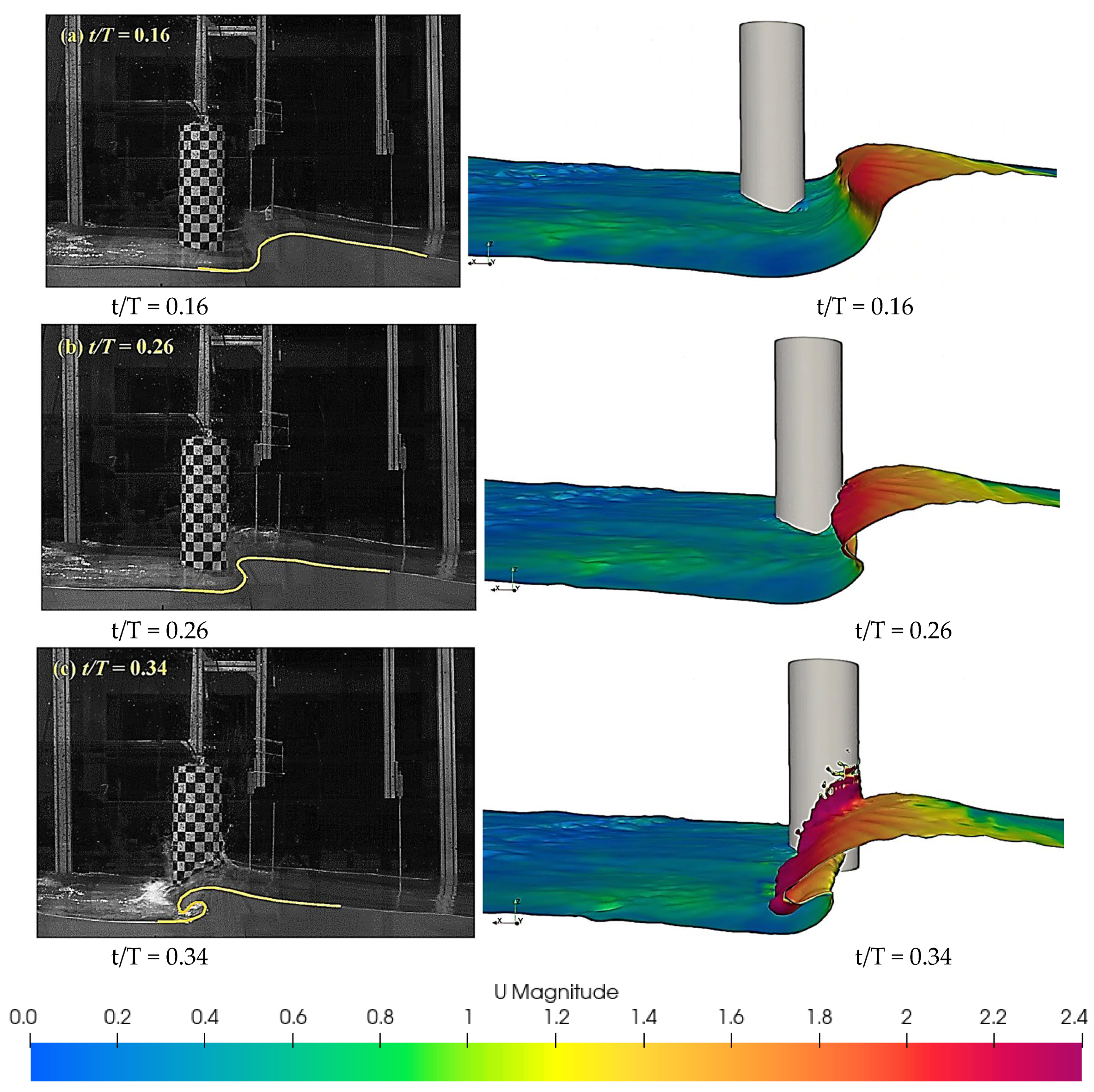
Jmse 12 00712 g003
Figure 4. Free surface and velocity contour of wave slamming on the front side of sandglass-type model.
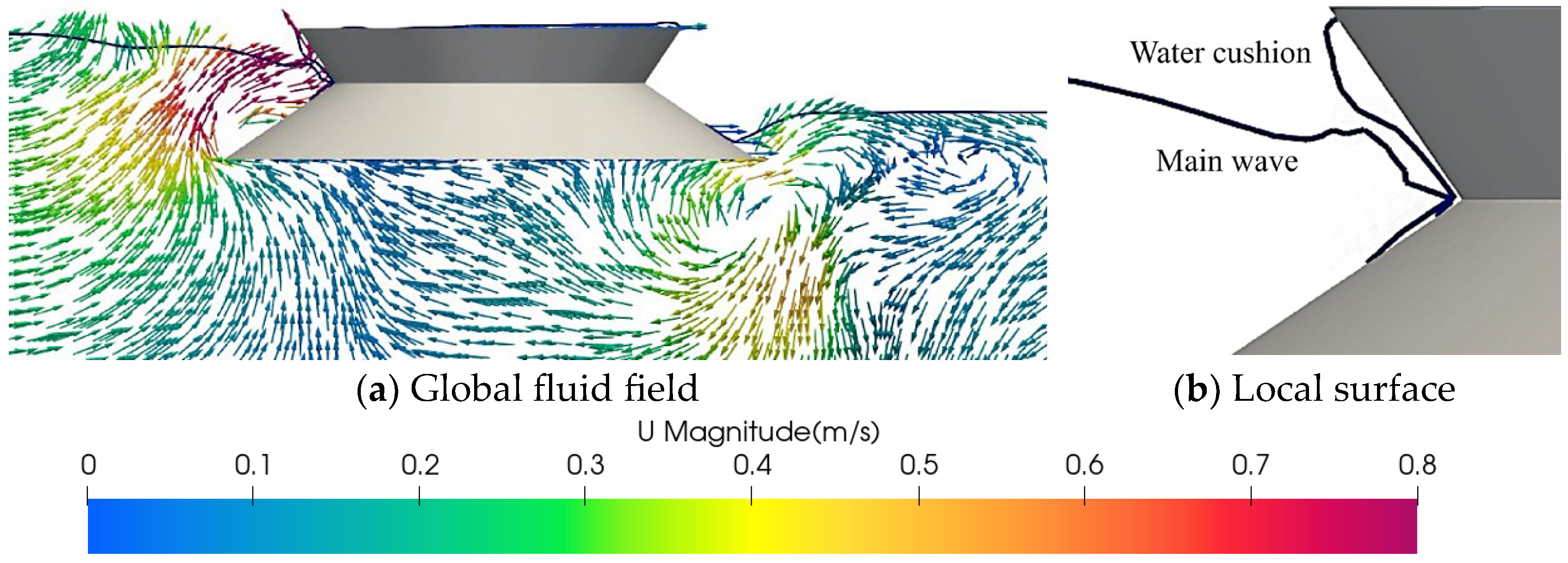
Jmse 12 00712 g004
Figure 5. Free surface and velocity contour of wave convergence at the rear end of sandglass-type model.
Jmse 12 00712 g005
Figure 6. Experimental setup and numerical meshes.
Jmse 12 00712 g006
Figure 7. Free surface velocity contour by experimental and numerical methods during wave slamming.
Jmse 12 00712 g007
Figure 8. Slamming pressures by numerical and experimental methods.
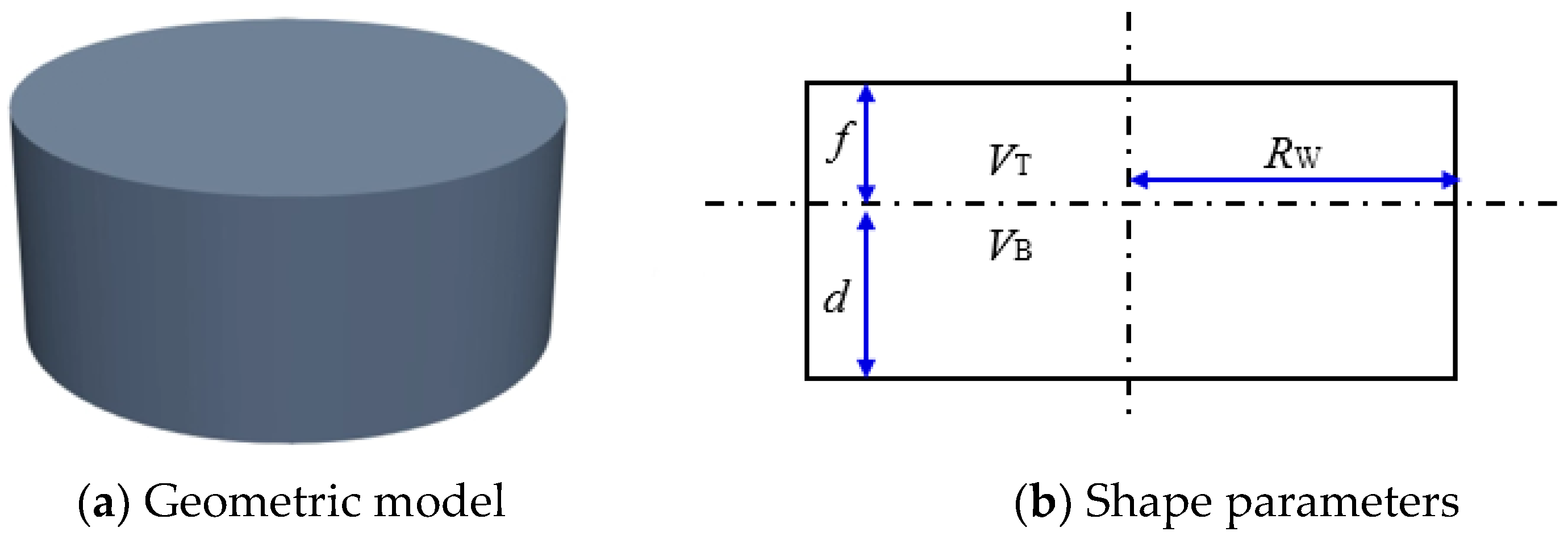
Jmse 12 00712 g008
Figure 9. Geometric model and shape parameters of the sandglass-type floating body.
Jmse 12 00712 g009
Figure 10. Computational domain and numerical meshes of the sandglass-type model.
Jmse 12 00712 g010
Figure 11. Geometric model and shape parameters of the cylindrical model.
Jmse 12 00712 g011
Figure 12. Computational domain and numerical meshes of the cylindrical model.
Jmse 12 00712 g012
Figure 13. Time histories of slamming pressure versus different meshes.
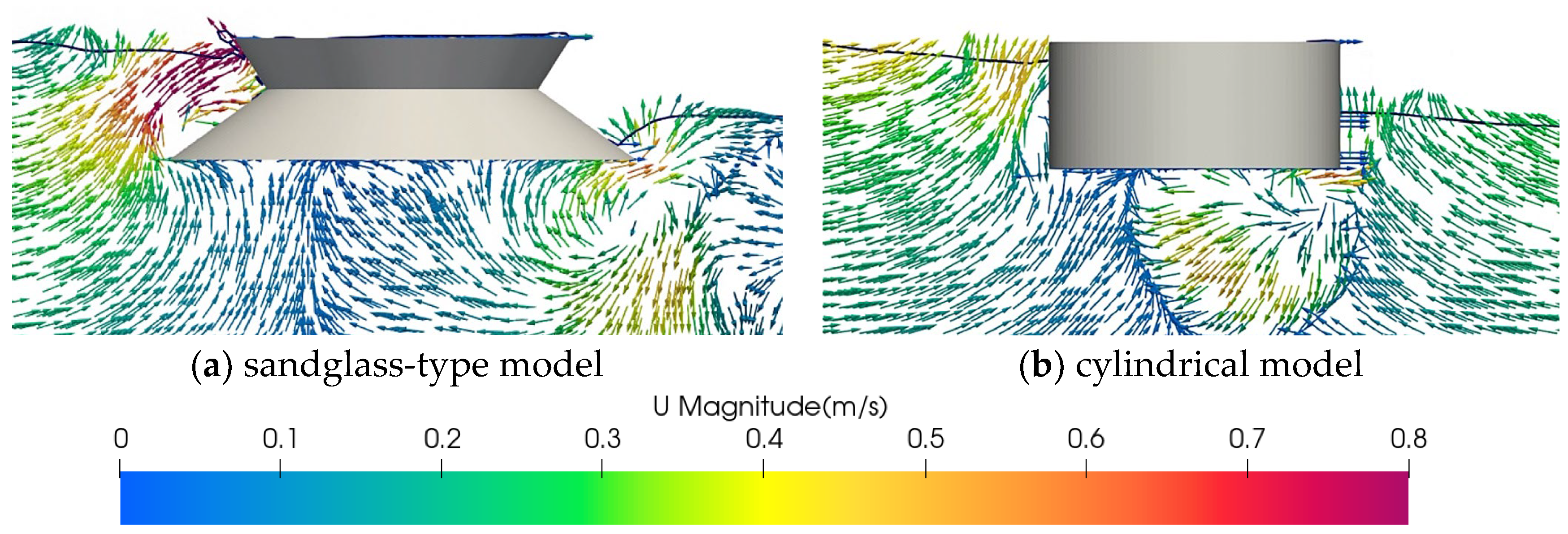
Jmse 12 00712 g013
Figure 14. Free surface velocity contour at classic moments for the sandglass-type model.
Jmse 12 00712 g014
Figure 15. Free surface velocity contour at classic moments for the cylindrical model.
Jmse 12 00712 g015
Figure 16. Velocity vector along the central longitudinal plane at classic moments for the sandglass-type model.
Jmse 12 00712 g016
Figure 17. Velocity vector along the central longitudinal plane at classic moments for the cylindrical model.
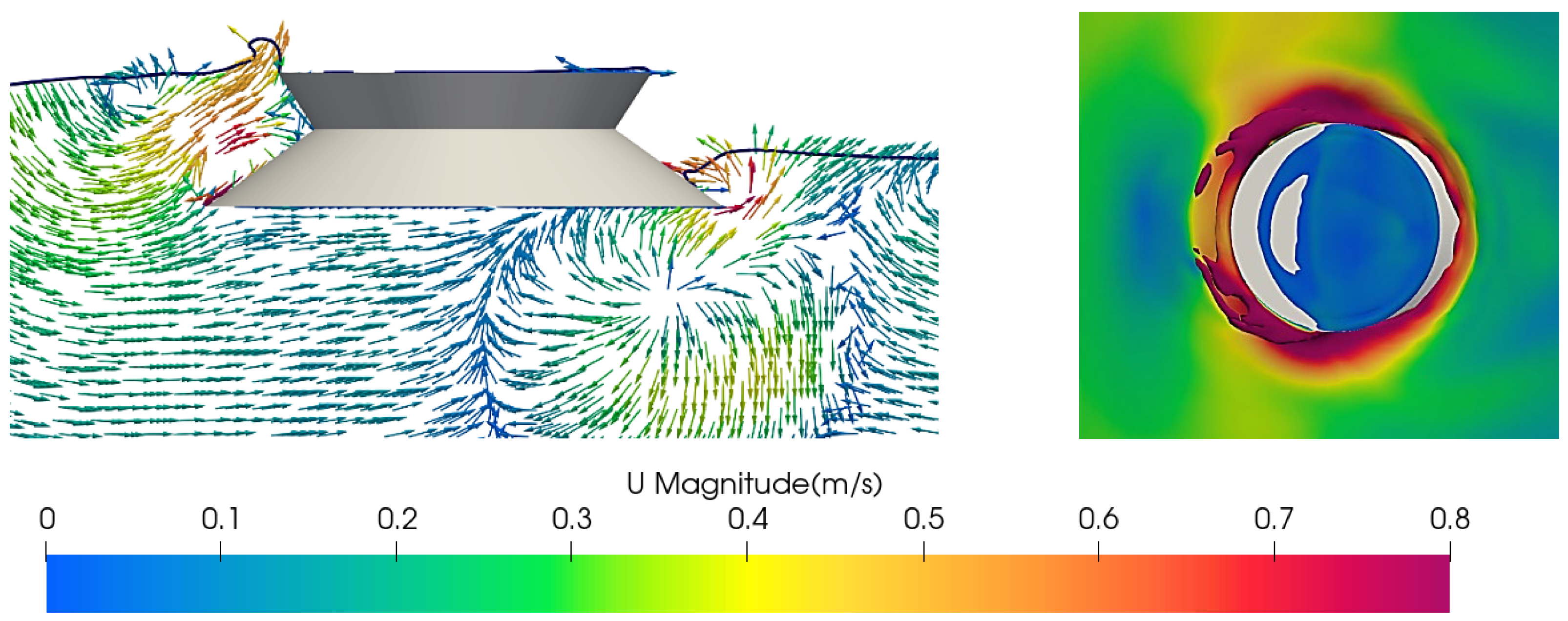
Jmse 12 00712 g017
Figure 18. Velocity vector along the central longitudinal plane and local wave surface including water cushion.
Jmse 12 00712 g018
Figure 19. Velocity vector along the central longitudinal plane during the slamming of main wave for two models.
Jmse 12 00712 g019
Figure 20. Wave contour and velocity vector during wave reflection and diffraction for the sandglass-type model.
Jmse 12 00712 g020
Figure 21. Wave contour and velocity vector during wave reflection and diffraction for the cylindrical model.
Jmse 12 00712 g021
Figure 22. Phenomenon of rooster tail caused by the wave convergence for the sandglass-type model.
Jmse 12 00712 g022
Figure 23. Phenomenon of side wave due to the gravity for the sandglass-type model.
Jmse 12 00712 g023
Figure 24. Phenomenon of rooster tail caused by the wave convergence for the cylindrical model.
Jmse 12 00712 g024
Figure 25. Phenomenon of side wave due to the gravity for the cylindrical model.
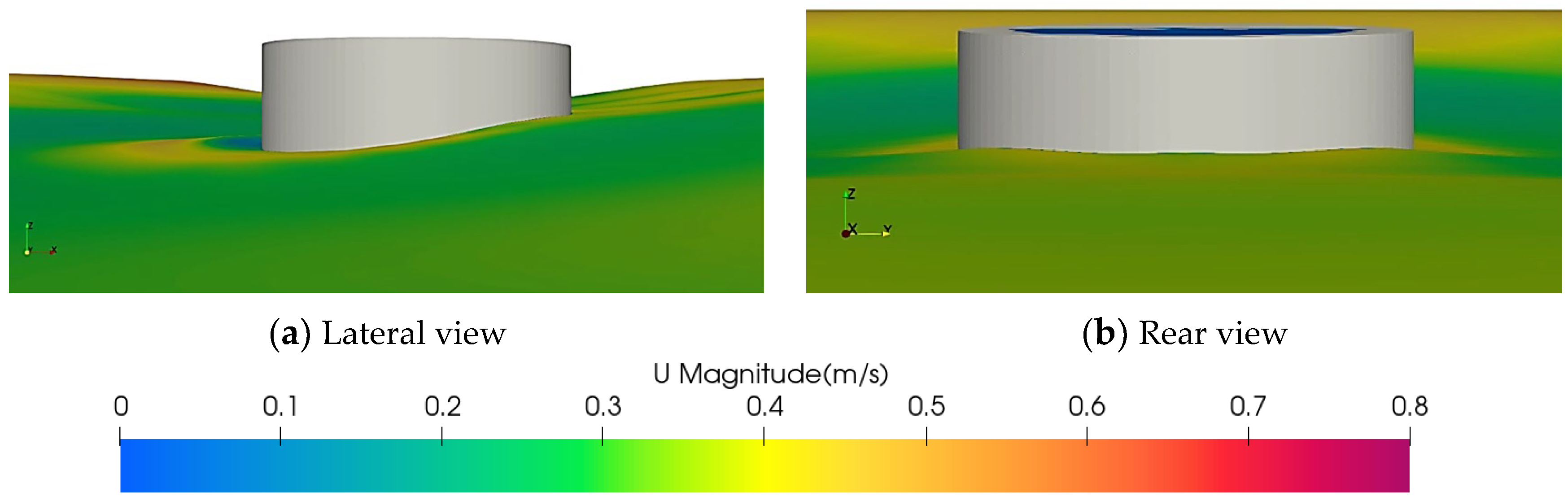
Jmse 12 00712 g025
Figure 26. Reflux along bottom and wave lifting for the sandglass-type model.
Jmse 12 00712 g026
Figure 27. Reflux along lower side and water tongue for the sandglass-type model.
Jmse 12 00712 g027
Figure 28. Reflux along bottom and wave lifting for the cylindrical model.
Jmse 12 00712 g028
Figure 29. Evolution of pressure distribution during wave slamming for the sandglass-type model, at the front view.
Jmse 12 00712 g029
Figure 30. Evolution of pressure distribution during wave slamming for the cylindrical model, at the front view.
Jmse 12 00712 g030
Figure 31. Arrangement of the monitoring points and the related coordinates for the sandglass-type model.
Jmse 12 00712 g031
Figure 32. Arrangement of the monitoring points and the related coordinates for the cylindrical model.
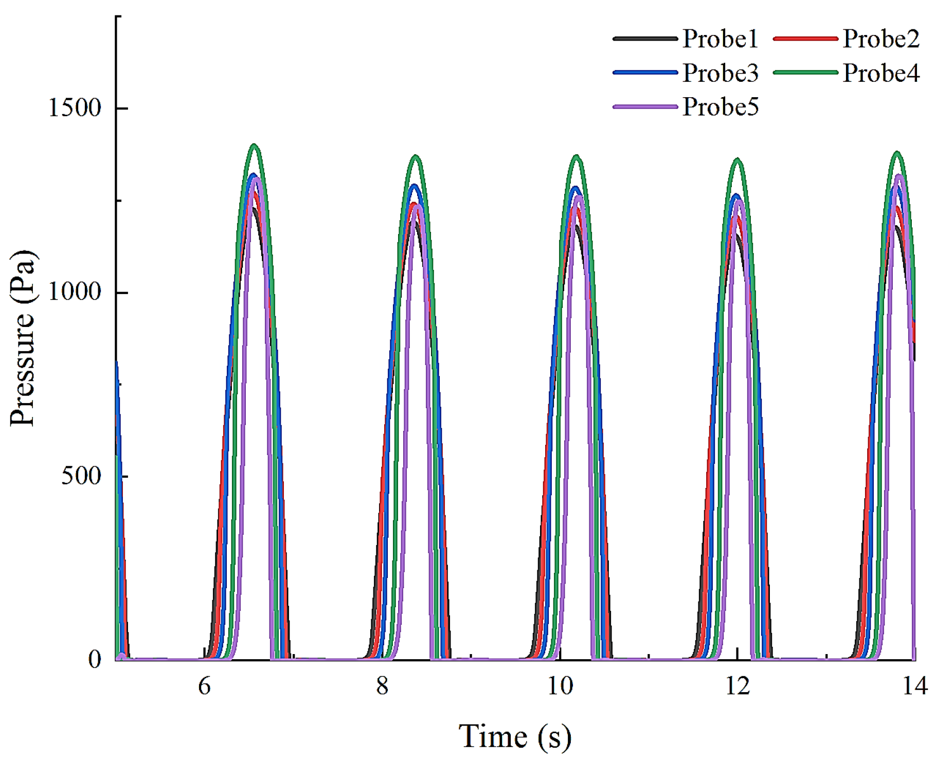
Jmse 12 00712 g032
Figure 33. Time histories of slamming pressure on various monitoring points for the sandglass-type model.
Jmse 12 00712 g033
Figure 34. Velocity vector and wave shape along the central longitudinal plane at different moments.
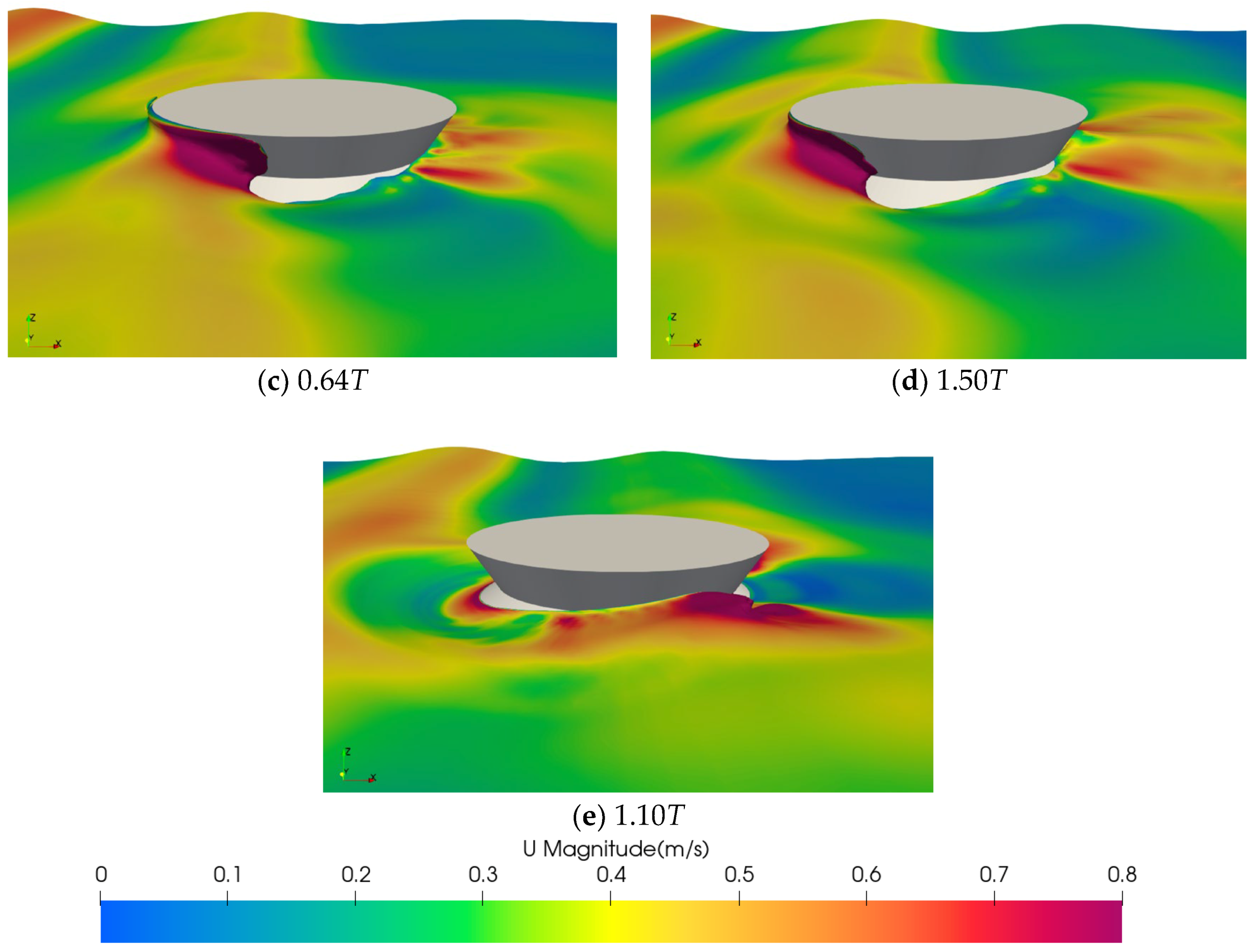
Jmse 12 00712 g034
Figure 35. Flow characteristic at the moment corresponding to the negative pressure at probe 6.
Jmse 12 00712 g035
Figure 36. Time histories of slamming pressure on various monitoring points for the cylindrical model.
Jmse 12 00712 g036
Figure 37. Time-variant characteristic of classic slamming pressure for the sandglass-type model.
Jmse 12 00712 g037
Figure 38. Time histories of slamming pressure at probe 1 under the short-wave condition.
Jmse 12 00712 g038
Figure 39. Wave surface at classic moments under the short-wave condition.
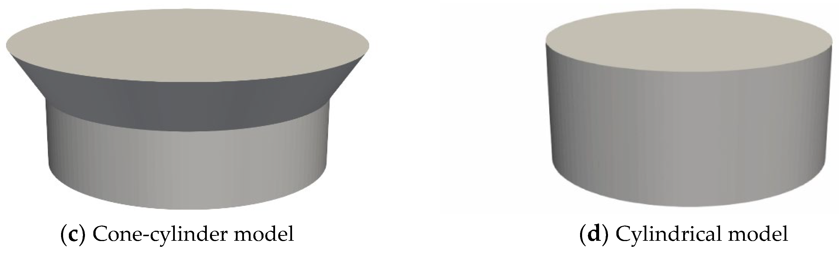
Jmse 12 00712 g039aJmse 12 00712 g039b
Figure 40. Geometrical model of four classic floating models.
Jmse 12 00712 g040aJmse 12 00712 g040b
Figure 41. Time histories of slamming pressure at probe 1 under different shapes.
Jmse 12 00712 g041
Figure 42. Free surface and velocity contour at classic moments for the cone-cylinder model.
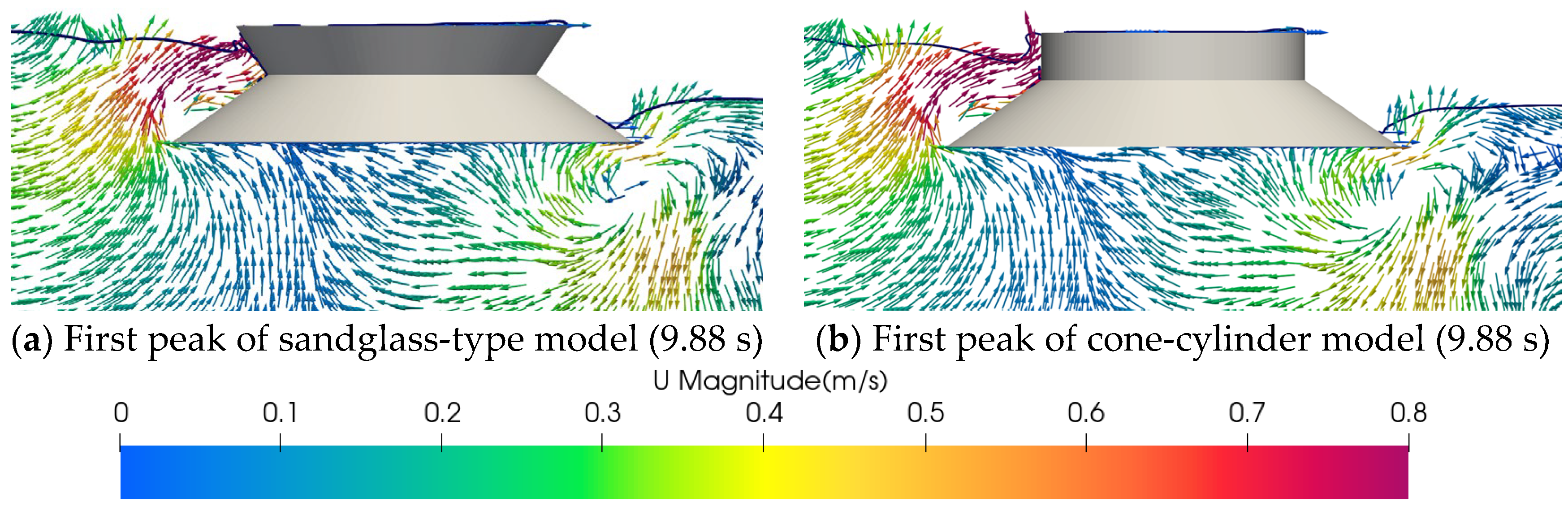
Jmse 12 00712 g042
Figure 43. Velocity vector along the central longitudinal plane at first peak of the sandglass-type and cone-cylinder floating bodies.
Jmse 12 00712 g043
Figure 44. Free surface velocity contour at second peak of the sandglass-type model and cone-cylinder model.
Jmse 12 00712 g044
Table 1. Main dimensions of the experimental sandglass-type model.
UnitValue
Radius of upper deckmm563.31
Freeboardmm285.71
Radius of waterline planemm374.29
Draughtmm188.11
Radius of lower bottommm642.94
Height between COG and bottommm120.00
Table 2. Mesh information in convergence study of Case 1.
MeshNΔx (m)Δy (m)Δz (m)
Coarse509,5180.0220.0220.021
Medium1,139,4000.0170.0170.016
Fine2,284,2000.0130.0130.013
Table 3. Average peak response of the model with different meshes.
MeshHeave (m)Relative DifferencePitch (Deg)Relative Difference
Coarse2.885.57%880.12%
Medium3.111.97%0.973%
Fine3.05-1.00-
Table 4. Comparison of heave motion responses between two methods (Unit: mm).
Numerical MethodModel Test
First crest2.34First trough−3.28First crest3.20First trough−3.29
Second crest2.96Second trough−3.37Second crest2.71Second trough−3.01
Third crest2.90Third trough−3.29Third crest3.35Third trough−3.61
Fourth crest3.18Fourth trough−3.51Fourth crest3.38Fourth trough−3.68
Fifth crest3.14Fifth trough−3.25Fifth crest3.34Fifth trough−3.46
Sixth crest3.31Sixth trough−3.12Sixth crest3.26Sixth trough−3.30
--Seventh trough−2.96--Seventh trough−3.23
Average crest2.97Average trough−3.25Average crest3.21Average trough−3.37
Average motion amplitude: 3.11Average motion amplitude: 3.29
Relative error: −5.31%
Table 5. Comparison of pitch motion responses between two methods (Unit: deg).
Numerical MethodModel Test
First crest0.65First trough−1.38First crest0.76First trough−0.94
Second crest1.11Second trough−1.33Second crest1.06Second trough−1.33
Third crest1.11Third trough−0.79Third crest0.80Third trough−0.64
Fourth crest0.85Fourth trough−0.85Fourth crest1.07Fourth trough−1.21
Fifth crest0.73Fifth trough−1.08Fifth crest0.73Fifth trough−0.84
Sixth crest0.91Sixth trough−1.02Sixth crest1.19Sixth trough−1.24
--Seventh trough−0.89--Seventh trough−1.07
Average crest0.89Average trough−1.05Average crest0.94Average trough−1.04
Average motion amplitude: 0.97Average motion amplitude: 0.99
Relative error: −1.58%
Table 6. Mesh information in convergence study of Case 2.
MeshNΔx (m)Δy (m)Δz (m)
Coarse1,585,1220.0130.0130.013
Medium3,095,9420.0100.0100.010
Fine6,028,7800.0080.0080.008
Table 7. Peak slamming pressure from different meshes.
MeshPeak Slamming Pressure (Pa)Relative Difference
Coarse406.712.99%
Medium451.53.40%
Fine467.4-
Table 8. Shape parameters of the sandglass-type model.
ItemsUnitValue
Radius of water-plane (RW)m0.374
Radius of top deck (RT)m0.465
Radius of bottom (RB)m0.643
Draft (d)m0.188
Freeboard (f)m0.137
Up angle (β)°56.432
Down angle (α)°35.000
Displacement volume (VB)m30.156
Table 9. Shape parameters of the cylindrical model.
ItemsUnitValue
Radius of water-plane (RW)m0.374
Radius of top deck (RT)m0.374
Radius of bottom (RB)m0.374
Draft (d)m0.188
Freeboard (f)m0.137
Displacement volume (VB)m30.083
Table 10. Wave parameters of the classic regular wave.
Typical Regular WaveUnitValue
Wave heightm15.0
Wave periods15.1
Wave height (1:70)m0.214
Wave period (1:70)s1.805
Table 11. Mesh information in convergence study of the sandglass-type model.
MeshNΔx (m)Δy (m)Δz (m)
Coarse1,096,3200.0220.0220.021
Medium1,918,5600.0170.0170.016
Fine3,315,6720.0130.0130.013
Table 12. Average slamming pressure on the model versus different meshes.
MeshAverage Slamming Pressure (Pa)Relative Difference
Coarse1737.211.98%
Medium1991.20.89%
Fine1973.6-
Disclaimer/Publisher’s Note: The statements, opinions and data contained in all publications are solely those of the individual author(s) and contributor(s) and not of MDPI and/or the editor(s). MDPI and/or the editor(s) disclaim responsibility for any injury to people or property resulting from any ideas, methods, instructions or products referred to in the content.

