Article

Experimental Results and Analysis of Midrange Underwater Asymmetric Wireless Power Transfer

1
Key Laboratory of Transport Industry of Marine Technology and Control Engineering, Shanghai Maritime University, Shanghai 201306, China
2
EverOne (Shanghai) Company Limited, Shanghai 200090, China
3
L@bISEN, ISEN Yncréa Ouest, 29200 Brest, France
*
Author to whom correspondence should be addressed.
J. Mar. Sci. Eng. 2024, 12(4), 567; https://doi.org/10.3390/jmse12040567
Submission received: 1 March 2024 / Revised: 22 March 2024 / Accepted: 25 March 2024 / Published: 27 March 2024
(This article belongs to the Special Issue Technological Oceanography Volume II)

Abstract

:
The eddy current loss caused by the conductivity of seawater results in a relatively low transfer efficiency of underwater wireless power transfer (WPT). And the transfer distance of the current WPT system is relatively short. Considering that most of the wireless power transfer devices in practical applications are asymmetric, few studies have explored the transfer characteristics of asymmetric midrange WPT in seawater. In this study, it is experimentally found that the load voltage and transfer efficiency of an asymmetric midrange WPT system with reduced primary balancing resistance in seawater are nearly twice as high as those of a symmetric one at a 50 cm transfer distance and a 410 kHz operation frequency with a 44.4 Ω load resistance. A new circuit model of the underwater WPT system with complex impedance and complex mutual inductance is then presented, and the load voltages predicted by the model are consistent highly with the experimental values; the model is then utilized for the explanation of the experimental observations. Changing the load resistance also improves the transfer efficiency of the system; however, the eddy current loss results in a relatively low transfer efficiency of 30.9% at an optimal load resistance of 90 Ω. The asymmetric midrange underwater WPT system can be applied in scenarios where the transfer distance is prioritized.

1. Introduction

Compared with the conventional charging method, wireless power transfer (WPT) technology is garnering increasing attention as a result of the discarding of the traditional wire bondage, making the charging power supply and charging equipment completely isolated, and better solving the problems of exposed wires, easily produced contact sparks, and poor mobility that exist in wired electrical power transfer [1,2,3,4,5,6,7]. It has been widely employed in electric vehicles [8,9], medical equipment, portable electronic devices, aerospace applications, and ocean-related applications. Underwater applications mainly involve the charging of underwater autonomous vehicles [10,11] and the powering of marine observation equipment [12].
Seawater is an electrically conductive medium that has a non-negligible effect on WPT systems. Most of the previous studies concluded that the transfer efficiency of WPT systems in seawater is lower when compared to that in air [13,14,15]. The main reason for this is that in a seawater environment, the time-varying electromagnetic field generates eddy currents throughout the medium, which affects the transfer efficiency of the WPT system. So, the influence of eddy currents is a major challenge for underwater WPT systems. Eddy currents can be equated to circuit parameters in some studies. Reference [16] proposed a T-shaped circuit model that equates the influences of eddy currents to three branch resistances. Reference [17] equated the eddy current to two resistances on the primary and secondary sides. References [16,17] analyzed the short-range transfer capability where an eddy current is regarded as a loss, finding that the transfer efficiency in seawater is lower when compared to that in air. In [18], it was concluded that in a uniform dissipative environment, the electromagnetic interaction between the driving current and the induced eddy current changes the self-impedance of the coil as well as the mutual inductance between them. Therefore, complex self-inductance and complex mutual inductance were proposed to depict the influences of eddy currents in a 46 MHz WPT system. The works of [16,17,18] all involve electromagnetic fields, which are more difficult to understand and calculate.
In order to minimize the effects of seawater on the WPT system, the system structure is changed to improve efficiency. Two transmitter coils were placed symmetrically near each side of the receiver coil in [19], and then the eddy current loss was found to be reduced to about half of that of a conventional system, and the transfer efficiency was improved by nearly 10%. Reference [20] added symmetrical shielding coils on primary and secondary coils to attenuate the electromagnetic field in the seawater, and then reduce the effects of eddy currents and improve the transfer efficiency. However, both of these circuit models add extra coils and increase the complexity of the circuit device. So, simpler circuit models are needed for analysis.
Most of the circuit models studied at present are symmetric and cannot deal with asymmetric situations in practical applications. WPT systems with asymmetric coils are analyzed in air in [21,22,23]. In [24], compared with traditional symmetric WPT systems, the coupling coefficient and load under asymmetric transmitting and receiving coils have different effects on the output power. There are fewer studies on asymmetric coil systems in seawater. In [25], couplers with symmetric and asymmetric structures were designed and compared for underwater unmanned systems. The influence of the circuit parameters on the output performance was explored in [24,25]. However, these two papers did not mention how to improve the transfer efficiency.
In [26], a medium to long transfer range is defined as one greater than or equal to that of a typical personal local-area network. In [27], the midrange is defined as a distance between devices that is at least a few times longer than the size of the device involved in the power transfer. Since neither [26] nor [27] define an upper limit for the transfer distance, in this paper, the midrange is defined as a distance between two coils that is at least greater than or equal to the outer diameter of the transmitter and receiver coils.
In [28], it was experimentally found that the transfer efficiency of a symmetric WPT system at midrange is much better in seawater when compared to that in air, and a three-coil circuit model was proposed to depict the experimental findings. There are more parameters in the asymmetric case, making the identification of the three-coil parameters in [28] more difficult. Therefore, the model is not applicable to the asymmetric case. Inspired by [16,17,18], circuits with complex impedance and complex mutual inductance are proposed in this study to characterize the asymmetric WPT system in seawater.
In this paper, the transfer characteristics of the WPT system at an operating frequency of about 460 kHz (unlike previous frequencies in tens of MHz [18]) are analyzed using a circuit model with complex impedance and complex mutual inductance. In symmetrical WPT systems, 50% power loss occurs at the primary side [28]; so, reducing the power loss at the primary side is an effective way to improve efficiency. In this paper, the power consumed at the primary side is reduced by decreasing the primary-side resistance and thus improving the transfer efficiency. The working principle is shown in Figure 1. Based on the asymmetric circuit model, it is experimentally found that reducing the primary balancing resistance can effectively improve the transfer efficiency at midrange.
This paper is composed of five sections. In Section 1, the previous study is described. Section 2 presents the experimental results, from which the relationship between efficiency and operating frequency as well as the primary-side resistance can be obtained. Section 3 establishes a new circuit model and analyzes its parameters. Section 4 provides a theoretical explanation of the experimental results by using the circuit model, and the experimental results are verified with theoretical calculations through the model. The new asymmetric circuit model can improve the efficiency to twice that of the symmetric case at a fixed 44.4 Ω load resistance. Section 5 presents a transfer characteristics analysis of midrange underwater WPT at variable load resistance. The optimal load resistance for optimizing the efficiency of the WPT system is found to be 90 Ω. The experimental values of the load voltage with variable load resistance are also verified through the model. Section 6 presents a summary of the whole paper.

2. Experimental Findings of Midrange WPT in Seawater at a Fixed Load Resistance

SS-compensated topologies are widely used due to their simple topology and load-independent properties. Compared to other topologies, SS compensation needs fewer components [29] and shows good performance in terms of efficiency over a wide range of load variations and has the advantage of easily realizing constant-current charging [30].
So, in order to explore the transfer characteristics at midrange, a dual-coil WPT system with a series–series topology at a resonant frequency of 460 kHz is constructed. The circuit topology of this WPT system in air is shown in Figure 2, where Us is the excitation voltage source; I1 is the current of the primary coil; L1 and C1 are the inductance and capacitance of the primary coil, respectively; I2 is the current of the secondary side; L2 and C2 are the inductance and capacitance of the secondary side, respectively; M0 is the mutual inductance between the primary and secondary coils in air; RL is the load resistance of the secondary side, which, considering that the actual battery internal resistance is 10–100 Ω [31,32] and taking into account the specific conditions of the laboratory, is set to 44.4 Ω; RB is the balancing resistor, wherein when RB = RL holds, the primary and secondary circuits are symmetrical, but otherwise, the circuits are asymmetrical; Rp1 is the internal resistance of the primary coil, the capacitance, and the power amplifier output resistor; and Rp2 is the internal resistance of the secondary-side capacitor and coil.
In this study, an asymmetric circuit structure is constructed by decreasing the primary-side resistance so that the impedances on both sides of the circuit are not equal. Then, the influence of circuit asymmetry on the transfer performance of underwater WPT is investigated by changing the primary balance resistance RB.
Analyzed theoretically, the smaller the primary balance resistance RB, the smaller the power consumed on RB and the larger the power received on the secondary side, and thus the higher the transfer efficiency of the system. For comparison, two resistances, 1/2RB and 1/9RB, are selected to compare with the symmetrical case.
The experimental platform of the underwater WPT system is shown in Figure 3. The primary and secondary coils are both planar 17-turn coils wound with AWG16 wire, with inner and outer diameters of 12 cm and 22.5 cm, respectively. The size of the glass tank is 120 cm × 70 cm × 70 cm, and the depth of the water is 65 cm. A 19.6 kg amount of salt is added to bring the salinity of the seawater to 3.5%, and the conductivity is measured with a conductivity meter (Shanghai Lichen Bangxi Instrument Technology Corporation Ltd: LC-DDB-1A, Shanghai, China) to be 3.34 S/m.
The magnetic permeability of seawater is approximately equal to 12.56 × 10⁻⁷ H/m [33]. The parameters of the system in air are shown in Table 1, which are measured with an LCR meter (GW Instek Corporation Ltd: LCR821, Suzhou, China) at a maximum frequency of 200 kHz. The internal resistances of the primary- and secondary-side circuits are 1.1 Ω and 0.5 Ω, respectively [34,35,36].
A sinusoidal signal generated by the signal generator (Tektronix Technology Ltd: AFG3102, Shanghai, China) is sent to a 10 W power amplifier (Rigol Technologies Corporation Ltd: PA1011, Beijing, China) for amplification. The power amplifier outputs a sinusoidal signal with a peak-to-peak value of 20 V to the primary coil of the WPT system. The peak-to-peak load voltage of the secondary coil is measured with an oscilloscope (Rigol: DS4014) for analysis. Four different coil distances are sampled from 23 cm to 50 cm in steps of 10 kHz to investigate the transfer characteristics of the system between 330 kHz and 700 kHz.

2.1. Experiment in Seawater

Experiments are carried out in seawater by placing two coils in the water tank and varying the primary balance resistance RB. The load voltages measured are shown in Figure 4.

2.2. Analysis of Experimental Results in Seawater

When the balancing resistance RB is not equal to the load resistance RL (i.e., 1/2RB and 1/9RB), there is a considerable load voltage between 400 and 500 kHz that is significantly higher than the symmetrical (RB = RL) case, as seen in Figure 4. In Figure 4a,b, the maximum load voltage at 1/9RB is higher than that at 1/2RB; this is consistent with the previous analysis that found that the lower the balancing resistance, the better the transfer ability of the system.
The transfer efficiency of the two-coil WPT system is [37]
η = U L I 2 × 100 % / ( U s I 1 cos θ )
where UL is the secondary load voltage, and θ is the phase difference between the primary voltage and current.
Figure 5 shows the load voltage on the secondary side for several cases at a distance of 50 cm. The resonance frequency is about 460 kHz in air, while the resonance frequency in seawater is shifted left to 410 kHz. Also, the load voltage is higher in seawater than in air for both symmetric and asymmetric cases at midrange.
At the 410 kHz resonant frequency, the load voltage and transfer efficiency of symmetric and asymmetric circuits are compared in Figure 6. The load voltage in seawater at 1/9RB is the largest and is maintained at about 8.24 V. The load voltage in the symmetric circuit is about 4.5 V, which is roughly half of that at 1/9RB (asymmetric case). As seen in Figure 6b, the smaller the RB, the higher the transfer efficiency in seawater at a distance between 23 cm and 50 cm. The transfer efficiency at 1/9RB (asymmetric case) is nearly twice that at RB (symmetrical case).

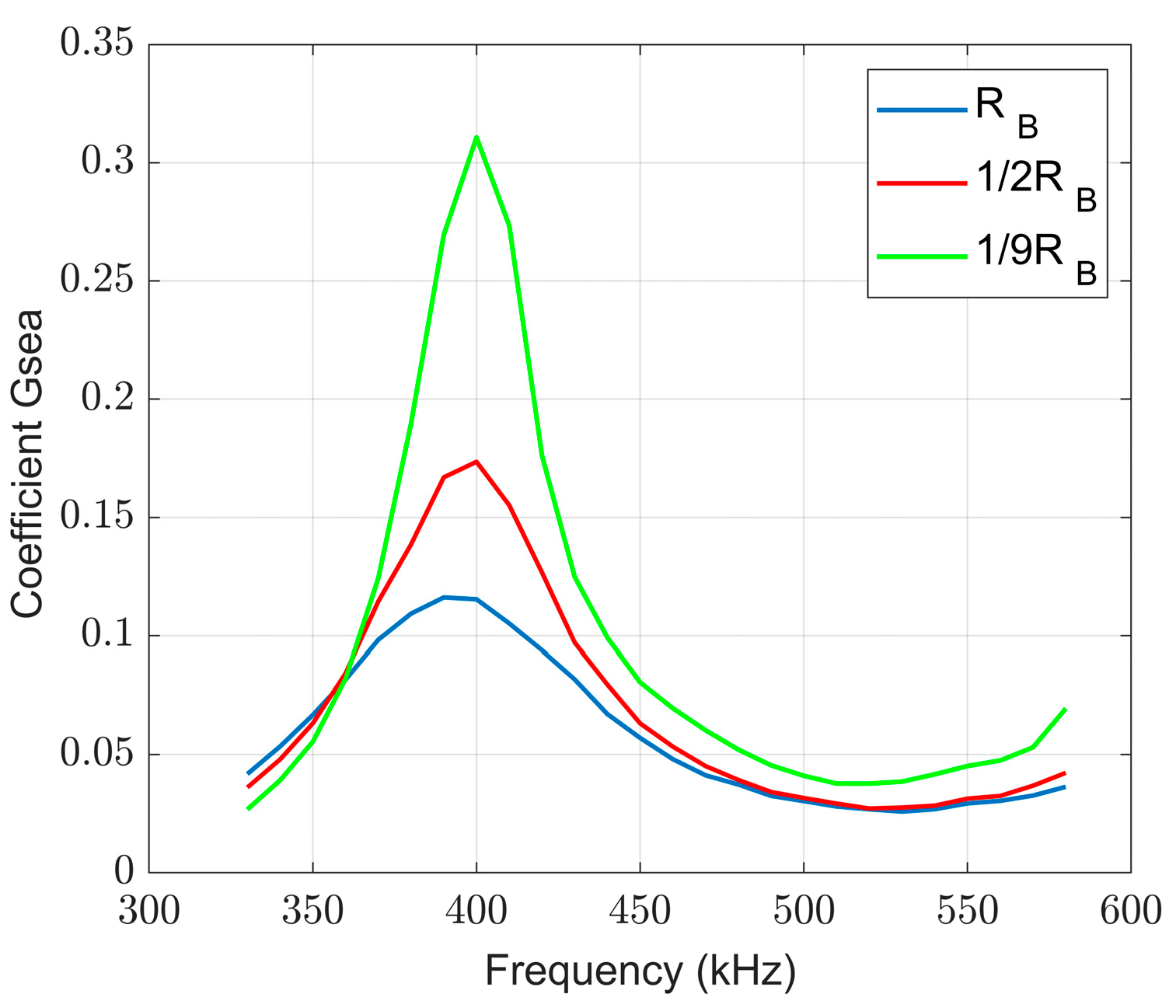
2.3. Impact of Variable Frequency and Variable Resistance RB on Efficiency

Figure 7 shows the transfer efficiency versus the frequency for a constant resistance RB. Figure 8 shows the resistance RB versus the transfer efficiency for several fixed frequencies. In Figure 7, the transfer efficiency is relatively large in the frequency range of 360–450 kHz when the resistance RB is constant. In Figure 8, increasing the resistance RB at a fixed frequency makes the transfer efficiency show a decreasing trend. Also, at around 400 kHz, the transfer efficiency at 45 Ω is almost half that at 5 Ω. Combining Figure 7 and Figure 8, it is observed that the transfer efficiency is relatively large when the frequency is concentrated at 360–450 kHz and the resistor RB is as small as possible.
Figure 9 shows the variation in the transfer efficiency when the resistance RB and the frequency are changed simultaneously. From Figure 9, it is found that there is a maximum transfer efficiency value at RB = 5 Ω and a frequency of 400 kHz. So, changing the operating frequency and varying the resistance simultaneously is more favorable for improving the transfer efficiency.
In seawater, eddy currents are the key factor influencing the transfer ability in WPT systems. In this study, circuits with complex impedance and complex mutual inductance are proposed to characterize the transfer of WPT systems underwater at midrange.

3. Underwater WPT System Circuit Model at a Fixed Load Resistance

In this section, the circuit of the underwater WPT system is first modeled. Then, the transfer characteristics at midrange are investigated.

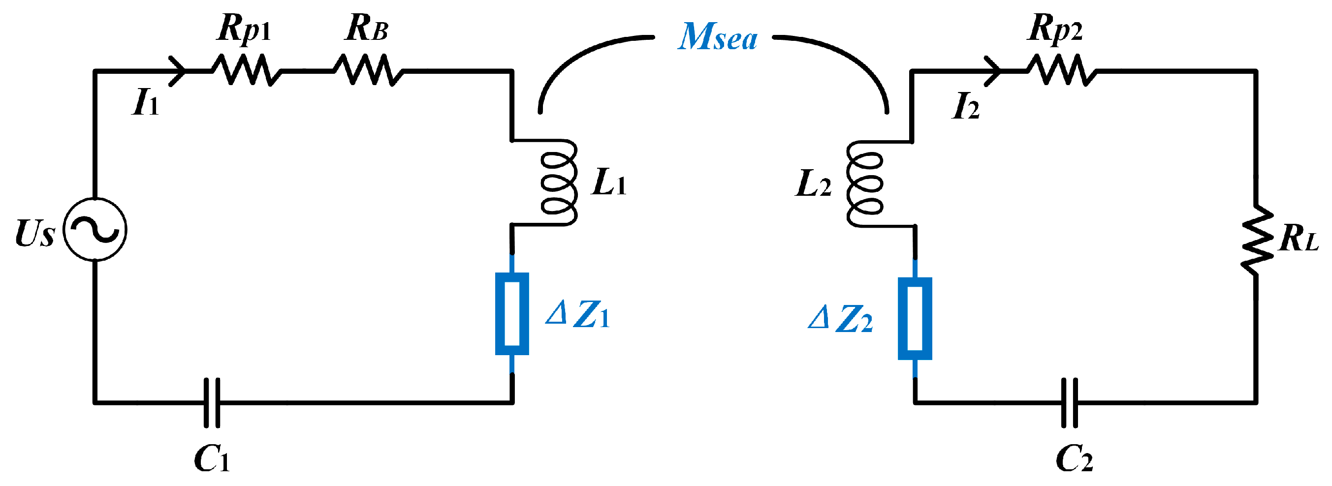
3.1. Circuit Modeling and Operating Principle

In this study, complex impedance (ΔZ) and complex mutual inductance (Msea) are proposed to describe the contributions of eddy currents in seawater. The circuit model of the underwater WPT system is shown in Figure 10.
From Figure 10, the impedances Z1 and Z2 of the primary and secondary sides are
Z 1 = R B + R p 1 + j ω L 1 j / ω C 1
Z 2 = R L + R p 2 + j ω L 2 j / ω C 2
According to the Kirchhoff’s voltage law, the equations for the two loops are
U s = ( Z 1 + Δ Z 1 ) I 1 j ω M s e a I 2
U 2 = ( Z 2 + Δ Z 2 ) I 2 j ω M s e a I 1
where ω is the angular frequency of the AC voltage source. The complex impedance ΔZ represents the coupling of the coil and the eddy current generated by the seawater. Msea is the complex mutual inductance between the primary and secondary coils in seawater and is the sum of the mutual inductance in air (M0) and the coupling of the coil and the eddy current in seawater (ME), i.e., Msea = M0 + ME. When in air, the additional complex impedance ΔZ and the additional mutual inductance ME are no longer present, i.e., ΔZ1 = ΔZ2 = ME = 0.
Complex impedance and complex mutual inductance can be found experimentally by opening the secondary circuit. This method reduces the complexity of the linear equations and is able to determine the complex impedance directly [38].
Then, the complex impedance is
Δ Z = [ U s / I 1 Z 1 ]
The complex mutual inductance is
M s e a = U 2 / j ω I 1
where I 1 = U R B / R B , I 2 = U L / R L , U R B is the measured voltage across resistor RB, UL is the measured voltage across load resistor RL, and U2 is the measured coil voltage when the secondary side is open.
In the case of the same resonance frequency, the alternating voltage provided by the power supply (Us) generates an alternating electromagnetic field around the primary-side coil. Then, the generated magnetic field will pass through the seawater medium and come to the secondary coil, an induced load voltage UL is produced in the secondary coil, and the power transfer is completed between these two coils.

3.2. Parametric Analysis of Symmetric Two-Coil Structures

Here, since both sides of the circuit are symmetrical, let ΔZ1 = ΔZ2 = ΔZ, and the equivalent complex impedance and complex mutual inductance can be found using (6) and (7), respectively. The eddy current equivalent parameters, i.e., complex impedance and complex mutual inductance, are shown in Figure 11 and Figure 12.
From Figure 11 and Figure 12, it is found that the complex impedance and complex mutual inductance are almost independent of the distance. The real part of the complex impedance and the imaginary part of the complex mutual inductance are always positive and indicate additional losses due to eddy currents, which is consistent with the resistance loss reported in [16,34]. The imaginary part of the complex impedance in Figure 11b can be positive or negative, indicating the complex behaviors of eddy currents; inductive at lower frequencies; and capacitive at higher frequencies. From Figure 12, the real part of the complex mutual inductance decreases with the frequency and the imaginary part increases with the frequency at higher frequencies.

3.3. Comparative Analysis of Asymmetric and Symmetric WPT Systems

Assuming that the complex impedances of the primary and secondary sides are equal, i.e., ΔZ1 = ΔZ2 = ΔZ, the above findings shows that the complex impedance and complex mutual inductance are almost independent of the distance. Here, only the case at a distance of 50 cm is analyzed, and the measured variations in the complex impedance and complex mutual inductance are shown in Figure 13 and Figure 14.
As shown in Figure 13, at higher frequencies, the larger the resistance RB, the faster the increase in the real part of the complex impedance. The imaginary part of the complex impedance decreases with the frequency and is almost independent of the resistance RB.
As seen in Figure 14, at higher frequencies, the real part of the complex mutual inductance becomes smaller with the frequency and is almost independent of the resistance RB. The imaginary part of the complex mutual inductance shows a complex Z-type relationship with the frequency. At a frequency of 410 kHz and a distance of 50 cm, the mutual inductance in air is M0 = 0.24 μH, and the complex mutual inductance in seawater is Msea ≈ (3.98 + j6.90) μH. The mutual inductance in air is much smaller than that in seawater.

4. Theoretical Explanation of Midrange Underwater WPT at a Fixed Load Resistance

4.1. Model-Predicted Secondary-Side Load Voltage

Once the complex impedance and complex mutual inductance are measured, the secondary-side load voltage can be predicted from (4) and (5) as follows:
| U L | = | I 2 R L | = | j ω M s e a U s R L / [ ( Z 1 + Δ Z 1 ) ( Z 2 + Δ Z 2 ) + ( ω M s e a ) 2 ] |
Figure 15 shows a three-dimensional comparison of the predicted theoretical load voltage from (8) with the experimental data. Figure 16 and Figure 17 show the two-dimensional load voltage versus the distance and frequency. These two figures show that the theoretical value of the model is consistent in general with the experimental measurements.

4.2. Reasons for the Transfer Being Better in Seawater Than in Air

The reflected impedance represents the capacity of a coil to obtain energy from a previous one. The reflected impedance of the secondary side to the primary coil in seawater is
Z 2 1 = ω 2 M s e a 2 / ( Z 2 + Δ Z )
The input power in seawater is
P in = U s 2 / | Z i n |
where Zin is the input impedance of the system, and Z i n = Z 1 + Δ Z + Z 2 1 .
The output power of the system in seawater is
P out = I 2 2 R L
The total transfer efficiency of the system is
η = I 2 2 R L | Z i n | / U s 2
From (2)–(4), the secondary-side current is
I 2 = j ω M s e a U s / [ ( Z 1 + Δ Z 1 ) + ( Z 2 + Δ Z 2 ) + ( ω M s e a ) 2 ]
Substituting (9) and (13) into (12), the transfer efficiency is found as
n = | ( ω M s e a ) 2 / [ ( Z 1 + Δ Z ) ( Z 2 + Δ Z ) + ( ω M s e a ) 2 ] | × ( R L / | Z 2 + Δ Z | )
Let Gsea = | ( ω M s e a ) 2 / [ ( Z 1 + Δ Z ) ( Z 2 + Δ Z ) + ( ω M s e a ) 2 ] | be a coefficient to analyze the transfer capacity in seawater.
According to (14), the transfer efficiency is related to mutual inductance and impedance. In seawater, the mutual inductance and impedance change because of the eddy currents. In air, the complex impedance ΔZ = 0 and the mutual inductance M0 are calculated using the simulation software Inca (version 2.1) [39]. So, Gair = | ( ω M 0 ) 2 / [ Z 1 Z 2 + ( ω M 0 ) 2 ] | is defined as a coefficient to analyze the transfer capacity in air.
Figure 18 shows the variation in G with the frequency for a symmetrical circuit in air at a transfer distance of 50 cm, with the peak of G being 460 kHz. Figure 19 shows the variation in G with the frequency for a symmetrical circuit in seawater at a transfer distance of 50 cm, with the peak of G being 410 kHz. The peak behaviors seen in Figure 18 and Figure 19 are consistent with the peaks in air versus seawater shown in Figure 5. The ratio of the coefficient G in seawater to that in air was calculated at a transfer distance of 50 cm. We found that G s e a / G a i r  > 166, which indicates that the transfer capability of the system in seawater is better when compared to that in air.
Moreover, 1/|Z2 + ΔZ| is a key part of calculating the transfer efficiency; so, Figure 20 demonstrates the inverse of the secondary-side impedance as a function of the frequency for seawater and air. The seawater peaks at 410 kHz, which is consistent with the peak behavior shown in Figure 5, Figure 15, Figure 17, and Figure 19. The peak in air is at 460 kHz, which matches the peak behavior seen in Figure 5 and Figure 18. The ratio of the secondary-side impedance in seawater to that in air is then calculated, and it is found that | ( Z 2 + Δ Z ) / Z 2 | < 2.07.
By comparing these two ratios, it is found that G dominates the transfer efficiency, which explains the phenomenon that the transfer efficiency in seawater is higher than in air, as shown in Figure 5.

4.3. Reasons for the Left Shift of Resonant Frequencies in Seawater

When the system is resonant, the circuit is resistive and the imaginary part of the total input impedance is 0. Figure 21 illustrates the imaginary part of the input impedance versus the frequency in seawater and air, wherein the imaginary part is 0 at about 420 kHz in seawater, and at about 460 kHz in air. This can explain the leftward shift of the resonant frequency of seawater in Figure 5. However, the frequency at which the imaginary part of the underwater input impedance is 0 is not necessarily the frequency (410 kHz) at which the load voltage on the secondary side is at its maximum [40]. From Figure 11b and Figure 13b, it can be seen that the imaginary part of the complex impedance is larger than 0 at 410 kHz, indicating that the imaginary part of the input impedance in seawater is increasing compared to that in air. At 410 kHz and a distance of 50 cm, the imaginary part of the input impedance in air is about −41.8 Ω, and the imaginary part of the input impedance in seawater is about −2.98 Ω, which is consistent with the phenomenon shown in Figure 20.

4.4. Reasons for the Transfer Being Better in Asymmetric Circuits Than in Symmetric Ones

As seen in Figure 5 and Figure 6, the secondary-side load voltage and the transfer efficiency of the asymmetric circuit with the smaller balancing resistor RB are higher than those of the symmetric one. This phenomenon is explained by the coefficient G that determines the transfer capability of this system. Figure 22 illustrates the coefficient G versus the frequency for different resistances RB at a transfer distance of 50 cm, wherein the coefficient G increases with decreasing resistance RB at around 410 kHz. When the system is operated at the 410 kHz seawater resonance frequency and the transfer distance is 50 cm, the ratios of the coefficients G are calculated as follows: G 1 / 2 R B / G R B = 1.4751, | ( Z 2 + Δ Z 1 / 2 R B ) / ( Z 2 + Δ Z R B ) | = 1.0698, G 1 / 9 R B / G 1 / 2 R B = 1.9606, | ( Z 2 + Δ Z 1 / 9 R B ) / ( Z 2 + Δ Z 1 / 2 R B ) | = 1.0577. With a decrease in the primary balance resistance RB, the increase in secondary-side impedance does not offset the system’s transfer capability, so the transfer efficiency increases as RB decreases.
Figure 23 illustrates the theoretical efficiency versus the frequency for different resistances RB at a transfer distance of 50 cm. In Figure 23, the peaks of the theoretical efficiencies at different resistances RB are all at approximately 410 kHz, which agrees with the peaks in Figure 5, Figure 15, Figure 17 and Figure 19. This indicates that the output of the model is in general agreement with the experimental measurements.
At a 410 kHz frequency and a 50 cm transfer distance, the theoretical transfer efficiencies are η R B ≈ 7.16%, η 1 / 2 R B ≈ 8.88%, and η 1 / 9 R B ≈ 12.07% in Figure 23, while in Figure 6, the experimental transfer efficiencies are 7.53%, 11.21%, and 15.25%, respectively. It can be seen that the experimental values and the predicted values are relatively close, and the main reason for the gaps between them is that the proposed model is not perfect, which needs to be improved further.
To summarize, reducing the balancing resistance in an underwater midrange WPT system does improve the transfer efficiency of the system. However, eddy currents consume a considerable amount of energy, which makes the transfer efficiency not very high.

5. Transfer Characteristics Analysis of Midrange Underwater WPT with a Variable Load Resistance

From the experiments and analyses presented in Section 2 and Section 4, it is concluded that the smaller the primary-side balance resistance, the higher the load voltage and transfer efficiency. By continuing to reduce the primary-side balance resistance to 1 Ω (the limitation of the experimental equipment), it is found experimentally that there is a higher efficiency of 15.9% (greater than the efficiency of 15.25% at 1/9RB) at 410 kHz for a transfer distance of 50 cm, which is consistent with the previous analysis. However, it is found experimentally that there is a maximum efficiency of 16.68% at 400 kHz under the 1 Ω primary balance resistance (greater than the efficiency of 15.9% at 410 kHz); so, the following analysis is based on the frequency of 400 kHz.
The load resistance is variable generally: e.g., the actual battery internal resistance changes usually from 10 Ω to 100 Ω [31,32]. The transfer characteristics under different load resistances are explored with a transfer distance of 50 cm, and a frequency of 400 kHz.

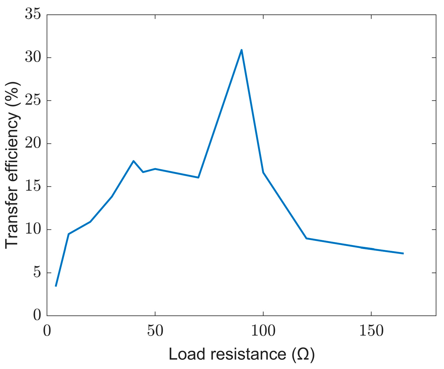
5.1. Experimental Findings with a Variable Load Resistance

Figure 24 shows the load voltage under different load resistances of the midrange WPT system in seawater with a transfer distance of 50 cm and a frequency of 400 kHz for a primary-side resistance of 1 Ω. It is found that there is a maximum value of load voltage for a load resistance of 90 Ω (approximated to 2RL). Figure 25 shows the transfer efficiency versus the load resistance of the midrange WPT system in seawater with a transfer distance of 50 cm and a frequency of 400 kHz for a primary-side resistance of 1 Ω. The transfer efficiency has a maximum value of 30.9% at a load resistance of 90 Ω (approximated to 2RL). So, it is concluded that the maximum transfer efficiency value is found when the load resistance is adjusted to 2RL.

5.2. Theoretical Calculations with a Variable Load Resistance

Theoretical calculations for an asymmetric circuit with a variable load resistance are carried out according to the same calculation method shown in Section 3. The primary-side resistance of the circuit is 1 Ω, with a frequency of 400 kHz and a distance of 50 cm. Assuming ΔZ1 = ΔZ2 = ΔZ, the complex impedance and complex mutual inductance can be calculated using Equations (6) and (7). The complex impedance is found to be constant in this calculation. The variation in the complex mutual inductance is shown in Figure 26.
In Figure 26a, the real part of the complex mutual inductance shows an overall increasing trend as the load resistance RL increases, except for a minimum value at RL = 30 Ω. In Figure 26b, the imaginary part of the complex mutual inductor shows a complex trend with the increase in RL. But, in general, the imaginary part shows a tendency to decrease and then increase, and its minimum value occurs at RL = 100 Ω.

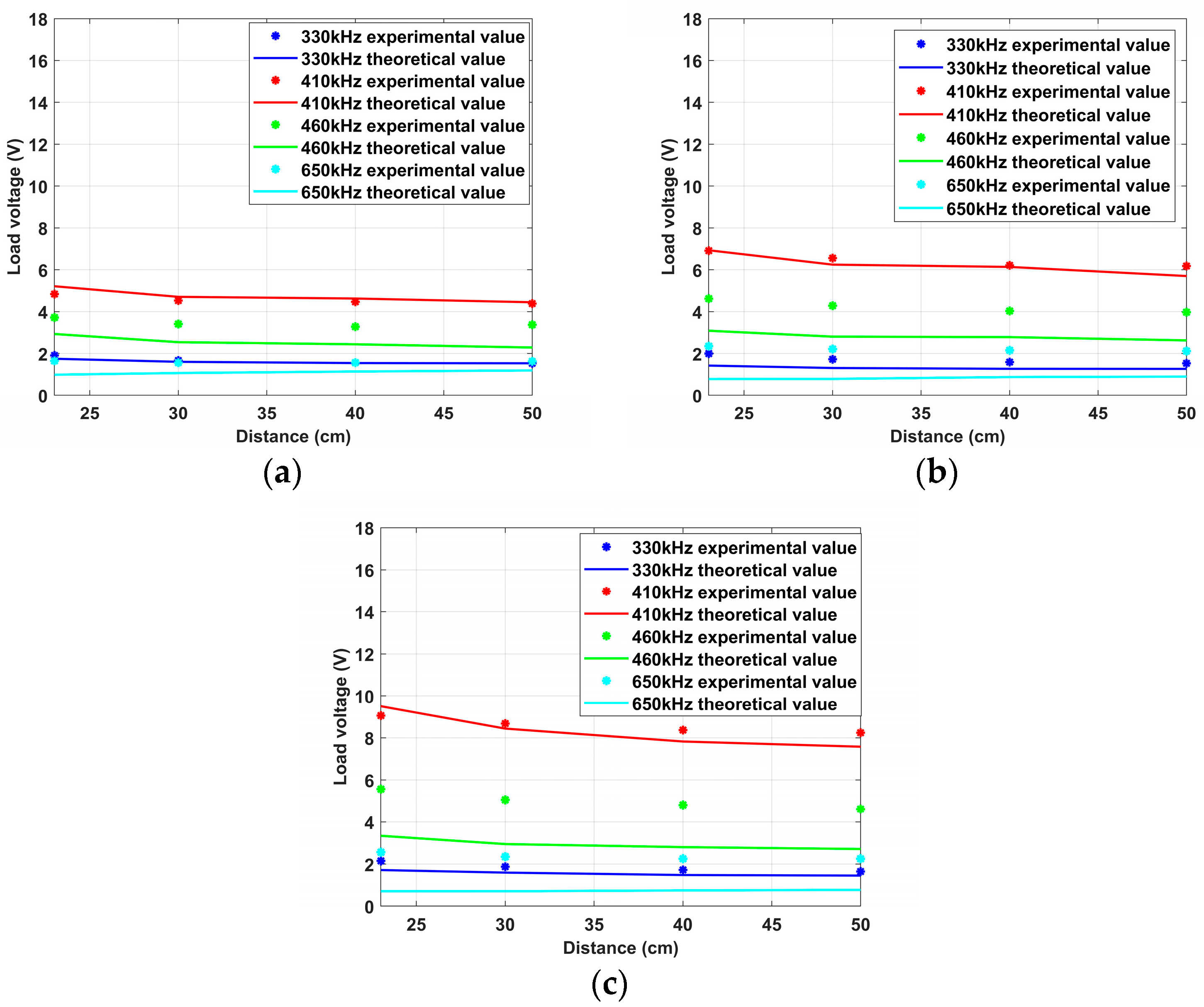
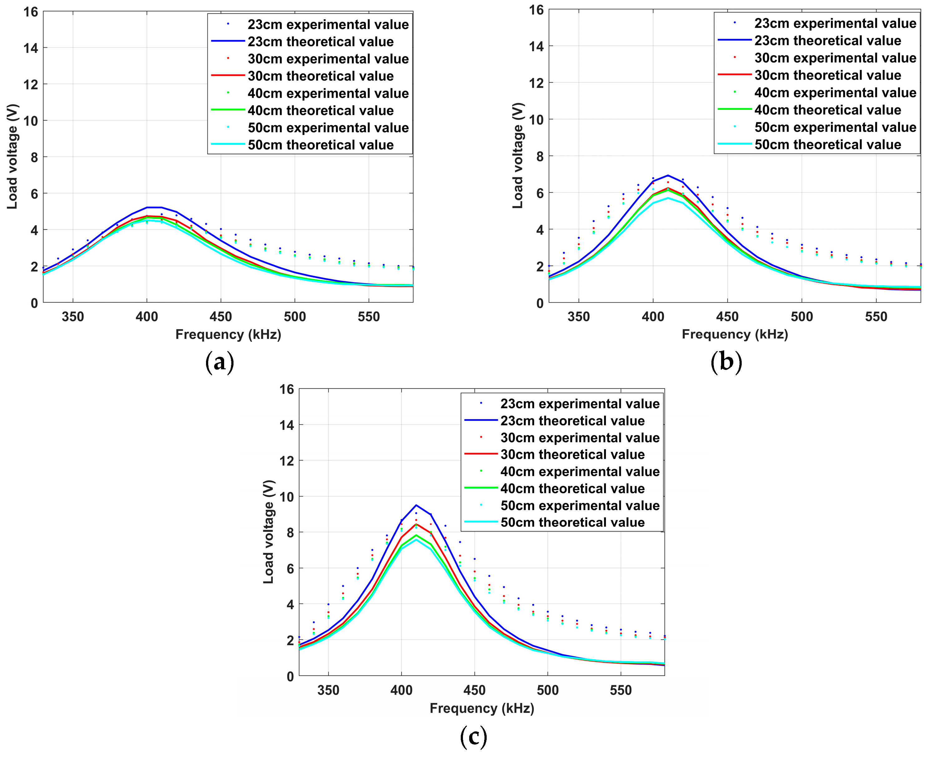
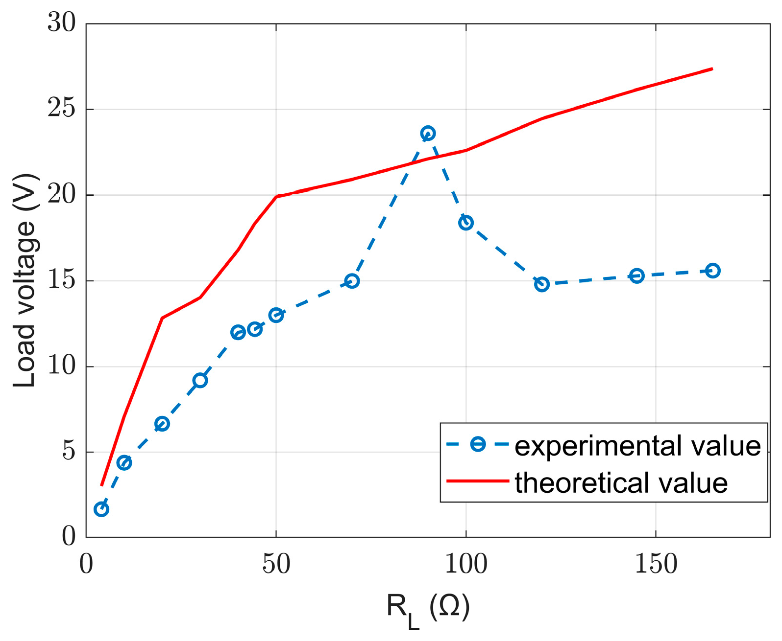
5.3. Comparison of Experimental and Theoretical Values of the Model

Substituting complex mutual inductance and complex impedance into the model, the load voltage can be predicted using (4) and (5). A comparison of the theoretical and experimental values of the model is shown in Figure 27. It is found that the theoretical values of the model are more consistent with the experimental values when the load resistance is lower than 100 Ω. When the load resistance is higher than 100 Ω, there is a certain gap between the theoretical values and the experimental values. Further efforts are needed to improve the model when the load resistance is variable.
To summarize, while keeping other conditions constant, changing the load resistance does influence the load voltage and the transfer efficiency of the midrange WPT system in seawater, and an optimal value of the load resistance that maximizes the efficiency is found at 90 Ω.

6. Conclusions

(1) In this paper, it is experimentally found that the two-coil WPT system with an asymmetrical circuit has a higher secondary-side load voltage than the symmetrical one at midrange in seawater. Thus, to explain this phenomenon, a circuit model with complex impedance and complex mutual inductance is proposed. The secondary-side load voltages predicted by this model are close to the experimental values at midrange. However, the efficiency predictions made by the model are not accurate enough and the model needs to be further improved. At short range, relatively bigger predicted errors also exist in the proposed model, and more research needs to be conducted on this.
(2) The coefficient G, which determines the transfer capability, is found to be much larger in seawater than in air, resulting in a higher secondary-side load voltage in seawater than in air. Also, when the system resonates, the frequency at which the imaginary part of the input impedance is 0 becomes smaller, resulting in a leftward shift of the resonant frequency in seawater to 410 kHz. In asymmetric circuits, the smaller the balancing resistance RB, the larger the coefficient G. Therefore, reducing RB increases the secondary-side load voltage and results in a higher transfer efficiency. The smaller RB is, the higher the transfer efficiency is, and it is speculated that the transfer efficiency should be even higher in seawater under the ideal condition when RB = 0 holds.
(3) Although the transfer efficiency (30.9%) of the midrange WPT system in seawater is relatively low when the balancing resistance is 1 Ω, the load resistance is 90 Ω, the operating frequency is 400 kHz, and the transfer distance is 50 cm, it can be applied to scenarios where the transfer distance is prioritized. In addition, the changes in complex impedance and complex mutual inductance in seawater may be explored with electromagnetic field theory in the near future.
(4) Eight coils with 3.4 m and 1.7 m diameters resonated at 650 Hz were placed with a 1.7 m gap for 10 m underwater transmission [41], and the efficiency measured was 20.7%. The 30.9% efficiency in this study is much better than that found in [41], despite the two-coil structure in this study being much simpler; the main reason for this is that a relatively higher frequency of 410 kHz is adopted in this work. In [42], it was found that the efficiency of a WPT system can reach up to 87%; however, its transfer distance is very short in the range of 3 cm–6 cm and the frequency is lower at 96 kHz, whereas the transfer distance in this study is in the midrange, reaching up to 50 cm, and the frequency is higher at 400 kHz.
(5) The range of load voltages is between 5 V and 10 V, which can be used to charge batteries for small underwater submarines [43].
(6) The coil size used in [34] is similar to that used in this paper, but it is more focused on short-range transfer, and it resonates at 373 kHz, while the work in [44] was also carried out at midrange (like this paper), but with a smaller-sized coil that resonates at 570 kHz. It is concluded that the frequency that distinguishes between different transfer conditions in seawater and air is related to the size of the coil and the transfer distance. Therefore, the resonant frequency of 410 kHz in seawater is not universal and cannot be applicable to all coils.
(7) In addition, considering that eddy currents may not be the same for different topologies under different operating conditions, the underwater transfer characteristics of other topologies such as LCC [29,30] need to be investigated further.
(8) AC load voltage is used in this study, and for actual applications, such as charging batteries, rectifiers should be used at the secondary side to provide DC output, and the DC load may be mapped to the AC load as shown in [45].
(9) Since salinity affects the conductivity of seawater and subsequently the transfer efficiency, a theoretical analysis of the transfer characteristics of asymmetric circuit WPT systems under different salinities will be carried out in the near future.
(10) In marine environments, interference from irregular marine currents and waves will change the position of unmanned marine vehicles, and thus the transfer distance and misalignment between transmitters and receivers will vary; adaptive mechanisms may be designed to deal with these issues [46,47].
(11) The limitation of this paper is the limited transfer distance studied: the furthest transfer distance analyzed in this study is 50 cm, and methods for longer transfer distances will be explored in the near future.

Author Contributions

Methodology, validation, formal analysis, and writing—original draft preparation, Y.C.; writing—review and editing, W.N.; review, Y.Y. and Y.A.; supervision, W.N. All authors have read and agreed to the published version of the manuscript.

Funding

This research received no external funding.

Institutional Review Board Statement

Not applicable.

Informed Consent Statement

Not applicable.

Data Availability Statement

The original contributions presented in the study are included in the article, further inquiries can be directed to the corresponding author/s.

Acknowledgments

The authors are very much grateful to Shanghai Maritime University, China, for providing all facilities for this research work.

Conflicts of Interest

Author Y.Y. was employed by the EverOne (Shanghai) Company Limited x. The remaining authors declare that the research was conducted in the absence of any commercial or financial relationships that could be construed as a potential conflict of interest.

References

  1. Elwakil, A.; Maundy, B.; Allagui, A. A Note on the Analysis of Two-Coil Wireless Power Transfer Systems. Circuits Syst. Signal Process. 2023, 42, 1808–1817. [Google Scholar] [CrossRef]
  2. Liu, Y.; Zhang, K.H.; Hu, A.P. Investigation of reactive power distribution between two coils of inductive power transfer system by Poynting vector analysis. Int. J. Electr. Power Energy Syst. 2022, 136, 107621. [Google Scholar] [CrossRef]
  3. Sumi, F.H.; Dutta, L.; Sarker, F. Future with wireless power transfer technology. J. Electr. Electron. Syst. 2018, 7, 1–7. [Google Scholar] [CrossRef]
  4. Wang, X.; Pang, J.Q.; Zhao, N.; Liu, L.F.; Dong, H.L.; Tan, Q.L.; Xiong, J.J. Lateral and angular misalignments of coil in wireless power transfer system. Sens. Actuator A Phys. 2022, 341, 113577. [Google Scholar] [CrossRef]
  5. Zhang, Z.; Pang, H.L.; Georgiadis, A.; Cecati, C. Wireless Power Transfer—An Overview. IEEE Trans. Ind. Electron. 2019, 66, 1044–1058. [Google Scholar] [CrossRef]
  6. Cai, T.; Lyu, F.; Wang, T.; Huang, F. Design of a Highly Compatible Underwater Wireless Power Transfer Station for Seafloor Observation Equipment. J. Mar. Sci. Eng. 2023, 11, 1205. [Google Scholar] [CrossRef]
  7. Luo, T.; Zhang, S. Design of Underwater Wireless Power Transmission System Based on Inductive Coupling. J. Mar. Sci. Eng. 2023, 11, 1699. [Google Scholar] [CrossRef]
  8. Bi, Z.C.; Keoleian, G.A.; Lin, Z.H.; Moore, M.R.; Chen, K.N.; Song, L.J.; Zhao, Z.M. Life cycle assessment and tempo-spatial optimization of deploying dynamic wireless charging technology for electric cars. Transp. Res. Part. C Emerg. Technol. 2019, 100, 53–67. [Google Scholar] [CrossRef]
  9. Sun, K.; Niu, W. SPWM Inverter Control for Wireless Constant Current and Voltage Charging. World Electr. Veh. J. 2023, 14, 111. [Google Scholar] [CrossRef]
  10. Wen, H.; Li, J.; Zhang, K.; Ye, J.; Yan, Z.; Song, B.; Tong, X. Enhancing Power Transmission Stability of AUV’s Wireless Power Transfer System with Compact Planar Magnetic Coupler. J. Mar. Sci. Eng. 2023, 11, 566. [Google Scholar] [CrossRef]
  11. Xia, T.; Zhang, X.; Zhu, Z.; Yu, H.; Li, H. An Adaptive Control Strategy for Underwater Wireless Charging System Output Power with an Arc-Shaped Magnetic Core Structure. J. Mar. Sci. Eng. 2023, 11, 294. [Google Scholar] [CrossRef]
  12. Teeneti, C.R.; Truscott, T.T.; Beal, D.N.; Pantic, Z. Review of wireless charging systems for autonomous underwater vehicles. IEEE J. Oceanic Eng. 2019, 46, 68–87. [Google Scholar] [CrossRef]
  13. Kuipers, J.; Bruning, H.; Bakker, S.; Rijnaarts, H. Near field resonant inductive coupling to power electronic devices dispersed in water. Sens. Actuator A Phys. 2012, 178, 217–222. [Google Scholar] [CrossRef]
  14. Zhang, K.H.; Zhu, Z.B.; Du, L.N.; Song, B.W. Eddy loss analysis and parameter optimization of the WPT system in seawater. J. Power Electron. 2018, 18, 778–788. [Google Scholar] [CrossRef]
  15. Bana, V.; Kerber, M.; Anderson, G.; Rockway, J.D.; Phipps, A. Underwater wireless power transfer for maritime applications. In Proceedings of the 2015 IEEE Wireless Power Transfer Conference (WPTC), Boulder, CO, USA, 13–15 May 2015. [Google Scholar] [CrossRef]
  16. Kim, J.; Kim, K.; Kim, H.; Kim, D.; Park, J.; Ahn, S. An efficient modeling for underwater wireless power transfer using Z-parameters. IEEE Trans. Electromagn. Compat. 2019, 61, 2006–2014. [Google Scholar] [CrossRef]
  17. Sun, P.; Wu, X.S.; Cai, J.; Wang, X.N.; Zhang, X.C.; Liang, Y.; Xiong, Q.; Rong, E.G. Eddy current loss analysis and frequency optimization design of double-sided LCC-IPT system in seawater environment. Sci. China Technol. Sci. 2022, 65, 407–418. [Google Scholar] [CrossRef]
  18. Chu, S.; Luloff, M.S.; Yan, J.; Petrov, P.; Stevens, C.J.; Shamonina, E. Magnetoinductive waves in attenuating media. Sci. Rep. 2021, 11, 7679. [Google Scholar] [CrossRef] [PubMed]
  19. Zhang, K.H.; Zhang, X.Y.; Zhu, Z.B.; Yan, Z.C.; Song, B.W.; Mi, C.C. A new coil structure to reduce eddy current loss of WPT systems for underwater vehicles. IEEE Trans. Veh. Tech. 2018, 68, 245–253. [Google Scholar] [CrossRef]
  20. Wang, Y.S.; Song, B.W.; Mao, Z.Y. Application of shielding coils in underwater wireless power transfer systems. J. Mar. Sci. Eng. 2019, 7, 267. [Google Scholar] [CrossRef]
  21. Kurs, A.; Moffatt, R.; Soljačić, M. Simultaneous mid-range power transfer to multiple devices. Appl. Phys. Lett. 2010, 96, 044102. [Google Scholar] [CrossRef]
  22. Li, Y.; Song, K.; Li, Z.J.; Jiang, J.H.; Zhu, C.B. Optimal efficiency tracking control scheme based on power stabilization for a wireless power transfer system with multiple receivers. Energies 2018, 11, 1232. [Google Scholar] [CrossRef]
  23. Huang, R.H.; Zhang, B.; Qiu, D.Y.; Zhang, Y.Q. Frequency splitting phenomena of magnetic resonant coupling wireless power transfer. IEEE Trans. Magn. 2014, 50, 1–4. [Google Scholar] [CrossRef]
  24. Guan, Z.P.; Zhang, B.; Qiu, D.Y. Influence of Asymmetric Coil Parameters on the Output Power Characteristics of Wireless Power Transfer Systems and Their Applications. Energies 2019, 12, 1212. [Google Scholar] [CrossRef]
  25. Li, J.C.; Feng, J.N.; Dou, X.; Yang, H.Y.; Zhang, X.; Ni, K. Design and Comparative Analysis of Symmetric and Asymmetric Couplers for Underwater Wireless Power Transmission System. In Proceedings of the 2022 International Conference on Wireless Power Transfer (ICWPT2022), Chongqing, China, 16–19 September 2022. [Google Scholar] [CrossRef]
  26. Low, Z.N.; Chinga, R.A.; Tseng, R.; Lin, J. Design and test of a high-power high-efficiency loosely coupled planar wireless power transfer system. IEEE Trans. Ind. Electron. 2008, 56, 1801–1812. [Google Scholar] [CrossRef]
  27. Kurs, A.; Karalis, A.; Moffatt, R.; Joannopoulos, J.D.; Fisher, P.; Soljacic, M. Wireless power transfer via strongly coupled magnetic resonances. Science 2007, 317, 83–86. [Google Scholar] [CrossRef]
  28. Niu, W.Q.; Yu, X.J.; Zhang, W.T. Experimental results and analysis of midrange underwater wireless power transfer. Int. J. Circuit Theory Appl. 2023, 51, 2674–2688. [Google Scholar] [CrossRef]
  29. Li, W.H.; Zhao, H.; Deng, J.J.; Li, S.Q.; Mi, C.C. Comparison study on SS and double-sided LCC compensation topologies for EV/PHEV wireless chargers. IEEE Trans. Veh. Tech. 2015, 65, 4429–4439. [Google Scholar] [CrossRef]
  30. Corti, F.; Paolucci, L.; Reatti, A.; Grasso, F.; Pugi, L.; Tesi, N.; Grasso, E.; Nienhaus, M. A comprehensive comparison of resonant topologies for magnetic wireless power transfer. In Proceedings of the 2020 IEEE 20th Mediterranean Electrotechnical Conference (MELECON), Palermo, Italy, 16–18 June 2020. [Google Scholar] [CrossRef]
  31. Qu, X.; Han, H.; Wong, S.-C.; Chi, K.T.; Chen, W. Hybrid IPT topologies with constant current or constant voltage output for battery charging applications. IEEE Trans. Power Electron. 2015, 30, 6329–6337. [Google Scholar] [CrossRef]
  32. Wen, H.; Wang, P.; Li, J.; Yang, J.; Zhang, K.; Yang, L.; Zhao, Y.; Tong, X. Improving the Misalignment Tolerance of Wireless Power Transfer System for AUV with Solenoid-Dual Combined Planar Magnetic Coupler. J. Mar. Sci. Eng. 2023, 11, 1571. [Google Scholar] [CrossRef]
  33. Holmes, J.J. Ocean Electromagnetics. In Springer Handbook of Ocean Engineering; Dhanak, M.R., Xiros, N.I., Eds.; Springer International Publishing: Cham, Switzerland, 2016; pp. 177–196. [Google Scholar] [CrossRef]
  34. Zhang, K.H.; Ma, Y.S.; Yan, Z.C.; Di, Z.F.; Song, B.W.; Hu, A.P. Eddy current loss and detuning effect of seawater on wireless power transfer. IEEE J. Emerg. Sel. Top. Power Electron. 2020, 8, 909–917. [Google Scholar] [CrossRef]
  35. Zhang, K.; Du, L.; Zhu, Z.; Song, B.; Xu, D. A normalization method of delimiting the electromagnetic hazard region of a wireless power transfer system. IEEE Trans. Electromagn. Compat. 2017, 60, 829–839. [Google Scholar] [CrossRef]
  36. Zhang, K.-H.; Zhu, Z.-B.; Song, B.-W.; Xu, D.-M. A power distribution model of magnetic resonance WPT system in seawater. In Proceedings of the 2016 IEEE 2nd annual southern power electronics conference (SPEC), Auckland, New Zealand, 5–8 December 2016. [Google Scholar] [CrossRef]
  37. Kiani, M.; Ghovanloo, M. A figure-of-merit for designing high-performance inductive power transmission links. IEEE Trans. Ind. Electron. 2012, 60, 5292–5305. [Google Scholar] [CrossRef]
  38. Dodd, C.; Deeds, W. Analytical solutions to eddy-current probe-coil problems. J. Appl. Phys. 1968, 39, 2829–2838. [Google Scholar] [CrossRef]
  39. Computer Programs. Available online: http://www.coe.ufrjbr/~acmq/programs/ (accessed on 12 December 2021).
  40. Niu, W.Q.; Chu, J.X.; Gu, W.; Shen, A.D. Exact Analysis of Frequency Splitting Phenomena of Contactless Power Transfer Systems. IEEE Trans. Circuits Syst. I Regul. Pap. 2013, 60, 1670–1677. [Google Scholar] [CrossRef]
  41. Hasaba, R.; Okamoto, K.; Kawata, S.; Eguchi, K.; Koyanagi, Y. Magnetic resonance wireless power transfer over 10 m with multiple coils immersed in seawater. IEEE Trans. Microw. Theory Tech. 2019, 67, 4505–4513. [Google Scholar] [CrossRef]
  42. Xu, F.; Huang, H. Frequency selection for underwater wireless power transfer based on the analysis of eddy current loss. AEU-Int. J. Electron. Commun. 2023, 163, 154618. [Google Scholar] [CrossRef]
  43. Bradley, A.M.; Feezor, M.D.; Singh, H.; Sorrell, F.Y. Power systems for autonomous underwater vehicles. IEEE J. Oceanic Eng. 2001, 26, 526–538. [Google Scholar] [CrossRef]
  44. Niu, W.Q.; Ye, C.; Gu, W. Circuit coupling model containing equivalent eddy current loss impedance for wireless power transfer in seawater. Int. J. Circuits Syst. Signal Process. 2021, 15, 410–416. [Google Scholar] [CrossRef]
  45. Song, K.; Li, Z.J.; Jiang, J.H.; Zhu, C.B. Constant current/voltage charging operation for series–series and series–parallel compensated wireless power transfer systems employing primary-side controller. IEEE Trans. Power Electron. 2017, 33, 8065–8080. [Google Scholar] [CrossRef]
  46. Ding, S.; Niu, W.; Gu, W. Lateral misalignment tolerant wireless power transfer with a tumbler mechanism. IEEE Access 2019, 7, 125091–125100. [Google Scholar] [CrossRef]
  47. Niu, W.; Jiang, J.; Ye, C.; Gu, W. Frequency splitting suppression in wireless power transfer using hemispherical spiral coils. AIP Adv. 2022, 12, 055016. [Google Scholar] [CrossRef]
Figure 1. Working principle of asymmetric circuit underwater wireless power transfer.
Jmse 12 00567 g001
Figure 2. The circuit structure of the WPT system in air.
Jmse 12 00567 g002
Figure 3. Experimental platform of the underwater WPT system (a,b).
Jmse 12 00567 g003
Figure 4. Load voltages in seawater. (a) RB (symmetric); (b) 1/2RB (asymmetric); (c) 1/9RB (asymmetric).
Jmse 12 00567 g004
Figure 5. Load voltages for different cases at a transfer distance of 50 cm.
Jmse 12 00567 g005
Figure 6. Comparison between symmetric and asymmetric circuits for the WPT system in seawater at the 410 kHz resonant frequency. (a) Load voltage; (b) transfer efficiency.
Jmse 12 00567 g006
Figure 7. The transfer efficiency versus the frequency for a constant resistance RB at a transfer distance of 50 cm.
Jmse 12 00567 g007
Figure 8. The transfer efficiency versus the resistance RB for fixed frequencies at a transfer distance of 50 cm.
Jmse 12 00567 g008
Figure 9. The variation in transfer efficiency when the resistance RB and the frequency are changed simultaneously.
Jmse 12 00567 g009
Figure 10. Circuit model of the underwater WPT system.
Jmse 12 00567 g010
Figure 11. The measured complex impedance versus the frequency at four distances. (a) Real part; (b) imaginary part.
Jmse 12 00567 g011
Figure 12. The measured complex mutual inductance versus the frequency at four distances. (a) Real part; (b) imaginary part.
Jmse 12 00567 g012
Figure 13. The measured complex impedance versus the frequency at 50 cm. (a) Real part; (b) imaginary part.
Jmse 12 00567 g013
Figure 14. The measured complex mutual inductance versus the frequency at 50 cm. (a) Real part; (b) imaginary part.
Jmse 12 00567 g014
Figure 15. Three-dimensional diagrams of the secondary-side load voltage in seawater. (a) RB (symmetric); (b) 1/2RB; (c) 1/9RB. The red solid lines represent the measured data and the blue solid lines represent the theoretical values.
Jmse 12 00567 g015
Figure 16. Experimental and theoretical values of load voltage versus the distance in seawater. (a) RB (symmetric); (b) 1/2RB; (c) 1/9RB.
Jmse 12 00567 g016
Figure 17. Experimental and theoretical values of load voltage versus the frequency in seawater. (a) RB (symmetric); (b) 1/2RB; (c) 1/9RB.
Jmse 12 00567 g017
Figure 18. Coefficient Gair versus frequency at a transfer distance of 50 cm in air (symmetric, RB = RL).
Jmse 12 00567 g018
Figure 19. Coefficient Gsea versus frequency at a transfer distance of 50 cm in seawater (symmetric, RB = RL).
Jmse 12 00567 g019
Figure 20. The inverse of the secondary-side impedance versus the frequency at a transfer distance of 50 cm (symmetric, RB = RL).
Jmse 12 00567 g020
Figure 21. Imaginary part of the input impedance versus the frequency in seawater and air.
Jmse 12 00567 g021
Figure 22. Coefficient Gsea versus frequency for different resistances RB at a transfer distance of 50 cm.
Jmse 12 00567 g022
Figure 23. Theoretical efficiency versus frequency for different resistances RB at a transfer distance of 50 cm.
Jmse 12 00567 g023
Figure 24. Load voltage under different load resistances in seawater with a primary-side resistance of 1 Ω, a transfer distance of 50 cm, and a frequency of 400 kHz.
Jmse 12 00567 g024
Figure 25. Transfer efficiency under different load resistances in seawater for a primary-side resistance of 1 Ω, a transfer distance of 50 cm, and a frequency of 400 kHz.
Jmse 12 00567 g025
Figure 26. The measured complex mutual inductance under different load resistances with a primary-side resistance of 1 Ω, a transfer distance of 50 cm, and a frequency of 400 kHz. (a) Real part; (b) imaginary part.
Jmse 12 00567 g026
Figure 27. Load resistance versus load voltage for a primary-side resistance of 1 Ω, a transfer distance of 50 cm, and a frequency of 400 kHz.
Jmse 12 00567 g027
Table 1. Experimental parameters of the WPT system in air.
SymbolQuantityValue
L1Primary coil inductance/μH67.5
C1Primary capacitance/nF1.8
Rp1Internal resistance of the primary capacitor and coil, and output resistance of the power amplifier/Ω1.1
RBPrimary balance resistance/Ω44.4
f01Primary resonant frequency/kHz460
L2Secondary-coil inductance/μH67.5
C2Secondary capacitance/nF1.8
Rp2Internal resistance of the secondary capacitor and coil/Ω0.5
RLSecondary load resistance/Ω44.4
f02Secondary resonant frequency/kHz460
Disclaimer/Publisher’s Note: The statements, opinions and data contained in all publications are solely those of the individual author(s) and contributor(s) and not of MDPI and/or the editor(s). MDPI and/or the editor(s) disclaim responsibility for any injury to people or property resulting from any ideas, methods, instructions or products referred to in the content.

