

Wave Energy Conversion through Oscillating Water Columns: A Review


Abstract
:1. Introduction
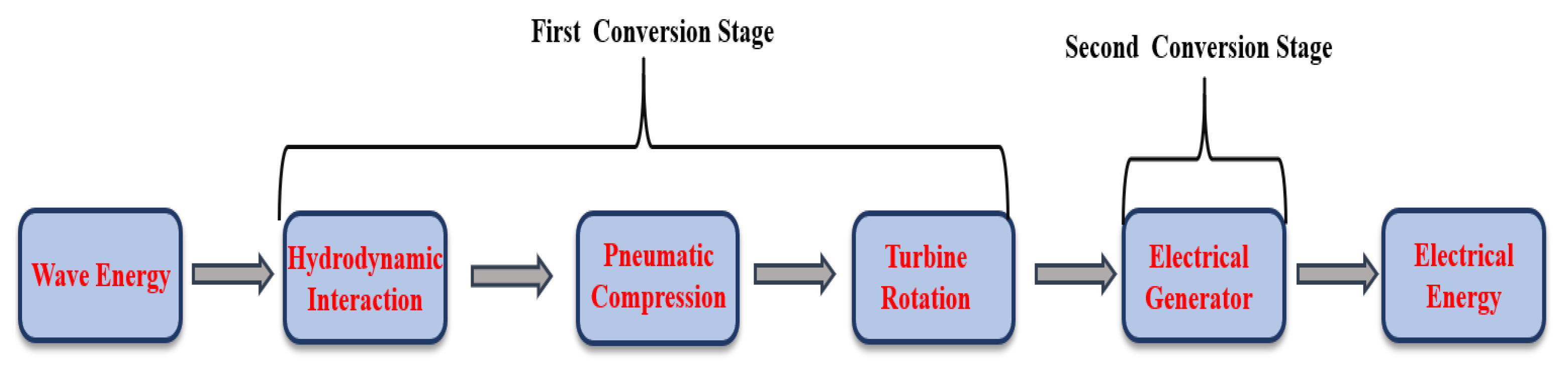
2. OWC Technology
- Incorporation into breakwaters along the shoreline: This is a widely adopted model that reduces deployment and maintenance costs.
- Nearshore deployment: They can be utilized in the form of multiple floating OWCs.
- Offshore utilization: They can be incorporated into buoys and floating constructions.
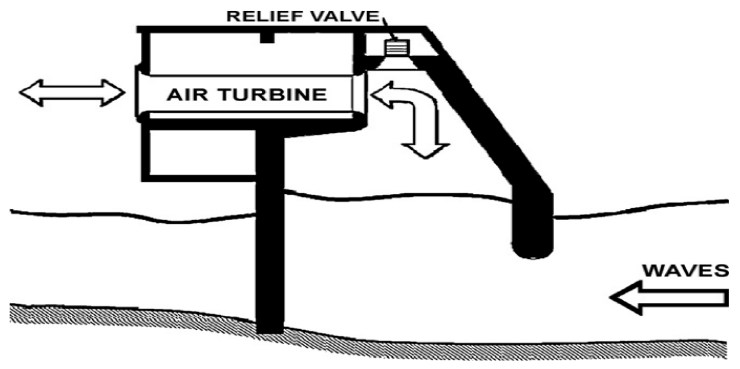
2.1. Fixed OWC Structure
2.2. Floating OWC Structure
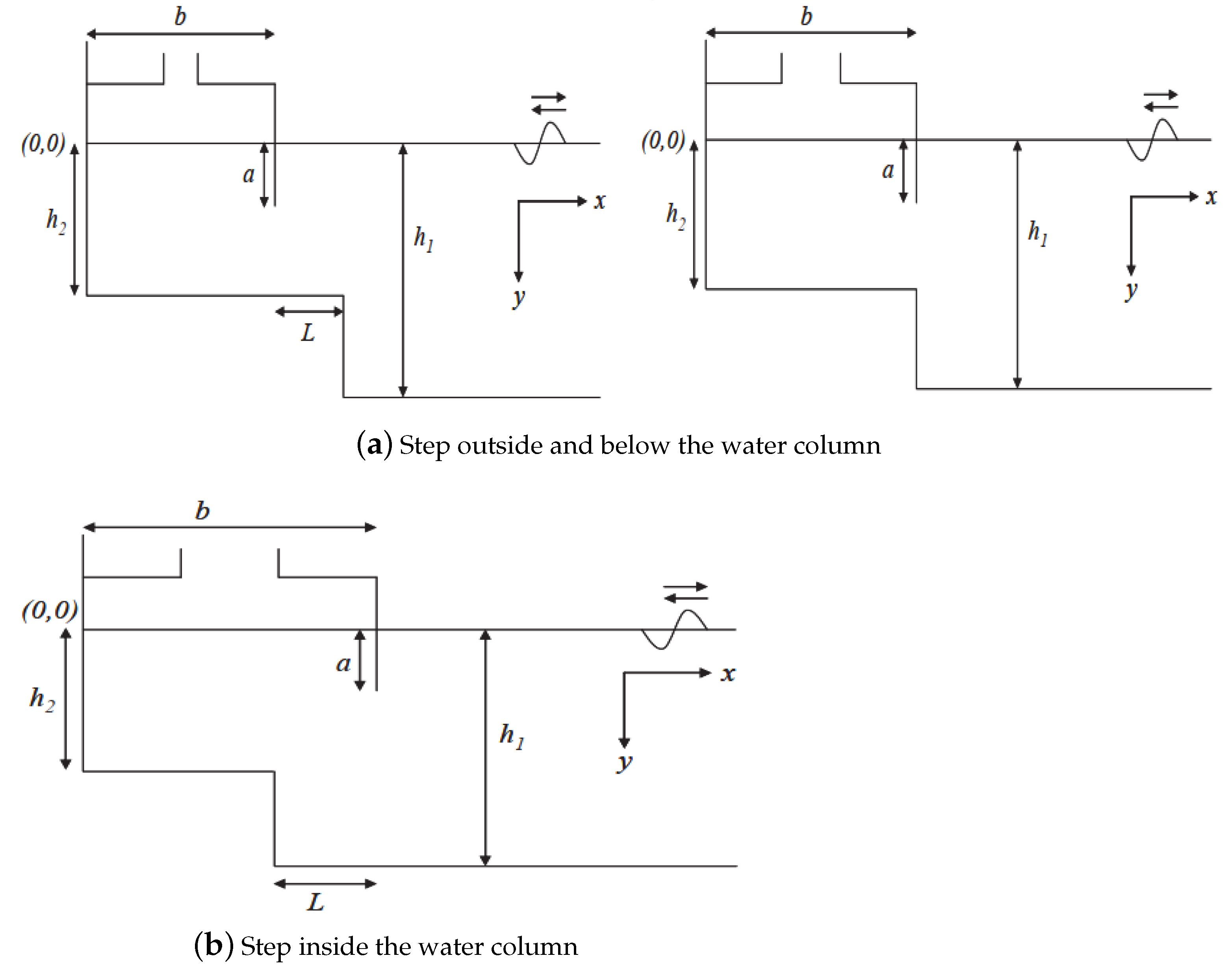
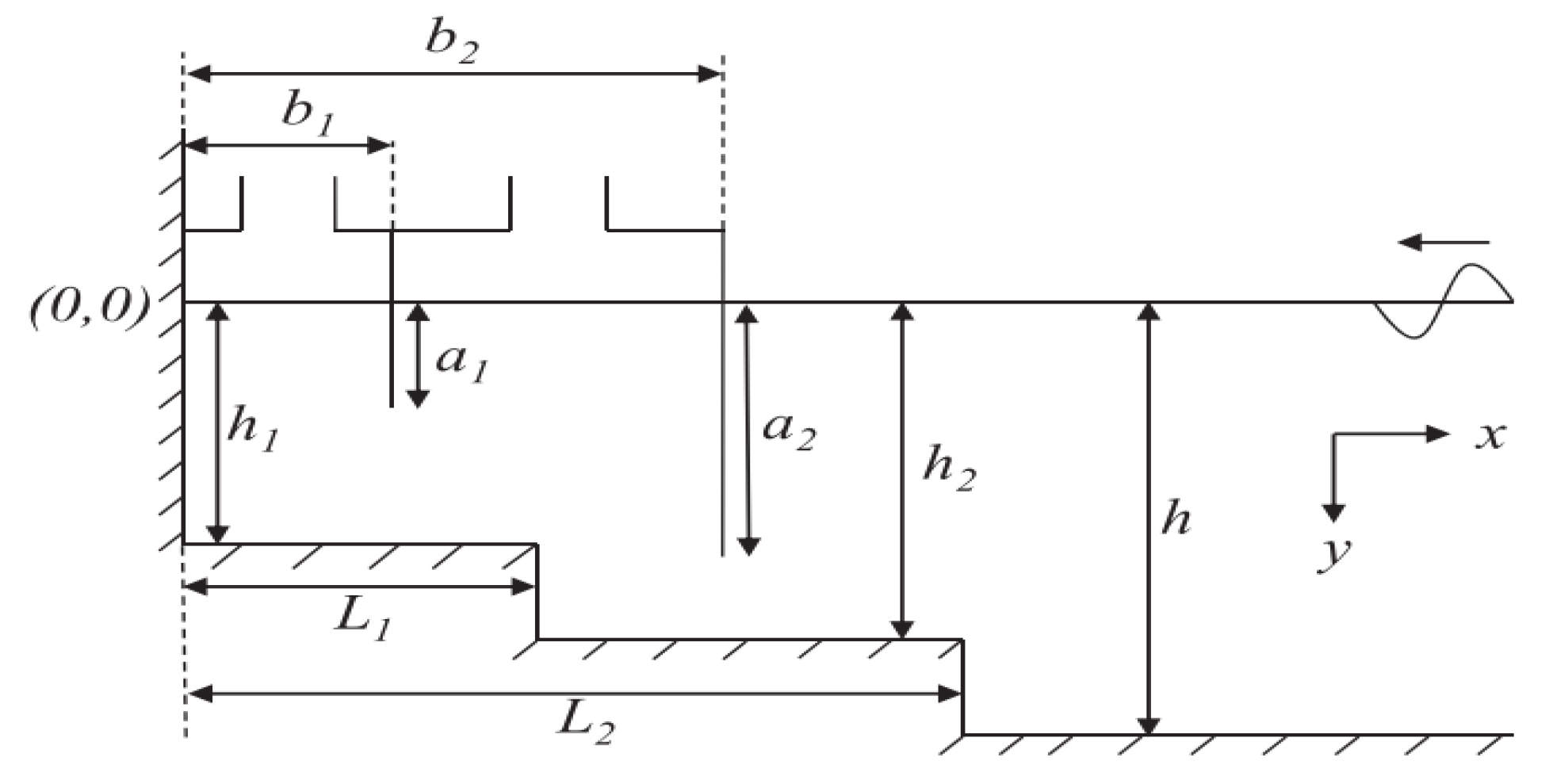
3. Hydrodynamics of OWC
4. Recent Sea-Tested OWC Prototypes and Plants
5. Computational Fluid Dynamic (CFD)
6. Conclusions
Author Contributions
Funding
Institutional Review Board Statement
Informed Consent Statement
Data Availability Statement
Acknowledgments
Conflicts of Interest
References
- Ross, D. Power from the Waves. Annu. Rev. Fluid Mech. 1995, 13, 157–187. [Google Scholar]
- McCormick, M.E. Ocean Wave Energy Conversion; Courier Corporation: North Chelmsford, MA, USA, 2013. [Google Scholar]
- Shaw, R. Wave Energy—A Design Challenge; University of Liverpool, Department of Mechanical Engineering, Ellis Horwood Ltd Publishers: Chichester, UK, 1982; ISBN 0-85312-382-9. [Google Scholar]
- Charlier, R.H.; Justus, J.R. Ocean Energies: Environmental, Economic and Technological Aspects of Alternative Power Sources; Elsevier: Amsterdam, The Netherlands, 1993. [Google Scholar]
- Brooke, J. Wave Energy Conversion; Elsevier: Amsterdam, The Netherlands, 2003. [Google Scholar]
- Cruz, J. Ocean Wave Energy: Current Status and Future Prespectives; Springer Science & Business Media: Berlin/Heidelberg, Germany, 2007. [Google Scholar]
- Thorpe, T. A Brief Review of Wave Energy: A Report Produced for the UK; ETSU-R120, May; Department of Trade and Industry: London, UK, 1999. [Google Scholar]
- WaveNet. Results from the Work of the European Thematic Network on Wave Energy. 2003. Available online: https://cordis.europa.eu/docs/projects/files/ERK5/ERK5-CT-1999-20001/66682851-6_en.pdf (accessed on 9 February 2024).
- Salter, S.H. World progress in wave energy—1988. Int. J. Ambient. Energy 1989, 10, 3–24. [Google Scholar] [CrossRef]
- Thorpe, T. An overview of wave energy technologies: Status, performance and costs. In Wave Power: Moving Towards Commercial Viability; Wiley: Hoboken, NJ, USA, 1999; Volume 26, pp. 50–120. [Google Scholar]
- Clément, A.; McCullen, P.; Falcão, A.; Fiorentino, A.; Gardner, F.; Hammarlund, K.; Lemonis, G.; Lewis, T.; Nielsen, K.; Petroncini, S.; et al. Wave energy in Europe: Current status and perspectives. Renew. Sustain. Energy Rev. 2002, 6, 405–431. [Google Scholar] [CrossRef]
- Falcão, A.d.O. First-generation wave power plants: Current status and R&D requirements. In Proceedings of the International Conference on Offshore Mechanics and Arctic Engineering, Cancun, Mexico, 8–13 June 2003; Volume 36835, pp. 723–731. [Google Scholar]
- Falnes, J. A review of wave-energy extraction. Mar. Struct. 2007, 20, 185–201. [Google Scholar] [CrossRef]
- Masuda, Y. Wave-Activated Generator; International College on the Expositions of the Oceans (Transaction): Bordeaux, France, 1971. [Google Scholar]
- Masuda, Y. Experimental full-scale results of wave power machine Kaimei in 1978. In Proceedings of the First Symposium Wave Energy Utilization, Gothenburg, Sweden, 30 October–1 November 1979; pp. 349–363. [Google Scholar]
- Salter, S.H. Wave Power. Nature 1974, 249, 720–724. [Google Scholar] [CrossRef]
- Grove-Palmer, C. Wave energy in the United Kingdom: A review of the programme June 1975–March 1982. In Proceedings of the Second International Symposium on Wave Energy Utilization (Trondheim), Trondheim, Norway, 22–24 June 1982. [Google Scholar]
- Whittaker, T.; Raghunathan, S. Islay European Shoreline Wave Power Station. In Proceedings of the First European Wave Energy Symposium, Edinburgh, Scotland, 21–24 July 1993; pp. 21–24. [Google Scholar]
- Ohneda, H.; Igarashi, S.; Shinbo, O.; Sekihara, S.; Suzuki, K.; Kubota, H.; Morita, H. Construction procedure of a wave power extracting caisson breakwater. In Proceedings of the 3rd Symposium on Ocean Energy Utilization, Tokyo, Japan, 22–23 January 1991; pp. 171–179. [Google Scholar]
- Ravindran, M.; Koola, P.M. Energy from sea waves—The Indian wave energy programme. Curr. Sci. 1991, 60, 676–680. [Google Scholar]
- Falcão, A.F.d.O. Wave energy utilization: A review of the technologies. Renew. Sustain. Energy Rev. 2010, 14, 899–918. [Google Scholar] [CrossRef]
- Xu, S.; Wang, S.; Soares, C.G. Review of mooring design for floating wave energy converters. Renew. Sustain. Energy Rev. 2019, 111, 595–621. [Google Scholar] [CrossRef]
- Heath, T. A review of oscillating water columns. Phil. Trans. R. Soc. A 2012, 370, 235–245. [Google Scholar] [CrossRef] [PubMed]
- Evans, D.; Porter, R. Hydrodynamic characteristics of an oscillating water column device. Appl. Ocean. Res. 1995, 17, 155–164. [Google Scholar] [CrossRef]
- Deng, Z.; Huang, Z.; Law, A.W. Wave power extraction by an axisymmetric oscillating-water-column converter supported by a coaxial tube-sector-shaped structure. Appl. Ocean. Res. 2013, 42, 114–123. [Google Scholar] [CrossRef]
- Porter, R.; Zheng, S.; Greaves, D. Extending limits for wave power absorption by axisymmetric devices. J. Fluid Mech. 2021, 924. [Google Scholar] [CrossRef]
- Elhanafi, A.; Fleming, A.; Macfarlane, G.; Leong, Z. Numerical energy balance analysis for an onshore oscillating water column—Wave energy converter. Energy 2016, 116, 539–557. [Google Scholar] [CrossRef]
- Michele, S.; Zheng, S.; Greaves, D. Wave energy extraction from a floating flexible circular plate. Ocean. Eng. 2022, 245, 110275. [Google Scholar] [CrossRef]
- Wu, J.; Qin, L.; Chen, N.; Qian, C.; Zheng, S. Investigation on a spring-integrated mechanical power take-off system for wave energy conversion purpose. Energy 2022, 245, 123318. [Google Scholar] [CrossRef]
- Hamamoto, T.; Tanaka, Y. Coupled free vibrational characteristics of artificial floating islands. Part 1.; Fluid-structure interaction analysis of floating elastic circular plate. Fuyushiki kaiyo jinkoto no rensei jiyu shindo tokusei. 1.; Fuyu dansei enban no ryutai-kozobutsu sogo sayo kaiseki. Nippon Kenchiku Gakkai Kozokei Ronbun Hokokushu (J. Struct. Constr. Eng.) 1992, 438, 165–177. [Google Scholar]
- Montiel, F.; Bennetts, L.; Squire, V.; Bonnefoy, F.; Ferrant, P. Hydroelastic response of floating elastic discs to regular waves. Part 2. Modal analysis. J. Fluid Mech. 2013, 723, 629–652. [Google Scholar] [CrossRef]
- Das, S.; Sahoo, T. Hydroelastic analysis of very large floating structure over viscoelastic bed. Meccanica 2017, 52, 1871–1887. [Google Scholar] [CrossRef]
- Energy, A. Oscillating water column wave energy converter evaluation report. In The Carbon Trust, Marine Energy Challenge; Elsevier: Amsterdam, The Netherlands, 2005; pp. 1–196. [Google Scholar]
- Zheng, S.; Antonini, A.; Zhang, Y.; Greaves, D.; Miles, J.; Iglesias, G. Wave power extraction from multiple oscillating water columns along a straight coast. J. Fluid Mech. 2019, 878, 445–480. [Google Scholar] [CrossRef]
- Lehmann, M.; Karimpour, F.; Goudey, C.A.; Jacobson, P.T.; Alam, M.R. Ocean wave energy in the United States: Current status and future perspectives. Renew. Sustain. Energy Rev. 2017, 74, 1300–1313. [Google Scholar] [CrossRef]
- Qiao, D.; Haider, R.; Yan, J.; Ning, D.; Li, B. Review of wave energy converter and design of mooring system. Sustainability 2020, 12, 8251. [Google Scholar] [CrossRef]
- Setoguchi, T.; Takao, M. Current status of self rectifying air turbines for wave energy conversion. Energy Convers. Manag. 2006, 47, 2382–2396. [Google Scholar] [CrossRef]
- Doyle, S.; Aggidis, G.A. Development of multi-oscillating water columns as wave energy converters. Renew. Sustain. Energy Rev. 2019, 107, 75–86. [Google Scholar] [CrossRef]
- Delmonte, N.; Barater, D.; Giuliani, F.; Cova, P.; Buticchi, G. Oscillating water column power conversion: A technology review. In Proceedings of the 2014 IEEE Energy Conversion Congress and Exposition (ECCE), IEEE, Pittsburgh, PA, USA, 14–18 September 2014; pp. 1852–1859. [Google Scholar]
- Lye, J.L.; Brown, D.T.; Johnson, F. An investigation into the non-linear effects resulting from air cushions in the Orecon oscillating water column (OWC) device. In Proceedings of the International Conference on Offshore Mechanics and Arctic Engineering, Osaka, Japan, 21–26 June 2009; Volume 43444, pp. 779–789. [Google Scholar]
- Dorrell, D.G.; Hsieh, M.F.; Lin, C.C. A multichamber oscillating water column using cascaded savonius turbines. IEEE Trans. Ind. Appl. 2010, 46, 2372–2380. [Google Scholar] [CrossRef]
- Falcão, A.F.; Henriques, J.C.; Gato, L.M. Self-rectifying air turbines for wave energy conversion: A comparative analysis. Renew. Sustain. Energy Rev. 2018, 91, 1231–1241. [Google Scholar] [CrossRef]
- Count, B.; Evans, D. The influence of projecting sidewalls on the hydrodynamic performance of wave-energy devices. J. Fluid Mech. 1984, 145, 361–376. [Google Scholar] [CrossRef]
- Alcorn, R.; Hunter, S.; Signorelli, C.; Obeyesekera, R.; Finnigan, T.; Denniss, T. Results of the testing of the Energetech wave energy plant at Port Kembla. Energeth Rep. 2005, 5, 44. [Google Scholar]
- Basmat, A.; Denniss, T.; Finnigan, T. Diffraction of linear water waves on a parabolic wall: Small parameter approach. In Proceedings of the ISOPE International Ocean and Polar Engineering Conference, ISOPE, Honolulu, HI, USA, 25–30 May 2003; p. ISOPE–I. [Google Scholar]
- Martins, E.; Carrilho, L.; Neumann, F.; Ramos, F.S.; Justino, P.A.; Gato, L.; Trigo, L. Ceodouro project: Overall design of an OWC in the new OPorto break water. In Proceedings of the Conference: 6. EWTEC- European Wave and Tidal Energy Conference, Glasgow, UK, 29 August–2 September 2005. [Google Scholar]
- Torre-Enciso, Y.; Ortubia, I.; De Aguileta, L.L.; Marqués, J. Mutriku wave power plant: From the thinking out to the reality. In Proceedings of the 8th European wave and tidal Energy Conference, Uppsala, Sweden, 7–10 September 2009; Volume 710, pp. 319–329. [Google Scholar]
- Boccotti, P. Caisson breakwaters embodying an OWC with a small opening—Part I: Theory. Ocean. Eng. 2007, 34, 806–819. [Google Scholar] [CrossRef]
- Boccotti, P.; Filianoti, P.; Fiamma, V.; Arena, F. Caisson breakwaters embodying an OWC with a small opening—Part II: A small-scale field experiment. Ocean. Eng. 2007, 34, 820–841. [Google Scholar] [CrossRef]
- Masuda, Y.; McCormick, M.E. Experiences in pneumatic wave energy conversion in Japan. In Proceedings of the Coastal Engineering 1986, ASCE, Reston, VA, USA, 9–11 March 1986; pp. 1–33. [Google Scholar]
- Masuda, Y.; Xianguang, L.; Xiangfan, G. High performance of cylinder float backward bent duct buoy (BBDB) and its use in European seas. In Proceedings of the (First) European Wave Energy Symposium, Enburgh, Scotland, 21–24 July 1993; pp. 323–337. [Google Scholar]
- Masuda, Y.; Kimura, H.; Liang, X.; Gao, X.; Mogensen, R.; Anderson, T. Regarding BBDB wave power generation plant. In Proceedings of the 2nd European Wave Power Conference, Lisbon, Portugal, 8–10 November 1995; pp. 69–76. [Google Scholar]
- Washio, Y.; Osawa, H.; Nagata, Y.; Fujii, F.; Furuyama, H.; Fujita, T. The offshore floating type wave power device “Mighty Whale”: Open sea tests. In Proceedings of the ISOPE International Ocean and Polar Engineering Conference, ISOPE, Seattle, WA, USA, 27 May–2 June 2000; p. ISOPE–I. [Google Scholar]
- Evans, D. A theory for wave-power absorption by oscillating bodies. J. Fluid Mech. 1976, 77, 1–25. [Google Scholar] [CrossRef]
- Sarmento, A.J.; Falcão, A.d.O. Wave generation by an oscillating surface-pressure and its application in wave-energy extraction. J. Fluid Mech. 1985, 150, 467–485. [Google Scholar] [CrossRef]
- Falnes, J.; McIver, P. Surface wave interactions with systems of oscillating bodies and pressure distributions. Appl. Ocean. Res. 1985, 7, 225–234. [Google Scholar] [CrossRef]
- Konispoliatis, D.N. Performance of an array of oscillating water column devices in front of a fixed vertical breakwater. J. Mar. Sci. Eng. 2020, 8, 912. [Google Scholar] [CrossRef]
- Konispoliatis, D.N.; Mavrakos, S.A. Hydrodynamic efficiency of a wave energy converter in front of an orthogonal breakwater. J. Mar. Sci. Eng. 2021, 9, 94. [Google Scholar] [CrossRef]
- Pols, A.; Gubesch, E.; Abdussamie, N.; Penesis, I.; Chin, C. Mooring analysis of a floating OWC wave energy converter. J. Mar. Sci. Eng. 2021, 9, 228. [Google Scholar] [CrossRef]
- Mohapatra, P.; Bhattacharyya, A.; Sahoo, T. Performance of a floating oscillating water column wave energy converter over a sloping bed. Ships Offshore Struct. 2021, 16, 659–669. [Google Scholar] [CrossRef]
- Lovas, S.; Mei, C.C.; Liu, Y. Oscillating water column at a coastal corner for wave power extraction. Appl. Ocean. Res. 2010, 32, 267–283. [Google Scholar] [CrossRef]
- Rezanejad, K.; Bhattacharjee, J.; Soares, C.G. Stepped sea bottom effects on the efficiency of nearshore oscillating water column device. Ocean. Eng. 2013, 70, 25–38. [Google Scholar] [CrossRef]
- Wang, C.; Zheng, S.; Zhang, Y. A heaving system with two separated oscillating water column units for wave energy conversion. Phys. Fluids 2022, 34, 047103. [Google Scholar] [CrossRef]
- Renzi, E. Hydroelectromechanical modelling of a piezoelectric wave energy converter. Proc. R. Soc. Math. Phys. Eng. Sci. 2016, 472, 20160715. [Google Scholar] [CrossRef]
- Nader, J.R.; Zhu, S.P.; Cooper, P.; Stappenbelt, B. A finite-element study of the efficiency of arrays of oscillating water column wave energy converters. Ocean. Eng. 2012, 43, 72–81. [Google Scholar] [CrossRef]
- Zheng, S.; Meylan, M.; Greaves, D.; Iglesias, G. Water-wave interaction with submerged porous elastic disks. Phys. Fluids 2020, 32, 047106. [Google Scholar] [CrossRef]
- Zheng, S.; Meylan, M.H.; Zhu, G.; Greaves, D.; Iglesias, G. Hydroelastic interaction between water waves and an array of circular floating porous elastic plates. J. Fluid Mech. 2020, 900, A20. [Google Scholar] [CrossRef]
- Trivedi, K.; Koley, S. Performance of a hybrid wave energy converter device consisting of a piezoelectric plate and oscillating water column device placed over an undulated seabed. Appl. Energy 2023, 333, 120627. [Google Scholar] [CrossRef]
- Zheng, S.; Phillips, J.W.; Hann, M.; Greaves, D. Mathematical modelling of a floating Clam-type wave energy converter. Renew. Energy 2023, 210, 280–294. [Google Scholar] [CrossRef]
- Wang, C.; Deng, Z.; Wang, P. Numerical investigation of dual-owc-devices system composed by offshore and onshore unit. In International Conference on Asian and Pacific Coasts; Springer: Berlin/Heidelberg, Germany, 2019; pp. 107–114. [Google Scholar]
- He, G.; Luan, Z.; Jin, R.; Zhang, W.; Wang, W.; Zhang, Z.; Jing, P.; Liu, P. Numerical and experimental study on absorber-type wave energy converters concentrically arranged on an octagonal platform. Renew. Energy 2022, 188, 504–523. [Google Scholar] [CrossRef]
- McIver, P.; Evans, D. Approximate theory for the performance of a number of wave-energy devices set into a reflecting wall. Appl. Ocean Res. 1988, 10, 58–65. [Google Scholar] [CrossRef]
- Thiruvenkatasamy, K.; Neelamani, S. On the efficiency of wave energy caissons in array. Appl. Ocean. Res. 1997, 19, 61–72. [Google Scholar] [CrossRef]
- Falcão, A.d.O. Wave-power absorption by a periodic linear array of oscillating water columns. Ocean. Eng. 2002, 29, 1163–1186. [Google Scholar] [CrossRef]
- Rezanejad, K.; Bhattacharjee, J.; Soares, C.G. Analytical and numerical study of dual-chamber oscillating water columns on stepped bottom. Renew. Energy 2015, 75, 272–282. [Google Scholar] [CrossRef]
- Konispoliatis, D.; Mavrakos, S. Hydrodynamic analysis of an array of interacting free-floating oscillating water column (OWC’s) devices. Ocean. Eng. 2016, 111, 179–197. [Google Scholar] [CrossRef]
- Zheng, S.; Zhang, Y.; Iglesias, G. Wave–structure interaction in hybrid wave farms. J. Fluids Struct. 2018, 83, 386–412. [Google Scholar] [CrossRef]
- Zheng, S.; Zhang, Y. Theoretical modelling of a new hybrid wave energy converter in regular waves. Renew. Energy 2018, 128, 125–141. [Google Scholar] [CrossRef]
- Mia, M.R.; Zhao, M.; Wu, H.; Dhamelia, V.; Hu, P. Hydrodynamic Performance of a Floating Offshore Oscillating Water Column Wave Energy Converter. J. Mar. Sci. Eng. 2022, 10, 1551. [Google Scholar] [CrossRef]
- Zhou, Y.; Ning, D.; Liang, D.; Qiao, D. Nonlinear wave loads on an offshore oscillating-water-column wave energy converter array. Appl. Ocean. Res. 2022, 118, 103003. [Google Scholar] [CrossRef]
- Romolo, A.; Timpano, B.; Laface, V.; Fiamma, V.; Arena, F. Experimental Investigation of Wave Loads on U-OWC Breakwater. J. Mar. Sci. Eng. 2023, 11, 19. [Google Scholar] [CrossRef]
- Cannata, G.; Simone, M.; Gallerano, F. Numerical Investigation into the Performance of an OWC Device under Regular and Irregular Waves. J. Mar. Sci. Eng. 2023, 11, 735. [Google Scholar] [CrossRef]
- Gouaud, F.; Rey, V.; Piazzola, J.; Van Hooff, R. Experimental study of the hydrodynamic performance of an onshore wave power device in the presence of an underwater mound. Coast. Eng. 2010, 57, 996–1005. [Google Scholar] [CrossRef]
- Ashlin, S.J.; Sundar, V.; Sannasiraj, S. Effects of bottom profile of an oscillating water column device on its hydrodynamic characteristics. Renew. Energy 2016, 96, 341–353. [Google Scholar] [CrossRef]
- Rezanejad, K.; Soares, C.G. Enhancing the primary efficiency of an oscillating water column wave energy converter based on a dual-mass system analogy. Renew. Energy 2018, 123, 730–747. [Google Scholar] [CrossRef]
- Rezanejad, K.; Souto-Iglesias, A.; Soares, C.G. Experimental investigation on the hydrodynamic performance of an L-shaped duct oscillating water column wave energy converter. Ocean. Eng. 2019, 173, 388–398. [Google Scholar] [CrossRef]
- Zabihi, M.; Mazaheri, S.; Namin, M.M. Experimental hydrodynamic investigation of a fixed offshore Oscillating Water Column device. Appl. Ocean. Res. 2019, 85, 20–33. [Google Scholar] [CrossRef]
- Zhang, Y.; Li, M.; Zhao, X.; Chen, L. The effect of the coastal reflection on the performance of a floating breakwater-WEC system. Appl. Ocean. Res. 2020, 100, 102117. [Google Scholar] [CrossRef]
- Chen, J.; Wen, H.; Wang, Y.; Ren, B. Experimental investigation of an annular sector OWC device incorporated into a dual cylindrical caisson breakwater. Energy 2020, 211, 118681. [Google Scholar] [CrossRef]
- Falcão, A. Overview on oscillating water column devices. In Floating Offshore Energy Devices: GREENER; Materials Research Forum LLC.: Millersville, PA, USA, 2022; Volume 20. [Google Scholar] [CrossRef]
- Boccotti, P. Comparison between a U-OWC and a conventional OWC. Ocean. Eng. 2007, 34, 799–805. [Google Scholar] [CrossRef]
- Gayathri, R.; Chang, J.Y.; Tsai, C.C. Wave power extraction from slanted oscillating water columns in the presence of an array of arbitrary trenches. Phys. Fluids 2023, 35, 97105. [Google Scholar] [CrossRef]
- Horko, M. CFD Optimisation of an Oscillating Water Column Wave Energy Converter. Ph.D. Thesis, University of Western Australia, Crawley, WA, Australia, 2007. [Google Scholar]
- Iturrioz, A.; Guanche, R.; Lara, J.; Vidal, C.; Losada, I. Validation of OpenFOAM® for oscillating water column three-dimensional modeling. Ocean. Eng. 2015, 107, 222–236. [Google Scholar] [CrossRef]
- Xu, C.; Huang, Z. Three-dimensional CFD simulation of a circular OWC with a nonlinear power-takeoff: Model validation and a discussion on resonant sloshing inside the pneumatic chamber. Ocean. Eng. 2019, 176, 184–198. [Google Scholar] [CrossRef]
- Shalby, M.; Elhanafi, A.; Walker, P.; Dorrell, D.G. CFD modelling of a small–scale fixed multi–chamber OWC device. Appl. Ocean. Res. 2019, 88, 37–47. [Google Scholar] [CrossRef]
- Goeijenbier, B.; Bricker, J.; Antonini, A.; Malara, G.; Hendriks, M.; van der Ham, H. Structural Optimisation and Behaviour of the Breakwater Integrated Oscillating Water Column Device: A combined 3D CFD and Structural FEM Analysis. J. Coast. Hydraul. Struct. 2021, 1. [Google Scholar]
- Cabral, T.; Clemente, D.; Rosa-Santos, P.; Taveira-Pinto, F.; Morais, T.; Belga, F.; Cestaro, H. Performance assessment of a hybrid wave energy converter integrated into a harbor breakwater. Energies 2020, 13, 236. [Google Scholar] [CrossRef]
- Wang, C.; Zhang, Y. Hydrodynamic performance of an offshore Oscillating Water Column device mounted over an immersed horizontal plate: A numerical study. Energy 2021, 222, 119964. [Google Scholar] [CrossRef]


Disclaimer/Publisher’s Note: The statements, opinions and data contained in all publications are solely those of the individual author(s) and contributor(s) and not of MDPI and/or the editor(s). MDPI and/or the editor(s) disclaim responsibility for any injury to people or property resulting from any ideas, methods, instructions or products referred to in the content. |
© 2024 by the authors. Licensee MDPI, Basel, Switzerland. This article is an open access article distributed under the terms and conditions of the Creative Commons Attribution (CC BY) license (https://creativecommons.org/licenses/by/4.0/).
Share and Cite
Gayathri, R.; Chang, J.-Y.; Tsai, C.-C.; Hsu, T.-W. Wave Energy Conversion through Oscillating Water Columns: A Review. J. Mar. Sci. Eng. 2024, 12, 342. https://doi.org/10.3390/jmse12020342
Gayathri R, Chang J-Y, Tsai C-C, Hsu T-W. Wave Energy Conversion through Oscillating Water Columns: A Review. Journal of Marine Science and Engineering. 2024; 12(2):342. https://doi.org/10.3390/jmse12020342
Chicago/Turabian StyleGayathri, R., Jen-Yi Chang, Chia-Cheng Tsai, and Tai-Wen Hsu. 2024. "Wave Energy Conversion through Oscillating Water Columns: A Review" Journal of Marine Science and Engineering 12, no. 2: 342. https://doi.org/10.3390/jmse12020342