Article

Pile Driving and the Setup Effect and Underlying Mechanism for Different Pile Types in Calcareous Sand Foundations

1
School of Earth Sciences and Engineering, Sun Yat-sen University, Zhuhai 519082, China
2
Southern Marine Science and Engineering Guangdong Laboratory (Zhuhai), Zhuhai 519082, China
3
Research Center of Coastal and Urban Geotechnical Engineering, College of Civil Engineering and Architecture, Zhejiang University, Zijingang Compus, Hangzhou 310058, China
4
Guangzhou Metro Design and Research Institute Co., Ltd., Guangzhou 510010, China
*
Author to whom correspondence should be addressed.
J. Mar. Sci. Eng. 2024, 12(1), 133; https://doi.org/10.3390/jmse12010133
Submission received: 16 October 2023 / Revised: 14 December 2023 / Accepted: 5 January 2024 / Published: 9 January 2024
(This article belongs to the Special Issue Engineering Properties of Marine Soils and Offshore Foundations)

Abstract

:
The mechanical response and deformation characteristics in calcareous sand foundations during pile driving and setup were studied using model tests combined with the technical methods of tactile pressure sensors and close-range photogrammetry. Different types of piles were considered, including a pipe pile, square pile and semi-closed steel pipe pile. The test results show that during pile driving, the pile tip resistance of different piles increases with an increase in the pile insertion depth, and an obvious fluctuation is also obtained due to the particle breakage of the calcareous sand and energy dissipation. Different degrees of particle breakage generated by different type piles make the internal stress variations different, as with the pile tip resistance. The pile tip resistance of model pile A, which simulates a pipe pile, is the highest, followed by model pile B, the simulated square pile. Model pile C, which simulates a semi-closed steel pipe pile, has the smallest pile tip resistance because its particle breakage is the most obvious and the pile tip energy cannot be continuously accumulated. The induced deformation such as sag or uplift on the surface and the associated influence range for the calcareous sand foundation are the smallest for model pile C, followed by model pile B and then model pile A. Model pile A has the most obvious pile driving effect. During the pile setup process after piling, the increase in the total internal stress of model pile B is the largest, and the improvement of the potential bearing capacity is the most obvious, followed by model pile A and model pile C. During the pile setup, the induced uplift deformation in pile driving is recovered and the potential bearing capacity increases due the redistribution and uniformity of the vertical and radial stress distributions in the calcareous sand foundation. Considering the potential bearing capacity of different model piles, the influence range of pile driving, foundation deformation and the pile setup effect, it is suggested to use a pointed square pile corresponding to model pile B in pile engineering in calcareous sand foundations.

1. Introduction

Calcareous sand is widely distributed between 30 degrees south latitude and 30 degrees north latitude, covering many countries and regions [1], especially the South China Sea Islands, most of which are coral reefs covered with thick layers of calcareous sand [2,3]. These islands and their surrounding areas are rich in marine mineral resources and also have an important strategic position in the social economy, national defense and scientific research. With an increase in the scale and quantity of island and reef engineering, engineering problems are becoming more and more prominent [4].
Calcareous sand is different from siliceous sand and characterized by a high porosity ratio [5,6], prominent edges [7,8] and easy breakage [9,10]. Its engineering mechanical properties are so complex and special that the research results of and engineering experience with traditional soil materials cannot be directly applied to calcareous sand [11,12,13,14,15,16,17,18,19]. As one of the most common foundation forms, it is of great significance to study the application of pile foundations to calcareous sand, especially to explore the effect of pile driving and engineering mechanical properties in calcareous sand foundations. Up to now, previous studies have mostly focused on the macroscopic mechanical properties of pile foundations in calcareous sand [20,21,22,23,24], and have mainly considered the effects of the calcareous sand particle size distribution [25], cementation degree, pile length [26,27] and load conditions [28,29,30,31,32] on the bearing characteristics of piles. McDowell et al. [33], using small-size model tests on the bearing characteristics of a single pile, pointed out that the peek resistance of a single pile is a strong function of the initial particle size distribution, and the peak resistance in well-graded calcareous sand is greater than that in uniformly graded calcareous sand. In terms of the influence of the cementation degree, Houlsby et al. [34] proposed a functional relationship between the ratio of the cemented layer thickness to the pile diameter and the ultimate bearing capacity. Wang et al. [35], using a model test of jacked piles, pointed out that the jacking pile pressure increases nonlinearly with the increase in pile length, in which the radial stress of the piles gradually converges with passive Earth pressure with the increase in the pile length. By analyzing the datasets of over 37 real projects on super-large and long piles, Thien et al. [36] pointed out that pile length has a certain influence on the pile tip resistance, and they are positively correlated.
As for the influence of the load conditions, Al-Douri et al. [37] pointed out that under cyclic axial loads with the same amplitude, the total displacement increased with an increase in load level and the number of cycles. Among them, Roozbeh et al. [38] believe that asymmetric two-way loading is the most destructive type of cyclic loading. The research by Wang et al. [39] showed that the shaft resistance gradually decreased during dynamic loading, and the ultimate pile tip resistance decreased with an increase in the dynamic load ratio; furthermore, the strength of the pile–sand interface was weakened under dynamic loading, and the calcareous sand particles were broken seriously, resulting in shear shrinkage.
Considering the distribution of the pile foundation and whether the pile ends are closed or not, Jiang [40,41] and Yang et al. [42] conducted experimental studies on the single pile and pile group effects of open-ended and closed-ended piles in calcareous sand, and the results showed that the pile group effect in calcareous sand was significantly different from that in quartz sand. The bearing capacity of these piles was mainly provided by the pile tip resistance, and the mechanism of pile tip resistance and shaft resistance was also analyzed; however, they did not take a deep dive into the bearing characteristics of different pile types in calcareous sand foundations. Wan et al. [43,44] constructed experimental studies on the axial and horizontal bearing capacity of post-grouting piles in calcareous sand, pointing out that the bearing capacity of a single pile after grouting is improved, and, due to the influence of particle breakage in calcareous sand, the increase ratio of the bearing capacity after grouting in calcareous sand is higher than that of siliceous sand. Yu et al. [45], using a model test of cast-in-place concrete X-section and circular section pile groups, pointed out that under the same section area, the bearing capacity of X-section piles is much greater than that of circular section piles.
Some researchers have also analyzed the breakage of calcareous sand particles in the process of pile driving using simulations based on the discrete element method (DEM), so as to explore the mechanical response of calcareous sand and its mechanism [46,47]. However, the existing experimental studies have not revealed the mechanical characteristics and mechanism of different pile types in calcareous sand foundations. Therefore, this paper carried out pile model tests of different pile types in calcareous sand, combined with the use of the technical methods of tactile pressure sensors and close-range photogrammetry, to explore the pile driving and setup of different pile types in calcareous sand foundations, and reveal the mechanical characteristics of the whole process of pile driving.

2. Experimental Details
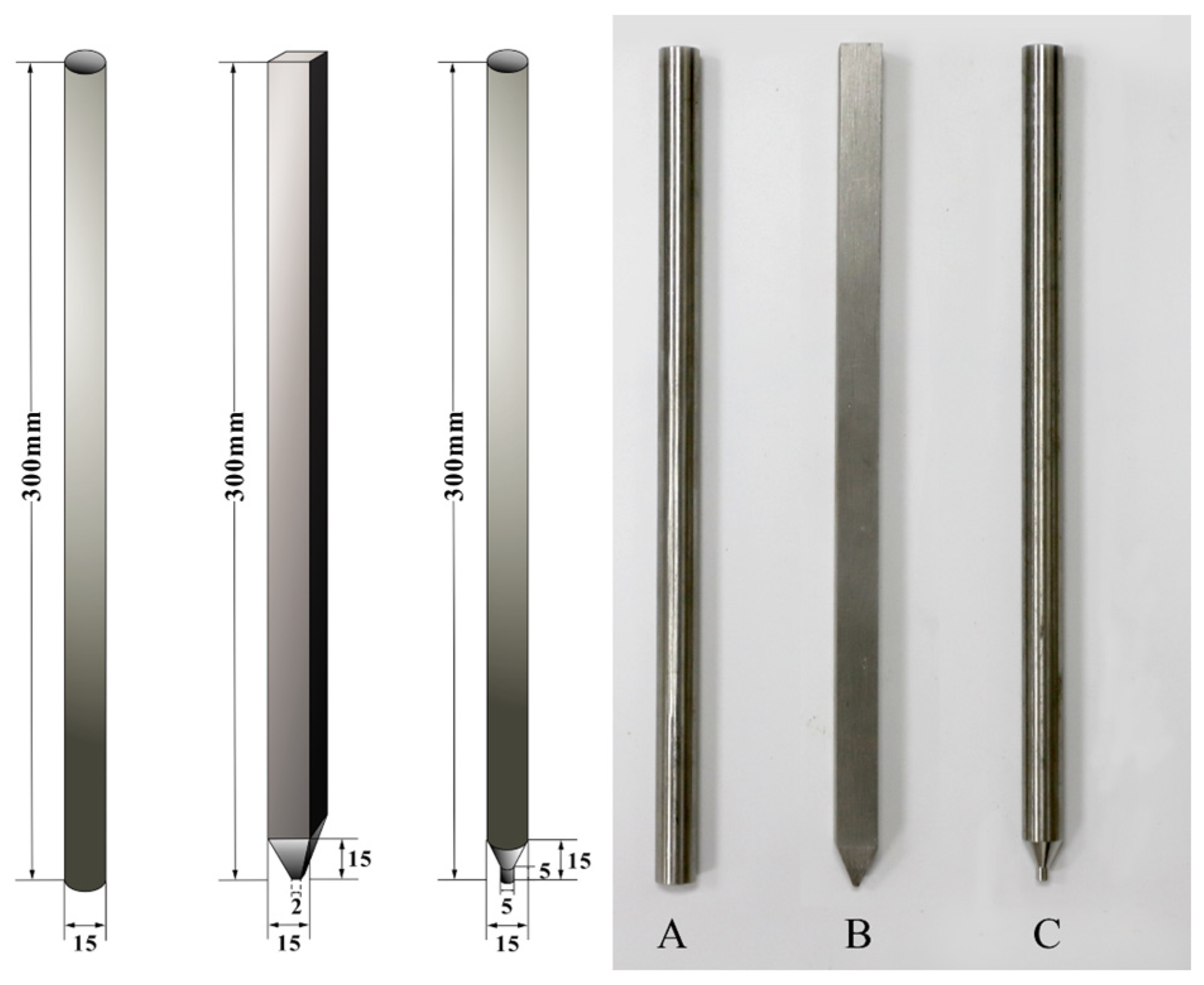
2.1. Model Piles

According to three traditional pile end shapes of precast piles, a prestressed pipe pile with a side length of Φ600 mm, a precast reinforced concrete square pile with a side length of 600 mm and a semi-closed-end steel pipe pile with a side length Φ600 mm were selected as prototypes, and reduced to small-size models with a ratio of 40:1. In the process of pile driving using a static load, whether the pile is hollow or not and whether the pile is open-ended or close-ended, there is little influence on the bearing characteristics [48]. Therefore, model piles with a solid structure are adopted to ensure the small-size model piles are rigid enough. The geometric shape and size of different model piles are shown in Figure 1. Among them, model pile A simulates the prestressed pipe pile, model pile B simulates the precast reinforced concrete square pile and model C simulates the semi-closed-end steel pipe pile.

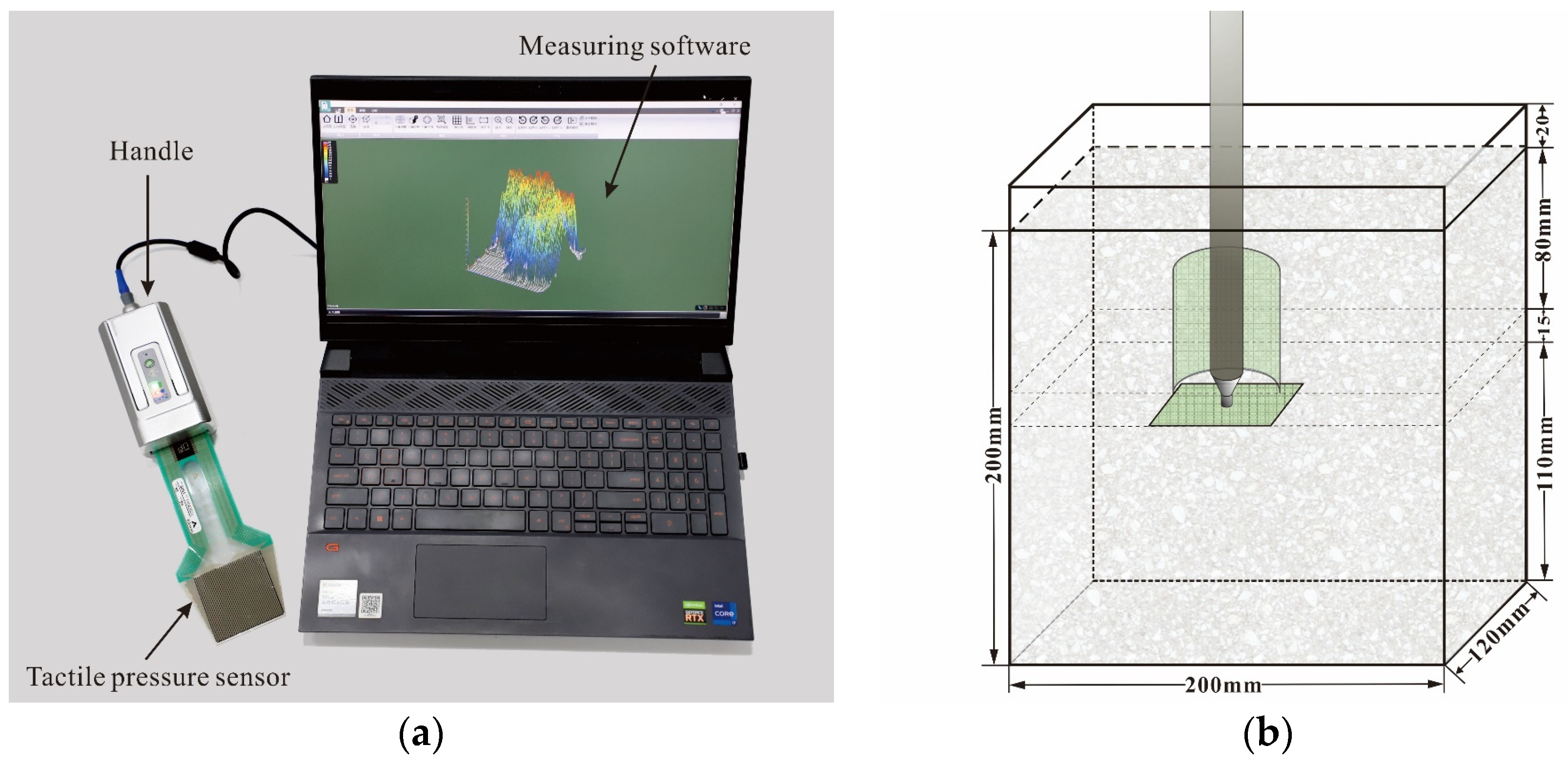
2.2. Model Box and Test Material

The model box is cubic and made of acrylic plates with a thickness of 10 mm, which have the advantage of transparency and visibility under the premise of meeting the rigidity requirements. The refraction effect of acrylic plates in different model tests is relatively consistent, which makes sure there are only small measurement errors in the comparison of particle breakage under different tests. Considering the requirements of the particle size effect, boundary effect and pile distance from the bottom of the box [49,50], the interior dimensions of the model box are designed to be 200 mm long, 120 mm wide and 220 mm high. A reduced model would affect the magnitude of the displacement and stress, which may be different from large-scale prototypes, while the underlying mechanics will not be changed.
The calcareous sand used in this paper is from an island in the South China Sea and comprises unconsolidated and loose particles. The main component of calcareous sand is calcium carbonate with a content of more than 90%. Due to its sedimentary origin and limited geological transportation, the shape of calcareous sand particles exhibits a high degree of irregularity, characterized by various shapes including flakes, blocks, strips, dendrites and others. According to the similarity theory, the influence of the particle size effect on the test results should be reduced as much as possible. Therefore, dry calcareous sand with a particle size of 2–5 mm is used as the foundation soil material for the model test, and its maximum and minimum dry densities are 1290 kg/m3 and 1180 kg/m3, respectively. The calcareous sand was divided into eight layers and laid layer by layer to the designed height of 200 mm in the model box, in which the relative density of the calcareous sand was controlled to be 0.60, and the corresponding dry density was 1240 kg/m3.

2.3. Testing Design

In order to explore the characteristics of calcareous sand foundations during pile driving and setup, tactile pressure sensors (mode PFS5051, Tekscan Inc., Norwood, MA, USA) with a measuring range of 334.74 kPa are utilized, as shown in Figure 2a. The sensing area of the sensors is 56 mm × 56 mm, and 1936 measuring points are distributed in a matrix of 44 rows and 44 columns, among which the area of a single measuring point is only 1.62 mm2. To obtain the vertical and radial stress distribution during pile driving in calcareous sand foundations, two tactile pressure sensors are deployed in the vertical and horizontal directions, as shown in Figure 2b. The horizontal tactile pressure sensor is buried 10 mm below the pile end at the maximum driving depth, that is, 110 mm away from the bottom of the model box. The circumferential tactile pressure sensor is buried around the center of the pile, about 15 mm away from the pile shaft, and the bottom of the sensor is buried 15 mm above the horizontal tactile pressure sensor, that is, 125 mm away from the bottom of the model box.
In order to simulate pile driving using a static load, the MTS electromechanical testing system (Exceed, model E45) is used to apply loading at a constant speed of 0.02 mm/s until the pile driving depth reaches 80 mm, and the stress distribution calcareous sand foundation is measured every 5 mm using the tactile pressure sensor. After the pile driving is completed, the external force on the model pile is removed, and the depth of the pile is kept at 80 mm to enter the static process, i.e., the pile setup process. The pile setup is retained for 24 h, and the stress distribution calcareous sand foundation is measured at 5 min intervals within the first hour, and then measured and photographed at time points of 90 min, 120 min, 240 min, 420 min, 540 min, 1020 min, 1260 min and 1440 min, respectively. Fixed-point photogrammetry is also carried out in front of the model box to observe the deformation and particle crushing of the calcareous sand foundation during the pile driving and setup processes.

3. Results

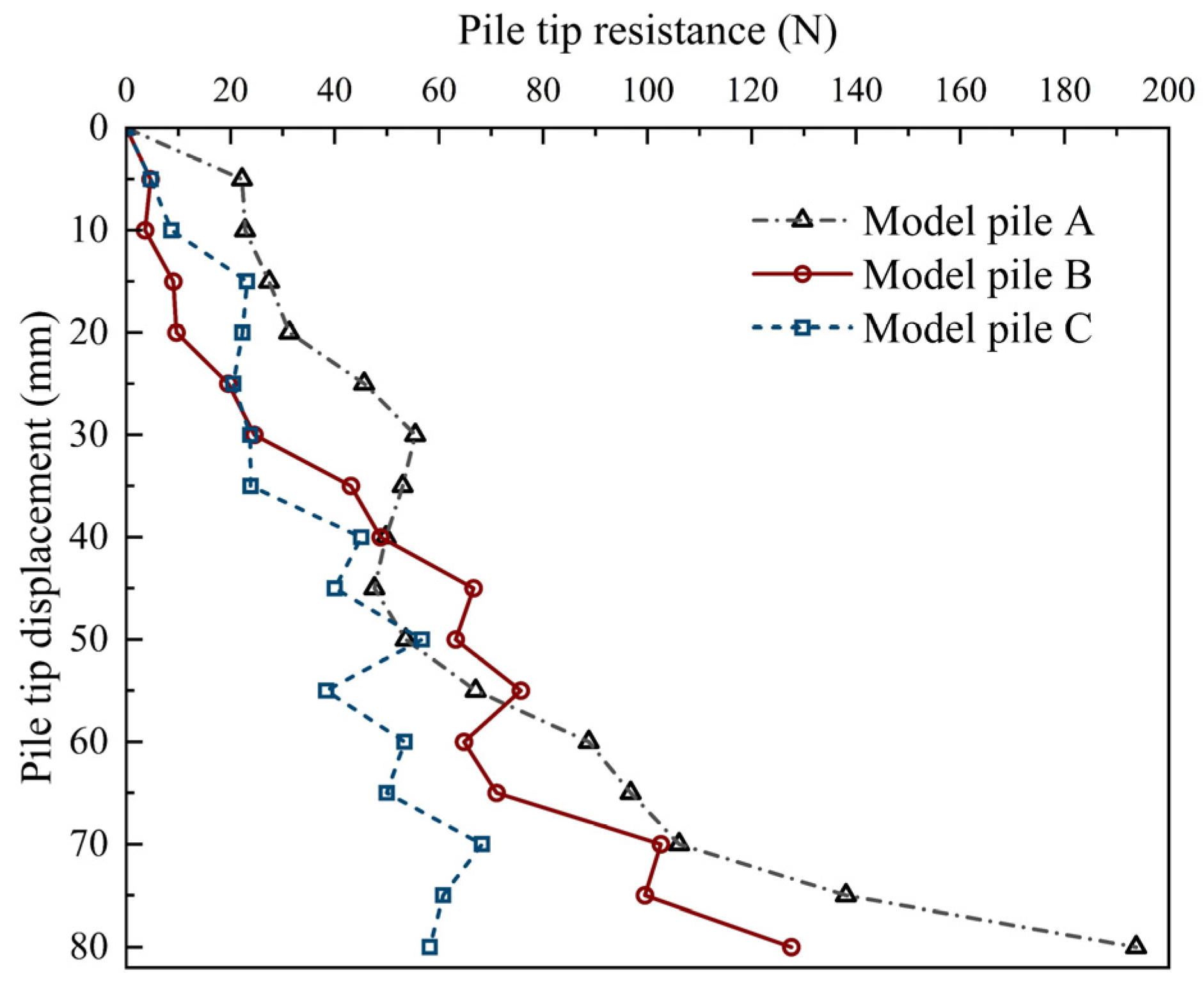
3.1. Pile Tip Resistance during Pile Driving

In the process of pile driving, the pile tip resistance and pile tip displacement are measured and recorded using the MTS system, and the results of different model piles are shown in Figure 3. It is readily seen that with the increase in pile depth, the pile tip resistance of different model piles continuously increases, but it also fluctuates obviously. The reason for this is that the calcareous sand particles break during the process of pile driving and dissipate energy, which makes the pile tip resistance decrease slightly; with the deepening of pile driving, the pile tip resistance increases, which induces a higher degree of particle breakage and the more obvious fluctuation in pile tip resistance. The pile tip resistance of different pile types is different. In general, the pile tip resistance of model pile A, which simulates the shape of a pipe pile, is the largest during pile driving, and the influence of particle breakage on it is the least significant, which also leads to the small fluctuation in pile tip resistance. The pile tip resistance of model pile B, which simulates the shape of a pointed square pile, is the second greatest. Model pile C, which simulates a semi-closed steel pipe pile, has the least pile tip resistance, experiencing the greatest influence of particle breakage and the biggest fluctuation in pile tip resistance. Even after a certain pile depth (>40 mm), the increase in the pile tip resistance is small and tends to be stable. These macroscopic mechanical changes can be explained by the particle breakage and the contact force variation between particles corresponding to the micro-evidence.

3.2. Particle Breakage during Pile Driving

In terms of the particle breakage, using fixed-point photogrammetry, the changes in the calcareous sand foundation with different model piles under different pile depths are obtained, as shown in Figure 4. Representative in clearly showing the particle variation during pile driving, the changes in the calcareous sand particles near model pile A and on the surface at different pile depths are extracted, as shown in Figure 5. It can be found that with the increase in pile depth, the calcareous sand particles at the bottom of the pile tip undergo a cyclic process from thinning to densification and from a large particle size to a small particle size. When the pile depth is small (0~20 mm), the calcareous sand particles under the pile tip are continuously compacted, and the bearing capacity increases. After reaching a certain stress limit (pile depth at 20–40 mm), the calcareous sand particles under the pile tip are broken, resulting in more fine particles and a sparse arrangement. The energy dissipation and foundation bearing capacity decrease, which provides micro-evidence supporting the slight decline in the pile tip resistance of model pile A when the pile depth is 30–45 mm. When the pile depth is around 40–50 mm, with the re-compaction, the calcareous sand at the bottom of the pile tip reaches a much denser state, and the final bearing capacity increases. The position of the calcareous sand particles at the bottom of the pile tip changed significantly with a pile depth at 50~80 mm, and the flat calcareous sand particles on both sides of the pile gradually filled the gap between the pile shaft and the wall of the model box, resulting in the particle breakage not being obvious.
Likewise, similar change rules can also be found in model pile B and model pile C, but the corresponding particle breakage and energy accumulation of the different model piles are different, resulting in differences in the value and change points of pile tip resistance.

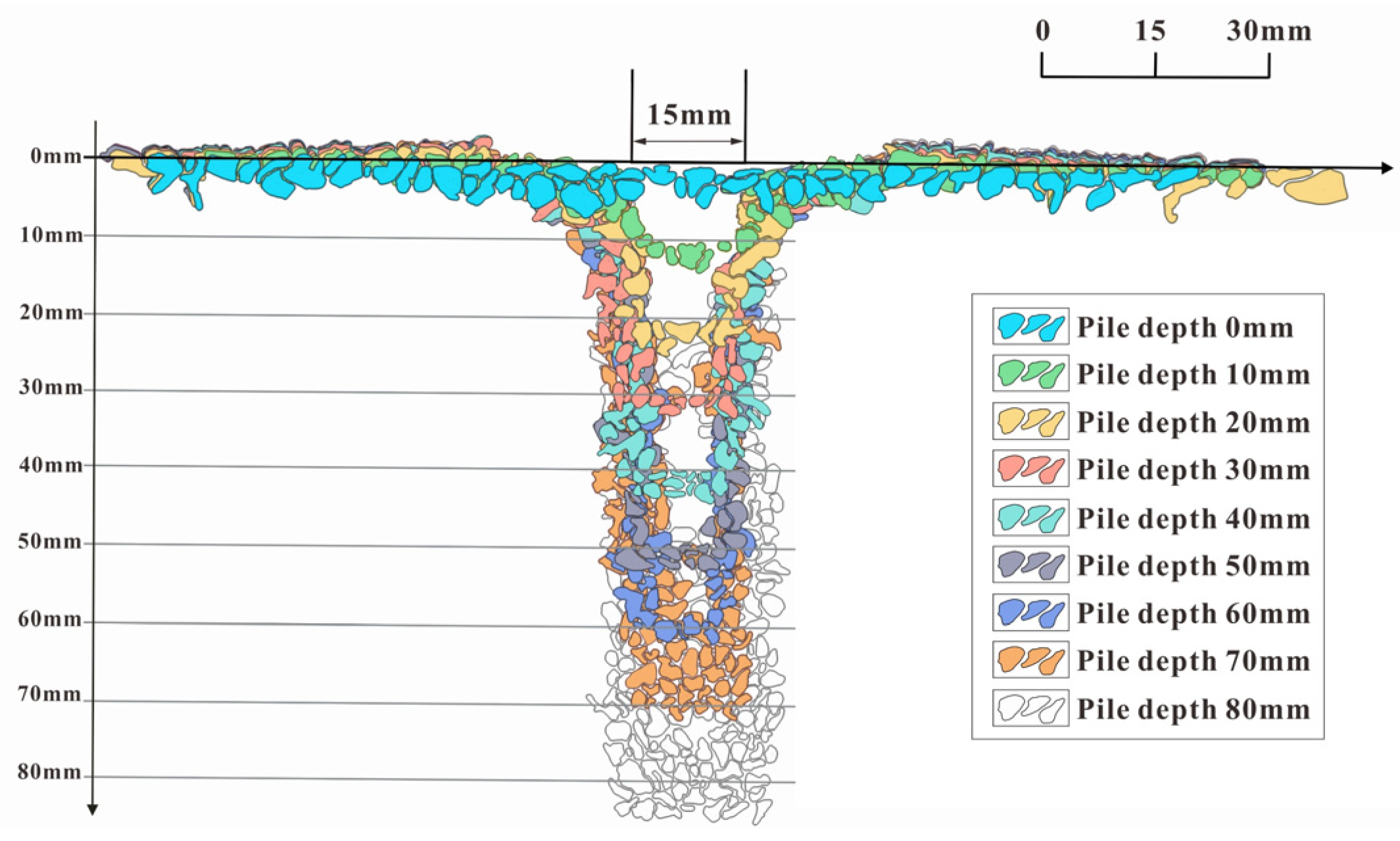
3.3. Deformation Characteristics during Pile Driving

Based on the image obtained using fixed-point photography in front of the model box, Figure 6 shows the surface deformation of the calcareous sand foundation obtained using tracing and extraction in the process of pile driving with different model piles. With the continuous driving of model pile A (Figure 6a), a funnel-shaped groove is gradually formed on the surface of the calcareous sand foundation within the range of one pile diameter from the pile shaft, while the calcareous sand outside the funnel-shaped groove produces a slight extrusion uplift. Until a distance of five times the pile diameter from the pile shaft, the driving of the model pile hardly caused deformation on the surface of the calcareous sand foundation. However, model pile B is different from model pile A (Figure 6b). When the pile depth is relatively small (0~40 mm), the surface of the calcareous sand foundation near the pile produces an extrusion uplift; meanwhile, when the pile depth is relatively large (50–80 mm), the uplifts close to both sides of the pile body gradually move outward, and a small funnel-shaped groove is formed within one of the pile diameter from the pile shaft, but the groove depth does not change significantly with the pile depth. The surface displacement of model pile C (Figure 6c) is also similar to that of model pile A, but the depth of the funnel-shaped groove is the smallest among the different model piles.
By comparing the changes in the surface deformation of the calcareous sand foundation with different model piles, it can be found that model pile C has the smallest induced vertical deformation and influence range on the surface of the calcareous sand foundation, followed by model pile B, while model pile A has the most obvious pile driving effect and the most significant effect on the deformation and destruction of the calcareous sand around the pile.

3.4. Internal Stress Evolution in Calcareous Sand Foundation during Pile Driving

3.4.1. Vertical Stress Distribution

In terms of the contact force between particles, the vertical stress distribution in the calcareous sand foundation at 10 mm below the pile tip at the maximum driving depth is measured using the tactile pressure sensor. The distributions of and changes in the vertical stress generated by different model piles in the calcareous sand foundation during the driving process are shown in Figure 7. It can be seen that during pile driving, the stress distribution in the calcareous sand foundation is not uniform, whereas the influence range of pile driving is limited, and, further, the stress concentration is mainly generated in the range of about double the pile diameter around the pile. When the pile depth reaches 60 mm, an obvious stress concentration zone is formed in the calcareous sand foundation under the center of the pile. The vertical stress distribution of model pile B and model pile C at different pile depths is more uniform than that of model pile A, and their stress concentration zone is relatively less obvious.

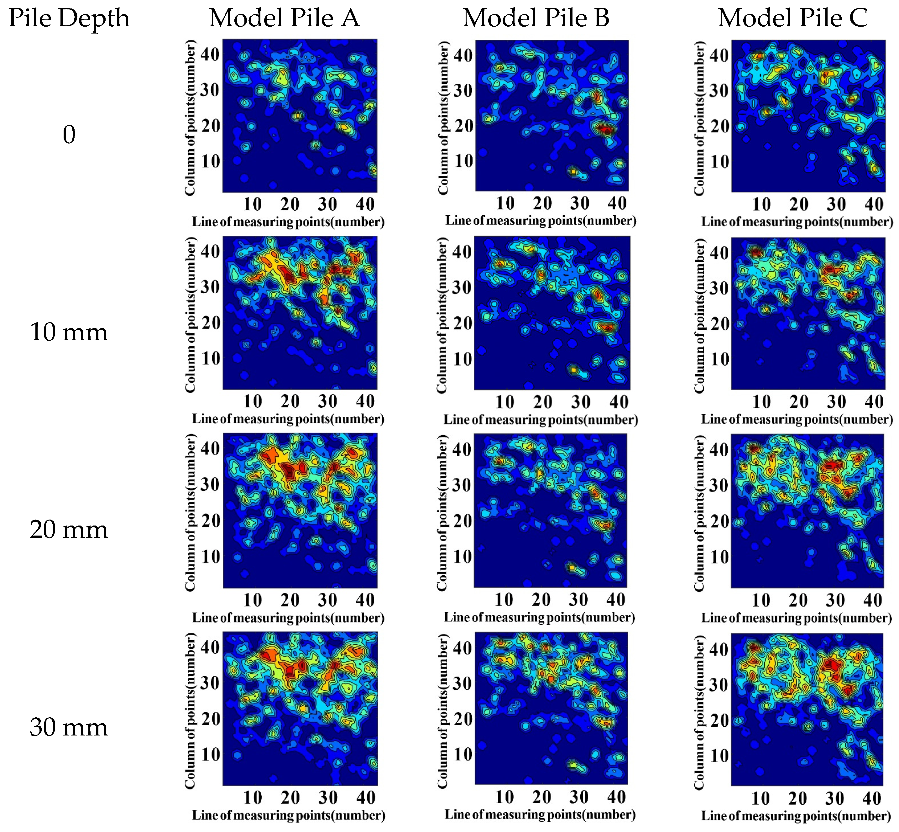
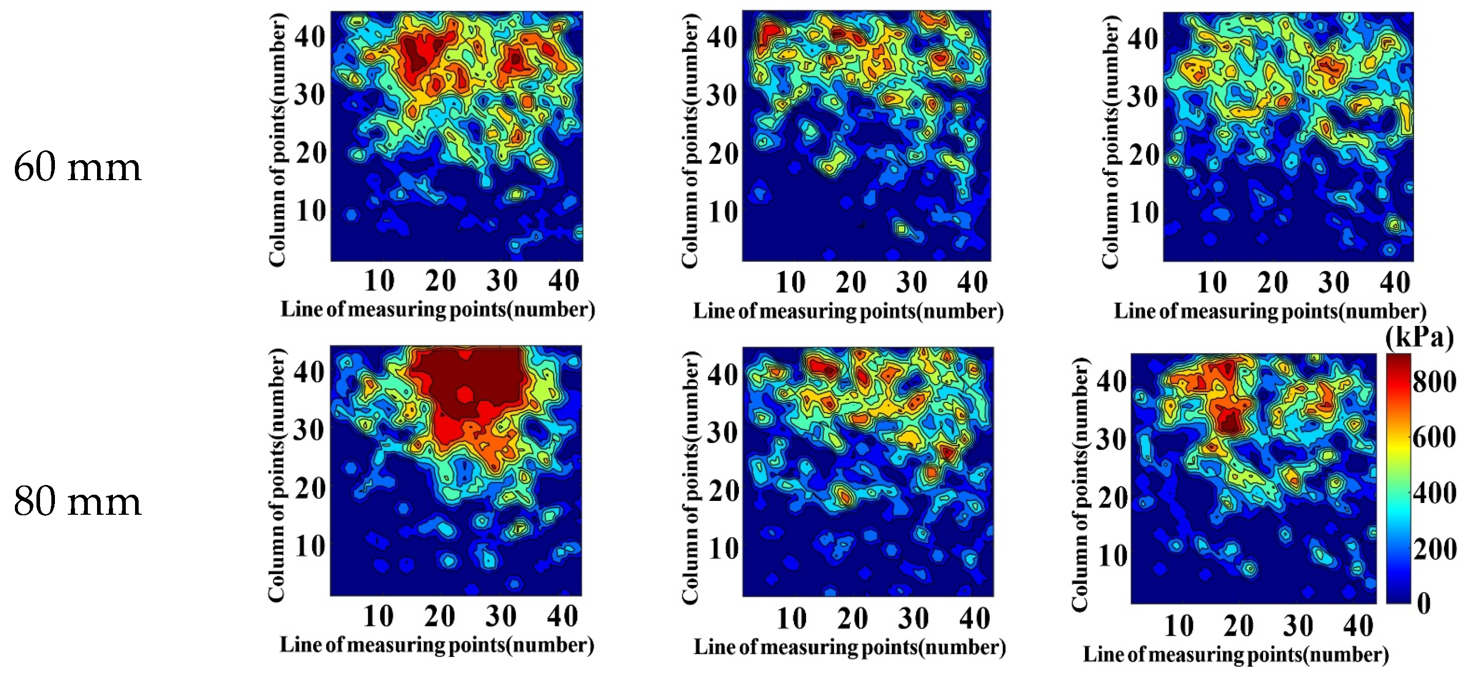
3.4.2. Radial Stress Distribution in a Calcareous Sand Foundation during Pile Driving

The radial stress distribution and the variation generated by different model piles in a calcareous sand foundation during pile driving are obtained. Among them, the original results of the radial stress distribution of model pile A measured using a tactile pressure are representatively shown in Table 1. It can be seen that with the increase in the pile depth, the radial stress around model pile A in the calcareous sand foundation first increases until it reaches a peak at a pile depth of 30 mm, and then decreases, which reflects the influence of the pile driving and the relative position in the foundation. As the pile depth increases, the pile tip gradually approaches, passes through and finally moves away from the position of the circumferential tactile pressure sensor. The radial stresses of model pile B and model pile C also have the same change trend during the process of pile driving in the calcareous sand foundation.

3.5. Deformation during Pile Setup

By comparing the surface deformation of the calcareous sand foundation with different model piles before and after the pile setup (Table 2), it can be seen that after 24 h, the uplift on the surface of the calcareous sand foundation basically is recovered and becomes flat, and the calcareous sand particles near the piles are consolidated under the self-weight. However, the range and degree of compaction for different model piles are different, which corresponds to the change in vertical and radial stress. Given the above, during the pile setup, the deformation of the foundation and the settlement of the piles themselves is small and negligible, but with the extension in time, the internal forces in the calcareous sand foundation is redistributed, and both the vertical and radial stresses in the foundation increase. In other words, when there is no obvious particle breakage in the calcareous sand foundation, the pile tip resistance and shaft resistance increase.

4. Discussion

The macro-behavior is highly related to the micro-information. The underlying mechanism of different pile type effects in the calcareous sand foundation can be explored according to the internal stress obtained using the tactile pressure sensors. The mean stress and coefficient of variation in stress are used to characterize the stress distribution, in which the coefficient of variation is the ratio of standard deviation to the mean value, ranging from 0 to 1. The smaller the coefficient of variation, the smaller the dispersion degree of the data and the more concentrated it is in a smaller range. And the data processing method of normalization is used: the data before the test (i.e., the pile depth is 0 mm) are taken as the initial value, then the normalized data are the ratio between the data and the initial value.

4.1. During Pile Driving

By comparing the vertical stress at the bottom of the pile tip in the calcareous sand foundation across different model piles (Figure 8), the results show that the vertical stress increases with the increase in the pile depth, among which model pile A has the largest increment, suggesting the highest potential vertical bearing capacity. Since the pile tip area of model pile B and model pile C is small, the interparticle stress can be easily highly concentrated, which induces more particle breakage and energy dissipation and, in turn, decreases the interparticle stress. This is why their corresponding vertical stress increases are relatively small, and the related bearing capacity provided by the pile tip is also limited. The vertical stress of model pile C tends to be constant at a certain depth with the largest relative particle breakage, which is consistent with the change in the pile tip resistance in Figure 3 and the conclusion reached by Gao et al. [46] using DEM numerical simulation. The coefficient of variation in vertical stress decreases with the increase in the pile depth, that is, the stress distribution tends to be uniform.
The changes in the normalized radial mean stress and coefficient of variation of different model piles with pile depth are shown in Figure 9. It can be found that with an increasing depth of pile driving, the coefficient of variation is slightly changed compared with that for vertical stress. It decreases first (indicating that the stress tends to be uniform) and then increases (indicating that the stress is more concentrated). Model pile C needs a larger pile depth to reach the maximum radial stress, reflecting a higher particle breakage degree, and it is difficult for model pile C to accumulate energy compared with other model piles, which is consistent with the above analysis. According to the increment in the mean radial stresses of different model piles, it is considered that model pile A has the largest influence range on the lateral force in the calcareous sand foundation, while model pile B has the smallest influence, which is due to the difference in the pile end shape.

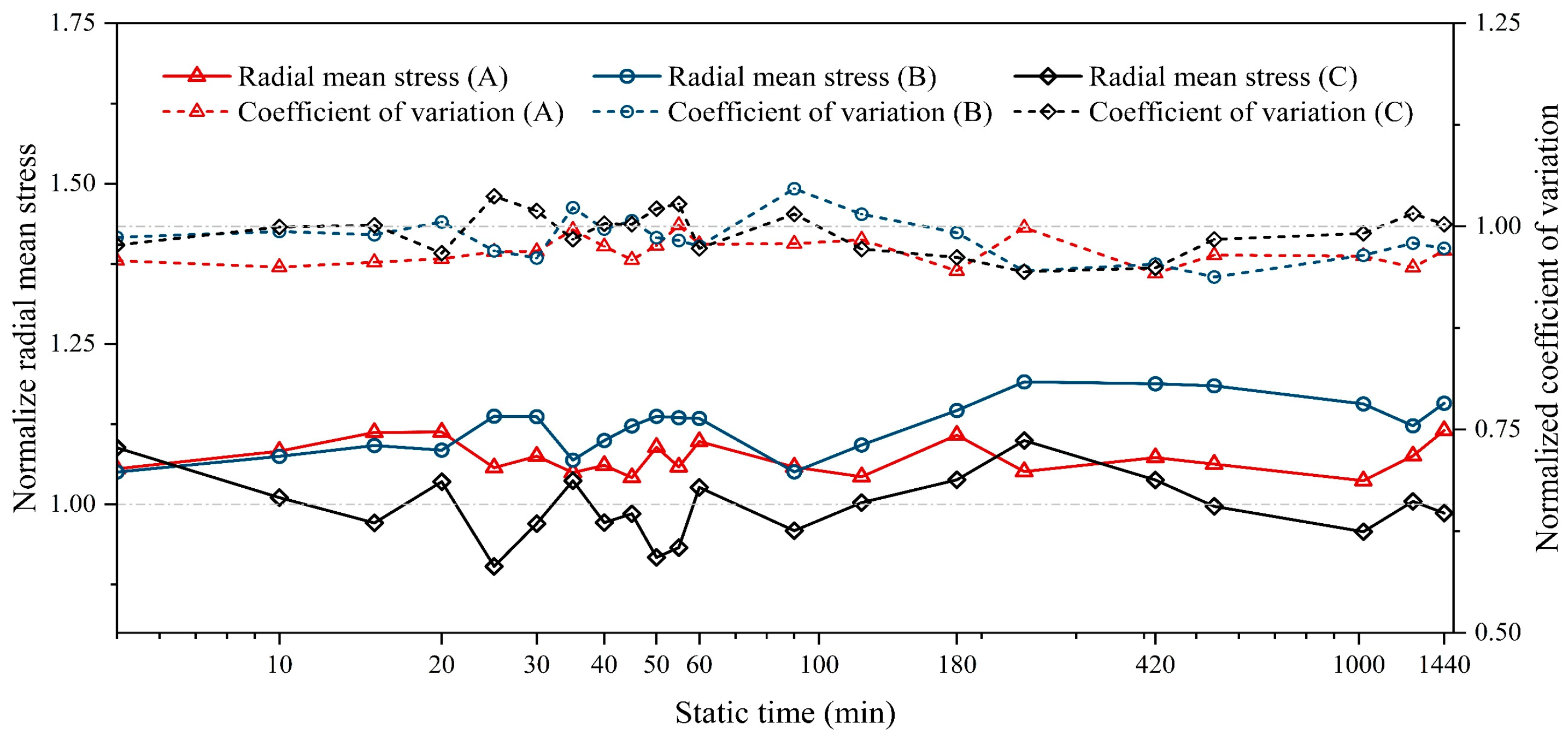
4.2. During Pile Setup

In the actual pile foundation, after pile driving is completed, the piles are left in place without external forces until monitoring is deemed satisfactory, or the next phase of construction commences. Consequently, compared to previous studies [43,45,51], this paper presents a more comprehensive analysis of the pile setup in a calcareous sand foundation, thereby revealing a deeper understanding of the underlying mechanism within real-world pile foundation engineering.
After the pile was driven to the target depth, the external force on the model pile was removed. That is, the buried depth of the model pile was kept at the designed pile depth of 80 mm for 24 h to develop the setup process, and the change in the stress distribution in the calcareous sand foundation was monitored. It is found that the global stress distribution changes a little with some local changes. The clear variations in the normalized vertical mean stress and coefficient of variation for different model piles along with increasing time are shown in Figure 10. It can be seen that the coefficient of variation in vertical stress decreases and the vertical mean stress increases after 24 h only under gravity. In other words, stress redistribution occurs in the calcareous sand foundation over time, and it tends to be more uniform, which induces a slight increase in its bearing capacity.
The radial stress distribution of different model piles before and after the pile setup shows little global change but some local changes. The much clearer changes in the normalized radial mean stress and the coefficient of variation in radial stress for different model piles over time are shown in Figure 11. It is found that the radial mean stress in the calcareous sand foundation with model pile A and model pile B increases with time, and the coefficient of variation decreases, although the decrease in the coefficient of variation is not as large as that of the vertical stress. The decreasing coefficient of variation indicates a more uniform stress distribution, which can give a more stable internal structure. But for model pile C, the corresponding radial stress has no obvious change after a certain time. Based on the changes in vertical and radial stress, it is concluded that model pile B has the largest increase in total stress and the most obvious increase in potential bearing capacity, followed by model pile A, and model pile C has the smallest increase.

5. Conclusions

In this study, three different model piles were designed based on three common pile shapes, which were pipe piles, pointed square piles and semi-closed steel pipe piles. Using the model tests of pile driving and pile setup in a calcareous sand foundation, the pile driving and time effect and mechanical properties in calcareous sand foundations for different pile types were explored, and the main conclusions are as follows.
(1) In the process of pile driving, with an increase in pile depth, the pile tip resistance of different pile models increases in general, while there are fluctuations caused by the particle breakage of the calcareous sand and energy dissipation. As the pile is driven deeper, the fluctuation in the pile tip resistance becomes more pronounced. The pile tip resistance for model pile A simulating a pipe pile is the highest, followed by model pile B simulating a pointed square pile and model pile C simulating a semi-closed steel pipe pile has the least. It is considered that, at the completion of pile driving, the potential bearing capacity of model pile A is the highest, followed by model pile B, and model pile C has the smallest potential bearing capacity.
(2) The results on the interparticle stress distributions in the calcareous sand foundation during pile driving are well in agreement with the global pile tip resistance behavior. The vertical stress concentration is mainly generated in the range of double the pile diameter around the pile in calcareous sand foundations. The radial stress is increased by the pile passing through. With an increasing pile depth, the stress distribution tends to be uniform, which is characterized by the reducing coefficient of variation in interparticle stresses; the mean vertical stress for model pile A has the largest increase, followed by model pile B and model pile C, which can explain the change in pile tip resistance.
(3) During pile driving, the calcareous sand foundation surface gradually forms a funnel-shaped groove, and a slight extrusion uplift occurs outside the groove. Model pile C has the smallest deformation and impact range on the surface of the calcareous sand foundation, followed by model pile B. Model pile A has the most obvious pile driving effect with the most significant deformation and influence range on the calcareous sand foundation around the pile.
(4) With a certain duration of pile setup, the vertical and radial stresses in the calcareous sand foundation with different pile models also tend to be redistributed and become uniform, and the average vertical and radial stresses increase. This indicates that the total potential bearing capacity increases after a certain time. The increased magnitude in reverse order from large to small spans model pile B, A, then C. The uplift deformation of the ground surface is also recovered.
(5) Considering the potential bearing capacity of different model piles, the influence range of pile driving, foundation deformation and pile setup, model pile B has a good bearing capacity potential and a small deformation and damage effect on calcareous sand foundations. It is suggested to use a pointed square pile corresponding to model pile B in pile foundation engineering for calcareous sand foundations. Large-scale prototype tests are also recommended for further identification in the future.

Author Contributions

Conceptualization, Y.G. and Z.G.; methodology, Y.G.; validation, Y.G., Z.G. and Q.Y.; formal analysis, Y.G. and Z.G.; investigation, Y.G. and Q.Y.; resources, Y.G.; data curation, Y.G.; writing—original draft preparation, Z.G.; writing—review and editing, Y.G. and Q.Y.; visualization, Z.G.; supervision, Y.G.; project administration, Y.G.; funding acquisition, Y.G. All authors have read and agreed to the published version of the manuscript.

Funding

This research was funded by National Natural Science Foundation of China, grant number 42072295, Guangdong Project, grant number 2017ZT07Z066, National Key R&D Program of China, grant number 2022YFC3005203, and Guangdong Provincial Key Laboratory of New Construction Technology for Urban Rail Transit Engineering (2017B030302009).

Institutional Review Board Statement

Not applicable.

Informed Consent Statement

Not applicable.

Data Availability Statement

The raw data supporting the conclusions of this article will be made available by the authors on request.

Conflicts of Interest

Author Quan Yuan was employed by the company Guangzhou Metro Design and Research Institute Co., Ltd. The remaining authors declare that the research was conducted in the absence of any commercial or financial relationships that could be construed as a potential conflict of interest.

References

  1. Gao, Y.; Shi, T.; Yuan, Q.; Sun, K. The creep characteristics and related evolution of particle morphology for calcareous sand. Powder Technol. 2024, 431, 119077. [Google Scholar] [CrossRef]
  2. Wang, X.; Jiao, Y.; Wang, R.; Hu, M.; Meng, Q.; Tan, F. Engineering characteristics of the calcareous sand in Nansha Islands, South China Sea. Eng. Geol. 2011, 120, 40–47. [Google Scholar] [CrossRef]
  3. Ye, J.; Haiyilati, Y.; Cao, M.; Zuo, D.; Chai, X. Creep characteristics of calcareous coral sand in the South China Sea. Acta Geotech. 2022, 17, 5133–5155. [Google Scholar] [CrossRef]
  4. Murff, J.D. Pile Capacity in Calcareous Sands: State if the Art. J. Geotech. Eng. 1987, 113, 490–507. [Google Scholar] [CrossRef]
  5. Fan, Z.; Hu, C.; Zhu, Q.; Jia, Y.; Zuo, D.; Duan, Z. Three-dimensional pore characteristics and permeability properties of calcareous sand with different particle sizes. Bull. Eng. Geol. Environ. 2021, 80, 2659–2670. [Google Scholar] [CrossRef]
  6. Zhu, C.; Wang, X.; Wang, R.; Chen, H.; Meng, Q. Experimental microscopic study of inner pores of calcareous sand. Mater. Res. Innov. 2014, 18, S2-207–S2-214. [Google Scholar] [CrossRef]
  7. Shen, Y.; Zhu, Y.; Liu, H.; Li, A.; Ge, H. Macro-meso effects of gradation and particle morphology on the compressibility characteristics of calcareous sand. Bull. Eng. Geol. Environ. 2018, 77, 1047–1055. [Google Scholar] [CrossRef]
  8. Touiti, L.; Kim, T.; Jung, Y.H. Analysis of calcareous sand particle shape using fourier descriptor analysis. Int. J. Geo-Eng. 2020, 11, 15. [Google Scholar] [CrossRef]
  9. Kuang, D.; Long, Z.; Guo, R.; Zhao, T.; Wu, K. Experimental and numerical study on the fragmentation mechanism of a single calcareous sand particle under normal compression. Bull. Eng. Geol. Environ. 2021, 80, 2875–2888. [Google Scholar] [CrossRef]
  10. Lyu, H.; Gu, J.; Zhou, J.; Li, B. Mechanical behavior and particle breakage of calcareous sand in triaxial test. Mar. Geophys. Res. 2023, 44, 18. [Google Scholar] [CrossRef]
  11. Ma, C.; Qu, R.; Zhu, C.; Liu, H.; Wang, T. Microscopic study of the impact of particle morphology on the compressibility of calcareous sands. Powder Technol. 2024, 433, 119192. [Google Scholar] [CrossRef]
  12. Shen, Y.; Rui, X.; Ma, Y.; Shen, J.; Xu, J. Anisotropic behaviors of calcareous sand dependent on loading direction and initial shear stress. Appl. Ocean Res. 2023, 141, 103775. [Google Scholar] [CrossRef]
  13. Jin, H.; Zhou, L.; Guo, L.; Tong, J. Comparative Study on Liquefaction Behavior of Calcareous Sand and Siliceous Sand Under Simple Shear Loading. J. Earthq. Eng. 2023, 27, 3471–3489. [Google Scholar] [CrossRef]
  14. Kurniawan, R.; Nghia-Nguyen, T.; Kikumoto, M. Mechanical behavior of porous crushable soils: Effect of intragranular porosity. IOP Conf. Ser. Earth Environ. Sci. 2023, 1249, 012024. [Google Scholar] [CrossRef]
  15. Luo, M.; Zhang, J.; Liu, X.; Wu, C. Effect of Particle Breakage and Interlocking on Strength and Dilatancy Characteristics of Calcareous Sands. KSCE J. Civ. Eng. 2023, 27, 3270–3284. [Google Scholar] [CrossRef]
  16. Xiang, C.; Xu, D.; Shen, J.; Wei, H.; Wang, R. Effect of particle size and particle distribution pattern on dynamic behavior of cemented calcareous sand. Mar. Georesour. Geotechnol. 2023, 41, 412–424. [Google Scholar] [CrossRef]
  17. Gilchrist, J.M. Load Tests on Tubular Piles in Coralline Strata. J. Geotech. Eng. 1985, 111, 641–655. [Google Scholar] [CrossRef]
  18. Neely, K.L.; Lewis, C.L.; Macaulay, K.A. Disparities in Spawning Times between in situ and ex situ Pillar Corals. Front. Mar. Sci. 2020, 7, 643. [Google Scholar] [CrossRef]
  19. Zhu, C.Q.; Liu, H.F.; Wang, X.; Meng, Q.S.; Wang, R. Engineering geotechnical investigation for coral reef site of the cross-sea bridge between Malé and Airport Island. Ocean Eng. 2017, 146, 298–310. [Google Scholar] [CrossRef]
  20. Wang, C.; Ding, X. Effect of Vertical Load on Lateral Response of Single Piles in Coral Sand. In Proceedings of the 2022 International Conference on Green Building, Civil Engineering and Smart City, Guilin, China, 8–10 April 2022. [Google Scholar] [CrossRef]
  21. Lehane, B.M.; Schneider, J.A.; Lim, J.K.; Mortara, G. Shaft Friction from Instrumented Displacement Piles in an Uncemented Calcareous Sand. J. Geotech. Geoenviron. Eng. 2012, 138, 1357–1368. [Google Scholar] [CrossRef]
  22. Hu, H.; Luo, L.; Lei, G.; Guo, J.; He, S.; Hu, X.; Guo, P.; Gong, X. The Transverse Bearing Characteristics of the Pile Foundation in a Calcareous Sand Area. Materials 2022, 15, 6176. [Google Scholar] [CrossRef] [PubMed]
  23. Qin, Y.; Xu, D.; Fan, X. Effect of pile inclination on the lateral deformation behaviour of pipe piles in calcareous sand. Mar. Georesour. Geotechnol. 2022, 40, 589–599. [Google Scholar] [CrossRef]
  24. Spagnoli, G.; Scheller, P. Doherty, In situ and laboratory tests on a novel offshore mixed-in-place pile for oil and gas platforms. J. Pet. Sci. Eng. 2016, 145, 502–509. [Google Scholar] [CrossRef]
  25. Ouyang, H.; Dai, G.; Qin, W.; Zhang, C.; Gong, W. Dynamic behaviors of calcareous sand under repeated one-dimensional impacts. Soil Dyn. Earthq. Eng. 2021, 150, 106891. [Google Scholar] [CrossRef]
  26. Salem, T.N.; Elkhawas, N.M.; Elnady, A.M. Behavior of Offshore Pile in Calcareous Sand—Case Study. J. Mar. Sci. Eng. 2021, 9, 839. [Google Scholar] [CrossRef]
  27. Liu, H.; Wang, C.; Ding, X.; Zhang, Y. Comparative numerical analysis of the response of laterally loaded pile in coral and silica sands. Acta Geotech. 2023, 18, 4767–4787. [Google Scholar] [CrossRef]
  28. Ding, X.; Deng, X.; Ou, Q.; Deng, W. Experimental study on the behavior of single pile foundation under vertical cyclic load in coral sand. Ocean Eng. 2023, 280, 114672. [Google Scholar] [CrossRef]
  29. Xu, D.; Huang, F.; Rui, R. Investigation of Single Pipe Pile Behavior Under Combined Vertical and Lateral Loadings in Standard and Coral Sands. Int. J. Geosynth. Ground Eng. 2020, 6, 20. [Google Scholar] [CrossRef]
  30. Wei, H.; Xin, L.; Li, W.; Li, X.; Yang, M.; Chen, Y. Oblique tensile tests on model anchor piles in calcareous sand deposits. Ocean Eng. 2024, 291, 116285. [Google Scholar] [CrossRef]
  31. Wu, Q.; Ding, X.; Zhang, Y. Dynamic interaction of coral sand-pile-superstructure during earthquakes: 3D numerical simulations. Mar. Georesour. Geotechnol. 2023, 41, 774–790. [Google Scholar] [CrossRef]
  32. Wu, Q.; Ding, X.; Chen, Z.; Zhang, Y. Shaking Table Tests on Seismic Responses of Pile-soil-superstructure in Coral Sand. J. Earthq. Eng. 2020, 26, 3461–3487. [Google Scholar] [CrossRef]
  33. McDowell, G.R.; Bolton, M.D. Effect of Particle Size Distribution on Pile Tip Resistance in Calcareous Sand in the Geotechnical Centrifuge. Granul. Matter 2000, 2, 179–187. [Google Scholar] [CrossRef]
  34. Houlsby, G.T.; Nutt, N.R.F.; Sweeney, M. End Bearing Capacity of Piles in Carbonate Soils. In Proceedings of the 13th International Conference on Soil Mechanics and Foundation Engineering, New Delhi, India, 5–10 January 1994. [Google Scholar]
  35. Wang, Q.; Xiao, Z.; Zhao, X.; Feng, D. The Effects and Vertical Bearing Capacity of Two Jacked Model Piles in Sand. Sustainability 2022, 14, 14493. [Google Scholar] [CrossRef]
  36. Huynh, T.Q.; Nguyen, T.T.; Nguyen, H. Base resistance of super-large and long piles in soft soil: Performance of artificial neural network model and field implications. Acta Geotech. 2023, 18, 2755–2775. [Google Scholar] [CrossRef]
  37. Al-Douri, R.H.; Poulos, H.G. Predicted and Observed Cyclic Performance of Piles in Calcareous Sand. J. Geotech. Eng. 1995, 121, 1–16. [Google Scholar] [CrossRef]
  38. Malakshah, R.R.; Moradi, M.; Ghalandarzadeh, A. Centrifuge Modelling of Monopiles in Calcareous Sand Subjected to Cyclic Lateral Loading. Int. J. Civ. Eng. 2022, 20, 195–206. [Google Scholar] [CrossRef]
  39. Wang, S.; Lei, X.; Meng, Q.; Xu, J.; Wang, M.; Guo, W. Model Tests of Single Pile Vertical Cyclic Loading in Calcareous Sand. Mar. Georesour. Geotechnol. 2021, 39, 670–681. [Google Scholar] [CrossRef]
  40. Jiang, H.; Wang, R.; Lv, Y.; Meng, Q. Test Study of Model Pile in Calcareous Sands. Rock Soil Mech. 2010, 31, 780–784. (In Chinese) [Google Scholar] [CrossRef]
  41. Jiang, H.; Wang, R.; Lv, Y.; Meng, Q. Model Tests of Pile Groups in Calcareous Sands. Chin. J. Rock Mech. Eng. 2010, 29, 3023–3028. (In Chinese) [Google Scholar]
  42. Yang, C.; Jiang, H. The Comparative Study of Single Pile Bearing Characteristics in Calcareous Sands Foundation and Quartz Sands Foundation Based on Model Experiment. IOP Conf. Ser. Earth Environ. Sci. 2020, 455, 012086. [Google Scholar] [CrossRef]
  43. Wan, Z.; Liu, H.; Zhou, F.; Dai, G. Axial Bearing Mechanism of Post-Grouted Piles in Calcareous Sand. Appl. Sci. 2022, 12, 2731. [Google Scholar] [CrossRef]
  44. Wan, Z.; Dai, G.; Gong, W. Study on the response of postside-grouted piles subjected to lateral loading in calcareous sand. Acta Geotech. 2022, 17, 3099–3115. [Google Scholar] [CrossRef]
  45. Peng, Y.; Liu, J.; Ding, X.; Fang, H.; Jiang, C. Performance of X-Section Concrete Pile Group in Coral Sand Under Vertical Loading. China Ocean Eng. 2020, 34, 621–630. [Google Scholar] [CrossRef]
  46. Gao, Y.; Yu, J.; Wang, Y.; Li, W.; Shi, T. Breakage Effect of Calcareous Sand on Pile Tip Resistance and the Surrounding Soil Stress. Energy Rep. 2022, 8, 183–190. [Google Scholar] [CrossRef]
  47. Peng, Y.; Ding, X.; Yin, Z.; Wang, P. Micromechanical analysis of the particle corner breakage effect on pile penetration resistance and formation of breakage zones in coral sand. Ocean Eng. 2022, 259, 111859. [Google Scholar] [CrossRef]
  48. Jiang, H. Research on Bearing Behavior of Pile Foundation in Calcareous Sands. Ph.D. Dissertation, The Chinese Academy of Sciences (Institute of Rock and Soil Mechanics), Wuhan, China, 2009. (In Chinese). [Google Scholar]
  49. Ovensen, N.K. The Use of Physical Models in Design: The Scaling Law Relationships. In Proceedings of the 7th European Conference on Soil Mechanics and Foundation Engineering, Brighton, UK, 10–13 September 1979. [Google Scholar]
  50. Dyson, G.J.; Randolph, M.F. Monotonic Lateral Loading of Piles in Calcareous Sand. J. Geotech. Geoenviron. Eng. 2001, 127, 346–352. [Google Scholar] [CrossRef]
  51. Peng, Y.; Liu, H.; Li, C.; Ding, X.; Deng, X.; Wang, C. The detailed particle breakage around the pile in coral sand. Acta Geotech. 2021, 16, 1971–1981. [Google Scholar] [CrossRef]
Figure 1. Schematic diagram of the model piles with different shapes and sizes.
Jmse 12 00133 g001
Figure 2. Measurement system of tactile pressure sensors and arrangement: (a) measurement system of tactile pressure sensors; (b) the arrangement of tactile pressure sensors.
Jmse 12 00133 g002
Figure 3. Pile tip resistance–displacement curves of different pile models during pile driving.
Jmse 12 00133 g003
Figure 4. Changes in calcareous sand foundation during pile driving process for different types of piles. The soil around the pile is also enlarged as show in the marked box.
Jmse 12 00133 g004
Figure 5. Changes in calcareous sand particles of model pile A under different pile depths.
Jmse 12 00133 g005
Figure 6. Surface deformation of calcareous sand foundation in the process of pile driving: (a) model pile A; (b) model pile B; (c) model pile C.
Jmse 12 00133 g006
Figure 7. Vertical stress distributions of different types of model piles at different pile depths.
Jmse 12 00133 g007aJmse 12 00133 g007b
Figure 8. Variations in vertical stresses for different model piles during pile driving process.
Jmse 12 00133 g008
Figure 9. Changes in radial stresses for different model piles during pile driving process.
Jmse 12 00133 g009
Figure 10. The variations in vertical mean stress and coefficient of variation over time.
Jmse 12 00133 g010
Figure 11. The variations in radial mean stress and coefficient of variation with time.
Jmse 12 00133 g011
Table 1. Radial stress distribution of model pile A at different pile depths.
Pile Depth 0 mmPile Depth 30 mmPile Depth 80 mmStress
(kPa)
Two-dimensional
stress
contour
map
Jmse 12 00133 i001Jmse 12 00133 i002Jmse 12 00133 i003Jmse 12 00133 i004
Three-dimensional
stress
distribution
cloud
image
Jmse 12 00133 i005Jmse 12 00133 i006Jmse 12 00133 i007Jmse 12 00133 i008
Table 2. Changes in calcareous sand foundation for different model piles under different conditions. The soil around the pile is also enlarged as show in the marked box.
Model PileAfter Pile DrivingBefore Pile SetupAfter Pile Setup
Model plie AJmse 12 00133 i009Jmse 12 00133 i010Jmse 12 00133 i011
Model plie BJmse 12 00133 i012Jmse 12 00133 i013Jmse 12 00133 i014
Model plie CJmse 12 00133 i015Jmse 12 00133 i016Jmse 12 00133 i017
Disclaimer/Publisher’s Note: The statements, opinions and data contained in all publications are solely those of the individual author(s) and contributor(s) and not of MDPI and/or the editor(s). MDPI and/or the editor(s) disclaim responsibility for any injury to people or property resulting from any ideas, methods, instructions or products referred to in the content.

