Article

SPACNet: A Simulation Platform of an Acoustic Cognitive Network

1
College of Ocean and Earth Sciences, Xiamen University, Xiamen 361005, China
2
National and Local Joint Engineering Research Center for Navigation and Location Service Technology, Xiamen University, Xiamen 361005, China
3
Third Institute of Oceanography, Ministry of Natural Resources, Xiamen 361005, China
4
State Key Laboratory of Marine Environmental Science, Xiamen University, Xiamen 361005, China
*
Author to whom correspondence should be addressed.
J. Mar. Sci. Eng. 2023, 11(9), 1827; https://doi.org/10.3390/jmse11091827
Submission received: 18 July 2023 / Revised: 11 September 2023 / Accepted: 14 September 2023 / Published: 19 September 2023
(This article belongs to the Special Issue Underwater Acoustic Communication and Network)

Abstract

:
Originating from the concept of cognitive networks (CNs), which are becoming popular in wireless terrestrial communication scenarios, underwater acoustic cognitive networks (UACNs) are drawing more and more attention in the field of the Internet of Underwater Things (IoUT). However, as the implementation of cognitive mechanisms in underwater acoustic networks is different from that of wireless scenarios, it is impossible or difficult for traditional simulation platforms to carry out simulations of UACNs. There is a lack of specialized simulation tools in terms of UACNs. To enable the quantitative evaluation of the effectiveness and performance enhancement of a UACNs in an adverse underwater environment, a simulation platform of acoustic cognitive networks (SPACNet) was designed and investigated in this article. First, based on a state machine-based protocol programming framework, the SPACNet is capable of supporting the implementation of different state-transform types associated with cognitive networking protocols. Moreover, to facilitate the realization of cognitive function at comprehensive levels of signal, information, and link, an underwater acoustic channel model with an environmental parameter input is integrated in SPACNet to generate underwater environment-driven multiple-aspect behaviors. Moreover, a simplified collision model consisting of an environment factor, channel response, and node location is used to reduce the complexity of the simulation of UACNs signal reception. A simulation was carried out to verify the effectiveness of SPACNet in evaluating the cognitive capabilities of UACNs. Finally, a field UACNs experiment was performed to validate the general consistency between the conclusion obtained with the SPACNet-based simulation and that from the field test.

1. Introduction

The technology of underwater acoustic networks (UAN) has drawn substantial attention due to its significant potential in extensive civil and military fields, e.g., marine environment monitoring [1], marine resource exploration [2], marine disaster warning [3], underwater information acquisition and transmission [4], autonomous underwater vehicle-assisted navigation [5], communication between scuba divers [6], military applications [7], etc. Evolved from the concept of cognitive radio, the cognitive network (CN) technique has characteristics that optimize a network via environmental sensing, adaptive adjustment, intelligent decision-making, and reconfiguration.
In [8], the potential for partial data offloading to mobile edge computing (MEC) servers was investigated under the perspective of users’ cognitive IoT devices presenting loss-averse and gain-seeking behavior. Ref. [9] examined a disaster response cognitive relay network aided by an unmanned aerial vehicle (UAV), which contains a number of uplink cellular users as primary users, active device-to-device (D2D) users as secondary users, and idle D2D users that act as a virtual multiple-input multiple-output (MIMO) node. In [10], a UAVs-assisted two-hop cognitive radio network (CRN) was proposed, where multiple UAVs are employed to act as air access points and relay nodes.
Ref. [11] reviews the research of covert communications in cooperative cognitive radio networks via three intelligent covert transmission approaches, namely, intelligent parasitic covert transmission, intelligent jammer-aided covert transmission, and intelligent reflecting surface-assisted covert transmission.
Based on the point-to-point linkage provided by underwater acoustic modems, it is possible to construct a large-scale UAN consisting of a substantial number of nodes under the framework of the Internet of Underwater Things (IoUT) [12]. However, the performance of IoUT suffers from adverse underwater environments and random temporal–spatial–spectral uncertainties. By incorporating CNs with UANs, underwater acoustic cognitive networks (UACNs) offer a promising solution for the research and practical implementation of IoUT.
However, while cognitive networks have achieved significant progress in academic research, the R&D of the standard network model, and practical commercial applications based on established wireless channel sensing and cognitive optimization strategies [1,2,3,4,5,6,7,8], the specific implementation of CNs in the underwater acoustic channel still encounter many difficulties due to the highly diverse channel patterns, underwater acoustic (UWA) communication modes, and network protocols.
Moreover, considering the vast cost and resource associated with the underwater hardware, the supporting facilities, and the vessels required by underwater acoustic network field tests, simulation platforms are recognized as a low-cost and effective way for the comprehensive evaluation of UACNs schemes.
In [13], a receiver-initiated spectrum management system for underwater cognitive acoustic networks (UACNs) is proposed with the purpose of improving the performance of UACNs through a collaboration of a physical layer and a medium access control (MAC) layer. Ref. [14] proposed a cognitive acoustic transmission scheme by employing a probabilistic method to capture the stochastic characteristics of dolphins’ communications, and mathematically describing the dolphin-aware constraint to maximize the end-to-end throughput. Both studies in [13,14] adopted the simulation for the verification and performance evaluation of the proposed UACNs schemes.
Thus far, the simulation platform for UANs is still in its initial stage and is mainly based on the mature terrestrial simulation platforms, e.g., NS2, NS3, and OPNET. NS2 [15] is an object-oriented network simulation tool, i.e., essentially a discrete event-driven simulator, in which the running state of the entire network can be simulated. NS2 implements a hierarchical design for network simulations, including a compilation layer and an interpretation layer, responsible for processing data packets and configuring and establishing the simulation environment, respectively. Although the name NS3 [16] is similar to NS2 and it is driven by a discrete time mechanism, NS3 is not an extension of NS2 and does not support the NS2 application programming interface (API). Due to the advantage of abstracting common network devices and encapsulating them into corresponding classes, NS2 has been gradually replaced by NS3 in recent years. OPNET [17] is a commercial simulation platform used for network design, planning, and network protocol analysis and development. OPNET has a user-friendly interface, adopts layered modeling and discrete event-driven simulation mechanisms, and has a relatively complete model library.
To improve the quality of the overall architecture, the Aqua-Sim for NS2 and Aqua-Sim for NS3 were designed in [18,19], respectively, and various models were constructed, including the energy module of underwater communication aircraft, signal-to-interference-plus-noise ratio detection, a propagation model of underwater communication channels, underwater noise, etc. [20,21]. To facilitate the acquisition of real underwater acoustic channel simulation experiments, DESERT and SUNSET were designed in [22,23,24], respectively. DESERT and SUNSET not only improve the experimental accuracy but also have the convenience of software simulation protocol superposition and have successfully conducted multiple on-site tests [25,26,27]. In [28], a multithreaded NS3-based underwater acoustic network simulation architecture was designed for the parallel processing of multiple nodes and data packets. The simulation operates in a mode that combines real underwater environments, hardware nodes, and virtual protocol stacks. It can be directly ported to hardware platforms for experiments and verified using an underwater acoustic modem developed by the Chinese Academy of Sciences. In addition, some representative simulation and experimental platforms were introduced in [29], which are divided into three types: laboratory-level simulation platforms, short-term experimental verification platforms, and long-term on-site testing experimental platforms.
However, due to the significant differences between the implementation of underwater cognitive mechanisms and wireless scenarios, the physical layer communication modules and channel models of traditional network simulation platforms, such as OPNET, NS2, and NS3, are not suitable for UACNs. For example, when conducting UAN simulation in OPNET, special modifications and configurations need to be made to the wireless communication channel to simulate the underwater acoustic channel [30]. However, this method cannot provide the external environment information and node internal information required for a cognitive network, making it difficult to support UACNs. To better implement a UAN simulation, secondary development versions based on NS2 and NS3, such as Aqua-Sim for NS2 [18], Aqua-Sim for NS3 [19], DESERT [22,23], and SUNSET [24], have added specialized modules for the characteristics of UANs, especially in underwater acoustic environments. However, the cognitive process of nodes in an external environment cannot be well simulated, and using it for cognitive network protocol simulations cannot support research on different hardwares [31,32]. In addition, the configuration process of network simulation is cumbersome and inflexible. For example, the conversion of the DESERT header fields and the size assigned to each field are hard-coded and cannot be changed quickly by users. Any changes require recompiling the implemented code and updating the library. Compared to the DESERT, the SUNSET has a higher scheduling accuracy and more flexible packet conversion, but its architecture is more complex. The SUNSET requires each node to run one NS2 instance, which will add a significant amount of overhead to resource-limited embedded systems [33].
All of the above simulation platforms lack support for UACNs in terms of a UWA channel sensing capability and the corresponding network optimization strategies; thus, it is impossible or difficult for the conventional simulation platforms to carry out the simulation of a UACNs in an adverse underwater environment. In addition, external environmental information and node internal information cannot be provided to support UACNs. Hence, a simulation platform of an acoustic cognitive network (SPACNet) is proposed and its design presented in this article. The entire process of simulating a UACNs in SPACNet is the same as the actual physical-world process, including the physics layer, MAC layer, and network layer. The structure of SPACNet is introduced in detail, which uses a three-layer model to model the network and provides a state machine-based protocol programming framework that can support the implementation of different state transition types related to cognitive network protocols. The SPACNet supports cross-layer protocol simulation, and can conveniently implement various UAN protocols. A simulation mechanism for signal transmission has been constructed to support the cognitive requirements of UANs, including signal transmission, information, and link layers. In addition, the SPACNet can be incorporated with actual nodes to form a semiphysical simulation system for a UACNs. The contributions of this study are summarized as follows:
  • SPACNet was designed and investigated to support the simulations of UACNs in this study, which can promote the future development of UACNs in real-world applications;
  • The design of SPACNet is introduced in detail, including the structure and function, a discrete-event management module, an integrated environment-driven UWA channel model, a peer-to-peer (P2P) node model, a state machine-based process model, and a multinode underwater acoustic communication (UAC) model;
  • To improve the efficiency of the network simulation, a simplified collision model was established, and a method to reduce invalid calculations was adopted;
  • The effectiveness of the cognitive assessment of the simulation platform was demonstrated by both a simulation experiment and a field test, and the results show that the behavior of protocols can be quantitatively evaluated in SPACNet.
The remainder of this article is organized as follows. In Section 1, the design of SPACNet is introduced in detail. In Section 2, the multinode UAC model of SPACNet is introduced in detail. The simulation experiment was conducted, and the results are analyzed and discussed in Section 3. In Section 4, the results of a small-scale field test are presented for validating the proposed SPACNet from the viewpoint of a practical trial. The conclusion of the paper is presented in Section 5. Lastly, future work prospects are presented in Section 6.
Notation: Notation upper case X denotes a matrix and lower case x denotes a vector. Notation x i denotes the vector of i row of matrix X . Notation x i j denotes the element of i row, j column of matrix X .

2. Design of SPACNet

The relationship between the real network and SPACNet is shown in Figure 1a, and the framework of SPACNet is shown in Figure 1b, which is mainly divided into five parts, including a discrete-event management module, an integrated environmental-driven UWA channel model, a P2P node model, a state machine-based process model, and a multinode UAC module. The discrete-event management module is the most important module for promoting the network simulation, and includes the time base, data statistics, and event scheduling. The integrated environmental-driven UWA channel model defines the location information of nodes, external environmental parameters, and the linkage state between nodes. The P2P node model is used to express the functions and characteristics of network nodes, including node transducer directionality, sound source level, etc. The state machine-based process model corresponds to the specific implementation of the network protocol to be tested, which is the most important part of SPACNet’s cognitive ability. The multinode UAC module includes a P2P UAC model and a simplified collision model.

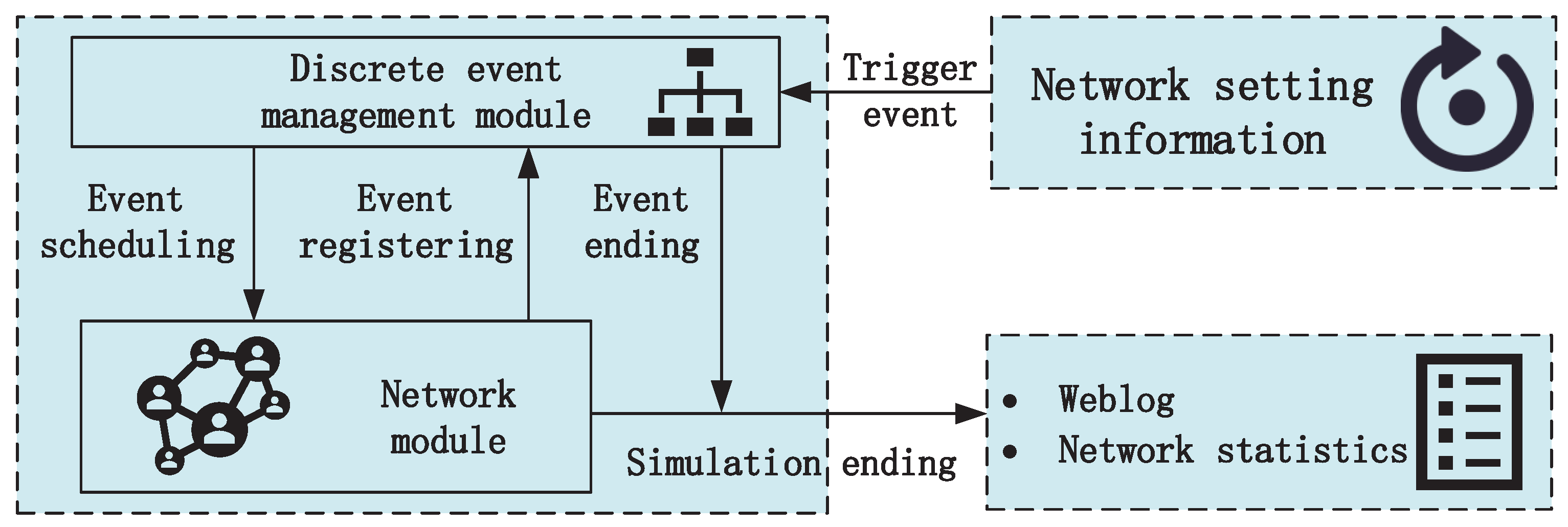
2.1. Discrete-Event Management Module

SPACNet uses a discrete event-driven simulation mechanism, as shown in Figure 2. The discrete-event management module is an important module for promoting the network simulation, and its functions include accessing the event queue and managing event execution. In addition, it is also responsible for scheduling events and managing events in the queue. During the simulation process, the discrete-event management module specifies the simulation time of each event, schedules it sequentially based on the simulation sequence, and submits it to the network model for processing. The network model appends time information and registers the new event with the management module if a new event occurs while processing previous events. After the discrete event is completed, the management module will delete it from the queue and recall the event corresponding to the next simulation time to continue the execution. When the end event is triggered, the SPACNet ends the simulation and outputs the weblog and network statistics, e.g., the packet delivery rate, packet loss rate, and delay. To reproduce the network operation scenario for analysis, the simulation log records all events scheduled by the discrete-event management module according to the simulation time sequence.

2.2. Integrated Environment-Driven UWA Channel Model
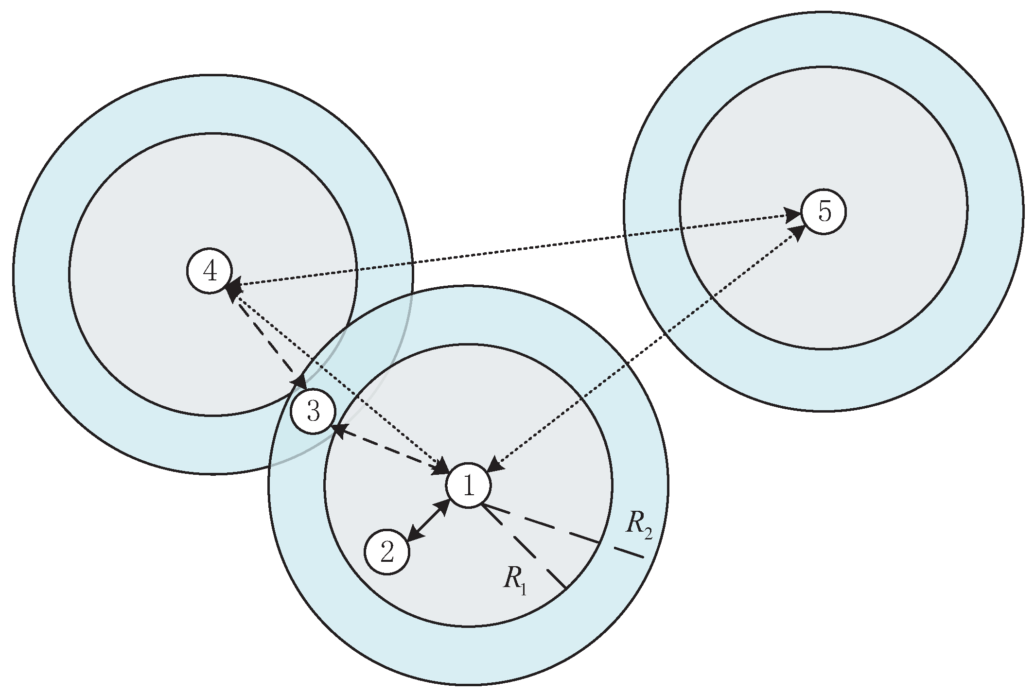
From the perspectives of nodes and links, the communication network system adopts an integrated environment-driven UWA channel model. The environment model defines the parameters of the water area where the network is located and inputs them into the UAC module to simulate the network data transmission process. In addition, based on actual simulation requirements, the network size, topology, and work scenario are defined through the environment-driven UWA channel model, including node location information, external environmental parameters, and link states between nodes.
Considering the time-varying characteristic of underwater acoustic channels, the intensity of each multipath is modeled as a process obeying Gaussian random variation, where a random number with a mean of a ¯ p is superimposed on the time-varying diameter. The channel impulse response h τ , t is represented by the following formula:
h τ , t = p = 1 N p a p t δ τ τ p ,
where t is time, τ p is the time delay of the pth path, N p is the number of multipaths, and δ τ is the Dirac function. Hence, the received signal can be written as follows:
y t = p = 1 N p a p t s t τ p + n t ,
where s t is the transmitted signal and n t is the noise. Then, a Doppler factor is introduced, and Equation (2) can be rewritten as follows:
y t = p = 1 N p a p t s 1 + Δ p t τ p + n t ,
where Δ p = v p c is the Doppler factor in the pth path, v is the relative velocity between transmitter and receiver, and c is the underwater acoustic velocity. To produce a more realistic underwater acoustic channel, Equation (1) between nodes is generated by the Bellhop model based on environmental parameters. The noise and Doppler factor are added in Equation (3). The environment-driven parameters of Equation (3) depend on the environmental parameters of Equation (4), which reflect the true environment.
In practical applications, to unify the form and facilitate the simulation, the strategy of mapping from 3D to 2D was adopted. Only by accurately expressing the interconnection status of links between nodes can a network topology model be established. In the specific implementation process, a N × N × K three-dimensional matrix is constructed in the topology module to store the link distance, boundary information, Doppler factor, and other information between the transmitting node and all receiving nodes. The three-dimensional information matrix can be expressed in Equation (4):
G = g 11 g 12 g 1 N g 21 g 22 g 2 N g N 1 g N 2 g N N ,
g i j = g i j 1 g i j 2 g i j K ,
where g i j k is the k-th environmental parameter from node i to node j, g i j is the total environmental parameters from node i to node j, and G is the total environmental parameters in the network. Notation N is the number of nodes in the network, and K is the number of channel modeling parameters, which is determined by the channel simulator and varies according to the number of input parameters.
In addition, in our designed SPACNet, the Bellhop model and real environmental noise are used to formulate the characteristics of an underwater acoustic channel with high fidelity.

2.3. P2P Node Model

The nodes are the basic units of the simulation network, and mainly include source, sink, transmitter, and receiver nodes. The transmitter and receiver correspond to the transmitting and receiving transducers in the real network. The main parameters of the transducer include directivity, sound source level, etc. The source module is responsible for generating source data and defining the size of the network load and the random method of generating source data. The sink module is responsible for the final receiving data and information statistics. The information flow diagram is shown in Figure 3. It can be seen that a semiphysical simulation can be implemented by incorporating SPACNet and the physical layer.

2.4. State Machine-Based Process Model

The state machine-based process model is an important part of cognitive network simulation platforms. The network protocols conform to the six-tuples of finite state machines, which can be abstracted into state set, initial state, input, action, output, and state transition [34]. The protocol stack based on the state machine can intuitively represent the logical structure of the protocol, and the process model uses the finite state machine to describe the logical behavior of nodes. The state transition process has no aftereffect, which can be modeled by a nonhomogeneous Markov chain, and the finite state space is defined based on the adopted protocol. The one-step transition matrix can be expressed as:
P m = p 11 m p 12 m p 1 N m p 21 m p 22 m p 2 N m p N 1 m p N 1 m p N N m ,
and the one-step transition matrix satisfies Equation (7):
0 p i j m 1 j = 1 N s p i j m = 1 ,
where p i j m is the one-step transition probability of the node from state i to state j at time m, and N s is the total number of states in finite state space. For example, Figure 4 shows the state transition diagram of link quality cognitive routing based on a multiparameter comprehensive evaluation protocol, and the one-step transition matrix can be written as:
P m = p 11 m p 12 m p 13 m p 21 m p 22 m 0 p 31 m p 32 m p 33 m ,
where the state transition probability is related to the actual network running status and network protocols. Note that, because p 23 m = 0 as expressed in (8), in Figure 4, there is no state transition from state 2 to state 3.

3. Multinode UAC Module

The multinode UAC module is one of the important modules of SPACNet. It can not only calculate the actual information parameters of P2P links, such as the bit error ratio (BER), but also provide relevant channel parameters required for the UACNs. In the multinode UAC module, collisions are inevitable, which will have a significant impact on the UACNs; hence, the collision model and the corresponding collision simplification model were established.

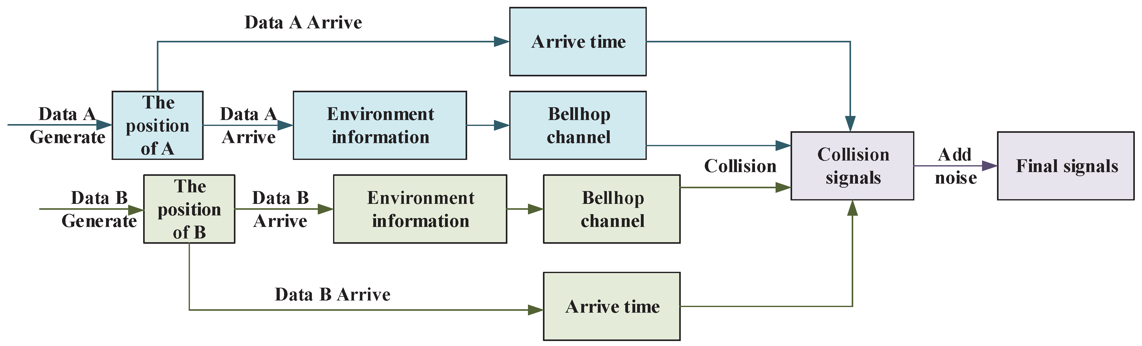
3.1. Collision Model

To simulate the real conflict phenomenon, a P2P transmitted model is used to generate multiple signals for superposition, and the collision model is shown in Equation (9).
y i t = j = 1 , j i N c y j i t τ j i + n i t ,
where τ j i is the transmission delay between node j and node i, and N c is the number of collision nodes.
The detailed process of network data collision in SPACNet is shown in Figure 5. A line denotes the process, while a block denotes signals or parameters. When both nodes A and B transmit signals to node C at the same time, it results in a conflict at node C. When nodes A and B transmit signals, their location information g A C P and g B C P is recorded. When the signals arrive at node C, the output signals y A C and y B C can be calculated according to the underwater acoustic channel model based on the environment information g A C and g B C . Hence, after adding noise, the received collision signal y C t can be obtained by Equation (9). Finally, the demodulation results are uploaded to the data link layer for processing.

3.2. Simplified Collision Model

In a large multinode UACNs simulation, to reduce the computing complexity and improve the simulation efficiency of SPACNet, the data transmission results should be calculated in advance based on the simplified model and fed back to the node model in the form of a table lookup. The actual process of signal conflict in the UACNs can be restored to the greatest extent by using the above method; however, it was found that the computation workload is large and the simulation runs slowly. To improve simulation efficiency further, the underwater acoustic signal transmission module was simplified to reduce invalid and repetitive calculations.
To avoid invalid calculations, a simplified model is used to distinguish the valid transmission range and interference range of nodes. In Figure 6, notation R 1 denotes the valid transmission range, and the destination node can receive the data packet successfully and recover the data information accurately within the R 1 range. The black full line denotes the connection between two nodes. Notation R 2 denotes the interference range, which may affect the normal communication of other nodes during data transmission. The black dashed line denotes the connection between two nodes. Further, the interference interval is the nonoverlapping part of the interference range and the valid transmission range, which is the teal area in Figure 6. Nodes within this range can receive signals from the transmitting node and have the opportunity to successfully demodulate data information, and signals from transmitting nodes will cause interference to the communication of nodes within this area. Hence, for a received node, there is no need to consider the transmitted node if the distance between the transmitted node and the received node is far enough to exceed R 2 . For example, in Figure 6, nodes four and five do not need to be considered when dealing with the received signals of node one.
As we know, in the P2P model, the data can be successfully demodulated if the minimum signal-to-noise (SNR) of the received signals is higher than the detection threshold, which is satisfied by Equation (10):
D T > S L T L N L ,
where D T , S L , T L , and N L are the detection threshold, sound level, transmission loss, and noise level, respectively. Notation D T is based on the physical layer. To account for other node interference in the network, Equation (10) can be rewritten as:
D T > S L T L N L I L ,
where I L is the interference level, which is the sum of the interference levels of all nodes. Notation I L can be defined as:
I L i = j = 1 , j i N I L j ,
where the interference level of one node can be defined as:
I L j r = S L j T L j r N L .
According to the P2P transmitted model [35], T L can be written as:
T L r = n × 10 lg r + α r ,
where r is the propagation distance and the value n is determined by extended propagation conditions. And α is the absorptivity, which can be written as:
α 3.3 × 10 3 + 0.11 f 2 1 + f 2 + 44 f 2 4100 + f 2 + 3.0 × 10 4 f 2 d B / k m ,
To obtain the farthest interference distance R 2 , the farthest from R 2 interference is considered N L , which means I L = 0 . It is obtained by Equation (13) as:
T L R 2 = S L N L .
By combining Equation (14) and Equation (16), the value of R 2 is obtained by Equation (17):
n × 10 lg R 2 + α R 2 = S L N L ,
Then, considering the value of R 1 , T L R 1 can be defined by:
T L R 1 = S L D T I L N L .
By combining Equation (14) and Equation (18), the value of R 1 is obtained by Equation (19):
n × 10 lg R 1 + α R 1 = S L D T I L N L .
It is worth noting that, although the values of R 1 and R 2 can be calculated, the reservation value is essential due to the dynamic underwater environment.

4. Simulation Experiment

To demonstrate the effectiveness of SPACNet, a simulation experiment was conducted that contained 19 child nodes and 2 sink nodes.

4.1. Network Parameters Configuration

The parameters of the simulation experiment are shown in Table 1. The total number of nodes was 21, and the number of sink nodes was 2. A different M-ary DSSS system was applied, and the node communication mode was half-duplex. Moreover, a 15.5 kHz carrier frequency, a 2.35 kHz bandwidth, and a 55.8 b/s data rate after convolutional decoding were used in this simulation experiment. The total runtime of the network was 24 h. The packet generation follows the Poisson distribution λ , and the 1 / λ was set from 100 to 1500 s/packet in the simulation experiment. Note that the specific parameters as given in Table 1 were selected according to the typical marine environmental monitoring scenario of underwater acoustic networks, which feature high transmission reliability and low data load. The deployment location of the simulation marine environmental monitoring UACNs was set to an offshore sea area, corresponding to a shallow water-type channel pattern.
The topology structure of the simulation experiment is shown in Figure 7a, and the initial network state is shown in Figure 7b.
To mimic the real underwater acoustic channel environment of an offshore sea area affected by periodic tide phenomena, artificial time-varying channels were generated by the Bellhop model with a changing depth parameter. Figure 8 shows the channel of node 9, which shows periodical tide-driven time-varying channel characteristics. Moreover, the environmental noise experimentally collected from Xiamen Harbor was adopted as additive noise for the simulation to create a receiving signal with a specific signal-to-noise ratio (SNR).

4.2. Simulation Process

To simulate routing variations caused by an adverse underwater acoustic environment in SPACNet, the total runtime of the network was 24 h, which was divided into two parts. First, the UACNs operated normally for 12 h. Second, nodes 5 and 17 acted as dead nodes and disconnected from the network within the next 12 h. To obtain more accurate simulation results, every λ was simulated 10 times.
Thanks to the cognitive capacity of SPACNet, underwater acoustic channels, which contain environmental information, were easy to input into the physics layer, and the cognitive parameters were also easy to obtain by SPACNet because of the multinode UAC module.

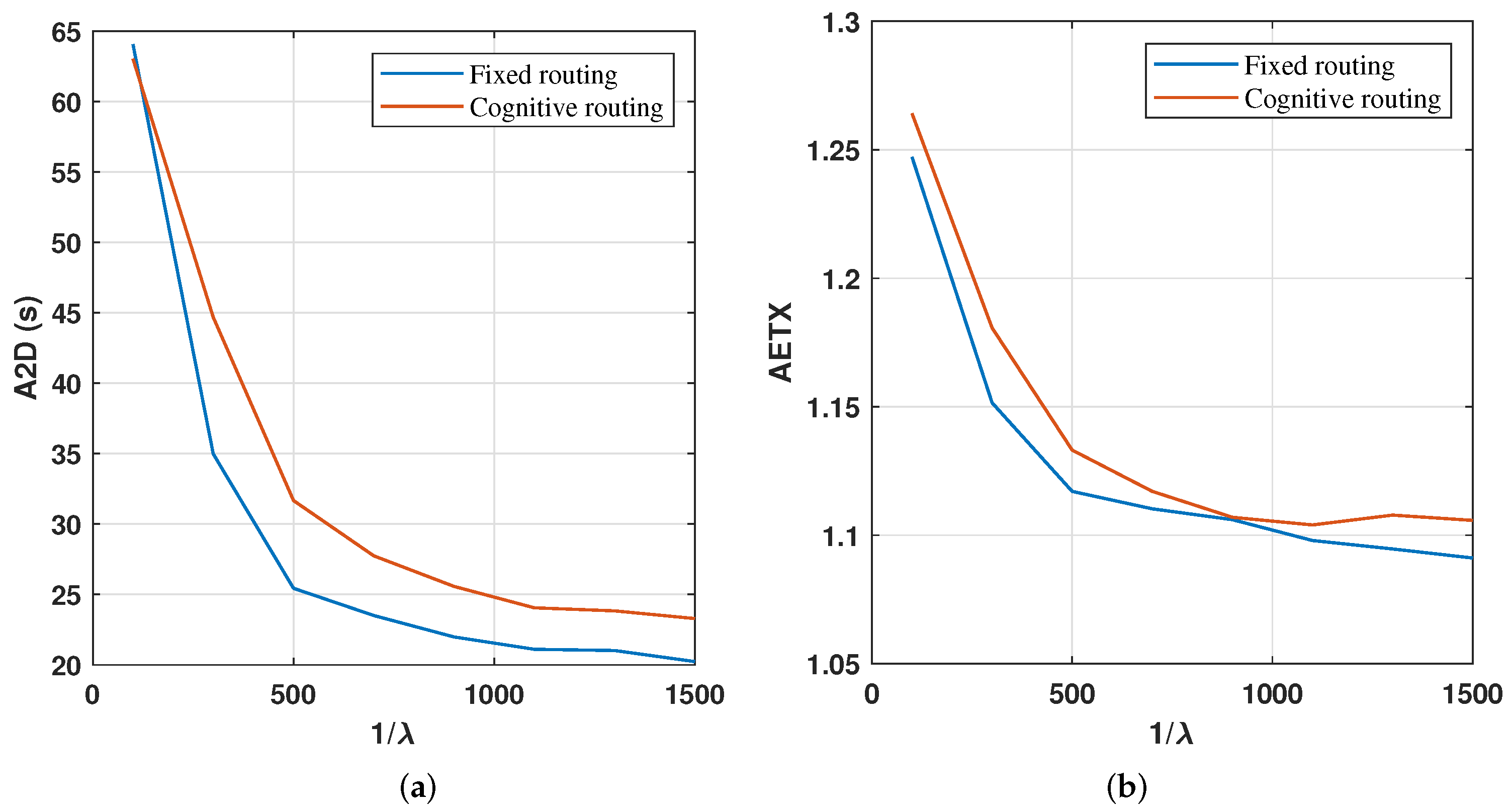
4.3. Results and Analysis

Link quality cognitive routing based on a multiparameter comprehensive evaluation and fixed routing were simulated in the simulation experiment, including the packet delivery rate (PDR), average end-to-end delay (A2D), and average expected transmission count (AETX).
PDR is defined in Equation (20):
P D R = D r / D 0 ,
where D 0 and D r are the total number of data packets generated in the whole network and the number of data packets received by the sink node, respectively.
A2D is defined in Equation (21), which is the average of the total time that a data packet is successfully transmitted from one source node to another, including transmitted delay, relay process delay, wait delay, and collision delay.
A 2 D = d D r t i m e s ( d ) t i m e 0 ( d ) D r ,
where t i m e 0 and t i m e s are the absolute times of a data packet generated in a source node and the data packet received in the sink node.
AETX is defined in Equation (22), which is the average ratio of the total number of data packets transmitted and the data packets received in the sink node.
A E T X = D s D r ,
where D s is the total number of transmitted data packages.
Finally, the simulation results are shown in Figure 9 and Figure 10a,b.
The PDR of cognitive routing was far superior to that of fixed routing, because link failures in fixed routing occurred when nodes 5 and 17 died, while the new relying nodes were selected to transmit packets through cognitive routing. It can be seen that the PDR of both routing protocols increased as the λ decreased, and the decreasing trend was from fast to slow, because the load was the main influencing factor for high λ , while the dead nodes were the main factor for low λ . It can also be seen that the PDR difference between the routing protocols tended to be zero, rapidly increasing as λ decreased, and then roughly remaining the same for low λ . This is because the inevitable P2P transfer time led to cognitive routing that also lost efficacy due to excessive λ .
In view of the A2D and AETX, it can be seen that the value and the tendency were roughly the same for both, and even the fixed route had a slightly superior performance. This is because packets that did not successfully transfer data were not counted in both calculations. In fact, the PDR was the most important network evaluation parameter.
In this simulation experiment, one can observe that the behavior of the cognitive protocol and the fixed routing protocol could be quantitatively evaluated in SPACNet, demonstrating the effectiveness of the proposed simulation platform.

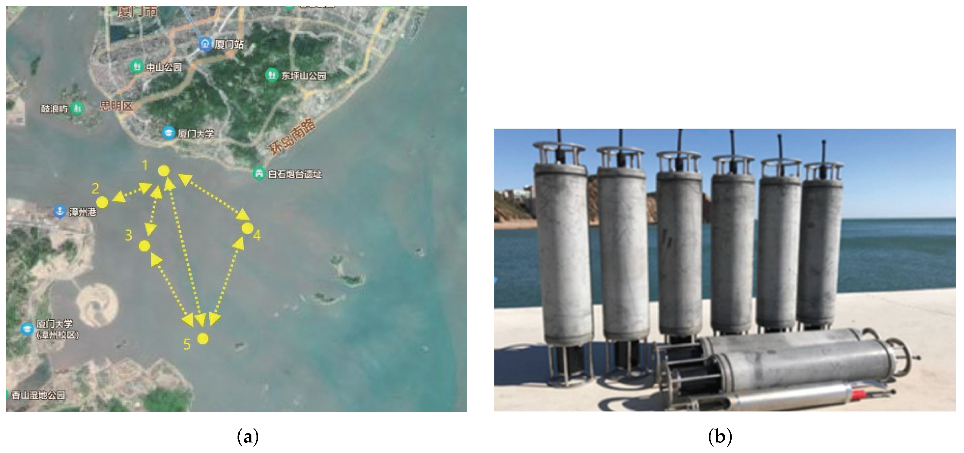
5. Field Experimental Validation

To validate the general consistency between the simulation results obtained via SPACNet and the practical behavior of the physical UACNs, a field test was performed in Xiamen harbor sea area.

5.1. Network Configuration of the Field Experiment

To guarantee the comparability of the field experiment with respect to the simulation, the network parameter configuration of the field experiment was set according to that in simulation, as shown in Table 2. Note that the number of nodes, the network runtime, and the packet generation parameter were different from that of simulation due to practical limitation caused by hardware overheads and field operation costs associated with the trial test.
The location of the field experiment, Xiamen harbor sea area, is a typical shallow water offshore area with an average depth of about 20 m, which is governed by a semidiurnal tide. The topology of the field experimental underwater acoustic network is given in Figure 11a, which consists of five nodes, with the largest distance between adjacent nodes being 5.9 km. The network node adopted for the field UACNs experiment is shown in Figure 11b. To be consistent with the simulation network scenario, the field UACNs was configured to a five-node marine environmental monitoring sensor network with node 1 as the sink node, and the other four nodes as the sensor nodes, as shown in Figure 11. Moreover, to facilitate the comparison with the simulation results, the 24 h running time of the field UACNs was similarly divided into two stages, the first 12 h running in fixed routing mode and the second 12 h running in cognitive routing.

5.2. Results and Analysis

As the purpose of the field UACNs experiment was for general validation of the proposed SPACNet, the PDR was adopted to quantitatively evaluate the network performance of the cognitive routing and the fixed routing during the field test. The resulting PDR of the cognitive routing and fixed routing is provided in Table 3, which reveals that the cognitive routing outperformed the fixed routing with a PDR of 92.5% as compared to 75.1%. Thus, the PDR results obtained from the field network experiment were generally consistent with those of the simulation experiment as yielded by SPACNet. Note that, as the node number of the field test was much smaller than that of the simulation, the field experimental network corresponded to a bigger PDR that the simulation network due to there being much fewer collisions at a similar network load. As regards the reason behind the transmission failures, besides those caused by transmission collisions, the time-varying multipath associated with the adverse shallow water channel was also a key factor, considering that the average SNR of the receiving signal was about 8 dB, which was high enough for the DSSS modulation adopted.

6. Conclusions

Despite the extreme importance of underwater acoustic cognitive networks (UACNs) in extensive marine missions as recognized by the research community and the industry, the lack of convenient simulation platforms hinders research into UACNs as the conventional network simulation platforms are not specially designed to enable cognitive acoustic networking. To facilitate comprehensive performance evaluation of UACNs via a simulation, a novel simulation tool, i.e., SPACNet (simulation platform for acoustic cognitive network), was designed and is presented in this article. It provides effective and efficient support for the application of CNs in underwater environments by saving substantial hardware resources, facilities, and personal resource costs associated with field underwater acoustic network experiments. The design of SPACNet is outlined in detail.
The key difference between cognitive wireless networks and UACNs is the significant difficulties caused by challenging underwater acoustic channels and the diverse underwater acoustic physical layer and network protocol to mitigate them; thus, the capability to sense underwater acoustic channels and accordingly optimize network operation mechanisms is crucial to the design of a simulation platform for UACNs. Specifically, to enable the high-fidelity formulation of underwater acoustic environments, the Bellhop model with a specific marine environmental parameter input was embedded to generate time-varying underwater acoustic channels between network nodes. Moreover, SPACNet builds a protocol programming framework based on state machines, implements the UACNs protocol within this framework, and simulates cross-layer protocols through information exchange between protocol layers. Based on the marine environment-driven multinode underwater acoustic transmission process and the cross-layer protocol that enables information exchange, the behavior of cognitive acoustic networking can be comprehensively evaluated by SPACNet in terms of multiple quantitative network performance indicators.
The effectiveness of the proposed SPACNet in evaluating UACNs was verified by a simulation UACNs consisting of 21 nodes specialized for marine environmental monitoring. Furthermore, a five-node field UACNs similarly configured according to the simulation scenario was deployed in the offshore sea area near Xiamen harbor, the performance of which was then analyzed for comparison with the simulation. For both the simulation and field experiment, with respect to the two different routing schemes, i.e., cognitive routing and fixed routing, the impact of the underwater acoustic channel was adapted to cause different state-transform types under the framework of SPACNet. The corresponding variations of specific routing in the cognitive routing scheme driven by the cognitive network mechanism, thus, verify that the proposed SPACNet is capable of supporting different state-transform types caused by underwater environmental factors. Finally, the general consistency between the results obtained from the SPACNet-based simulation and that obtained from the field UACNs experiment validate the performance of SPACNet.
Note that, as a network simulation platform, it is crucial to provide extensive comparison functions to evaluate the performance of different network schemes, including the newly developed example and that previously proposed. However, because there is no current unified protocol standard or protocol framework for underwater networks, the protocol designs details of different UACNs works are highly diverse. As a result, the practical implementation of UACNs work developed by other authors takes substantial time and efforts. In the future, based on the basic network modules already embedded in SPACNet, we will add more UACNs modules to enable the extensive comparison and evaluation of various UACNs strategies.

Author Contributions

Conceptualization, X.Y. and F.T.; Methodology, X.Y.; Software, S.Z.; Validation, X.Y. and Y.Z.; Formal analysis, X.Y.; Data curation, S.Z.; Writing—original draft, X.Y.; Writing—review & editing, X.Y. and F.T.; Visualization, X.Y. and S.H.; Supervision, D.C.; Project administration, D.C. and F.T.; Funding acquisition, F.T. All authors have read and agreed to the published version of the manuscript.

Funding

This research was supported in part by the National Key Research and Development Program of China (No. 2018YFE0110000), the National Natural Science Foundation of China (No. 11274259, No. 11574258), MEL-RLAB Joint Fund for Marine Science & Technology Innovation (M&R 202303), and the Science and Technology Commission Foundation of Shanghai (21DZ1205500) in support of the present research.

Institutional Review Board Statement

Not applicable.

Informed Consent Statement

Not applicable.

Data Availability Statement

The data presented in this paper are available after contacting the corresponding author.

Conflicts of Interest

The authors declare no conflict of interest.

References

  1. Zhao, N.; Yao, N.; Gao, Z.; Lu, Z. Deep reinforcement learning based time-domain interference alignment scheduling for underwater acoustic networks. J. Mar. Sci. Eng. 2022, 10, 903. [Google Scholar] [CrossRef]
  2. Zhou, Y.; Tong, F.; Yang, X. Research on Co-Channel Interference Cancellation for Underwater Acoustic MIMO Communications. Remote Sens. 2022, 14, 5049. [Google Scholar] [CrossRef]
  3. Mohapatra, A.K.; Gautam, N.; Gibson, R.L. Combined routing and node replacement in energy-efficient underwater sensor networks for seismic monitoring. IEEE J. Ocean. Eng. 2012, 38, 80–90. [Google Scholar] [CrossRef]
  4. Yang, X.; Zhou, Y.; Wang, R.; Tong, F. Research and Implementation on a Real-time OSDM MODEM for Underwater Acoustic Communications. IEEE Sens. J. 2023, 23, 18434–18448. [Google Scholar] [CrossRef]
  5. Jiang, W.; Yang, X.; Tong, F.; Yang, Y.; Zhou, T. A low-complexity underwater acoustic coherent communication system for small AUV. Remote Sens. 2022, 14, 3405. [Google Scholar] [CrossRef]
  6. Zhou, Y.; Diamant, R. A parallel decoding approach for mitigating near–far interference in internet of underwater things. IEEE Internet Things J. 2020, 7, 9747–9759. [Google Scholar] [CrossRef]
  7. Mohsan, S.A.H.; Li, Y.; Sadiq, M.; Liang, J.; Khan, M.A. Recent advances, future trends, applications and challenges of internet of underwater things (iout): A comprehensive review. J. Mar. Sci. Eng. 2023, 11, 124. [Google Scholar] [CrossRef]
  8. Apostolopoulos, P.A.; Tsiropoulou, E.E.; Papavassiliou, S. Cognitive data offloading in mobile edge computing for internet of things. IEEE Access 2020, 8, 55736–55749. [Google Scholar] [CrossRef]
  9. Firozjaei, H.M.; Moghaddam, J.Z.; Ardebilipour, M. A Virtual MIMO Communication for an UAV Enabled Cognitive Relay Network. IEEE Sens. J. 2023, 23, 20267–20274. [Google Scholar] [CrossRef]
  10. Xiao, H.; Wu, C.; Jiang, H.; Deng, L.P.; Luo, Y.; Zhang, Q.Y. Energy-Efficient Resource Allocation in Multiple UAVs-Assisted Energy Harvesting-Powered Two-Hop Cognitive Radio Network. IEEE Sens. J. 2023, 23, 7644–7655. [Google Scholar] [CrossRef]
  11. Li, Z.; Shi, J.; Wang, C.; Wang, D.; Li, X.; Liao, X. Intelligent covert communication design for cooperative cognitive radio network. China Commun. 2023, 20, 122–136. [Google Scholar] [CrossRef]
  12. Morozs, N.; Mitchell, P.D.; Diamant, R. Scalable adaptive networking for the internet of underwater things. IEEE Internet Things J. 2020, 7, 10023–10037. [Google Scholar] [CrossRef]
  13. Luo, Y.; Pu, L.; Mo, H.; Zhu, Y.; Peng, Z.; Cui, J.H. Receiver-initiated spectrum management for underwater cognitive acoustic network. IEEE Trans. Mob. Comput. 2016, 16, 198–212. [Google Scholar] [CrossRef]
  14. Li, X.; Sun, Y.; Guo, Y.; Fu, X.; Pan, M. Dolphins first: Dolphin-aware communications in multi-hop underwater cognitive acoustic networks. IEEE Trans. Wirel. Commun. 2016, 16, 2043–2056. [Google Scholar] [CrossRef]
  15. Chaudhary, R.; Sethi, S.; Keshari, R.; Goel, S. A study of comparison of Network Simulator-3 and Network Simulator-2. Int. J. Comput. Sci. Inf. Technol. 2012, 3, 3085–3092. [Google Scholar]
  16. Jiang, W.; Tong, F. Exploiting sparsity for underwater acoustic sensor network under time-varying channels. IEEE Internet Things J. 2021, 9, 2859–2869. [Google Scholar] [CrossRef]
  17. Bian, D.; Kuzlu, M.; Pipattanasomporn, M.; Rahman, S.; Wu, Y. Real-time co-simulation platform using OPAL-RT and OPNET for analyzing smart grid performance. In Proceedings of the 2015 IEEE Power & Energy Society General Meeting, Denver, CO, USA, 26–30 July 2015; IEEE: New York, NY, USA, 2015; pp. 1–5. [Google Scholar] [CrossRef]
  18. Xie, P.; Zhou, Z.; Peng, Z.; Yan, H.; Hu, T.; Cui, J.H.; Shi, Z.; Fei, Y.; Zhou, S. Aqua-Sim: An NS-2 based simulator for underwater sensor networks. In Proceedings of the OCEANS 2009, Bremen, Germany, 11–14 May 2009; IEEE: New York, NY, USA, 2009; pp. 1–7. [Google Scholar] [CrossRef]
  19. Martin, R.; Zhu, Y.; Pu, L.; Dou, F.; Peng, Z.; Cui, J.H.; Rajasekaran, S. Aqua-sim next generation: A NS-3 based simulator for underwater sensor networks. In Proceedings of the 10th International Conference on Underwater Networks & Systems, Arlington, VA, USA, 22–24 October 2015; pp. 1–2. [Google Scholar] [CrossRef]
  20. Zuba, M.; Jiang, Z.; Yang, T.; Su, Y.; Cui, J.H. An advanced channel framework for improved underwater acoustic network simulations. In Proceedings of the 2013 OCEANS, San Diego, CA, USA, 24–26 September 2013; IEEE: New York, NY, USA, 2013; pp. 1–8. [Google Scholar] [CrossRef]
  21. Zuba, M.; Song, A.; Cui, J.H. Exploring parabolic equation models for improved underwater network simulations. In Proceedings of the 2014 Underwater Communications and Networking (UComms), Sestri Levante, Italy, 3–5 September 2014; IEEE: New York, NY, USA, 2014; pp. 1–5. [Google Scholar] [CrossRef]
  22. Masiero, R.; Azad, S.; Favaro, F.; Petrani, M.; Toso, G.; Guerra, F.; Casari, P.; Zorzi, M. DESERT Underwater: An NS-Miracle-based framework to DEsign, Simulate, Emulate and Realize Test-beds for Underwater network protocols. In Proceedings of the 2012 Oceans, Yeosu, Republic of Korea, 21–24 May 2012; IEEE: New York, NY, USA, 2012; pp. 1–10. [Google Scholar] [CrossRef]
  23. Campagnaro, F.; Francescon, R.; Guerra, F.; Favaro, F.; Casari, P.; Diamant, R.; Zorzi, M. The DESERT underwater framework v2: Improved capabilities and extension tools. In Proceedings of the 2016 IEEE Third Underwater Communications and Networking Conference (UComms), Lerici, Italy, 30 August–1 September 2016; IEEE: New York, NY, USA, 2016; pp. 1–5. [Google Scholar] [CrossRef]
  24. Petrioli, C.; Petroccia, R.; Potter, J.R.; Spaccini, D. The SUNSET framework for simulation, emulation and at-sea testing of underwater wireless sensor networks. Ad Hoc Netw. 2015, 34, 224–238. [Google Scholar] [CrossRef]
  25. Martins, R.; de Sousa, J.B.; Caldas, R.; Petrioli, C.; Potter, J. SUNRISE project: Porto university testbed. In Proceedings of the 2014 Underwater Communications and Networking (UComms), Sestri Levante, Italy, 3–5 September 2014; IEEE: New York, NY, USA, 2014; pp. 1–5. [Google Scholar] [CrossRef]
  26. Cruz, N.A.; Ferreira, B.M.; Kebkal, O.; Matos, A.C.; Petrioli, C.; Petroccia, R.; Spaccini, D. Investigation of underwater acoustic networking enabling the cooperative operation of multiple heterogeneous vehicles. Mar. Technol. Soc. J. 2013, 47, 43–58. [Google Scholar] [CrossRef]
  27. Petroccia, R.; Spaccini, D. A back-seat driver for remote control of experiments in underwater acoustic sensor networks. In Proceedings of the 2013 MTS/IEEE OCEANS, Bergen, Norway, 10–14 June 2013; IEEE: New York, NY, USA, 2013; pp. 1–9. [Google Scholar] [CrossRef]
  28. Zeng, X.; Luo, Z.; Chen, F.; Yu, H.; Ji, F.; Guang, Q. An ns-3 compatible emulation framework for underwater acoustic network. In Proceedings of the 13th International Conference on Underwater Networks & Systems, Shenzhen, China, 2–4 December 2018; pp. 1–5. [Google Scholar] [CrossRef]
  29. Luo, H.; Wu, K.; Ruby, R.; Hong, F.; Guo, Z.; Ni, L.M. Simulation and experimentation platforms for underwater acoustic sensor networks: Advancements and challenges. ACM Comput. Surv. (CSUR) 2017, 50, 1–44. [Google Scholar] [CrossRef]
  30. Bai, W.G.; Wang, H.Y.; Zhao, R.Q. Modeling underwater time-varying acoustic channel using opnet. Appl. Mech. Mater. 2013, 263, 1178–1183. [Google Scholar] [CrossRef]
  31. Petroccia, R.; Spaccini, D. Comparing the SUNSET and DESERT frameworks for in field experiments in underwater acoustic networks. In Proceedings of the 2013 MTS/IEEE OCEANS, Bergen, Norway, 10–14 June 2013; IEEE: New York, NY, USA, 2013; pp. 1–10. [Google Scholar] [CrossRef]
  32. Casari, P.; Tapparello, C.; Guerra, F.; Favaro, F.; Calabrese, I.; Toso, G.; Azad, S.; Masiero, R.; Zorzi, M. Open source suites for underwater networking: WOSS and DESERT underwater. IEEE Netw. 2014, 28, 38–46. [Google Scholar] [CrossRef]
  33. Zhu, Y.; Le, S.; Pu, L.; Lu, X.; Peng, Z.; Cui, J.H.; Zuba, M. Aqua-Net Mate: A real-time virtual channel/modem simulator for Aqua-Net. In Proceedings of the 2013 MTS/IEEE OCEANS, Bergen, Norway, 10–14 June 2013; IEEE: New York, NY, USA, 2013; pp. 1–6. [Google Scholar] [CrossRef]
  34. Yan, Z.; Jiang, H.; Li, B.; Yang, M. A Flowchart Based Finite State Machine Design and Implementation Method for FPGA. In Proceedings of the IoT as a Service: 6th EAI International Conference, IoTaaS 2020, Xi’an, China, 19–20 November 2020; Proceedings 6. Springer: Berlin/Heidelberg, Germany, 2021; pp. 295–310. [Google Scholar] [CrossRef]
  35. Lou, Y.; Ahmed, N. Underwater Communications and Networks; Springer: Berlin/Heidelberg, Germany, 2022. [Google Scholar]
Figure 1. Three-layer model and framework of SPACNet. (a) Three-layer model of SPACNet. (b) Framework of the SPACNet.
Jmse 11 01827 g001
Figure 2. Discrete event-driven simulation mechanism.
Jmse 11 01827 g002
Figure 3. Node model of the SPACNet.
Jmse 11 01827 g003
Figure 4. State machine-based process model.
Jmse 11 01827 g004
Figure 5. Collision model of SPACNet.
Jmse 11 01827 g005
Figure 6. Schematic diagram of node transmission range and interference range.
Jmse 11 01827 g006
Figure 7. Topology and initial route of the simulation experiment. (a) Network topology. (b) Initial route.
Jmse 11 01827 g007
Figure 8. A time-varying simulation channel in the simulation experiment.
Jmse 11 01827 g008
Figure 9. PDR result of the simulation experiment.
Jmse 11 01827 g009
Figure 10. Results of the simulation experiment. (a) A2D. (b) AETX.
Jmse 11 01827 g010
Figure 11. The topology of the field UACNs and the network nodes adopted. (a) The topology of the field UACNs. (b) Network nodes adopted.
Jmse 11 01827 g011
Table 1. Parameters of the simulation experiment.
ParameterValue
Number of nodes21
Number of sink nodes2
Transducer directivityOmnidirectional
Modulation systemDifferent Mary-DSSS
Node communication modeHalf-duplex
Carrier frequency (kHz)15.5
Bandwidth (kHz)2.35
Data rate after channel decoding (b/s)55.8
Maximum number of retransmissions3
Runtime of network (h)24
Packet generation (s/packet)100–1500
Table 2. Parameters of the field experiment.
ParameterValue
Number of nodes5
Number of sink nodes1
Transducer directivityOmnidirectional
Modulation systemMary-DSSS
Node communication modeHalf-duplex
Carrier frequency (kHz)15.5
Bandwidth (kHz)2.35
Data rate after channel decoding (b/s)55.8
Maximum number of retransmissions3
Runtime of network (h)24
Packet generation (s/packet)600
Table 3. PDR results of the field experiment.
Network Routing ModePDR
Cognitive routing92.5%
Fixed routing75.1%
Disclaimer/Publisher’s Note: The statements, opinions and data contained in all publications are solely those of the individual author(s) and contributor(s) and not of MDPI and/or the editor(s). MDPI and/or the editor(s) disclaim responsibility for any injury to people or property resulting from any ideas, methods, instructions or products referred to in the content.

