1. Introduction
Global demand for fish products continues to grow due to population increase. However, capturing fish has become unsustainable due to overfishing, and 90% of wild captured species are already overfished or fully fished with no potential for increases in production [
1,
2,
3,
4]. On the other hand, farmed fish production has shown impressive growth over the past three decades to fill the gap between fish demand and production [
5]. Most marine fish farms are primarily located in sheltered, shallow nearshore waters for safe operation, easy access, and quick transportation. However, in recent years, the annual growth rate of farmed fish production is slowing due to public and environmental opposition to water, seabed and shoreline pollution, and competing uses of sheltered sea space such as shipping, water leisure activities, conservation, and tourism. In response to these criticisms and constraints, offshore fish farming is gaining traction as an alternative solution. Moreover, offshore sites offer larger water space, better water quality, cooler temperatures and better waste dispersion from deeper waters [
6], less sea lice infestation [
7], stronger waves, and higher current speeds [
8]. Moving fish farms offshore, however, poses several challenges that include having to contend with a harsher sea environment, an uncertain environment for the farmed fish, operational requirements regarding workers’ safety and support vessels, and the lack of experience and standards in designing offshore fish pens [
9]. The most challenging aspect of offshore fish farming is the survivability of the fish pen and the well-being of fish during severe storms that are accompanied by huge surface waves, winds, and shear current actions.
Two contrasting design philosophies for offshore fish pens have emerged due to the highly energetic offshore environment and deep water. One design philosophy is to make a fish pen with significant size, rigidity, and strength to withstand the strong waves, currents, and winds [
10]. The pens with large net depths allow fish to swim to the pen bottom as the cultured water volume contracts under strong waves passing through the pen. Examples of such fish pens are Ocean Farm 1 [
11,
12], Havfarm 1 [
13], Shenlan 1 [
14], Zhenyu 1 [
10], and Dehai 1 [
15]. These large offshore fish pens have been built in China with steel as the preferred structural material. They have a very high CAPEX (for example, the Norwegian Ocean Farm 1 costs USD 120 million) and OPEX to monitor and maintain the structure and net in good condition, as any failure would lead to large losses since the pens hold over a million fish. The other design philosophy is to have smaller, flexible, and submergible fish pens to dodge the powerful surface waves during extreme weather events, making them storm-proof. Examples of such fish pens are SubFlex [
16,
17], SeaStation [
18], and Impact 9 submersible pens [
19]. This kind of fish pen is often constructed from high-density polyethylene (HDPE) and possesses a ballasting system to submerge the pen and to re-float it to the water surface [
17,
20]. It is important to determine the optimum submerged depth to save ballasting cost and time for re-float. As these structures are flexible, hydroelastic analysis must be performed for design.
The Blue Economy Cooperative Research Centre (BECRC) in Australia has commissioned a research project on developing a novel fish pen for offshore sites. Based on a systematic design development approach, the fish pen called SeaFisher has emerged as a cost-effective design, as it follows the second design philosophy of being flexible and submergible. This paper presents the engineering design details and hydroelastic analysis of the SeaFisher. The layout of this paper is as follows:
Section 2 presents a description of the SeaFisher;
Section 3 gives the material selection and properties;
Section 4 deals with the sizing of SeaFisher components based on a hydrostatic analysis;
Section 5 lists the environmental loads considered for the analysis;
Section 6 presents the simulation model and hydroelastic analysis of the fish pen by using AquaSim under different wave loads representing operating limits and extreme conditions, as well as at various submerged depths;
Section 7 gives the hydroelastic responses of the SeaFisher under different sea-state conditions;
Section 8 suggests some information for practical design refinements of the SeaFisher, and
Section 9 presents the conclusions and future work on the SeaFisher design.
2. Description of the SeaFisher
Figure 1 shows an isometric view of the SeaFisher. The modular SeaFisher design may take on any 2 ×
n array of cubic pens with a side length of 20 m. For the present study, we shall assume a 2 × 6 array (i.e.,
n = 6); wherewith the entire SeaFisher measures 120 m × 40 m × 20 m (with a farming water volume of 96,000 m
3). Assuming a stock density of 15 kg/m
3, the SeaFisher can accommodate about 288,000 mature 5 kg salmons.
The structural frame of SeaFisher is made from high-density polyethylene (HDPE) pipes as shown in
Figure 1 (13). HDPE is selected as it possesses a relatively high modulus of elasticity and high resistance to impact among polymer materials [
21]. Beveridge [
22] highlighted that HDPE is resistant to rotting and weathering, can be easily shaped into different forms, and proves to be a cost-effective option when procured in large quantities compared to alternative materials. As the HDPE is lighter than seawater, it is necessary to fill the HDPE pipes with ballasting water and permanent fillers (e.g., sand, seawater) to keep the SeaFisher submerged in the water.
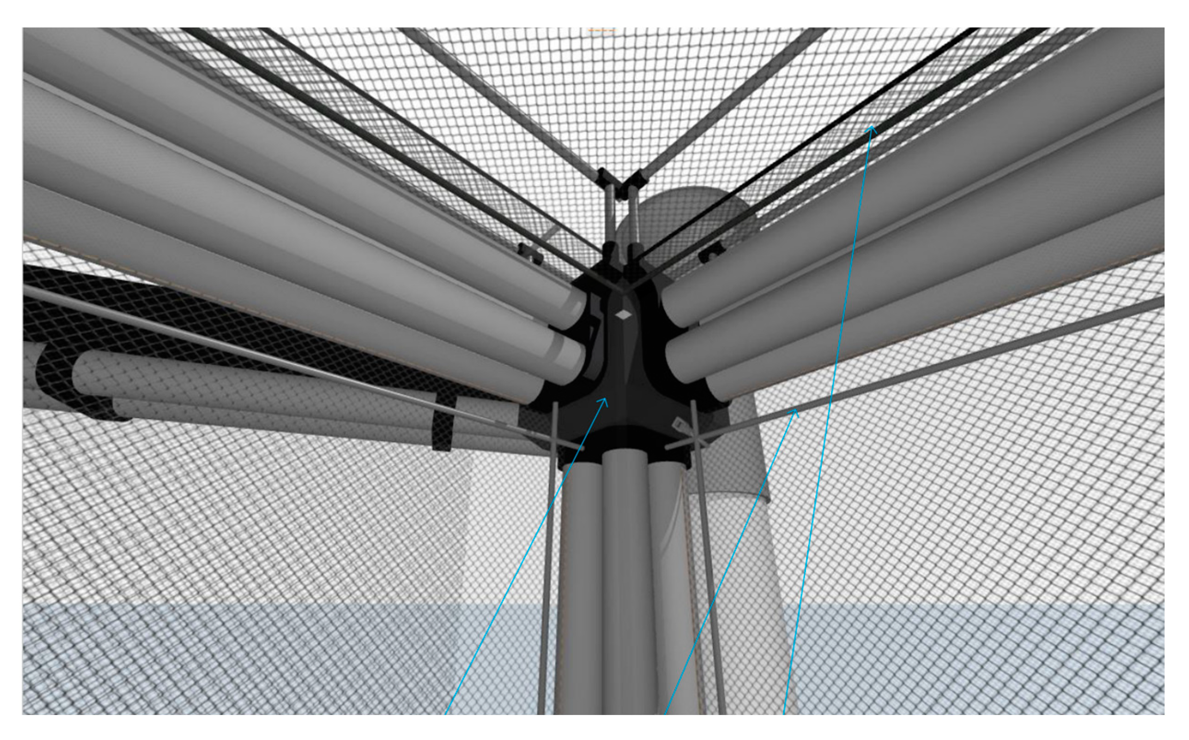
The HDPE connection brackets and connector pods, as shown in
Figure 1 (11–12), are used to hold together a bundle of four pipes arranged in a 2 × 2 array, and these brackets are spaced at 4 m apart. The number of connection brackets may be altered to obtain the desired flexibility of the frame members of the fish pen. At the top surface of the fish pen frame, handrails and a walkway (1.2 m wide) are installed as shown in
Figure 1 (7–8).
The top three bundles of continuous longitudinal HDPE pipes will be used for the ballasting pipes. These ballasting pipes allow the adjustment of the air to seawater ratio for the submergence and floatation of the SeaFisher, thereby ensuring its survivability and fish well-being in severe storms.
To initiate the submerging process, the pressure-sensitive valves located at the front ends of these ballasting pipes are opened by remote control. To utilize the siphoning effect to fill seawater into the top longitudinal ballasting pipes from the open valves, a portion of the front ballasting pipes (extended out of the first fish pen) are bent downwards (see
Figure 1 (6)). Moreover, there are 14 intermediate buoys, guide lines, and bottom weights to keep the submerged SeaFisher at the assigned depth (See
Figure 1 (14–15)). In this concept design of the SeaFisher, the deepest submerged depth is limited to 20 m to coincide with the maximum spacing between adjacent intermediate buoys in the longitudinal direction. As the SeaFisher weathervanes, all the buoys will move in the same direction and, thus, there will be no possible entanglement of ropes. In the transverse direction, the lines are spaced 40 m apart and, hence, there is no way that the ropes can be entangled.
Once the storm has passed, a specialized support vessel equipped with air compressor units will inject compressed air into the rear end of the ballasting pipes connected with the inlet air vents, which are held by three aft buoys (see
Figure 1 (16)) to displace the ballast water; thereby, the SeaFisher is enabled to resurface.
The SeaFisher’s bow is equipped with a rigid, angular-shaped shield made from HDPE mat. This shield has a height of 11.5 m with 1.5 m above the water surface, 44 m in total inclined length, and 40 mm thickness (see
Figure 1 (5)). Its primary purpose is to protect the SeaFisher from the direct impact of floating debris, as well as to provide a streamlined shape to reduce drag forces arising from waves and surface currents.
The Kikkonet [
23] is selected for the fish pen net. As depicted in
Figure 1 (9), Kikkonet is a hexagonal double-twisted mesh manufactured from polyethylene terephthalate (PET), renowned for its exceptional strength, lightweight nature, and antibiofouling characteristics. The versatility of Kikkonet allows for its widespread application in both marine and terrestrial environments, such as Ocean Farm 1 and Innovasea SeaStation fish pens. For the SeaFisher, the net is attached to the HDPE frame structure. In order to strengthen and stiffen the frame structure and the Kikkonet, a diagrid rod system is installed as shown in
Figure 1 (10). The diagrid is made of glass fibre-reinforced polymer (GFRP), which is a durable but lightweight material used for marine structures. The diagrid rods will be tied with the Kikkonet panel of 20 m × 20 m to prevent not only net deformation but also possible invasions from huge wild predators.
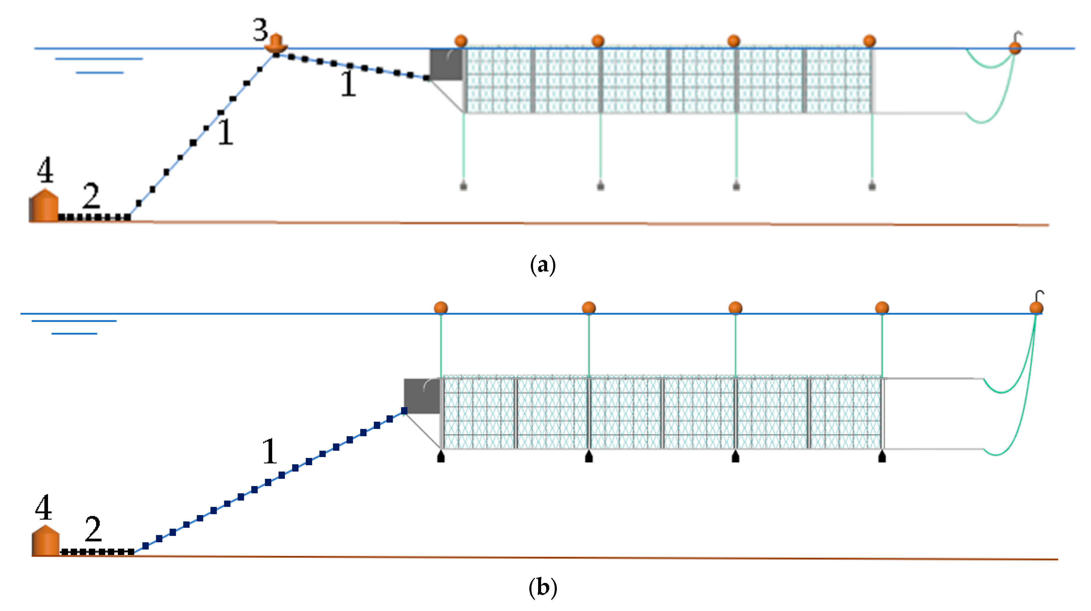
The SeaFisher is kept in place by using a single point mooring (SPM) system (see
Figure 1 (1–4)) that allows the SeaFisher to behave like a weathervane to minimize the environmental forces and possible ship collision forces, and also for better dispersal of waste over a larger sea space. This SPM system consists of a suction anchor, studlink chains, a front buoy, and hawser. The studlink chains are used to connect the hawser to a suction anchor embedded in the seabed. The length of the studlink chains was considered to be 1/3 of total mooring line to provide a sufficient holding mass for the SeaFisher. The front buoy is arranged to keep the hawser near the water surface so that one can easily disengage the SeaFisher from its mooring system when it needs to be towed away (see
Figure 2a). The front buoy is equipped with a winch that can be either mechanically or manually operated, allowing for the extension of the connecting line to the hawser so that it can work as a marking buoy when the SeaFisher is under water, as well as mitigating adverse mooring forces (e.g., lifting force during the submerged state) transmitted to the SeaFisher (see
Figure 2b).
3. Material Properties of SeaFisher Components
Table 1 and
Table 2 show the chosen materials and properties of the SeaFisher’s fish pen pipes and Kikkonet, respectively.
Table 3 summarizes the material and geometrical properties of the hawser and studlink chain for the mooring system, diagrid rod for reinforcement of the fish pen frames and nets, and guide line connected between the intermediate buoys and the bottom weights. Note that the material properties of hawser, studlink chain and diagrid rod are taken from Lankhorst [
24], DNV [
25,
26], and Khan et al. [
27], respectively. The Young’s modulus of GFRP used for the diagrid rod was taken from compression testing results of a GFRP rod from Khan et al. [
27], which is lower than tensile testing results, to be conservative.
The hawser used in this study is constructed with a nylon sheath over a braided hollow core, which has 32 core strands and 64 sheath strands. The hawser was modelled in the analysis model by using truss elements with the solid cross-sectional area calculated from its circular diameter and Young’s modulus, as defined in
Table 3. The studlink chain is made from steel. In the analysis model, it was modelled as truss elements with a solid cross-sectional area calculated from an equivalent diameter specified according to DNV-OS E301 [
26] and Young’s modulus of steel, as defined in
Table 3. As for the GFRP diagrid, it was modelled as truss elements with a solid cross-sectional area calculated from the diameter of the rod and the Young’s modulus given in
Table 3. Note that the guide lines and their dynamic actions were not incorporated in the hydrostatic and hydroelastic analyses as the dive guide system is assumed to be a separate system that does not directly contribute to the total mass or buoyancy of the SeaFisher.
4. Sizing of SeaFisher Components
Each frame member for the cubic fish pen unit of SeaFisher comprises a bundle of four HDPE pipes connected by HDPE brackets and a special connector pod, as shown in
Figure 3. The integration of bundled HDPE pipes offers several advantages in fish pen construction. The smaller pipes being in a bundle facilitates easy handling, transportation, construction, and repair; allows for modularity and scalability in construction; provides additional redundancy and enhance safety as the remaining pipes can still provide structural support in the event of the failure of one pipe; allows ease of customization as the diameters and wall thicknesses may be tailored to produce the desired member’s properties; is cost-effective since smaller pipes are more readily available than a single expensive large pipe; and reduces material wastage when cutting the pipes to appropriate lengths. Nevertheless, caution has to be exercised, particularly as the significance of the connecting system becomes more pronounced in response to the structural dynamics during extreme weather conditions. Therefore, it is imperative to conduct a comprehensive investigation into the connection details and perform a local structural assessment. Also, the gaps between bundled pipes might create more surface for biofouling organisms to grow on, which necessitates increased maintenance costs and environmental impacts.
In determining the pipe size, we took into consideration the operational requirement of providing at least a 1.2 m walkway width, the hydrostatic equilibrium of the SeaFisher, sufficient structural stiffness against axial and bending stresses, and the minimization of the total mass of the SeaFisher, including ballasting and permanent filler masses for cost-effectiveness.
To maintain stable hydrostatic equilibrium in a floating condition, the total weight of the SeaFisher shall be made equal to the total buoyancy force, and its centre of buoyancy will lie above its centre of gravity [
28]. To achieve a better hydro-stability condition, individual frame components were defined by different weights in water conditions such that the following conditions apply:
- (1)
Positive condition: buoyancy force—weight > 0;
- (2)
Neutral condition: buoyancy force—weight 0;
- (3)
Negative condition: buoyancy force—weight < 0.
By adjusting pipe size and permanent filler density, top frame members were assigned to be in the positive condition, bottom frame members to be in the negative condition, and vertical frame members were adjusted to be in the neutral condition. As a result, the SeaFisher’s centre of buoyancy is always kept above its centre of gravity, regardless of the operating states, preventing it from capsizing.
Based on the aforementioned considerations, hydrostatic analyses were carried out to find an appropriate pipe dimension, ballasting mass, and filler density by using the following steps:
Step 1. Select the outer diameter (O.D.), wall thickness, and corresponding standard dimension ratio (SDR, a ratio between O.D. and wall thickness) ranges from the HDPE product lineup of VINIDEX [
29] that produces HDPE pipes according to the Australian and New Zealand Standard [
30].
Step 2. Consider top longitudinal ballast pipes filled with (i) air at the surface state, and (ii) seawater at the submerged state, vertical pipes filled with seawater, and bottom pipes filled with a specific gravity filler ranging from 1 to 2 regardless of the operating states.
Step 3. Calculate the total weight and buoyant force of the SeaFisher.
Step 4. Increase the bottom filler specific gravity (within the limited range) and/or decrease the thickness of pipes (within product lineup) until SeaFisher achieves a hydrostatic equilibrium condition.
Step 5. Evaluate all possible options and choose the optimal option that has the least total mass.
After performing the aforementioned hydrostatic analysis, pipes with O.D. 500 mm and 45 mm wall thickness (SDR 11) were chosen as the base pipe system for the frame members for the SeaFisher. However, a thicker wall thickness of 55 mm was assigned for the transverse pipes because these pipes must be emptied when the SeaFisher is submerged. This requires more strength and stiffness due to a higher local bending moment when compared to other pipes filled with ballast water or permanent filler (see
Table 4).
When the SeaFisher is submerged, maintaining a slight negative buoyancy condition (where the total weight slightly exceeds the total buoyant force) is desirable to keep the submerged structure in a stable condition under the water, similar to other submerged fish case designs, such as SubFlex [
17]. However, there should be a means to prevent the submerged structure from sinking further than a prescribed submerged water depth. Therefore, a dive guide system consisting of 14 intermediate buoys, guide lines, and bottom weights was introduced to keep the SeaFisher at the required water depth. However, the dive guide system was not considered in the hydrostatic calculations, as it is a separate system that does not directly contribute to the total mass or buoyancy of the SeaFisher.
Note that the hydrostatic analyses did not account for the weight and buoyancy generated by the connecting brackets and connector pods. This ignorance is because connecting members are made of a solid mould HDPE, which has a density equivalent to that of seawater, and their dimensions are relatively small and their weight contribution is negligible as compared to the other members.
Table 4 shows hydrostatic parameters for the individual components of the SeaFisher.
Based on the hydrostatic analysis, it is found that the permanent filler density required for the bottom pipes is equivalent to the density of sand (between 1520 to 1680 kg/m
3), which is a good filler material due to its fine particles.
Table 5 shows different ballast masses and displacement masses (i.e., buoyant mass) of the SeaFisher at surface, 10 m, and 20 m submerged states. When the SeaFisher is fully submerged, the total displacement mass increases because it is assumed that the entire section of the top frame contributes to buoyancy, whereas only half a section of the top frame contributes to buoyancy when the SeaFisher floats at the water surface. From the hydrostatic equilibrium calculation, the 20 m submerged case requires two times more ballast mass than the 10 m submerged depth condition. Note that the structure mass in
Table 5 includes permanent filler masses in the vertical and bottom pipes.
5. Environmental Design Loads
The potential site for the deployment of the SeaFisher is at an exposed site in the Storm Bay of Tasmania, Australia, as shown in the red circle in
Figure 4. The environmental data at the site were supplied by Huon Aquaculture (a partner of Blue Economy CRC) and are shown in
Table 6. Note that the wave condition for the extreme weather was estimated based on a 50-year return period according to Huon Aquaculture’s practice for designing fish pens.
For the hydroelastic analysis, the headings of wave and current loads were assumed to be directed towards the front of the SeaFisher, as this represents the worst scenario for maximum drag force, mooring tension force, and the hydroelastic response of the SeaFisher.
6. AquaSim Model and Hydroelastic Analysis
Hydroelastic analyses on the SeaFisher under wave and current actions were performed by using AquaSim [
31]. Developed by the Norwegian company Aquastructures AS, AquaSim is an advanced analysis tool for hydroelastic analysis of flexible marine structures, especially suitable for fish pens. AquaSim enables a finite element analysis in a time domain with consideration for nonlinearities from large translations and rotations coupled with flexible parts. AquaSim is able to model the pen nets with the specification of the net twine thickness and mask width to determine the hydroelastic response of the flexible fish pen and interactive responses between moorings and structures, as well as to provide a diverse post-processing display of results. AquaSim can analyse the structural response of a fish pen under the combined action of waves, currents, and wind. The fluid force is calculated from Morison’s equation for the submerged components. For floating components near the water surface, the strip theory is applied. The hydrodynamic interactions are determined by calculating the Froude–Kryloff force, diffraction force, and wave drift force [
31].
The hydroelastic analysis of the fish pen involves the selection of appropriate finite element types for each component. According to the AquaSim user manual [
32], beam elements are suitable for structural members that can withstand torsion, bending, and axial loads, especially those with complex cross sections, like I-beams and floating collars. Truss elements can be used for members that primarily bear axial loads (either tensile or compressive forces), such as wires, ropes, and chains. Membrane elements can be used for nets.
Based on the selected dimensions and material from the hydrostatic analyses, the members of SeaFisher were modelled with the respective element types, considering the hydrodynamic interactions with fluid. As a result, frame members and bow frames were modelled using beam elements, while membrane-type shell elements were employed for the front shield mat. Kikkonet was modelled using a special membrane element for the net grid, and diagrid rods and mooring lines (hawser and studlink chain) were modelled with truss elements. Note that a bundle of pipes was modelled by a single equivalent beam element with the same mechanical properties, and the pipes were assumed to be rigidly connected at the joints. Moreover, AquaSim’s default drag coefficient of 1.2 was adopted for beam and truss elements when calculating the drag forces from the Morison equation. A future study will calibrate the drag coefficient by conducting a physical model test in a towing tank.
Figure 5 shows the SeaFisher model and
Table 7 presents the element details that form the analysis inputs in AquaSim.
Figure 6 shows detailed dimensions of the bow frame structure for the shield mat.
The front buoy can affect the SeaFisher’s mooring and motion responses when it is at the surface condition. In order to model the buoy, a nodal spring element was used with a vertical stiffness corresponding to the water plane area of the buoy. As an initial design, the vertical stiffness of a 5 m diameter circular buoy was considered in the analyses. On the other hand, the nodal spring element was removed from the submerged models, as the buoy is designed to have an extended connecting line to the hawser to mitigate any possible intervention to the submerged SeaFisher. All models have a fixed end on the last truss element of the studlink chain whose end is assumed to be held firmly in the seabed by a suction anchor.
Figure 7 shows the schematics of mooring modelling considered for the surface and submerged states.
For the SeaFisher’s hydroelastic analysis in the time domain, we considered three different SeaFisher’s positions: at the water surface, at 10 m below the water surface, and at 20 m below the water surface. To demonstrate the 10 m and 20 m submerged states from the surface state model, an adjustable mass density of top ballasting pipes was considered corresponding to the ballast mass given in
Table 5. AquaSim allows linear increments of hydrostatic loads until the model obtains the hydrostatic equilibrium condition. Once the model achieves hydrostatic equilibrium, dynamic loads will be generated based on the user inputs. For simplicity of analysis and consideration of the extreme limits of design, a series of regular waves were considered to represent the maximum wave height that can statistically occur at the given significant wave height in
Table 6. According to the Norwegian Standard of fish farms [
33], the Australian Bureau of Meteorology [
34], and the AquaSim user manual [
32], the maximum wave height can be estimated to be about 1.9 times the significant wave height. With this estimation, analysis load sets for normal and extreme conditions were made within AquaSim to have regular waves with the maximum wave height and peak wave period together with constant speed current force. The total time steps of the analyses were considered long enough to have harmonic responses (same peak response magnitude) observed to occur within 10 wave cycles for all analyses conditions.
7. Results
Table 8 presents the maximum values of the vertical deflections at the top longitudinal bundled HDPE pipes, von Mises stresses, compressive forces of all pipes, tension forces in pipes, hawser, and studlink chain, and axial forces in diagrid rods under the considered environmental loads. The vertical deflections were measured at the halfway point of the SeaFisher when the wave crest or trough creates the maximum curvature. The maximum value was observed to be 0.8 m in the extreme weather condition when the SeaFisher is in the surface state. This is about 4% of SeaFisher’s 20 m pen length, which is significantly lower than the maximum permissible vertical deflection of 7.5% generally applied to HDPE pipes according to Han’s study [
35]. This shows that the SeaFisher structure is very stiff due to the presence of diagrid rods.
Von Mises stresses were measured on all members of the pen structure. The maximum von Mises stress is shown to be 12.7 MPa in the top longitudinal pipes, which is just within the permissible stress of 13 MPa, as specified in the Norwegian Standard for fish farms [
33]. The Norwegian Standard is a widely recognized and commonly used guideline for assessing the structural integrity of HDPE fish pens [
9].
The maximum compressive force of 1828 kN was observed in the vertical HDPE members at the front of the SeaFisher. This value is smaller than the calculated permissible compressive force of 2038 kN based on the compressive strength of 7.93 MPa and cross-sectional area of 0.257 m
2 for the bundle pipe according to the technical guidance of HDPE PE100 [
36]. Note that the calculated compressive force of 2038 kN aligns with the Wu and Zhang [
37] buckling failure criterion with a safety factor of 4, which is generally required for HDPE pipes [
38]. Similarly, the maximum tensile force of 1645 kN was observed in the vertical HDPE members at the front of the SeaFisher, which is much smaller than the tensile force limit of 5911 kN based on the tensile yield strength given in the technical guidance of HDPE PE100 [
36].
Although results from deflection, von Mises stress, and compressive and tensile forces were within the design’s permissible values, it is important to note that the tension forces in the hawser and studlink chain are rather huge when the SeaFisher is at the surface under the extreme weather condition. At the surface state, the maximum tension force in the hawser was observed to be 6730 kN, which exceeds the breaking strength of 6235 kN. However, a practical solution is to submerge the SeaFisher below the water surface. At 10 m and 20 m below the water surface, the tension forces are significantly reduced, to 3457 kN and 2628 kN, respectively, resulting in safety factors (permissible value/maximum value) of 1.8 and 2.4. The same trend of reduction was observed in the maximum tension force in the studlink chain by submerging the SeaFisher to 10 m and 20 m under the water, as shown in
Table 8.
The maximum axial force in the diagrid rods was observed to be 339 kN when the SeaFisher is at the surface with the extreme weather condition. It is worth noting that this value is significantly smaller than the failure strength of 1000 kN, as determined by Khan et al. [
27] from their tension and compression testing of GFRP rods.
Table 8 shows the design-permissible values and measured maximum values for the SeaFisher at various positions with respect to the water depth.
Figure 8a–d show von Mises stress distributions in the pen structural members of the SeaFisher under the operational environmental load at the water surface, and under the extreme environmental load: at the water surface, 10 m and 20 m under the water surface. When the SeaFisher is at the water surface, the top longitudinal members exhibit relatively higher von Mises stress levels when compared to the top transverse members. Interestingly, however, the opposite results (i.e., stresses in transverse members greater than stresses in longitudinal members) were observed when the SeaFisher was submerged and are more pronounced with larger submerged depths. These results can be explained as follows. The top transverse members are permanently filled with air (i.e., at the surface and submerged states), whereas the top longitudinal members are filled with air at the surface, but they are filled with water during the submerged state. As a result, the top transverse members are bent upwards due to the difference in weight and buoyant forces as the SeaFisher is submerged. Some localized stress concentrations were detected near the joints between the front frames and pen frames, and at the pipe connections that are close to the maximum permissible stress. These stresses can be accommodated with the suitable design of the connections.
Figure 8e–h show compressive force distributions along the pen frames. The results reveal that the compressive force is primarily concentrated at the vertical members of the front end of the SeaFisher. Furthermore, the bottom longitudinal members experience relatively larger compressive forces when compared to other members when the SeaFisher is at the water surface under an extreme environmental load. However, it is noteworthy that when the SeaFisher is submerged, the compressive forces in the bottom members are significantly reduced.
8. Other Information for SeaFisher Practical Design Refinement
As the SeaFisher may have to be submerged over several days in the event of multiple storms, the fish must be fed using automatic feeders installed inside the pen. These feeders are programmed to dispense the appropriate amount of sinking feed at regular intervals throughout the day [
39]. Automatic feeders [
40] have the additional advantage of preventing the entanglement of feed delivery pipes.
For species like salmon that require air for their swim bladders, there is a need to provide air domes if the SeaFisher is submerged for extended periods under the water. Notably, some air dome solutions [
6,
41] have been deployed for submersible fish pens, such as Atlantis subsea farming’s submersible pen [
42].
To facilitate fish harvesting and fish transfer to a well-boat with a freshwater tank for bathing, zips are installed along the top surface edge of the Kikkonet for easy access to the fish pen. In harvesting fish, an automatic crowding system (e.g., a deployable inner net or movable inner bottom net frame) can be utilized to crowd the fish to the surface and pump into the harvest vessel.
A weighted cone net is attached in the bottom of each cubic pen of the SeaFisher for easy collection of the dead fish.
In order to ensure the safety of the SeaFisher structure, monitoring and cleaning have to be carried out using remote and autonomous technologies. This approach will minimize risks and keep workers out of harm’s way during routine operations. For any major repairs or maintenance tasks, the SeaFisher can be towed to a dockyard or repair site, enabling comprehensive and efficient services when required.
9. Conclusions
In this paper on the SeaFisher, the engineering design details were presented and hydrostatic and hydroelastic analyses of the SeaFisher were performed. Suitable materials were chosen for the various components of the SeaFisher. The design was appropriately sized up, considering the hydrostatic equilibrium analysis. A cutting-edge FEM analysis tool, AquaSim, was adopted to simulate the hydroelastic responses of SeaFisher under the operational limit and extreme weather conditions.
The model underwent rigorous validation, and the fluid and structure interactions were simulated for both surface and submerged operation conditions. The simulation results demonstrate that the designed SeaFisher structure and mooring system exhibit adequate strength and stiffness for the considered sea-state conditions. Notably, during extreme weather events, when the SeaFisher was submerged to depths of 10 m and 20 m below the water surface, significant reductions were observed in deflections, von Mises stresses, and tensile and compressive forces within the assessed structural components, as well as tensile forces in the mooring lines and diagrid rods. These findings provide strong evidence for the survivability of the SeaFisher structure and its ability to withstand challenging conditions while ensuring a safe environment for fish preservation.
In summary, the innovative features of the SeaFisher as a practical and cost-effective offshore fish pen design are:
- (1)
It uses high-density polyethylene (HDPE) pipes for the structural frame of the fish pen; a material that is durable, easy to fabricate and cost-effective;
- (2)
It uses a strong and lightweight polyethylene terephthalate (PET) net for better maintenance due to its antibiofouling characteristics, and is reinforced by a GFRP diagrid system to reduce net and frame deformation, as well as keep out predators (seals and sharks);
- (3)
Frame flexibility that can be controlled by spacing the connecting brackets along the length of the bundled HDPE pipes for better resilience to wave and current forces;
- (4)
Its submersible capability to avoid strong surface waves during storms via a ballasting system comprising longitudinal HDPE bundled pipes running through the top frames;
- (5)
Ship (longish)-shaped structure with a single point mooring (SPM) that moves like a weathervane to reduce the environmental and collision loads and also for better dispersal of wastes;
- (6)
Intermediate buoys to assist in keeping the SeaFisher in position when it is submerged;
- (7)
Equipped with a streamlined bow shield to protect the SeaFisher from floating debris and strong surface waves.
For a more comprehensive assessment of the SeaFisher’s dynamic response, investigations into wave height, wavelength, wave direction, and currents are needed for reliable structure design. Vertical, horizontal, and torsional vibrations will also be analysed. The response to irregular waves under different sea states will be studied based on specific transformation functions.
To validate the hydroelastic analysis results obtained from AquaSim, future physical experiments on the SeaFisher will be performed in a large wave basin under wave and current actions. Furthermore, there are plans to test the novel connector pods and connection brackets in a structures laboratory to study their performances under cyclic loads.
Author Contributions
Conceptualization, Y.-I.C., C.-M.W. and J.B.; methodology, Y.-I.C. and Y.-P.Q.; software, Y.-I.C. and Y.-P.Q.; validation, H.Z., H.K., D.-S.J. and L.S.; formal analysis, Y.-I.C. and Y.-P.Q.; investigation, Y.-I.C. and Y.-P.Q.; resources, C.-M.W., H.K. and L.S.; data curation, Y.-I.C. and Y.-P.Q.; writing—original draft preparation, Y.-I.C., C.-M.W. and Y.-P.Q.; writing—review and editing, H.Z., H.K. and D.-S.J.; visualization, Y.-P.Q. and J.B.; supervision, J.B. and C.-M.W.; project administration, Y.-I.C.; funding acquisition, J.B. and C.-M.W. All authors have read and agreed to the published version of the manuscript.
Funding
The authors acknowledge the financial support of the Blue Economy Cooperative Research Centre (CRC), established and supported under the Australian Government’s CRC Program, grant number CRC-20180101.
Institutional Review Board Statement
Not applicable.
Informed Consent Statement
Not applicable.
Data Availability Statement
Not applicable.
Acknowledgments
The authors would like to thank Aquastructures AS for granting access to their amazing software AquaSim.
Conflicts of Interest
The authors declare no conflict of interest.
References
- Belton, B.; Reardon, T.; Zilberman, D. Sustainable Commoditization of Seafood. Nat. Sustain. 2020, 3, 677–684. [Google Scholar] [CrossRef]
- Chu, Y.I.; Wang, C.M.; Park, J.C.; Lader, P.F. Review of Cage and Containment Tank Designs for Offshore Fish Farming. Aquaculture 2020, 519, 734928. [Google Scholar] [CrossRef]
- FAO. The State of World Fisheries and Aquaculture 2020; FAO: Rome, Italy, 2020. [Google Scholar]
- Willer, D.F.; Nicholls, R.J.; Aldridge, D.C. Opportunities and Challenges for Upscaled Global Bivalve Seafood Production. Nat. Food 2021, 2, 935–943. [Google Scholar] [CrossRef] [PubMed]
- Subasinghe, R.; Soto, D.; Jia, J. Global Aquaculture and Its Role in Sustainable Development. Rev. Aquac. 2009, 1, 2–9. [Google Scholar] [CrossRef]
- Sievers, M.; Korsøen, Ø.; Warren-Myers, F.; Oppedal, F.; Macaulay, G.; Folkedal, O.; Dempster, T. Submerged Cage Aquaculture of Marine Fish: A Review of the Biological Challenges and Opportunities. Rev. Aquac. 2022, 14, 106–119. [Google Scholar] [CrossRef]
- Morro, B.; Planellas, S.R.; Davidson, K.; Adams, T.P.; Falconer, L.; Holloway, M.; Dale, A.; Aleynik, D.; Thies, P.R.; Khalid, F.; et al. Offshore Aquaculture of Finfish: Big Expectations at Sea. Rev. Aquac. 2021, 14, 791–815. [Google Scholar] [CrossRef]
- Wang, C.M.; Chu, Y.I.; Park, J.C. Moving Offshore for Fish Farming. J. Aquac. Mar. Biol. 2019, 8, 38–39. [Google Scholar] [CrossRef]
- Chu, Y.I.; Wang, C.M.; Zhang, H.; Abdussamie, N.; Karampour, H.; Jeng, D.S.; Baumeister, J.; Aland, P.A. Offshore Fish Farms: A Review of Standards and Guidelines for Design and Analysis. J. Mar. Sci. Eng. 2023, 11, 762. [Google Scholar] [CrossRef]
- Wang, C.M.; Chu, Y.; Baumeister, J.; Zhang, H.; Jeng, D.-S.; Abdussamie, N. Offshore Fish Farming: Challenges and Developments in Fish Pen Designs. In Global Blue Economy; Nazrul, I.M., Bartell, S.M., Eds.; CRC Press: Boca Raton, FL, USA, 2022; pp. 87–128. ISBN 9781003184287. [Google Scholar]
- Duo, R. Numerical Modeling and Analysis of a Semi-Submersible Fish-Cage; NTNU: Trondheim, Norway, 2018. [Google Scholar]
- Zhao, Y.; Guan, C.; Bi, C.; Liu, H.; Cui, Y. Experimental Investigations on Hydrodynamic Responses of a Semi-Submersible Offshore Fish Farm in Waves. J. Mar. Sci. Eng. 2019, 7, 238. [Google Scholar] [CrossRef]
- Li, L.; Jiang, Z.; Ong, M.C. A Preliminary Study of a Vessel-Shaped Offshore Fish Farm Concept. Int. Conf. Offshore Mech. Arct. Eng. 2017, 57724, V006T05A006. [Google Scholar]
- Craig Medred Future Years. Available online: https://craigmedred.news/2019/02/10/future-years/ (accessed on 24 July 2023).
- Pang, G.; Zhang, S.; Liu, H.; Zhu, S.; Yuan, T.; Li, G.; Han, X.; Huang, X. Hydrodynamic Response Analysis for a New Semi-Submersible Vessel-Shaped Fish Farm Platform Based on Numerical Simulation. Front. Mar. Sci. 2023, 10, 1135757. [Google Scholar] [CrossRef]
- Drimer, N. First Principle Approach to the Design of an Open Sea Aquaculture System. Ships Offshore Struct. 2019, 14, 384–395. [Google Scholar] [CrossRef]
- Milich, M.; Drimer, N. Design and Analysis of an Innovative Concept for Submerging Open-Sea Aquaculture System. IEEE J. Ocean. Eng. 2019, 44, 707–718. [Google Scholar] [CrossRef]
- Zhang, D.; Bai, Y.; Guedes Soares, C. Dynamic Analysis of an Array of Semi-Rigid “Sea Station” Fish Cages Subjected to Waves. Aquac. Eng. 2021, 94, 102172. [Google Scholar] [CrossRef]
- Moore, G. Taking the Plunge: A Submersible Salmon Cage Designed for Scotland. Available online: https://www.fishfarmingexpert.com/hatch-impact9-john-fitzgerald/taking-the-plunge-a-submersible-salmon-cage-designed-for-scotland/1380439 (accessed on 21 August 2023).
- Chu, Y.I.; Wang, C.M.; Zhang, X.; Zhang, H.; Savage, L. Hydroelastic Response of Submersible Open Net Fish Pens under Wave. In Proceedings of the ASME 2023 42nd International Conference on Ocea, Offshore and Artic Engineering (OMAE2023-101407), Melbourne, Australia, 11–16 June 2023. [Google Scholar]
- Vasile, C.; Pascu, M. Practical Guide to Polyethylene; Rapra Technology Ltd.: Shropshire, UK, 2005; Volume 77, p. 114. [Google Scholar]
- Beveridge, M.C.M. Cage Aquaculture; John Wiley & Sons: Hoboken, NJ, USA, 2008; Volume 5. [Google Scholar]
- Maccaferri KikkoNet. Available online: https://www.maccaferri.com/products/kikkonet/ (accessed on 24 July 2023).
- Lankhorst. Double Braid 32/64 Hawser Ropes. Available online: https://www.lankhorstoffshore.com/products/double-braid-32/64 (accessed on 25 June 2023).
- DNV. Rules for Classification of Ships—Pt3 Ch3—Hull Equipment and Safety; DNV: Bærum, Norway, 2011. [Google Scholar]
- DNV. DNV-OS-E301 Offshore Standard: Position Mooring; DNV: Bærum, Norway, 2015. [Google Scholar]
- Khan, Q.S.; Sheikh, M.N.; Hadi, M.N.S. Tension and Compression Testing of Fibre Reinforced Polymer (FRP) Bars. In Proceedings of the FRPRCS-12/APFIS-2015—Joint Conference of the 12th International Symposium on Fiber Reinforced Polymers for Reinforced Concrete Structures (FRPRCS 2015) and the 5th Asia-Pacific Conference on Fiber Reinforced Polymers in Structures (APFIS 2015), Nanjing, China, 14–16 December 2015. [Google Scholar]
- Cadence Design Systems Hydrostatic Equilibrium and Its States. Available online: https://resources.pcb.cadence.com/blog/msa2022-hydrostatic-equilibrium-and-its-states (accessed on 18 June 2023).
- Vinidex Vinidex Capability & PE100 Polyethylene Pipe Dimensions. Available online: https://www.vinidex.com.au/app/uploads/pdf/Vinidex-PE-Pipe-Capability-Matrix.pdf (accessed on 1 June 2023).
- AS/NZS 4130; Polyethylene (PE) Pipes for Pressure Applications. Standards Australia: Sydney, Australia, 2018.
- Berstad, A.J. The AquaSim Package Theory User Manual; Aquastructures: Trondheim, Norway, 2021. [Google Scholar]
- Aquastructures AS. AquaEdit User Manual; Aquastructures AS: Trondheim, Norway, 2022. [Google Scholar]
- NS 9415; Marine Fish Farms. Requirements for Design, Dimensioning, Production, Installation and Operation. Norwegian Standard: Oslo, Norway, 2009.
- Bureau of Meteorology. Ruling the Waves: How a Simple Wave Height Concept Can Help You Judge the Size of the Sea. Available online: https://media.bom.gov.au/social/blog/870/ruling-the-waves-how-a-simple-wave-height-concept-can-help-you-judge-the-size-of-the-sea/#:~:text=significantwaveheight%3A-,Significantwaveheight,roughlydoublethesignificantheight. (accessed on 18 July 2023).
- Han, X. Critical Vertical Deflection of Buried HDPE Pipes. Ph.D. Thesis, Ohio University, Athens, OH, USA, 2017. Volume 1. p. 241. [Google Scholar]
- PE100+ Association. PE Technical Guidance. Available online: https://www.pe100plus.com/PE-Pipes/Technical-guidance/Trenchless/Methods/PE-Pipe-i1341.html (accessed on 26 July 2023).
- Wu, K.; Zhang, H. Performance Based Assessment for Buried HDPE Pipeline Under Reserve Fault Displacement. Electron. J. Geotech. Eng. 2017, 22, 3687–3700. [Google Scholar]
- Bureau of Engineering, City of Los Angeles. Sewer Design Manual—Appendix A. Available online: https://eng2.lacity.org/techdocs/sewer-ma/appx-a.pdf (accessed on 26 July 2023).
- Bui, S.; Stien, L.H.; Nilsson, J.; Trengereid, H.; Oppedal, F. Efficiency and Welfare Impact of Long-Term Simultaneous in Situ Management Strategies for Salmon Louse Reduction in Commercial Sea Cages. Aquaculture 2020, 520, 734934. [Google Scholar] [CrossRef]
- Karningsih, P.D.; Kusumawardani, R.; Syahroni, N.; Mulyadi, Y.; Saad, M.S.B.M. Automated Fish Feeding System for an Offshore Aquaculture Unit. IOP Conf. Ser. Mater. Sci. Eng. 2021, 1072, 012073. [Google Scholar] [CrossRef]
- Oppedal, F.; Folkedal, O.; Stien, L.H.; Vågseth, T.; Fosse, J.O.; Dempster, T.; Warren-Myers, F. Atlantic Salmon Cope in Submerged Cages When given Access to an Air Dome That Enables Fish to Maintain Neutral Buoyancy. Aquaculture 2020, 525, 735286. [Google Scholar] [CrossRef]
- Atlantis Subsea Farming. Submersible Fish-Farming Facilities for Salmon. Available online: https://atlantisfarming.no/home (accessed on 26 July 2023).
Figure 1.
SeaFisher system: (1) suction anchor, (2) studlink chain, (3) hawsers, (4) front buoy, (5) shield, (6) entry valves, (7) walkways, (8) handrails, (9) Kikkonet, (10) diagrid rod, (11) connection bracket, (12) connector pod, (13) HDPE pipe bundle, (14) intermediate buoys, (15) weights, (16) aft buoys.
Figure 2.
(a) SeaFisher at water surface, (b) SeaFisher submerged below water surface.
Figure 2.
(a) SeaFisher at water surface, (b) SeaFisher submerged below water surface.
Figure 4.
Potential site in Storm Bay for deployment of SeaFisher (map from Google Earth).
Figure 4.
Potential site in Storm Bay for deployment of SeaFisher (map from Google Earth).
Figure 5.
Element types used for SeaFisher model: (1) truss element for hawser and studlink chain, (2) membrane shell element for shield mat, (3) beam element for all pipes, (4) truss element for diagrid rod.
Figure 5.
Element types used for SeaFisher model: (1) truss element for hawser and studlink chain, (2) membrane shell element for shield mat, (3) beam element for all pipes, (4) truss element for diagrid rod.
Figure 6.
Dimensions of bow frame structure for the shield mat.
Figure 6.
Dimensions of bow frame structure for the shield mat.
Figure 7.
Schematics of mooring lines model: (a) SeaFisher at water surface, (b) SeaFisher submerged below water surface. (1) Hawser, modelled by 20 truss elements. (2) Studlink, modelled by 10 truss elements. (3) Front buoy modelled by a nodal spring in Z direction. (4) Suction anchor fixes studlink end to seabed.
Figure 8.
Von Mises stress and compressive forces distributions in SeaFisher (a,e) at surface and under operational environmental load, (b,f) at surface and under extreme environmental load, (c,g) at 10 m below surface and under extreme environmental load, (d,h) at 20 m below surface and under extreme environmental load.
Table 1.
Material properties of fish pen pipes for frames and connectors.
Table 1.
Material properties of fish pen pipes for frames and connectors.
| Material | Applied Components | Mass Density | Young’s Modulus | Shear
Modulus | Poisson’s Ratio |
|---|
| HDPE | frames, connectors | 958 kg/m3 | 1.0 GPa | 0.384 GPa | 0.30 |
Table 2.
Monofilament properties of Kikkonet (private communication with Maccaferri).
Table 2.
Monofilament properties of Kikkonet (private communication with Maccaferri).
| Nominal Diameter | Tensile Strength | Elongation at Break | Mesh Size |
|---|
| 2.5 mm | 230 MPa | 20 mm | 35 mm |
Table 3.
Material and geometrical properties of hawser, studlink chain, diagrid rod, and guide line.
Table 3.
Material and geometrical properties of hawser, studlink chain, diagrid rod, and guide line.
| Properties | Hawser | Studlink Chain | Diagrid Rod | Guide Line |
|---|
| Material | Nylon | Steel | GFRP | Polyester |
| Diameter (mm) | 168 | 95 | 27 | 32 |
| Young’s modulus (GPa) | 2.7 | 56 | 42 | 22 |
| Weight in air (kg/m) | 17.47 | 196.6 | 1.76 | 0.62 |
| Breaking strength (kN) | 6235 | 6440 | 1000 | 818 |
Table 4.
Component dimensions, ballasting, and permanent filler in pipes.
Table 4.
Component dimensions, ballasting, and permanent filler in pipes.
| Component | Dimensions | Material | Ballasting | Permanent Filler (P.F.) | Density of P.F. |
|---|
| (Wall Thickness) | Yes/No | Yes/No | kg/m3 |
|---|
| Top longitudinal pipes (for ballasting) | - -
O.D.: 500 mm - -
SDR: 11 (45 mm) - -
Length: 120 m - -
Number of pipes: 12
| HDPE | Yes | No | N/A |
| Top transverse pipes | - -
O.D.: 500 mm - -
SDR: 9 (55 mm) - -
Length: 20 m per unit fish pen - -
Number of pipes: 56
| HDPE | No | No | N/A |
| Vertical pipes | - -
O.D.: 500 mm - -
SDR: 11 (45 mm) - -
Length: 20 m per unit fish pen - -
Number of pipes: 88
| HDPE | No | Yes | 1024
(seawater) |
| Bottom longitudinal and transverse pipes | - -
O.D.: 500 mm - -
SDR: 11 (45 mm) - -
Length: 20 m per unit fish pen - -
Number of pipes: 128
| HDPE | No | Yes | 1553
(e.g., sand) |
Table 5.
Ballast mass and displacement for SeaFisher at surface and submerged states.
Table 5.
Ballast mass and displacement for SeaFisher at surface and submerged states.
| States | Structure Mass (a) | Moorings and Net and Diagrid Mass (b) | Ballast Mass (c) | Total Mass (A = a + b + c) | Total Displacement Mass (B) | B − A |
|---|
| Tones | Tones | Tones | Tones | Tones | Tones |
|---|
| Surface | 1340 | 50 | 0 | 1390 | 1390 | 0 |
| Submerged 10 m | 1340 | 50 | 359 | 1749 | 1565 | −184 |
| Submerged 20 m | 1340 | 50 | 550 | 1940 | 1565 | −375 |
Table 6.
Environmental conditions.
Table 6.
Environmental conditions.
| F | Normal Operational Limit | Extreme Weather |
|---|
| Water depth | 70 m | 70 m |
| Wave | Significant wave height | 3 m | 8 m |
| Peak wave period | 7 s | 12 s |
| Current speed | 0.8 m/s | 0.8 m/s |
Table 7.
Element details for various structural components to be input in AquaSim.
Table 7.
Element details for various structural components to be input in AquaSim.
| Part | Component | Element Type | Length
(m) | Outer Diameter
(mm) | Thickness or Thread Diameter
(mm) | SDR | Number of Elements |
|---|
| Pen | Top ballast pipes | Beam | 120 | 500 | 45 | 11 | 60 per pipe |
| Top transverse pipes | Beam | 20 | 500 | 55 | 9 | 10 per pipe |
| Bottom pipes | Beam | 20 | 500 | 45 | 11 | 10 per pipe |
| Vertical pipes | Beam | 20 | 500 | 45 | 11 | 10 per pipe |
| Bow | Bow frames | Beam | Range 10–22 | 600 | 86 | 7 | Range 5–8 per pipe |
| Shield mat | Shell | 44
(total length) | Height 11.5 m | 40 | - | 8 × 5 rectangular mesh |
| Net | Kikkonet | Membrane | 20 | Height 20 m | 2 | - | 5 × 5 square mesh |
| Reinforcement | Diagrid rod | Truss | Range 5.6–28.3 | - | 27 | - | - |
| Mooring | Hawser | Truss | 134.9 | - | 168 | - | 34 |
| Studlink | Truss | 40 | - | 95 | - | 10 |
| Front buoy | Nodal spring | - | 5 | - | - | - |
Table 8.
Design-permissible and maximum values of deflections at top longitudinal pipes, von Mises stress at pipes, compressive force in pipes, tension force in pipes, hawser, studlink chain, and diagrid rod under different environmental load conditions.
Table 8.
Design-permissible and maximum values of deflections at top longitudinal pipes, von Mises stress at pipes, compressive force in pipes, tension force in pipes, hawser, studlink chain, and diagrid rod under different environmental load conditions.
| Measurement | Design Permissible Value | Normal Operational Condition
Wave: Hs = 3 m, T = 7 s
Current Velocity = 0.8 m/s | Extreme Weather Condition
Wave: Hs = 8 m, T = 12 s
Current Velocity = 0.8 m/s
(S.F: Safety Factor) |
|---|
| Surface | Surface | Submerged at 10 m | Submerged at 20 m |
|---|
Deflection in top longitudinal pipes
within 20 m pen length | 1.5 m | 0.1 m | 0.8 m | 0.49 m | 0.3 m |
| Von Mises stress in pipes | 13 MPa | 5.95 MPa | 12.74 MPa | 10.9 MPa | 9.56 MPa |
| Compressive force in pipes | 2038 kN | 660 kN | 1828 kN | 851 kN | 772 kN |
| Tension force in pipes | 5911 kN | 616 kN | 1645 kN | 1107 kN | 707 kN |
| Tension force in hawser | 6235 kN | 2745 kN | 6730 kN | 3457 kN
(S.F = 1.8) | 2628 kN
(S.F = 2.4) |
| Tension force in studlink chain | 6440 kN | 2723 kN | 6721 kN | 3449 kN
(S.F = 1.9) | 2620 kN
(S.F = 2.5) |
| Axial force in diagrid rod | 1000 kN | 120 kN | 339 kN | 114 KN | 189 kN |
| Disclaimer/Publisher’s Note: The statements, opinions and data contained in all publications are solely those of the individual author(s) and contributor(s) and not of MDPI and/or the editor(s). MDPI and/or the editor(s) disclaim responsibility for any injury to people or property resulting from any ideas, methods, instructions or products referred to in the content. |
© 2023 by the authors. Licensee MDPI, Basel, Switzerland. This article is an open access article distributed under the terms and conditions of the Creative Commons Attribution (CC BY) license (https://creativecommons.org/licenses/by/4.0/).

 ,
, 


