Article

Development of the IACS Unified Strength Requirements for Hatch Covers—UR S21

1
IACS—China Classification Society, Beijing 100007, China
2
IACS—DNV, 1363 Oslo, Norway
3
IACS—Nippon Kaiji Kyokai, Tokyo 102-8567, Japan
4
IACS—Registro Italiano Navale, 16128 Genova, Italy
*
Author to whom correspondence should be addressed.
J. Mar. Sci. Eng. 2023, 11(8), 1558; https://doi.org/10.3390/jmse11081558
Submission received: 24 July 2023 / Revised: 30 July 2023 / Accepted: 31 July 2023 / Published: 7 August 2023

Abstract

:
International Association of Classification Societies (IACS) is responsible for many of the ship strengthrules including both generally applicable Unified Strength Requirements (UR-S) and other rules specific for various ship types. For historical reasons, there have been different structural strength requirements regarding hatch covers, hatch coamings, and related structures in IACS UR S21, S21A, and CSR (Common Structural Rules for bulk carriers and oil tankers). This paper presents the work carried out to improve the related rules and thereby the development of the unified strength requirements for hatch covers. Firstly, related IACS rules are reviewed and compared, and some major improvements to the buckling formulations are proposed for improved accuracy. Secondly, with UR S35 being developed as a unified buckling toolbox, the unified strength requirements for hatch covers—UR S21 (Rev.6, complete revision)—are developed with a standardized interface of reference to UR S35 for buckling assessment. Finally, the numerical calculations of typical stiffened panels and full hatch covers are carried out for rule verification and consequence assessment, which demonstrates that more rational hatch cover designs can be achieved based on UR S21 (rev 6).

1. Introduction

As the most recognized worldwide organization for ship classification, IACS has been making many of the ship strength rules to serve the world ship industry. Among them, for the strength assessment of hatch covers, there are three main sets of applicable rules: (1) CSR for bulk carriers and oil tankers [1]; (2) UR S21 (Rev.5) [2] for other bulk carriers, ore carriers, and combination carriers as defined in UR Z11 [3]; and (3) UR S21A (Rev.1, Corr. 2) [2] for other ship types, mainly including container ships.
For historical reasons, different approaches and rule formulas dealing with the same strength requirement have been used in these IACS rules. For example, for buckling requirements, different methodologies have been adopted in CSR, UR S11, S11A, S21, and S21A, etc., which use different buckling capacity formulas, checking criteria, etc. [1,2]. This has brought about some problems and inconsistencies in the design of similar structures on different types of ships, which are actually categorized by functional requirements or for different types of cargo carried.
Therefore, for decades, there has been a trend in IACS to harmonize all related rules, especially for those critical requirements regarding buckling strength, corrosion additions, wave loads, hatch cover strength, hull girder strength, etc. As a milestone, CSR has been harmonized for bulk carriers and oil tankers with respect to all common structural strength-assessment requirements [4]. Since then, when applying CSR to the design of lots of bulk carriers and oil tankers worldwide, plenty of experience has been accumulated, and further improvements have been continuously introduced.
Specifically, regarding buckling methodology, which was one of the subjects that have received the most focus in IACS in the past several years, several fundamental improvements have been proposed and verified in CSR. Some of the improvements, including new global elastic buckling, torsional buckling, and sniped stiffener buckling formulas, were presented at MARSTRUCT 2023 [5]. Based on the CSR buckling methodology and further improvements, a set of unified buckling requirements is developed as UR S35, which was released in February 2023 and is to be applied by IACS Societies to ships contracted for construction on or after 1 July 2024 [6].
As shown in Figure 1, with UR S35 being developed based on CSR as a unified buckling toolbox, it has shown some further rule development by IACS, consisting of two aspects. The first is to harmonize the buckling requirements in UR S11 and S11A based on UR S35 and then to fully harmonize UR S11 and S11A to obtain a set of unified rules for hull girder strength, which is still in progress. The second aspect is to harmonize the buckling requirements in UR S21 and S21A by referring to UR S35 and then to fully harmonize UR S21 and S21A to obtain a set of unified rules for hatch cover strength. This second aspect is the main focus of the work carried out in this paper, as illustrated by the part of Figure 1 circled in a dashed line.
The rest of this paper is organized as follows. Firstly, related IACS rules for hatch cover strength, i.e., UR S21, S21A, and CSR are reviewed and compared, and major improvements in the buckling formulations of CSR are presented. Then, the proposed general framework of the new UR S21 (rev.6) is briefly introduced, with an emphasis on showing the underlying fundamental assumptions of harmonizing UR S21 and S21A and its application in conjunction with UR S35. Finally, numerical calculations are carried out for verification and consequence assessment.

2. Review and Comparison of the Related IACS Rules on Hatch Cover Strength

Inthis paper, related IACS rules for hatch cover strength refer to UR S21, S21A, and CSR, which are applicable to different categories of ships. CSR is a full set of rules for the strength assessment of bulk carriers and oil tankers, and it includes both prescriptive and direct strength assessments of hatch covers and hull structures. However, only the rules on hatch cover strength in CSR are considered in this paper. UR S21 and S21A are Unified Requirements purely for the strength assessment of hatch covers of non-CSR ships. Note that CSR and Unified Requirements (URs) are usually incorporated into the rules and practices of all IACS members; therefore, a comparison with the rules of individual classification societies does not necessarily need to be carried out.
By a general review and a comparison of the related rules with respect to all the major aspects of the rule requirements in this section, it can facilitate the determination of the general guidelines and general framework of the harmonized rules as detailed in Section 4.1 and Section 4.2.
In addition, by reviewing and comparing the buckling requirements in this section, it generally categorizes/clarifies the fundamental rule requirements in each rule set and also gives some hints about the consequences it may bring about before the detailed analysis in Section 5.

2.1. General Comparison of Rule Requirements for Hatch Cover Strength

As shown in Table 1, the existing IACS hatch cover strength rules are compared with respect to the applicable ship types, strength analysis method, applied loads, yield strength, buckling strength, corrosion and net scantling models, hatch coaming strength and closing arrangements, etc.
For the applied loads on hatch covers, the most important vertical weather design loads are the same for all rule sets, for which Regulation 16 of the International Load Line Convention 1966 specifies loads on hatch covers that are to be applied to all types of ships [7]. However, for the horizontal weather design load applied on hatch coamings, different local pressure loads are used for the local strength assessment of coaming and coaming stays.
Table 1. General comparison of related IACS rules on hatch cover strength.
Rule
Requirements
UR S21 Rev.5 [2]UR S21A Rev.1 [2]CSR 2022 [8]
Applicable ship typesOther bulk carriers, ore carriers and combination carriers as defined in UR Z11Other ship types, including container shipsCSR bulk carriers and oil tankers
Strength analysis methodFEA;
Grillage analysis
FEA;
Grillage analysis
Finite element analysis (FEA)
Applied loads on hatch coversVertical weather design loadVertical weather design load;
Cargo loads;
Container loads;
Loads due to hull deformation
Same as UR S21A with additional Internal pressures due to ballast water
Applied loads on hatch coamingsDifferent from UR S21AHorizontal weather design load;Same as UR S21
Yield strengthIndividual stress component checkVon Mises criteriaVon Mises criteria
Buckling strengthIndividual stress component checkFollowing early version CSRRecently improved formulation
Corrosion additionGenerally 2.0 mm1.0 or 2.0 mm with respect to ship typesSame as UR S21
Closing arrangementSecuring devices
Supports and stoppers
Same as UR S21Same as UR S21
Besides those listed in Table 1, local strength requirements are also required for structural members subject to lateral pressures. Related formulas are defined to determine the required minimum plate thickness or stiffener shear area and section modulus. Similar requirements exist in all three of the compared rule sets, which are to be applied to the following structural members:
  • Hatch cover plates/stiffeners, as illustrated in Table 2;
  • Primary support members (PSMs) and edge girder plates;
  • Hatch coaming plates/stiffeners, coaming stays, securing devices.
In Table 2, the formulas, although similar, usually differ in two respects, i.e., the definition of symbols and units. In addition, with more and more recent rule development from UR S21 to CSR 2022, more influencing factors are considered with increasing complexity. For general reference, in these formulas, t is plate thickness; s and l or l s are the stiffener spacing and length; σ F and R e H are both the specified minimum yield strength of the material; σ a and τ a are the allowable axial and shear stresses, respectively; Z is stiffener section modulus; A s and A s h r are both the stiffener shear area; p is lateral pressure due to vertical weather design load or distributed cargo load; F s P s is still water pressure and F w P w is wave pressure; and F p and f b c are coefficients. Since the definitions of symbols in rule formulas are quite complicated and interrelated with many other parts of the rules, detailed definitions may refer to the specific rules.

2.2. Comparison of Buckling Requirements in Related Rules

In recent decades, with increasing ship size, buckling strength has become a dominant requirement in the rules for more and more scantlings of ship structures, including hatch covers. Therefore, buckling has been taken as one of the subjects receiving the most focus in IACS, which also makes it the most critical part of this unified rule-development work.
For the relevant UR S21, S21A, and CSR applicable to different categories of ships, quite different buckling requirements are prescribed in the rules, which are actually based on different fundamental theories available at the time when the rules were first drafted.
The first version of UR S21A was developed in 2011, which adopted the buckling requirements from a previous version of CSR, where the combined effect of the applied biaxial and shear edge stresses and lateral pressure could be considered in the fundamental buckling capacity formulas. However, UR S21, with its first version being developed in 1997, adopted the buckling formulas developed at an even earlier time, which is based on the assessment with respect to a single stress component for each buckling check without considering the combined stress effect. Behind the different methodologies and buckling capacity formulas in UR S21 and S21A, the buckling modes considered are also different. For CSR, the buckling modes considered consist of overall buckling of the stiffened panel, local buckling of the plate panel, column bending of the stiffener, and torsional buckling. However, in the other rules, some buckling modes are more or less not thoroughly considered or accurately estimated compared with CSR.
In addition, besides the buckling assessment based on working stresses from cargo and sea loads, in the rules, there are also some slenderness requirements purely based on the proportions of the structural scantlings. Generally, these requirements are formulated based on fundamental linear buckling theory but with some empirical correction factors applicable to sampling designs. In CSR, which is mostly for relatively big-size ships, a complete set of slenderness requirements are included for plates, stiffeners, primary support members (PSMs), brackets, etc. However, only a minimum set of such requirements are covered in other rules since they deal with structures from a greater variety of ship types and sizes, which makes it difficult to obtain the uniform representative design parameters used to propose a common slenderness requirement.
Numerical calculations are also carried out to investigate the different buckling formulas in the considered rule sets. As a set of stiffened panel designs representative of a broad range of ships, the panels in CSR-OT Appendix D are usually used in IACS for benchmark analysis [9]. For some of the panels subject to pure axial loads, comparisons of the calculated results for plates and stiffeners are shown in Figure 2 and Figure 3, respectively. The indicated results are buckling utilization factors as defined in CSR, which are the ratio of the applied load to the buckling capacity. This shows that the plate buckling formula in UR S21 is more conservative than in CSR, because the CSR buckling formulas are based on plate ultimate strength, instead of elastic buckling with corrections as used in UR S21. However, it is the reverse for stiffener buckling, with CSR being more conservative than UR S21, especially for very slender panels, which are usually governed by the global elastic buckling mode.

3. Improvements to Buckling Formulations on Hatch Cover Strength

3.1. Improvements to General Buckling Formulations

Hatch cover panels are usually built of thinner plates and smaller stiffeners compared with those on hull structures. In addition, finite element analysis shows that some panels are subject to dominant transverse stresses. Previously, similar cases were also investigated regarding some relatively slender panels on hull structures. This shows that for these cases, some improvements to the buckling formulations are required to accurately calculate the buckling capacity of these panels.
The improvements are mainly to deal with the global elastic buckling mode for stiffened panels subject to combined loads (biaxial loads, in-plane shear force, and lateral pressure), the torsional buckling mode for high-web stiffeners, and also improvements to buckling formulas specific to plate panels fitted with sniped stiffeners, etc. [10]. A brief review of these rule improvements and an introduction to the background research work were presented at MARSTRUCT 2023 [5]. For each of the rule improvements, both theoretical analysis and comprehensive numerical calculations were carried out.
The new global elastic buckling (GEB) formulas, as illustrated in Figure 4 [5], were developed based on anisotropic plate theory to replace the original formulas, which are based on beam theory. In the figure, w 0 and w refer to the initial and resulting out-of-plane deflections of the structure, respectively; F x and F K x refer to the axial force and elastic buckling load of the beam, respectively; and, similarly, γ and γ G E B are the actual load factor and load factor for global elastic buckling, respectively.
Although the newly proposed formulas are theoretically more advanced, they were verified extensively based on numerical calculations of typical panels from bulk carriers, oil tankers, liquid natural gas carriers, hatch covers, etc., covering a full range of panels from ships compliant with CSR, UR S11, S11A, S21, and S21A. Specifically, the identified/reported panels for which the previous buckling formula gives inaccurate results must be included. For comparison, the standard IACS buckling and ultimate strength-analysis procedure is followed to produce a set of corresponding benchmark data, which is based on a complicated multistep nonlinear finite element analysis (NLFEA) [11].
For all the rule improvements regarding global elastic buckling mode for stiffened panels subject to combined loads, the torsional buckling of high-web stiffeners, the buckling of plate panels fitted with sniped stiffeners, the buckling of very slender panels, etc., generally good agreements with FE results are achieved. More detailed results and comparisons can be found in the technical background for CSR [10].

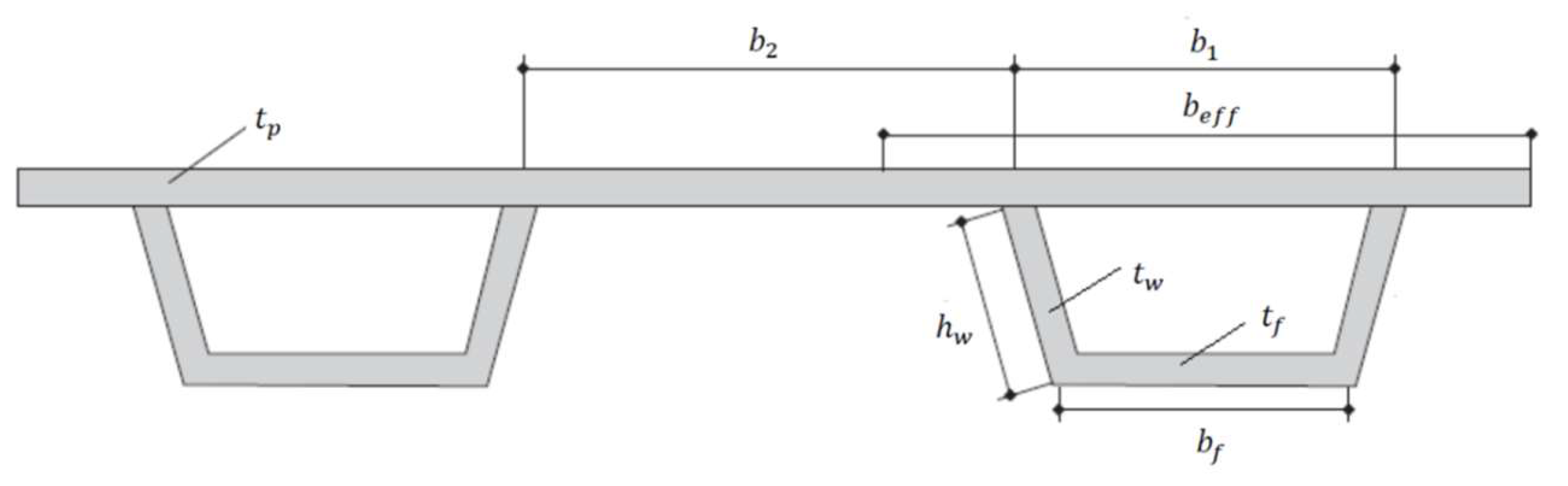
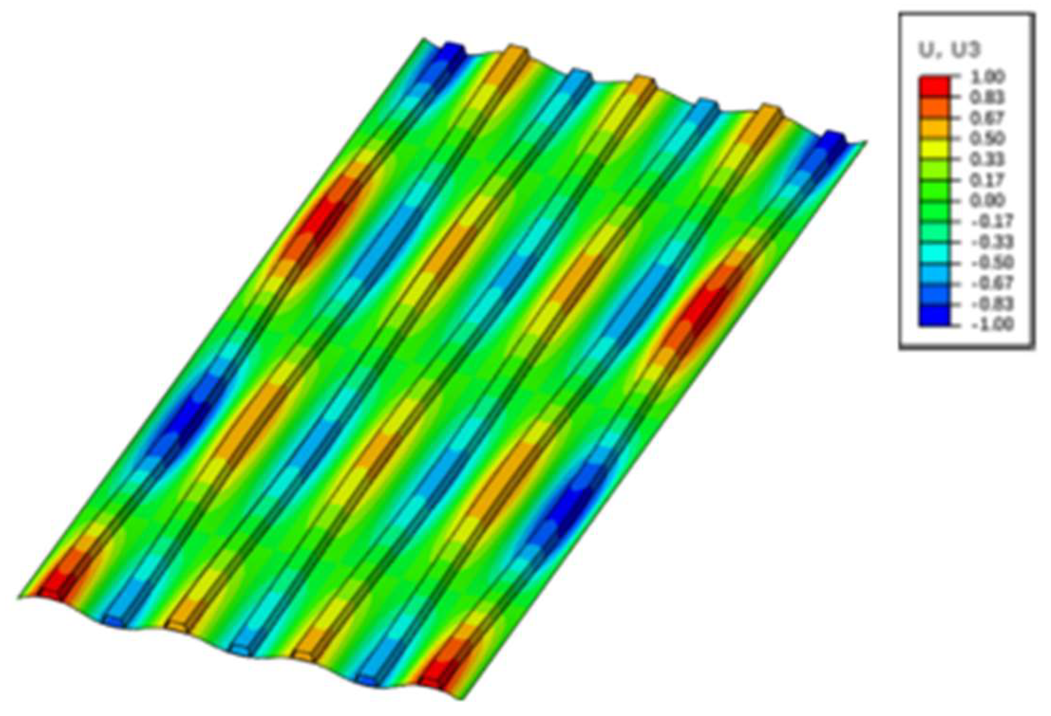
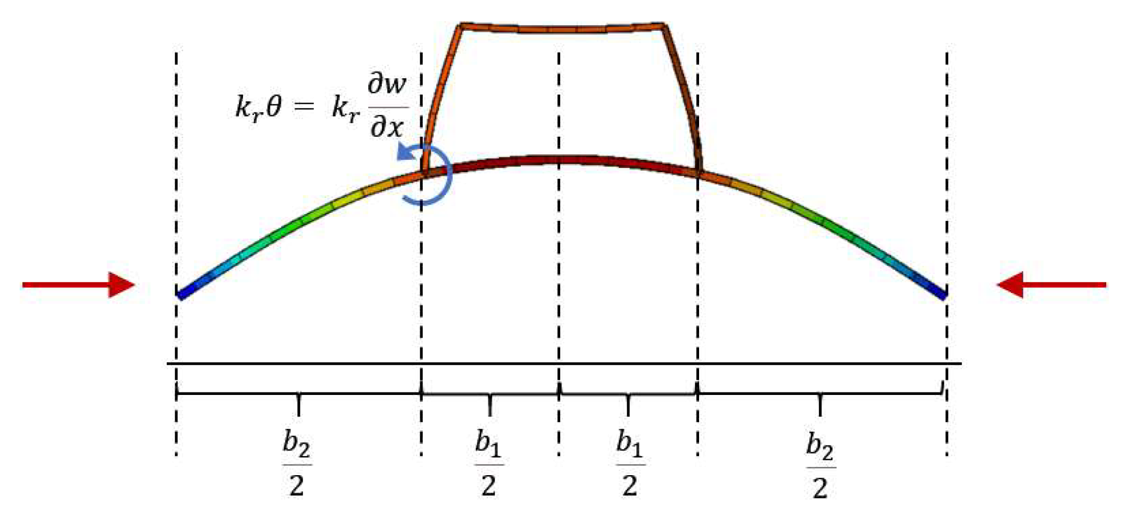
3.2. Improvements to Buckling Formulations for U-Type Stiffeners

Some hatch covers of CSR bulk carriers and of large ore carriers compliant with UR S21 are fitted with U-type stiffeners, as shown in Figure 5, where b e f f is the effective thickness of the attached plating. As an approximate method for industry application, the U-type stiffener was idealized as a Tee-bar stiffener with an equivalent bending moment of inertia.
However, advanced numerical analyses with the nonlinear finite element method show that the rule requirements for panels fitted with U-type stiffeners, including the above Tee-bar idealization, need to be improved. For this purpose, two analytical models are established to develop new buckling formulations [10].
One model proposes the GEB formulas specific to panels with U-type stiffeners. Under transverse loads, the global elastic buckling mode is typically an up-and-down pattern, as shown in Figure 6. The U-type stiffener has a stiffening effect on the transverse bending stiffness, and this increased stiffness is estimated by considering a unit width with a U-type stiffener, as illustrated in Figure 7. In the figure, θ and k r refer to the rotation angle and rotational stiffness of the U-type stiffener web, respectively.
For the unit width analysis model in Figure 7, the following deflection function is assumed.
w = A sin π b 1 + b 2 x
Considering the effect of U-type stiffener rigidity with an energy-conservative law, it gives the following equivalent transverse bending stiffness coefficient:
D 22 = E t p 3 12 1 ν 2 1.2 + 4.8 × M i n 1.0 , b 1 2 h w b 1 + b 2 × M i n 1.0 , t w t p 3
The symbols in the above formula are defined in Figure 5, and E is Young’s modulus. For the detailed process of deriving the above formulations, refer to the Technical Background for Rule Change Notice for CSR 2022 [10]. Incorporating this formula into CSR, regarding a set of typical panels from hatch covers with U-type stiffeners, the computed buckling stresses (critical transverse load) are shown in Figure 8, which shows good agreement between the formula (GEB proposal in Figure 8) and the corresponding FE results (FEM in Figure 8) [10].
For rule application, the GEB capacity is considered as one of the upper limits for buckling strength assessment considering all possible buckling failure modes. To verify the above formulas, both eigenvalue buckling analysis, as shown in Figure 9a, and NLFEA, as shown in Figure 9b, of a full hatch cover are carried out, indicating final structural failure exactly initiating from a global elastic buckling mode.
Similarly, for the local buckling mode of the elementary plate panel between two adjacent stiffeners, another strip analysis model is established and used to propose new buckling formulas to better consider the edge-constraining effect of U-type stiffeners along the longer side edges [10].

4. Development of UR S21 (Rev.6)

4.1. General Guidelines

As a general guideline, the development of UR S21 (Rev.6) is a complete revision of UR S21, which has two aspects. The first is to adopt a new buckling methodology for hatch cover analysis based on CSR. The second is to further harmonize and combine UR S21 and S21A as a single UR S21. After these two are combined, UR S21A is deleted [6].
(1) Regarding the first aspect, i.e., the improvement to the buckling requirements in UR S21, a major revision is made to Section S21.3.6 “Buckling Strength”. As shown in the comparison in Table 1, two directly related items, Section S21.3.1 “Yield Strength” and Section S21.3.2 “Stress Calculation Model”, are also improved based on the improved corresponding requirements in the latest CSR 2023.
As shown in Figure 1, the introduction of the new buckling methodology into the harmonized UR S21 has been carried out as part of the comprehensive work package of harmonizing the buckling requirements in all Relevant UR-S, including UR S11, S11A, S21, and S21A.
As specified in the technical background document of UR S35 [12], for the application of UR S35 to specific ship types or structural members requiring buckling assessment, the definitions of loading conditions, standard corrosion deductions, hull girder stresses, stress combinations, and safety factors should be given in the individual Relevant UR-S. Based on these definitions as input parameters, wherever applicable, the Relevant UR-S is linked to UR S35 for buckling assessment with respect to slenderness requirements, prescriptive buckling requirements, and buckling requirements for direct strength analysis. With this framework of general rule organization and a standardized interface of reference to the same UR S35 for buckling assessment in all Relevant UR-S, the harmonization of buckling requirements in all related IACS Resolutions is achieved.
Specifically, for the complete revision of UR S21, the definition of load model, net scantlings, stress calculation methods, and safety factors are given in S21.3.6 and are to be used as input parameters for the buckling check, while a link to UR S35 is also given, referring to the common unified slenderness requirements and the buckling assessment requirements for direct strength analysis.
(2) Regarding the second aspect, referring to the harmonization and combination of UR S21 and S21A, all the requirements in UR S21A are harmonized with the corresponding parts in S21, which are then included in UR S21 (Rev.6).

4.2. General Framework of UR S21 (Rev.6)

The general framework is to clarify in more detail the general rule organization and to define a standardized interface of reference to UR S35 for buckling assessment in all Relevant UR-S.
As shown in Figure 1, UR S35 is developed as a unified buckling toolbox applicable to all Relevant UR-S. Therefore, for the rules to be included in UR S35, a maximum set of common buckling requirements are identified and adapted from the latest CSR 2023, which has incorporated all rule improvements in Section 3 of this paper.
Based on the general guideline and categorization of all buckling-related requirements, a general framework, shown in Figure 10, is proposed, showing the categorization of related rule requirements and the application of Relevant UR-S in conjunction with UR S35 [6]. In this way, the interface of UR S35 with the Relevant UR-S is also standardized.
As illustrated in Figure 11, with a standardized interface in each revised Relevant UR-S, there is both a reference to UR S35 and also definitions of necessary parameters as input to UR S35 to perform detailed buckling formula calculations and buckling strength assessment.
After improving the buckling requirements in UR S21 and S21A based on UR S35, respectively, as shown in the comparison in Table 1, all the requirements in UR S21A are further harmonized with corresponding parts in UR S21 as far as possible, which are then included in UR S21 (Rev.6). To be equivalent with original rules, the harmonized rules should be applicable to all ship types other than CSR, consisting of strength requirements for all cargo hatch covers and coamings on exposed decks. However, just as in Part 2 of CSR, the parts of the requirements that are only applicable to certain types of ships should also be included in UR S21 (Rev.6), for which the following two groups of ships are categorized [12]:
  • Type-1 ships, including all ships except bulk carriers, self-unloading bulk carriers, ore carriers, and combination carriers, as defined in UR Z11.
  • Type-2 ships, including all bulk carriers, self-unloading bulk carriers, ore carriers, and combination carriers, as defined in UR Z11.

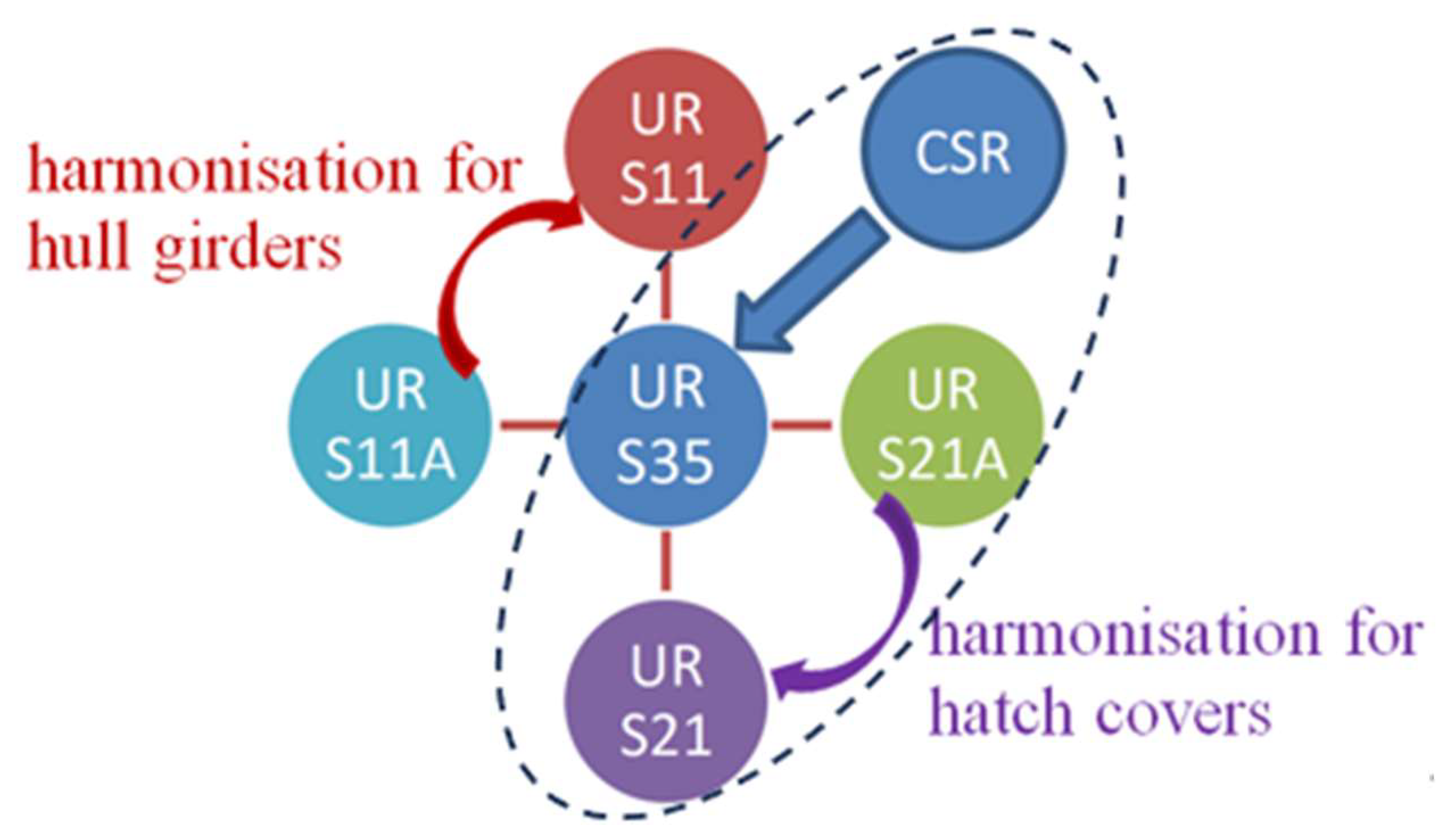
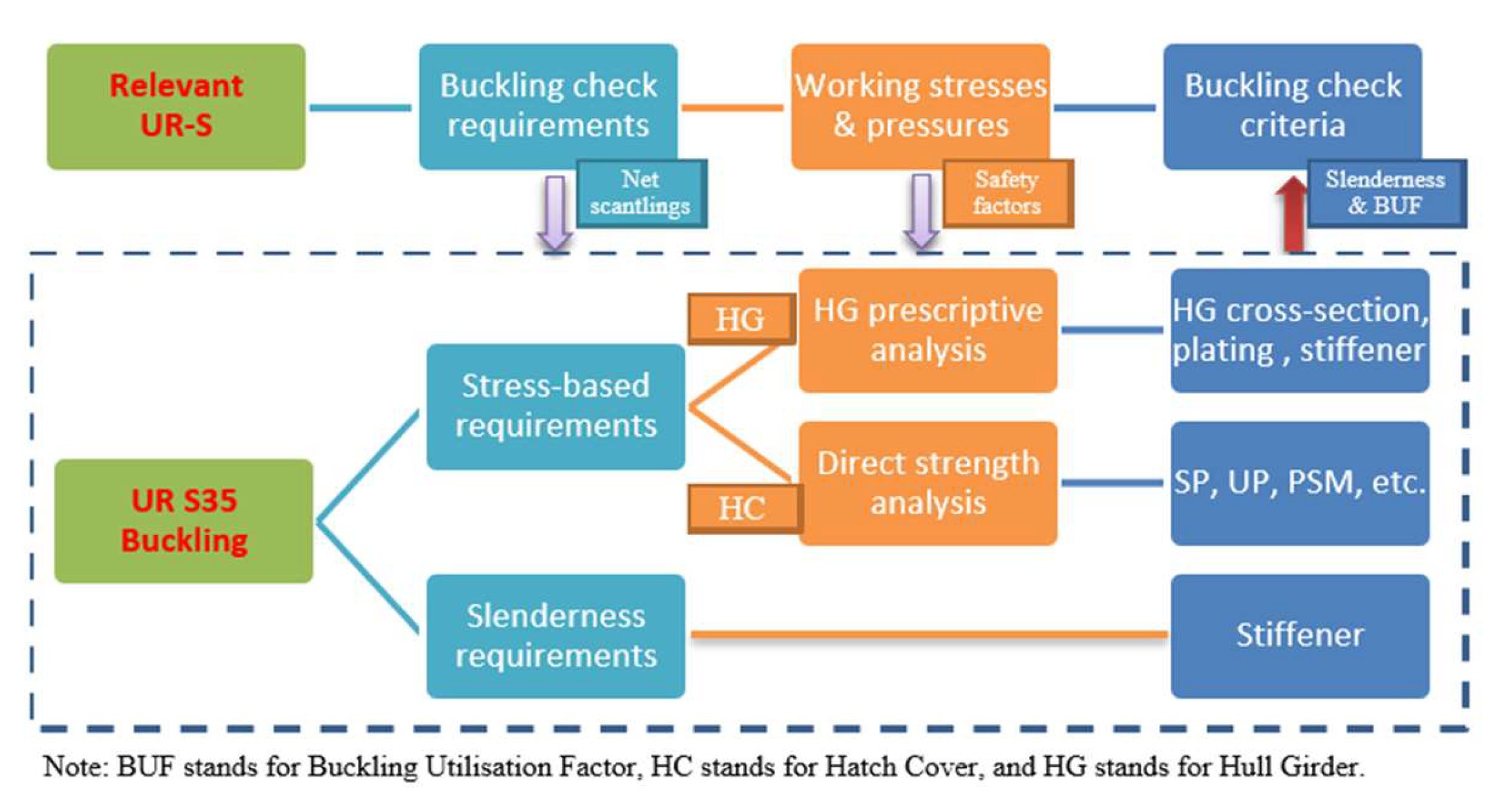
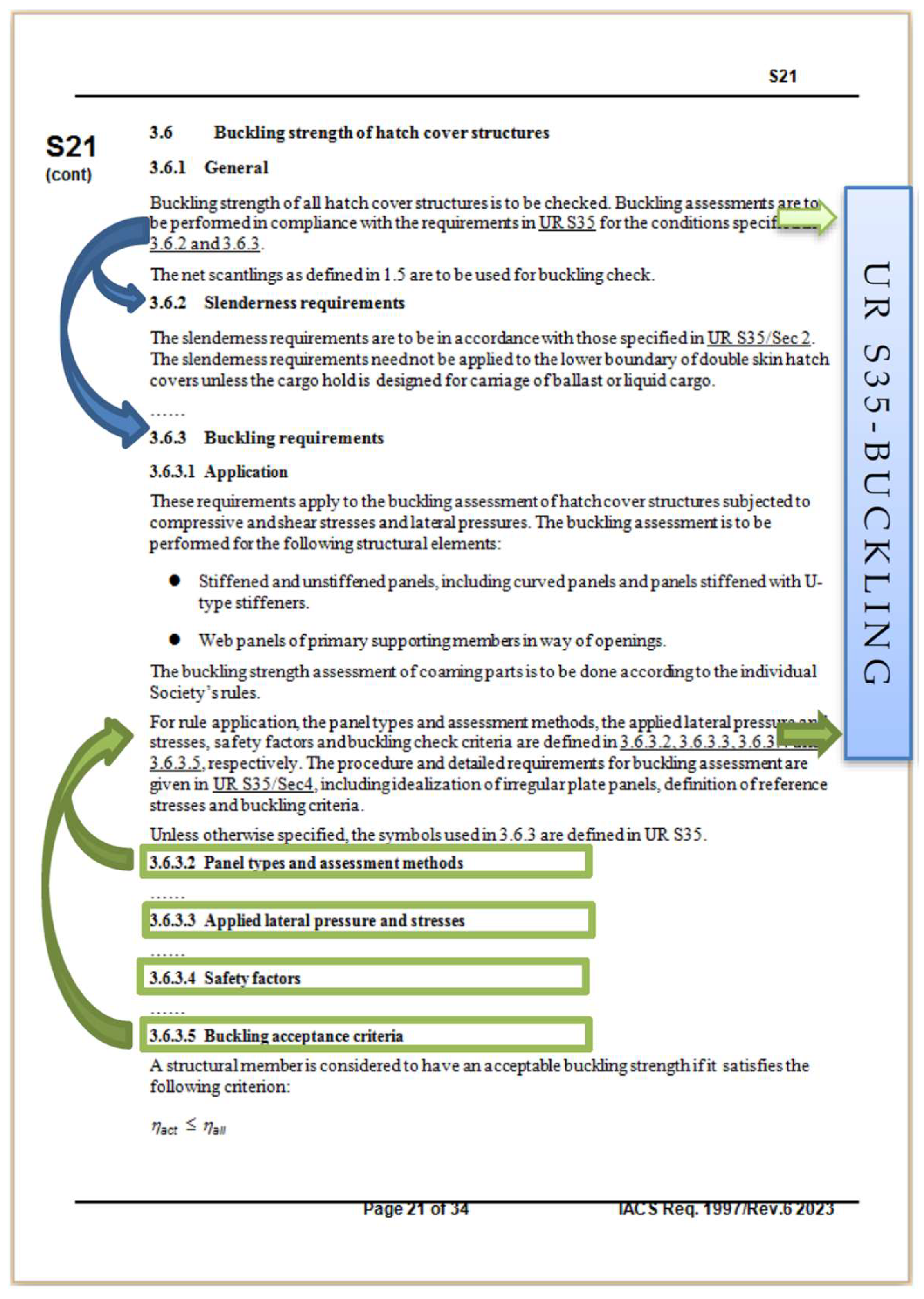
4.3. Harmonization of Buckling Requirements

Based on plenty of experience applying the CSR buckling methodology in CSR and the improvements in Section 3 of this paper, and following the general framework in Section 4.2, it is straightforward to link or apply the proposed UR S35 to UR S21.
However, besides the buckling methodology itself, there are still two directly related aspects to be harmonized, i.e., the structural analysis/stress calculation method and the buckling check criteria.
For the first aspect, regarding the structural analysis/stress calculation method for the direct strength analysis of the hatch cover, conceptually, in the IACS rules, it consists of three methods, i.e., the finite element method (FEM), the grillage analysis, and the isolated beam analysis method, as shown in Table 3.
However, limitations inherent in the grillage/isolated beam methods are deemed not appropriate for some critical cases. For example, the shear stress in the hatch cover’s plate panels is not considered accurately in the grillage/isolated beam methods, but it has been found to be a major factor leading to some serious structure collapses, especially at the hatch cover corners [10]. Therefore, only FEM is to be kept in the harmonized hatch cover rules.
For the second aspect, regarding the buckling check criteria, both safety factors and allowable buckling utilization factors are defined in IACS rules, which, in combination, are actually numerically related to obtain the appropriate safety level. In the harmonized rules, following the corresponding CSR requirements, the safety factors are all set to 1.0, and the allowable buckling utilization factors defined in Table 4 are adopted [12].
The value of the allowable buckling utilization factor η a l l = 0.8 corresponding to vertical weather design load is to comply with the ICLL requirements [7]. The additional values of η a l l = 0.9 or 0.72 for other dynamic or static loads, respectively, are introduced to account for the appropriate safety level of structures mainly subject to local lateral pressures, as was verified in CSR.

4.4. Harmonization of Other Requirements

For this harmonization, firstly, all major structural strength requirements with possible scantling impacts are compared. Specifically, the formulae related to the following aspects are compared:
  • Hatch covers’ local strength on plating and stiffeners;
  • PSM and edge girders
  • Hatch coaming plating, stiffeners, coaming stays, and securing devices.
The comparison of the above aspects, as illustrated in Table 2, shows that generally all scantling requirements in UR S21 and S21A can be harmonized, except for the following items, due to some identified reasons.
First, due to different horizontal weather design loads in UR S21A, 2.2, and UR S21.4.1, the following items need to be listed as dependent on either Type-1 or Type-2 ships:
  • S21A, 5.1: Local net plate thickness of coamings;
  • S21A, 5.2: Net scantling of stiffeners of coamings;
  • S21A, 5.3.1: Coaming stay section modulus and web thickness;
  • S21A, 7.1 Corrosion addition for hatch covers and hatch coamings.
Second, there are some requirements included in UR S21A but not in UR S21. Some of them are harmonized based on the calculation of typical designs showing no apparent scantling impact, such as the hatch cover stiffener shear area requirement in S21A, 3.3. However, based on calculations of typical designs showing an apparent scantling impact, the following requirements are only specified for Type-1 ships:
  • S21A, 3.4.2: Edge girders (skirt plate) thickness requirement;
  • S21A, 5.2: Requirement of the gross thickness of the coaming plate with sniped stiffeners;
  • S21A, 6.2.2: Hatch cover supports with tabled permissible nominal surface pressure.
In addition, there are some detailed requirements in UR S21 but not in UR S21A, which are to be specified only for Type-2 ships:
  • S21A, 5.3.1: Size of welding at the lower end of coaming stays;
  • S21A, 6.2.3: Some specific requirements on hatch cover stoppers.
With the above harmonization and classification of all requirements in UR S21 and S21A, besides the already-identified consequences caused by buckling rule improvement and some other harmonized requirements, it is considered that no apparent scantling impact is to be caused by the further harmonization in this subsection and the combination of UR S21 and S21A as a single UR S21 (Rev.6).
In addition, to deal with the identified issues in Section 2.1 regarding the definition of symbols and units, as far as possible, the symbols used in CSR 2022 are followed in the revised UR S21, which makes it easier for either rule application by industry or future further rule harmonization.

5. Numerical Verification and Consequence Assessments

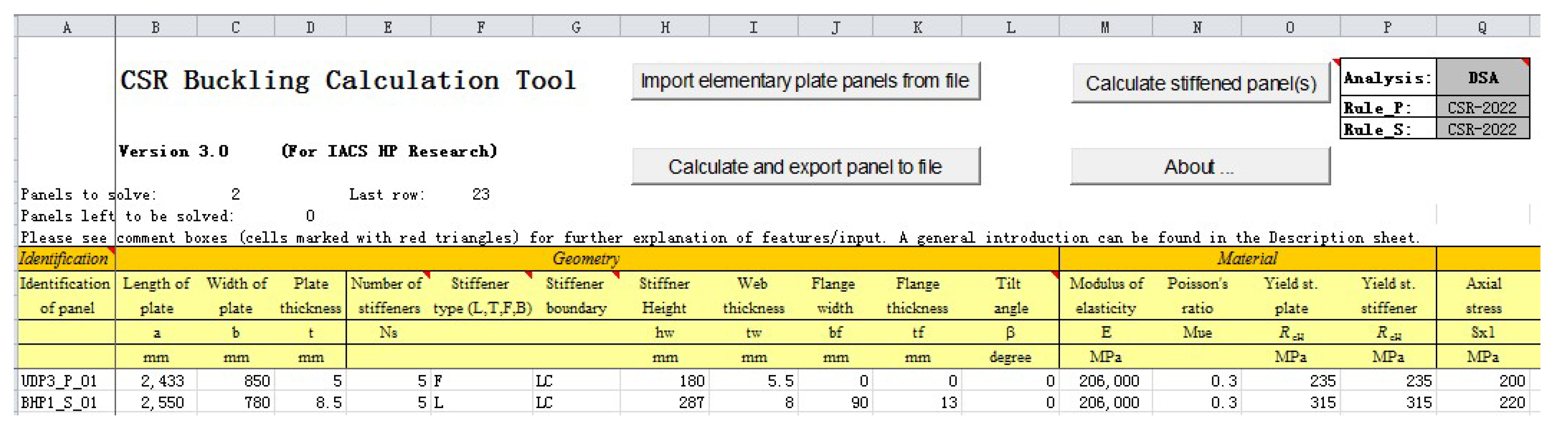
5.1. Development of Buckling Tools and Software Cross-Check

For each rule improvement required by IACS and for the convenience of industry, consequence assessment needs to be carried out to demonstrate the possible scantling impact for typical designs. However, the rules, as a complex integral system of requirements, are usually interrelated, and the effect of changing one requirement is not readily available without carrying out all related calculations based on Society software or tailored calculation tools. In addition, due to the complexity of rule software, it is necessary to carry out some cross-checks among societies to ensure a uniform understanding and implementation of each rule requirement and also to obtain correct results with minimum or no software bugs.
Therefore, within a dedicated IACS project team, the calculation tools for UR S21 and CSR are developed and used to cross-check the software of different classification societies. The calculation spreadsheet for the CSR buckling rules is shown in Figure 12, with some required panel data as input and with all buckling results, including key intermediate values. In this way, the correctness of the Society software used for consequence assessment can generally be ensured.

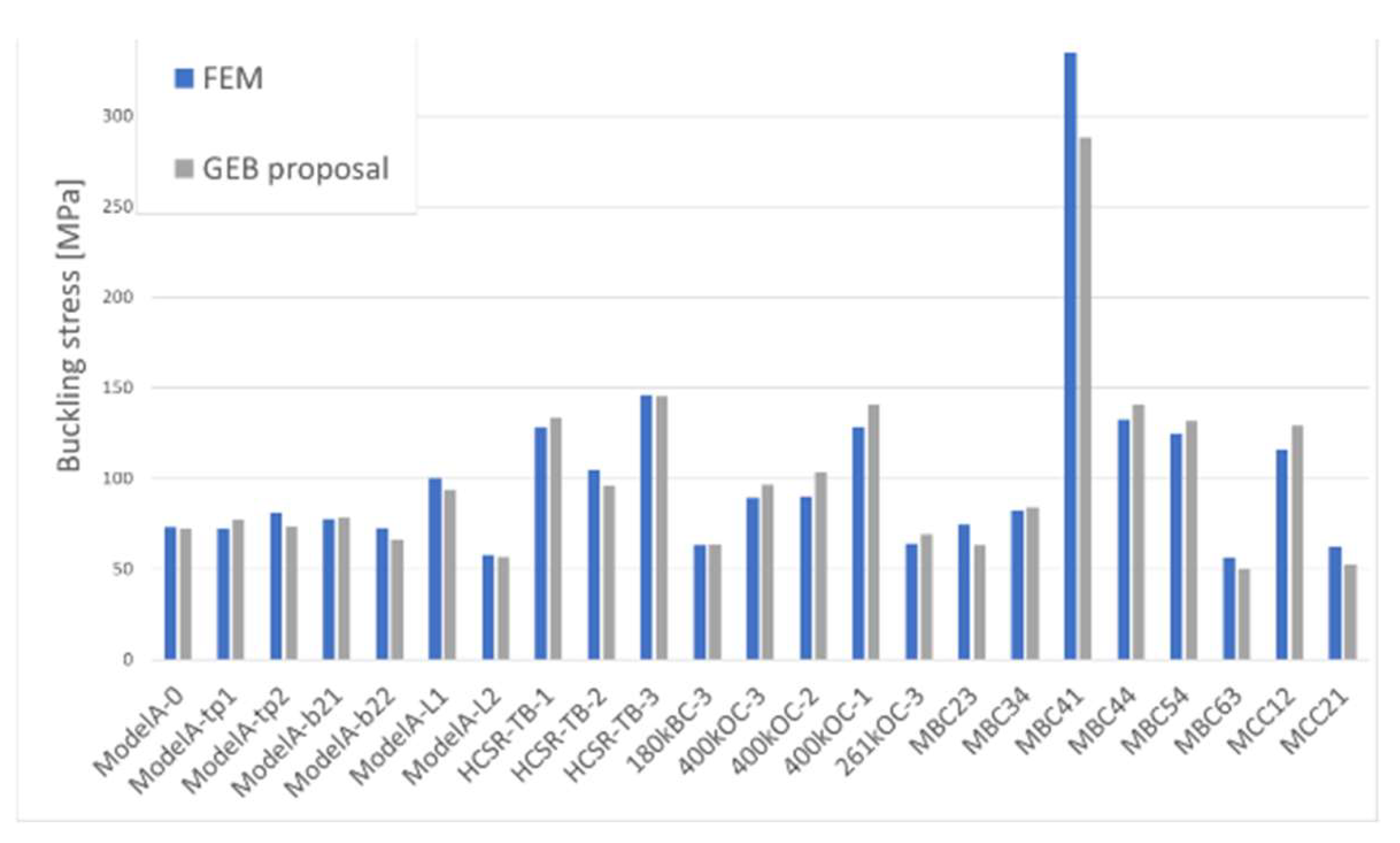
5.2. Numerical Calculation of Typical Stiffened Panels

To be representative of a variety of ship designs, a set of stiffened panels from typical hatch covers is collected from classification societies and major hatch cover makers. Following the standard IACS buckling and the ultimate strength-analysis procedure [11], extensive multistep nonlinear finite element analyses are carried out to calculate all the representative panels within the IACS project team, which are then compared with the corresponding results of the spreadsheet in Figure 12.
As an illustration, a comparison of a set of hatch cover panels fitted with U-type stiffeners is shown in Figure 13, which shows that with the new buckling rules in UR S21 (Rev.6), generally good agreement with FEM results is achieved.

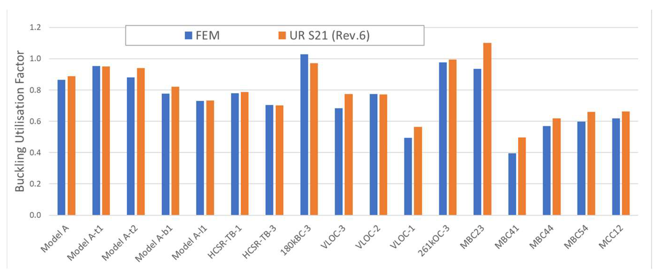
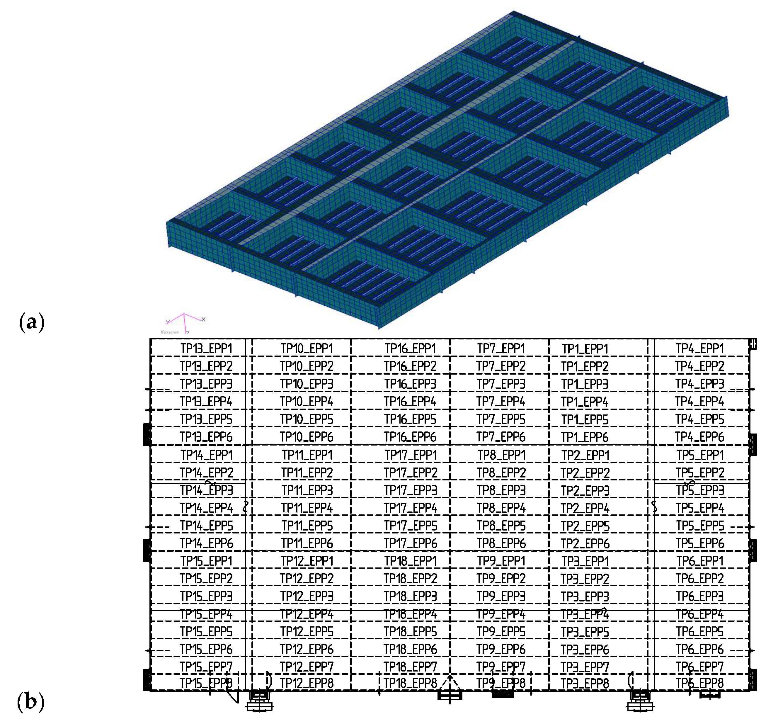
5.3. Numerical Calculation of Typical Hatch Covers

For consequence assessment, numerical calculations are carried out to calculate some representative full hatch cover models using the harmonized UR S21 (Rev.6) and the original rules. All calculations are performed using Society software after cross checking. As shown in Figure 14, it is the No. 1 hatch cover model of a 325kDWT bulk carrier. From detailed comparisons of the buckling assessment results between the revised UR S21 (Rev.6) and the previous version (Rev.5), the following conclusions can be ontained.
(1) For plate buckling check, generally, there is some decrease in buckling-utilization factors except for some panels subject to combined axial and big shear stresses, such as EPPs with the prefixes TP4 and TP5 in Figure 14. However, there is almost no scantling impact on the top plating. The findings demonstrate that the new plate buckling requirements in the revised S21 are more reasonable, while the previous version, which checks panel buckling based on a single stress component, might give non-conservative results for panels that are actually subject to complex combined stresses.
(2) For the stiffener buckling check, with the revised UR S21, it shows increased buckling utilization factors for most stiffeners, especially those located in the central region with the prefix TP7~TP9. This agrees with the findings related to Figure 3 in Section 2.2 and the GEB rule improvement in Section 3.1 regarding panels subject to dominant transverse stresses. Therefore, the hatch covers designed following the previous version of UR S21 (Rev.5) need to be strengthened or redesigned in the identified local area.
(3) Based on analyses of more hatch covers and design modifications to meet the new rules, the computed results indicate that the revised UR S21 may cause a 3% total weight increase for relatively large hatch covers. However, for some previously designed hatch covers, based on the currently more accurate buckling assessment methods, proper structural optimization may lead to more reasonable hatch cover designs even with some weight decrease [12]. Therefore, it can be concluded that the revised UR S21 (Rev.6) is generally acceptable from both the theoretical and the practical points of view.
In addition, for consequence assessment regarding those rules other than buckling, as indicated in Section 4.4, it is considered that no apparent scantling impact should be observed. Specifically, for the hatch cover stiffener shear area requirement in UR S21A, 3.3, for example, it is a requirement that was originally included in UR S21A but not in UR S21; after harmonization, it applies to both Type-1 and Type-2 ships in UR S21 Rev.6. For verification, numerical calculations are carried out regarding typical hatch cover stiffeners, which are designed following original UR S21 without considering the net shear area requirement.
In Table 5, two stiffeners from the hatch covers with different lengths   l are calculated and compared, which shows that the net section modulus requirement, W W r e q , is always a factor that governs far more than the net shear area requirement, A s h A r e q . So no scantling impact is expected to be caused by this rule harmonization. In the table, t , t k , and t n e t refer to gross thickness, corrosion, and net thickness, respectively; s and l refer to stiffener spacing and length, respectively; P L refers to the load on hatch covers due to distributed cargo loads; R e H refers to material yield stress; and σ a and τ a refer to allowable axial and shear stresses, respectively.

6. Concluding Summary

This paper presents the work carried out by IACS developing the unified strength requirements of hatch covers—a complete revision of UR S21 (Rev.6). With UR S35 being developed as a unified buckling toolbox, the unified strength requirements for hatch covers—UR S21 (rev.6, complete revision)—are developed with a standardized interface with reference to UR S35 for buckling assessment.
In addition, based on the development of this rule, which is very important for hatch cover makers around the world and also important to the ship industry, the following results and conclusions are obtained:
  • For historical reasons, different approaches and rule formulas dealing with the same strength requirement have been used among IACS rules, including strength rules for hatch covers. This brings about some inconsistencies in the design of similar structures on different types of ships, and related rules need to be continuously improved and harmonized.
  • Related IACS rules are reviewed and compared with respect to applicable ship types, strength analysis methods, applied loads, yield strength, buckling strength, corrosion and net scantling models, hatch coaming strength and closing arrangements, etc. This shows that buckling rules are the most critical part of developing the unified strength requirements for hatch covers. Additionally, for those rules other than buckling in UR S21 (rev.6), the numerical calculation of typical structures designed following the original UR S21 shows no apparent scantling impact.
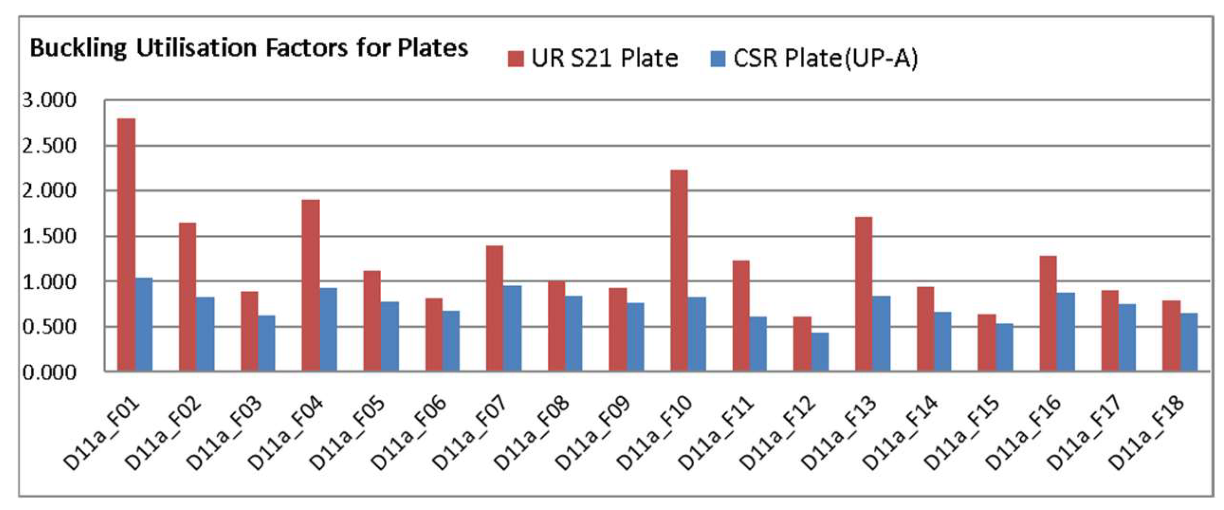
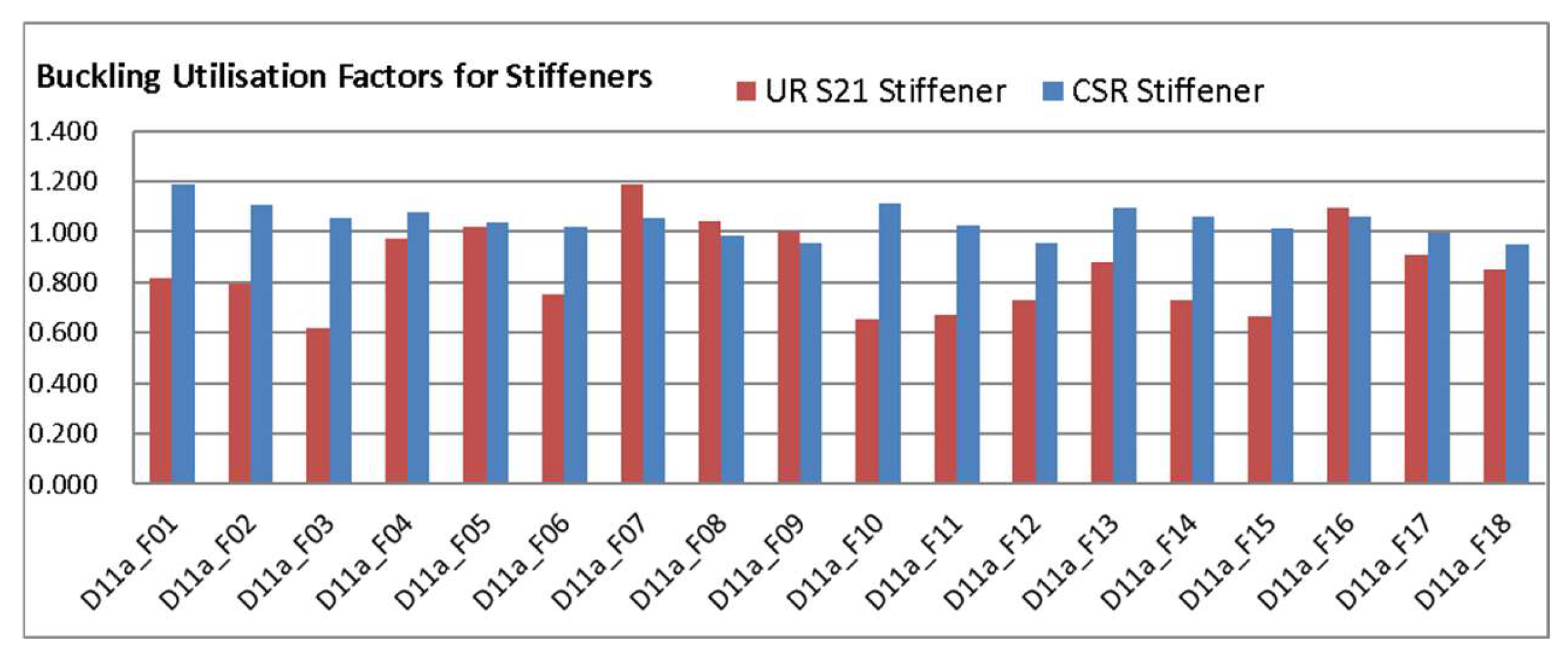
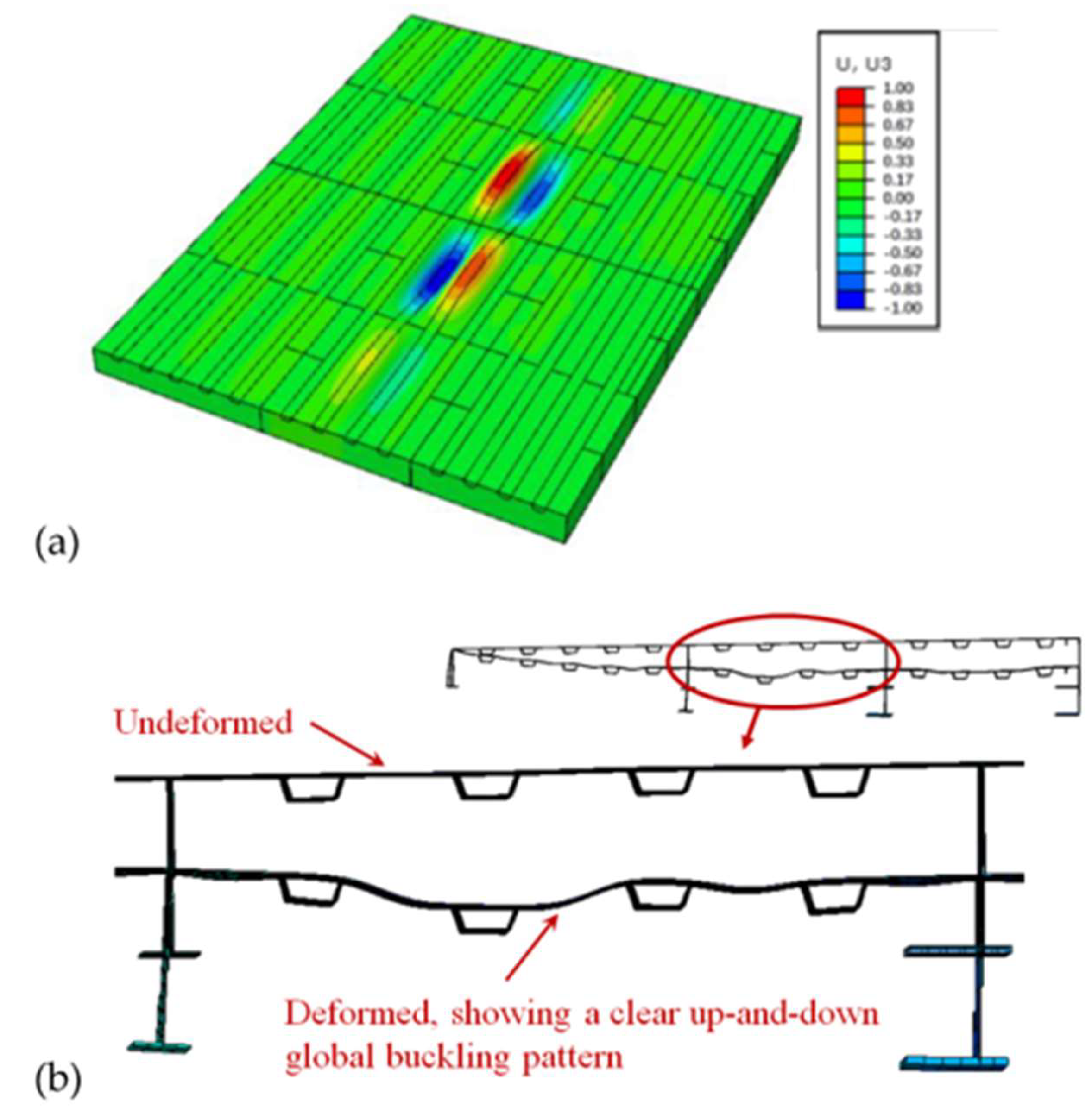
  • The numerical calculations of a set of typical stiffened panels are carried out to investigate the possible consequences caused purely by using different buckling formulas. For plate buckling, the original UR S21 is more conservative than CSR, and CSR is more conservative than UR S21, especially for very slender panels, which are usually governed by the global elastic buckling mode.
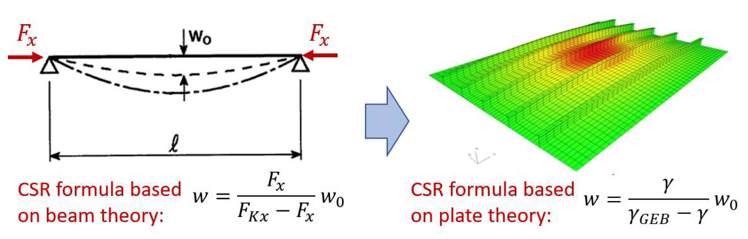
  • For rule improvements regarding the global elastic buckling mode for stiffened panels subject to combined loads, the torsional buckling of high-web stiffeners, the buckling of plate panels fitted with sniped stiffeners, the buckling of very slender panels, etc., generally good agreements with FEM results are achieved.
  • To improve the buckling assessment of hatch covers fitted with U-type stiffeners, some new buckling formulas are proposed based on both theoretical analysis and comprehensive numerical calculations, showing good agreement with FEM results.
  • Calculation tools are developed and used to cross-check the software of different classification societies. Regarding a set of stiffened panels from typical hatch covers that are representative of a variety of ship designs, the buckling rule formulas in UR S21 (Rev.6) are verified by comparing them with extensive FEM results calculated following the standard IACS buckling and ultimate strength-analysis procedure.
  • Calculations regarding a set of hatch cover panels fitted with U-type stiffeners show that with the new buckling rules in UR S21 (Rev.6), generally good agreement with FEM results is achieved.
  • Numerical calculations of typical stiffened panels and full hatch covers are carried out for rule verification and consequence assessment, demonstrating that more rational hatch cover designs can be achieved based on the developed unified strength requirements for hatch covers—UR S21 (rev.6).

Author Contributions

Conceptualization, Y.L., L.B., K.I. and A.B.; Methodology, Y.L., L.B., K.I. and P.A.S.; Software, Y.L., L.B. and K.I.; Validation, Y.L., L.B., K.I. and A.B.; Formal analysis, Y.L., L.B. and K.I.; Investigation, A.B.; Writing—original draft, Y.L.; Writing–review & editing, L.B., K.I., A.B. and P.A.S.; Supervision, Y.L. and Å.B.; Project administration, Y.L. and Å.B.; Funding acquisition, Y.L. and Å.B. All authors have read and agreed to the published version of the manuscript.

Funding

International Association of Classification Societies, PT PH43.

Institutional Review Board Statement

Not applicable.

Informed Consent Statement

Not applicable.

Data Availability Statement

Restrictions apply to the availability of these data. Data was obtained from IACS, and are available from the authors with the permission of IACS.

Conflicts of Interest

The authors declare no conflict of interest.

Glossary

BUFBuckling utilization factor.
Corr.Corrigenda, collection of editorial corrections for a rule version.
CSRCommon Structural Rules for bulk carriers and oil tankers issued by IACS with periodical revisions. For example, CSR 2022 refers to the version released on 1 January 2022 to supersede previous versions.
CSR-OTCommon Structural Rules for oil tankers, which have been superseded by CSR.
EPPElementary plate panel, the smallest plate element surrounded by structural members, such as stiffeners, PSM, and bulkheads.
FEAFinite element analysis.
FEM/FEFinite element (method).
GEBGlobal elastic buckling.
GrillageGrillage beam analysis method that represents the hatch cover as an equivalent grillage of beams.
HCHatch cover.
HGHull girder.
IACSInternational Association of Classification Societies.
ICLLInternational Convention on Load Lines administered by the International Maritime Organization.
Isolated beamIsolated beam analysis method that represents the hatch cover as an equivalent isolated beam.
NLFEANonlinear finite element analysis.
PSMPrimary support members, members of the beam, girder, or stringer type, which provides the overall structural integrity of the hull envelope and tank boundaries.
Rev.Revision of a rule version.
Type-1 shipsAll ships except bulk carriers, self-unloading bulk carriers, ore carriers, and combination carriers, as defined in UR Z11.
Type-2 shipsAll bulk carriers, self-unloading bulk carriers, ore carriers, and combination carriers, as defined in UR Z11.
TPxTop plating of a hatch cover with numbering x.
URUnified Requirements, minimum technical requirements adopted by IACS, which, subject to ratification by the governing body of each IACS Member, are to be incorporated in their rules and practices.
UR S11Unified Requirements concerning Strength of Ships—Longitudinal Strength Standard.
UR S11AUnified Requirements concerning Strength of Ships—Longitudinal Strength Standard for Container Ships.
UR S21Unified Requirements concerning Strength of Ships—Evaluation of Scantlings of Hatch Covers and Hatch Coamings and Closing Arrangements of Cargo Holds of Ships. Before Rev.6, it is only applicable to non-CSR Bulk Carriers, Ore Carriers, and Combination Carriers.
UR S21ASame meaning as UR S21, but applies to all ships except bulk carriers, self-unloading bulk carriers, ore carriers, and combination carriers.
UR S35Unified Requirements concerning Strength of Ships—Buckling Strength Assessment of Ship Structural Elements.
UR Z11Unified Requirements concerning Survey and Certification—Mandatory Ship Type and Enhanced Survey Programme (ESP) Notations.

References

  1. International Association of Classification Societies. Common Structural Rules for Bulk Carriers and Oil Tankers (CSR); Electronic Publication: London, UK, 2023; Part 1 Chapter 8, Part 2 Chapter 1. [Google Scholar]
  2. International Association of Classification Societies. Requirements Concerning Strength of Ships—(UR S11, S11A, S21, S21A); Electronic Publication: London, UK, 2022. [Google Scholar]
  3. International Association of Classification Societies. Requirements Concerning Survey and Certification—(UR Z11); Electronic Publication: London, UK, 2022. [Google Scholar]
  4. Horn, G.E.; Toshiro, A.; Baumans, P.; Bøe, Å.; Hasan, O. IACS summary of the IMO GBS and the Harmonised Common Structural Rules. In Proceedings of the TSCF 2013 Shipbuilders Meeting, Shanghai, China, 23–24 October 2013. [Google Scholar]
  5. Brubak, L.; Lv, Y.N.; Ishibashi, K.; Bollero, A.; Bøe, Å. Rule formulation updates on buckling strength requirements in Common Structural Rules. In Proceedings of the 9th International Conference on Marine Structures (MARSTRUCT 2023), Gothenburg, Sweden, 3–5 April 2023; pp. 339–346. [Google Scholar]
  6. International Association of Classification Societies. Requirements Concerning Strength of Ships—(UR S21, S21A, S35); Electronic Publication: London, UK, 2023. [Google Scholar]
  7. International Maritime Organization. International Convention on Load Lines (ICLL), 1966 as Amended by the 1988 Protocol, as Amended in 2003; Electronic Publication: London, UK, 2015. [Google Scholar]
  8. International Association of Classification Societies. Common Structural Rules for Bulk Carriers and Oil Tankers (CSR 2021–2022); Electronic Publication: London, UK, 2022. [Google Scholar]
  9. International Association of Classification Societies. Common Structural Rules for Double Hull Oil Tankers (CSR-OT); Electronic Publication: London, UK, 2012; Section 10, Appendix D. [Google Scholar]
  10. International Association of Classification Societies. Technical Background for Rule Change Notice for CSR 2020–2023; Electronic Publication: London, UK, 2023; Part 1 Chapter 8, Part 2 Chapter 1. [Google Scholar]
  11. International Association of Classification Societies. TB Report for CSR BC & OT: Validation of Non-linear Buckling Procedure; Electronic Publication: London, UK, 2015. [Google Scholar]
  12. International Association of Classification Societies. Technical Background for Requirements Concerning Strength of Ships—(UR S21, S21A, S35); Electronic Publication: London, UK, 2023. [Google Scholar]
Figure 1. Roadmap for related rule development in IACS, with UR S35 being developed as a unified buckling toolbox.
Jmse 11 01558 g001
Figure 2. Comparison of plate-buckling utilization factors calculated using buckling formulas in UR S21 and CSR for some representative panels subject to axial loads.
Jmse 11 01558 g002
Figure 3. Comparison of stiffener-buckling utilization factors calculated using buckling formulas in UR S21 and CSR for some representative panels subject to axial loads.
Jmse 11 01558 g003
Figure 4. The displacement magnifier formula using beam theory is to be replaced by that based on orthotropic plate theory.
Jmse 11 01558 g004
Figure 5. Cross-section of a hatch cover panel fitted with U-type stiffeners with scantling definition.
Jmse 11 01558 g005
Figure 6. Global elastic buckling mode of a stiffened panel fitted with U-type stiffeners [10].
Jmse 11 01558 g006
Figure 7. A unit width model for global elastic buckling capacity analysis.
Jmse 11 01558 g007
Figure 8. Comparison of GEB capacities calculated with the rule and FEM for stiffened panels fitted with U-type stiffeners and subject to transverse loads.
Jmse 11 01558 g008
Figure 9. A full-hatch-cover FE model showing GEB mode. (a) Eigenvalue buckling analysis, (b) deformation with NLFEA at final structural failure.
Jmse 11 01558 g009
Figure 10. The general framework to show relations between UR S35 and the Relevant UR-S.
Jmse 11 01558 g010
Figure 11. Illustration of the standardized interface between UR S35 and the Relevant UR-S.
Jmse 11 01558 g011
Figure 12. A spreadsheet developed with Excel-VBA for CSR buckling calculation and cross checking.
Jmse 11 01558 g012
Figure 13. Comparison of buckling utilization factors calculated with FEM and the harmonized UR S21 for stiffened panels fitted with U-type stiffeners and subject to combined loads.
Jmse 11 01558 g013
Figure 14. The No. 1 hatch cover model of a 325kDWT bulk carrier. (a) Finite element model, (b) a model showing elementary plate panel (EPP) definitions used for buckling assessment.
Jmse 11 01558 g014
Table 2. Comparison of local strength requirements for plates/stiffeners in different rules [2,8].
UR S21 Rev.5UR S21A Rev.1CSR 2022
Plate: minimum thickness
t = F p · 15.8 s p 0.95 σ F t = F p · 15.8 s p 0.95 σ F t = 0.0158 F p b F s P s + F w P w 0.95 R e H
Stiffener: minimum section modulus and shear area
Z = 1000 l 2 s p 12 σ a Z = 104 p s l 2 σ F (wave load)
or Z = 93 p s l 2 σ F (cargo load)
Z = F s P s + F w P w s l s 2 f b c σ a
A s = 10.8 p s l σ F (wave load)
or A s = 9.6 p s l σ F (cargo load)
A s h r = 5 F s P s + F w P w s l s σ a 10 3
Table 3. Hatch cover analysis/stress calculation methods in different rules [2,8].
MethodsUR S21 Rev.5UR S21A Rev.1CSR 2021CSR 2022
FEM
Grillage
Isolated beam
Table 4. Allowable buckling utilization factors adopted in the harmonized UR S21.
Structural ComponentSubject to η a l l , Allowable Buckling
Utilization Factor
Plates and stiffeners
Web of PSM
External pressure, as defined in UR S21, 2.10.80
Other loads (cargo loads, etc.)0.90 for static + dynamic load case
0.72 for static load case
Table 5. Stiffener section modulus and shear area results calculated with UR S21 (Rev.6).
StiffenersttktnetWAsh l PLReHaaWreqAreqY/N
mmmmmmmcm3cm2mkN/m2N/mm2N/mm2N/mm2cm3cm2
HP160x70.5581.56.594.89.62.568.5355284.0163.368.42.87Y
HP160x70.5 81.56.594.89.61.668.5355284.0163.327.11.81Y
Disclaimer/Publisher’s Note: The statements, opinions and data contained in all publications are solely those of the individual author(s) and contributor(s) and not of MDPI and/or the editor(s). MDPI and/or the editor(s) disclaim responsibility for any injury to people or property resulting from any ideas, methods, instructions or products referred to in the content.

