Article

Analysis of the Steady-Stream Active Flow Control for the Blended-Winged-Body Underwater Glider

School of Marine Science and Technology, Northwestern Polytechnical University, Xi’an 710072, China
*
Author to whom correspondence should be addressed.
J. Mar. Sci. Eng. 2023, 11(7), 1344; https://doi.org/10.3390/jmse11071344
Submission received: 18 May 2023 / Revised: 7 June 2023 / Accepted: 24 June 2023 / Published: 30 June 2023
(This article belongs to the Special Issue Autonomous Marine Vehicle Operations)

Abstract

:
The BWB-UG is a glider with a smooth and integrated fuselage and wing. Its lift-to-drag properties are some of the most significant factors affecting its performance. In order to improve its hydrodynamic characteristics, the method of steady-stream active flow control (SS-AFC) is proposed. The computational fluid dynamics method is used to numerically investigate the SS-AFC of the BWB-UG. The mechanism of the SS-AFC effect on the lift-to-drag characteristics is revealed from the flow field aspect. The flow field of the BWB-UG before and after installing the SS-AFC was simulated using FLUENT. The results show that the SS-AFC can effectively optimise the hydrodynamic characteristics of the BWB-UG and can optimise the structure of the flow field around the BWB-UG. The steady-suction AFC can increase the lift-to-drag ratio of the BWB-UG by up to 45.01 % . With the steady-jet AFC, the lift-to-drag ratio of the BWB-UG can be increased by as much as 93.17 % .

1. Introduction

The Blended-Wing-Body Underwater Glider (BWB-UG) is a tailless underwater vehicle with a full-wing configuration. It can dramatically improve the lift-to-drag ratio by increasing the area of the airfoil and providing internal space that overcomes many of the shortcomings of the traditional UG. Since American oceanographer Stommel first proposed the concept of the UG in 1989, researchers in many countries have gradually researched related technologies of the UG. The United States Naval Research Laboratory began to develop Liberdade-class large-scale BWB-UG in 2003, mainly including XRay, XRay2, and ZRay [1]. Researchers conducted a sea trial of the XRay in California. The horizontal velocity of the XRay was about, and the lift-to-drag ratio was 17. Northwestern Polytechnical University has also conducted relevant research on the BWB-UG. Du established the flow field calculation model for the BWB-UG, carried out the hydrodynamic simulation, established the 6-DOF dynamic model, and analysed the glide motion performance [2,3,4]. Li used free-form deformation to optimise the framework of geometric parameterization. An optimised BWB-UG was considered as the initial shape and four shape optimisation cases were performed for different design purposes using the proposed framework [5]. Sun carried out a shape optimisation design of the BWB-UG based on a global optimisation method with a maximum lift-to-drag ratio and maximum range as optimisation objectives [6,7,8]. However, existing studies show an irreconcilable contradiction between the optimisation of hydrodynamic performance and the maximization of piggyback space in the shape optimisation design process. At the same time, further improvement of the lift-to-drag ratio of the BWB-UG is limited by the occurrence of flow separation. In summary, the critical issue for further development in the field of overall BWB-UG design is whether a method can be found to optimise the hydrodynamic characteristics of the BWB-UG without modification of its shape.
Active flow control (AFC) is an emerging drag reduction technology to control the local flow field of the object by actively inputting appropriate disturbances to the local flow field of the object. AFC can improve the whole-field fluid structure by inputting or releasing energy at the critical point. At the same time, because of its initiative, this technology can effectively carry out accurate phase control in complex dynamic systems. The control method of steady-jet AFC is simple, and the device is easy to realize. GANESH N et al. used the CFD method to numerically study the flow field structure of NACA63 (4) -021 wing with steady-suction AFC. The results show that the aerodynamic performance can be improved by 28 % by equipping suction at 0.3 times the chord length from the wing’s leading edge [9]. Fatahian et al. conducted numerical studies on the steady-suction AFC of the NACA0012 flap. The results show that the steady-suction perpendicular to the airfoil surface can effectively improve the aerodynamic performance of the airfoil [10]. AFC technology was widely used in wind turbine lift drag reduction [11,12], ground vehicle energy-saving drag reduction [13,14,15], aircraft airfoil aerodynamic performance improvement [16,17,18,19], and other fields. Overall, AFC technology has broad application prospects in many fields. It has shown considerable potential and is likely to become a future breakthrough technology in fluid mechanics. The AFC has a good improvement effect on the hydrodynamic performance, and the structure is simple. Du et al. achieved excellent hydrodynamic optimisation results by applying the electromagnetic AFC technique to the overall design of the BWB-UG [20]. The AFC has reasonable practicability for the BWB-UG. However, from the current public research results, there are relatively few theoretical and experimental results on the AFC of the BWB-UG. The research on SS-AFC of the BWB-UG is still in the preliminary exploration stage. Therefore, studying the SS-AFC of the BWB-UG is of great theoretical significance and application value.
In this paper, the effect of the SS-AFC on the BWB-UG is analysed using the computational fluid dynamics method. Firstly, an accurate and effective numerical computational model is established. Secondly, the disturbance phenomenon of the BWB-UG equipped with the steady-jet AFC and the steady-suction AFC is numerically calculated by analysing the flow field structure characteristics and hydrodynamic trend characteristics of the BWB-UG before and after being fitted with the AFC. The mechanism of the influence of the SS-AFC on the BWB-UG is obtained.

2. Materials and Methods

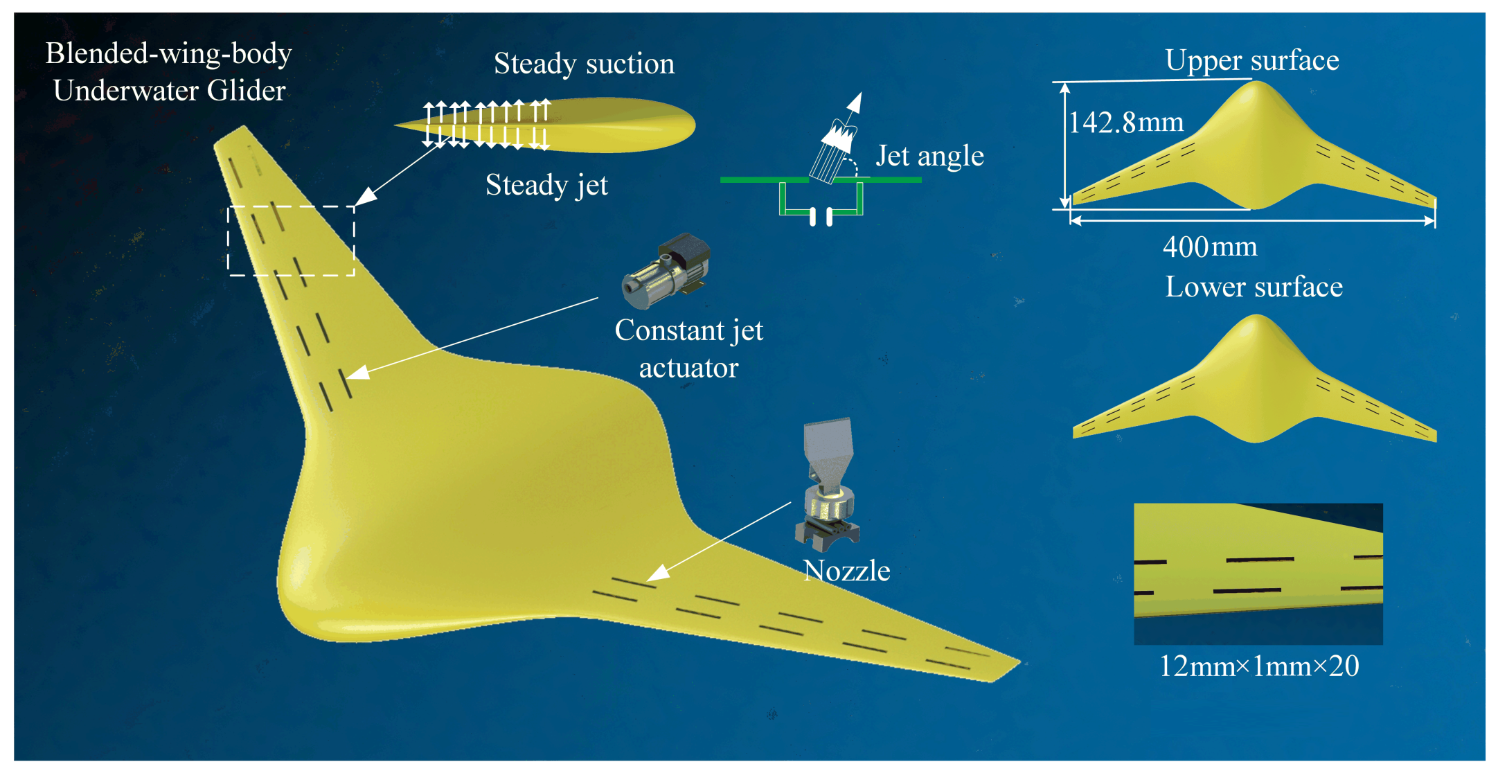
2.1. Geometric Model and Reference Definition

The SS-AFC technology is considered equipped for the BWB-UG, as shown in Figure 1. The AFC system of the BWB-UG mainly includes nozzles, a small pump, and a simple pipeline. Since the AFC has a good improvement effect on the hydrodynamic performance of the underwater glider and its structure is simple, the AFC has reasonable practicability for the underwater glider. There are 20 nozzles on the BWB-UG. The jet or suction flow rate is V s t r e a m and its direction angle is θ s t r e a m . The specific design parameters of the model are shown in Table 1. The hydrodynamic characteristics of the BWB-UG at attack angles of 0 ∼12 are calculated. The hydrodynamic characteristics before and after the equipment of the AFC are compared.
The wet surface area S h is used as the characteristic area to define the lift coefficient C l , the drag coefficient C d , and the lift-to-drag ratio R of the BWB-UG.
C l = 2 F L ρ v 2 S h C d = 2 F D ρ v 2 S h R = C l C d
where F L is the lift force; F D is the drag force; v is the flow velocity at infinity; and ρ is the density of sea water. Define the dimensionless expressions of velocity and pressure.
C p = 2 P P 0 ρ U 2
C v = V p o i n t V s t r e a m
The Q-criterion is a fundamental law in fluid mechanics to characterize the change in flow length of a fluid after deflection.
Q = 0.5 × ( d d x ( u ) 2 d d y ( v ) 2 d d z ( w ) 2 2 × d d z ( u ) × d d x ( w ) 2 × d d z ( v ) × d d y ( w ) 2 × d d y ( u ) × d d x ( v ) )

2.2. Flow Field Calculation Model

The 3-D incompressible model is selected for the relevant research. The control equation is:
( ρ u ) x + ( ρ v ) y + ( ρ w ) z = 0
ρ u ¯ u ¯ x + v ¯ u ¯ y + w ¯ u ¯ z = μ 2 u ¯ x 2 + 2 u ¯ y 2 + 2 u ¯ z 2 + ρ u u ¯ x + ρ u v ¯ y + ρ u w ¯ z p x + S f x
ρ u ¯ v ¯ x + v ¯ v ¯ y + w ¯ v ¯ z = μ 2 v ¯ x 2 + 2 v ¯ y 2 + 2 v ¯ z 2 + ρ v u ¯ x + ρ v v ¯ y + ρ v w ¯ z p y + S f y
ρ u ¯ w ¯ x + v ¯ w ¯ y + w ¯ w ¯ z = μ 2 w ¯ x 2 + 2 w ¯ y 2 + 2 w ¯ z 2 + ρ w u ¯ x + ρ w v ¯ y + ρ w w ¯ z p z + S f z
where p is fluid pressure; μ is the dynamic viscosity coefficient of fluid; u ¯ , v ¯ , w ¯ are the time-averaged velocity components of the fluid in x , y , z directions; u , v , w are the pulsating velocity components of the fluid in x , y , z directions; S f x , S f y , S f z are generalized source terms of momentum equations in x , y , z directions.
Taking into account the need for accuracy and efficiency in this numerical investigation, the Reynolds averaging method is considered. The shear stress transport (SST) k ω model has excellent simulation accuracy for models such as inverse pressure gradient flow, airfoil winding flow, and jet flow in the near-wall region. Therefore, the k ω two-equation model is used to close the basic governing equations. The transport equations of k and ω are expressed as:
( ρ k ) t + x j ρ u j k μ + σ μ t k x j = τ t i j S i j β ρ ω k ( ρ ω ) t + x j ρ u j ω μ + σ μ t ω x j = α ω k τ t i j S i j β ρ ω 2

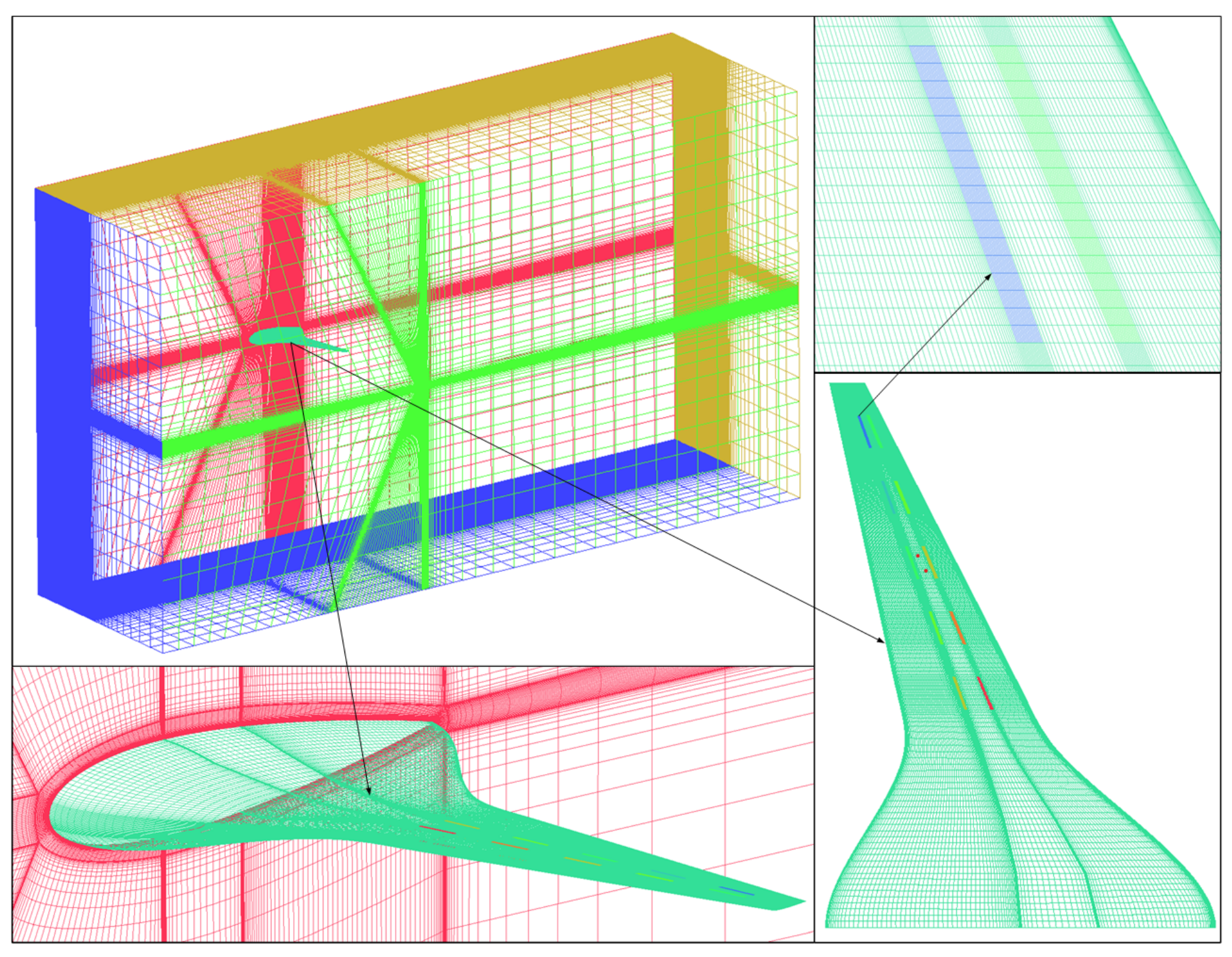
2.3. Computational Domain and Boundary Conditions

The BWB-UG equipped with the SS-AFC is divided into rectangular computational domains. The fixed semimodal numerical calculation method is used. The model is 4 L from the velocity inlet and 3 L from the upper/lower wall, as shown in Figure 2. The boundary conditions, including symmetry surfaces, velocity inlets, pressure outlets, sliding walls, and no sliding walls are set. The flow field calculation domain satisfies the far-field boundary conditions.
The computational domain of the BWB-UG is divided into high-quality hexahedral structural grids, as show in Figure 3. The mesh near the boundary layer of the BWB-UG wall and the steady-stream nozzles is encrypted to ensure that the Y + is less than 1. The number of grid units is about 5.13 million.

2.4. Validation of Numerical Calculation Method

Since the airfoil of the BWB-UG usually adopts the modified NACA airfoil, the NACA0012 standard airfoil model is used to validate the numerical calculation method. The chord length of the wing is c and the maximum thickness is 0.12 c .
The lift-to-drag characteristics of NACA0012 are solved using the established numerical flow field calculation method. By changing the angle of attack of the airfoil, the C l and C d of the airfoil at 0∼12 angle of attack are monitored, and the curve of the C l and C d changing with the angle of attack is plotted.
The numerical calculation results are compared with the experimental results in the literature [10]. The lift-to-drag ratio curve of the NACA0012 airfoil obtained by numerical calculation is consistent with the experimental results, as shown in Figure 4. This shows the feasibility of the established flow field numerical calculation method in the numerical calculation of the hydrofoil flow field and verifies that the established flow field mathematical model is reliable and accurate.

2.5. Independence Validation of Flow Field Calculation Method

Grid convergence is a necessary condition to ensure the credibility of numerical computation. The convergence of the grid is evaluated in this work by the grid convergence index (GCI). The GCI rating method was proposed by P. J. Roache [21,22]. This method requires that the computational results must satisfy the monotonic convergence condition:
0 < ( f 3 f 2 ) / ( f 2 f 1 ) < 1
where f 1 , f 2 , and f 3 are the numerically computed discrete solutions obtained through three grids ranging from rarefaction to denseness, respectively. The refinement rate of the grid is defined as
r k , k + 1 = h k h k + 1
where h is the grid feature size. In general, the value of r is less than 2. The calculation formula of GCI is:
G C I k = F s ε k . k + 1 r k , k + 1 p 1 G C I k + 1 = F s r k , k + 1 p ε k . k + 1 r k , k + 1 p 1 ε k . k + 1 = f k + 1 f k f k + 1
where F s is the grid convergence security factor; F is the numerically computed discrete solutions; r k , k + 1 is the mesh refinement ratio, which is usually required to be less than 1.2 ; and p is the convergence accuracy.
By adjustment of the distribution of the mesh nodes, four groups of meshes with different dispositions are calculated. The above four groups of grids are used to calculate the SS-AFC of the BWB-UG under 12 angle of attack. Meanwhile, the C l calculated by different grids are monitored and the corresponding GCIs are calculated; the results are shown in Figure 5. When the number of grids exceeds 5,130,000, the C l gradually stabilizes and the GCI is less than 1 % . Therefore, 5.13 million grids are chosen to simulate the SS-AFC of the BWB-UG.

3. Results and Discussion of Flow Field Calculation

3.1. Study on Steady-Suction AFC

The C L and C L of the BWB-UG before and after the installation of the steady-suction AFC are shown in Figure 6. The steady-state AFC can significantly enhance the C L of the BWB-UG and increase the stall angle from 6 to 8 with the angle of attack in the range of 0∼12 . The steady-suction AFC has a drag-reducing effect on the BWB-UG when the angle of attack is in the range of 4∼12 . When the angle of attack is 8 , the drag reduction effect is best. The drag reduction rate can reach 15.4 % .
Figure 7 compares the change in the lift-to-drag ratio of the BWB-UG before and after the installation of the steady-suction AFC. The steady-suction AFC can effectively increase the lift-to-drag ratio of the BWB-UG. The lift-to-drag ratio of the BWB-UG at 0∼12 angle of attack is significantly improved by the addition of the steady-suction AFC. The lift amplitude of the lift-to-drag ratio reaches the maximum value of 3.78 when the angle of attack is α = 8 . Under the condition of a large angle of attack range from 6∼12 , the steady-suction AFC can increase the lift-to-drag ratio of the BWB-UG by up to 45.01 % .
From the perspective of flow structure and surface pressure distribution, the impact of the steady-suction AFC on the BWB-UG is further analysed. As illustrated in Figure 8, the pressure contours of the upper and lower surfaces of the BWB-UG before and after the installation of the steady-suction AFC at three typical angles of attack of 4 , 8 , and 12 are shown. Since the steady-suction nozzles are installed for the upper surface, the steady-suction has only a slight change on the pressure of the lower surface. The distribution of the pressure on the upper surface of the BWB-UG has been significantly changed. The range of the low-pressure area at the leading edge of the wing is extended for the three angles of attack mentioned above. This increases the pressure difference between the upper and lower surfaces. As a result, the lift of the BWB-UG is improved to varying degrees. Only at the angle of attack α = 8 does the pressure area of 0 20 Pa on the lower surface increase slightly, and the pressure on the lower surface does not change significantly at other angles of attack.
The flow control mechanism is further analysed by taking the flow field characteristics of the BWB-UG before and after the installation of the steady-suction AFC at an angle of attack of 8 as an example. It can be seen from Figure 9 that there is a region of fluid countercurrent motion on the upper surface of the BWB-UG prior to the installation of the steady-suction AFC. The steady-suction AFC realizes the boundary layer suction and the upper surface turbulent vorticity reduction. After the equipment of the steady-suction AFC, the separation is eliminated or weakened, the vorticity transported to the fluid is significantly reduced, the energy dissipation of the fluid is significantly weakened, and the purpose of drag reduction is achieved. According to Figure 9, the low-velocity fluid of the boundary layer is sucked into the steady-suction nozzles, the flow rate of the boundary layer fluid is increased, and therefore, the ability to resist fluid viscosity and adverse pressure gradients is enhanced. At this time, the wall adhesion is more robust, the fluid counter current motion area is significantly reduced, and the large separation vortex is effectively suppressed. Meanwhile, the coupling effect of steady-suction flow and incoming flow gives the fluid in the wing’s leading edge higher flow velocity, so there is higher energy to overcome the flow separation. The flow separation vortex structure of the underwater glider is significantly reduced, thereby effectively improving its lift-to-drag characteristics.
As shown in Figure 10, we have carefully analysed the physical field characteristics at the steady-suction AFC nozzle. The steady-suction side is the downward flow surface. The steady-suction AFC has little effect on the pressure and velocity distribution in the local flow field. The nature of the steady-suction AFC is that it will draw energy from the flow field and weaken the energy of the local flow field. As a result, the vortex structure created by the steady-suction AFC is very small.
In summary, the hydrodynamic performance of the BWB-UG is effectively improved by being equipped with the steady-suction AFC, and the lift-to-drag ratio can be increased by up to 45.1 % . Through the analysis of the flow field structure, it can be seen that the steady-suction AFC can effectively improve the flow field structure and flow field stability. This has noticeable beneficial effects on increasing the glide ratio, improving the motion performance, enhancing the detection ability, and reducing the energy consumption of the BWB-UG.

3.2. Study on Steady-Jet AFC

The lift-to-drag ratio of the BWB-UG before and after the equipment of the steady-jet AFC is obtained in Figure 11. It can be seen that in the attack angle range of 0∼6 , the steady-jet AFC can significantly improve the lift of the BWB-UG. It is also found that when the attack angle is greater than 12 , the steady-jet AFC can significantly improve the lift. Through the analysis of the flow field structure, it is found that when the angle of attack is greater than 12 , the vortex shedding phenomenon occurs in the flow field of the BWB-UG, and the steady-jet AFC can effectively suppress this phenomenon. However, the attack angle of the BWB-UG does not exceed 12 in regular operation. Therefore, it is no longer necessary to conduct in-depth research on the total effect of the steady-jet AFC when the attack angle is above 12 . The steady-jet AFC has little effect on the resistance of the underwater glider. When the attack angle is greater than 8 , the drag reduction effect is pronounced, and the drag reduction effect is maintained at about 4 % .
As shown in Figure 12a, the steady-jet AFC significantly influences the lift-to-drag ratio. Especially in the case of low angles of attack, the improvement effect of the lift-to-drag ratio is pronounced. When the attack angle does not exceed 5 , the steady-jet AFC can effectively improve the lift-to-drag ratio of the BWB-UG. It can be seen from Figure 12b that the increased amplitude of the lift-to-drag ratio gradually decreases with the increase of attack angle, and the maximum increase amplitude of the lift-to-drag ratio is 1.56. When the attack angle exceeds 5 , the steady-jet AFC will slightly reduce the lift-to-drag ratio of the BWB-UG. The steady-jet AFC can improve the lift-to-drag ratio of the BWB-UG by 93.17 % at most. The improved hydrodynamic performance is extensively valued for its glide motion stability, real-time maneuverability, and equipment safety.
From the perspective of flow field structure and surface pressure distribution, the mechanism of steady-jet AFC on the BWB-UG is further analysed. Figure 13 shows the pressure contours of the surface of the BWB-UG at typical angles of attack before and after the installation of the steady-jet AFC. At angles of attack 4 , 8 , and 12 the effect of the steady-jet AFC on the lower surface pressure distribution is mainly reflected around the steady-jet nozzles on the wing and has little effect on the upper surface pressure distribution. The influence on the lower surface pressure distribution is mainly reflected around the steady-jet nozzles. The pressure from the steady-jet nozzles towards the leading edge is increased, while the pressure from the forward steady-jet nozzles towards the trailing edge of the wing is decreased. As the angle of attack increases, the area of high pressure on the underside gradually increases. Therefore, combined with the increase in the pressure area above 40 Pa and the change in the range of the same pressure area from 20 Pa to 0 Pa, it can be seen that the range of the pressure area increases most when the angle of attack is 4 . After equipping the steady-jet AFC at angles of attack of 8 and 12 , the depression between the pressure surface and the suction surface is slightly lower than that of the ground state due to the smaller range of the pressurization region and the larger range of the decompression region. The macroscopic manifestation is that the lift of the BWB-UG is lower than before. This is in agreement with the results of the previous studies on the lift and the drag in this work.
The lift and drag calculation results show that the steady-jet AFC, unlike the steady-suction, cannot optimise the high angle of attack hydrodynamical performance. From the perspective of the fluid-structure at the 8 angle of attack, the reason why the steady-jet AFC cannot increase the lift and reduce the drag at high angles of attack is analysed. It can be seen from Figure 14 that after the steady-jet AFC is installed on the underside of the wing, the range of the counter flow motion area above the wing of the BWB-UG is extended to varying degrees compared to that before the control. This phenomenon is most obvious in Sections 2 and 3.
As can be seen in Figure 15, after the installation of the steady-jet AFC, the high-pressure area at the leading edge of the wing increases significantly and the low-pressure area at the trailing edge decreases significantly. The pressure drag increases as the pressure differential increases. In addition, since the differential pressure resistance is greater than the frictional resistance in the total resistance of the underwater glider at the angle of attack of 8 , the total resistance of the underwater glider after the installation of the steady-jet AFC is greater than that before the application of the control. The steady-jet AFC has little effect on the velocity distribution near the upper surface of the hydroplane. However, it has a coupling effect with the incoming flow. A huge flow separation vortex is formed near the trailing edge of the wing. The separation vortex bypasses the trailing edge of the wing to interfere with the flow separation region on the upper surface of the wing, which reduces the ability of the fluid near the upper wall to resist the fluid viscosity and the inverse pressure gradient. This increases the instability of the fluid flow and expands the flow separation area. As a result, at high angles of attack, the flow field characteristics of the submersible are worse than before the control.
The physical field characteristics at the nozzle have been carefully analysed, as shown in Figure 16. The steady-jet side is the upward flow surface. The pressure and velocity distribution in the local flow field are significantly affected by the steady-jet AFC. The nature of the steady-jet AFC is to inject the energy into the flow field and perturb the local flow field. Therefore, the vortex structure created by the steady-jet AFC is very pronounced.

4. Conclusions

This paper proposes the steady-stream active control method for the underwater glider. The steady-suction and steady-jet AFC methods are investigated separately by numerical calculation methods. The effects of the steady-stream active control methods on the hydrodynamic and flow field structure of the glider are analysed. It is found that both steady-flow active control methods can significantly improve the lift-to-drag ratio of the underwater glider without changing its shape. The main conclusions are as follows:
(1) The lift-to-drag ratio of the BWB is greatly improved after the steady-suction AFC is installed. Especially at a large angle of attack, the steady-suction AFC can increase the lift-to-drag ratio of the BWB-UG by a maximum of 45.01%. In the angle of attack range 4∼12 , the steady-suction AFC will reduce the drag of the BWB-UG. When the angle of attack is 8°, the drag reduction effect is at its best, and the drag reduction rate can be as high as 15.4%.
(2) The steady-jet AFC has a significant effect on the lift-to-drag ratio. The effect of improving the lift-to-drag ratio is particularly pronounced at low angles of attack. The steady-jet AFC can improve the lift-to-drag ratio of the BWB-UG by a maximum of 93.17%. The improved hydrodynamic performance of the BWB-UG is of great value for its glide stability, real-time maneuverability, and equipment safety.

Author Contributions

Conceptualization, X.D. and X.L.; software and formal analysis, X.L.; writing, Y.S. All authors have read and agreed to the published version of the manuscript.

Funding

The author(s) disclosed receipt of the following financial support for the research, authorship, and publication of this article. This work is supported by the National Natural Science Foundation of China (No. 51979227).

Institutional Review Board Statement

Not applicable.

Informed Consent Statement

Not applicable.

Data Availability Statement

The statement does not create new data.

Conflicts of Interest

The authors declare no conflict of interest.

Nomenclatures and Abbreviations

V s t r e a m Jet/suction flow rate
θ s t r e a m Direction angle
C l Lift coefficient
C d Drag coefficient
C p Pressure coefficient
p s u r f a c e Surface pressure
p 0 Reference pressure
C v Velocity coefficient
V p o i n t Local fluid flow velocity
RLift-to-drag ratio
S h Wetted surface area
F L Lift force
F D Drag force
v Flow velocity at infinity
ρ Density of seawater
pFluid pressure
μ Dynamic viscosity coefficient
u ¯ , v ¯ , w ¯ Time-averaged velocity component
u , v , w Pulsating velocity components
S f x , S f y , S f z Generalized source terms
LSpread length of BWB-UG
fDiscrete solution of the numerical calculation;
hGrid feature size
rRefinement ratio of the grid
F s Grid convergence security factor

References

  1. D’Spain, G.L.; Jenkins, S.A.; Zimmerman, R.; Luby, J.C.; Thode, A.M. Underwater acoustic measurements with the Liberdade/X-Ray flying wing glider. J. Acoust. Soc. Am. 2005, 117, 2624. [Google Scholar] [CrossRef]
  2. Du, X.; Song, B.w.; Pan, G. Dynamics and Simulation of Underwater Glide Vehicle. In Proceedings of the 2010 International Conference on Digital Manufacturing Automation, Changcha, China, 18–20 December 2010; Volume 1, pp. 597–599. [Google Scholar]
  3. Du, X.; Ali, N. Numerical Computation of Wave Forces on Blended Winged-Body Underwater Glider using Panel Method. In Proceedings of the 2021 International Bhurban Conference on Applied Sciences and Technologies (IBCAST), Islamabad, Pakistan, 12–16 January 2021; pp. 924–931. [Google Scholar]
  4. Du, X.; Zhang, L. Analysis on energy consumption of blended-wing-body underwater glider. Int. J. Adv. Robot. Syst. 2020, 17, 1729881420920534. [Google Scholar] [CrossRef]
  5. Li, J.; Wang, P.; Chen, X.; Dong, H. Shape Optimization of Blended-Wing-Body Underwater Gliders Based on Free-Form Deformation. J. Northwestern Polytech. Univ. 2020, 38, 459–464. [Google Scholar]
  6. Sun, C.; Song, B.; Wang, P. Parametric geometric model and shape optimization of an underwater glider with blended-wing-body. Int. J. Nav. Archit. Ocean Eng. 2015, 7, 995–1006. [Google Scholar] [CrossRef] [Green Version]
  7. Sun, C.; Song, B.; Wang, P.; Wang, X. Shape optimization of blended-wing-body underwater glider by using gliding range as the optimization target. Int. J. Nav. Archit. Ocean Eng. 2017, 9, 693–704. [Google Scholar] [CrossRef]
  8. Wang, X.; Song, B.; Wang, P.; Sun, C. Hydrofoil optimization of underwater glider using Free-Form Deformation and surrogate-based optimization. Int. J. Nav. Archit. Ocean Eng. 2018, 10, 730–740. [Google Scholar] [CrossRef]
  9. Ganesh, N.; Arunvinthan, S.; Nadarajapillai, S. Effect of surface blowing on aerodynamic characteristics of tubercled straight wing. Chin. J. Aeronaut. 2019, 32, 1111–1120. [Google Scholar] [CrossRef]
  10. Fatahian, E.; Nichkoohi, A.L.; Salarian, H.; Khaleghinia, J. Effects of the hinge position and suction on flow separation and aerodynamic performance of the NACA 0012 airfoil. J. Braz. Soc. Mech. Sci. Eng. 2020, 42, 86. [Google Scholar] [CrossRef]
  11. Giorgi, M.G.D.; Luca, C.G.D.; Ficarella, A.; Marra, F.S. Comparison between synthetic jets and continuous jets for active flow control: Application on a NACA 0015 and a compressor stator cascade. Aerosp. Sci. Technol. 2015, 43, 256–280. [Google Scholar] [CrossRef]
  12. Rezaeiha, A.; Montazeri, H.H.; Blocken, B. Active flow control for power enhancement of vertical axis wind turbines: Leading-edge slot suction. Energy 2019, 189, 116131. [Google Scholar] [CrossRef]
  13. Lienhart, H.; Becker, S. Flow and Turbulence Structure in the Wake of a Simplified Car Model. SAE Trans. 2003, 112, 785–796. [Google Scholar]
  14. McNally, J.; Fernandez, E.J.; Robertson, G.; Kumar, R.; Taira, K.; Alvi, F.S.; Yamaguchi, Y.; Murayama, K. Drag reduction on a flat-back ground vehicle with active flow control. J. Wind Eng. Ind. Aerodyn. 2015, 145, 292–303. [Google Scholar] [CrossRef]
  15. Rouméas, M.; Gilliéron, P.; Kourta, A. Drag reduction by flow separation control on a car after body. Int. J. Numer. Methods Fluids 2009, 60, 1222–1240. [Google Scholar] [CrossRef]
  16. Genç, M.S.; Kaynak, U.; Yapici, H. Performance of transition model for predicting low Re aerofoil flows without/with single and simultaneous blowing and suction. Eur. J. Mech. B-Fluids 2011, 30, 218–235. [Google Scholar] [CrossRef]
  17. Huang, L.; Huang, P.G.; LeBeau, R.P.; Hauser, T. Numerical study of blowing and suction control mechanism on NACA0012 airfoil. J. Aircr. 2004, 41, 1005–1013. [Google Scholar] [CrossRef]
  18. Xu, H.Y.; Dong, Q.; Qiao, C.L.; Ye, Z. Flow Control over the Blunt Trailing Edge of Wind Turbine Airfoils Using Circulation Control. Energies 2018, 11, 619. [Google Scholar] [CrossRef] [Green Version]
  19. Yousefi, K.; Saleh, R.; Zahedi, P. Numerical study of blowing and suction slot geometry optimization on NACA 0012 airfoil. J. Mech. Sci. Technol. 2014, 28, 1297–1310. [Google Scholar] [CrossRef] [Green Version]
  20. Du, X.; Liu, X.; Song, D. Coupled physics analysis of blended-wing-body underwater glider equipped with electromagnetic active flow control. Ocean Eng. 2023, 278, 114402. [Google Scholar] [CrossRef]
  21. Baker, N.; Kelly, G.; O’Sullivan, P.D. A grid convergence index study of mesh style effect on the accuracy of the numerical results for an indoor airflow profile. Int. J. Vent. 2019, 19, 300–314. [Google Scholar] [CrossRef]
  22. Roache, P.J. Error Bars for CFD. In Proceedings of the 41st Aerospace Sciences Meeting and Exhibit, Reno, NV, USA, 6–9 January 2003; p. 2003-408. [Google Scholar]
Figure 1. Steady-stream AFC of the BWB-UG.
Jmse 11 01344 g001
Figure 2. Calculation domain and related boundary conditions of the BWB-UG.
Jmse 11 01344 g002
Figure 3. Grid meshing of the BWB-UG equipped with SS-AFC.
Jmse 11 01344 g003
Figure 4. Comparison between CFD numerical calculation results and experimental results.
Jmse 11 01344 g004
Figure 5. The curves of GCI with the number of grids.
Jmse 11 01344 g005
Figure 6. Effect of steady suction on the BWB-UG.
Jmse 11 01344 g006
Figure 7. Effect of steady-suction on the lift-to-drag ratio of the BWB-UG.
Jmse 11 01344 g007
Figure 8. Pressure contours of the BWB-UG before and after the steady-suction AFC.
Jmse 11 01344 g008
Figure 9. Pressure contours and streamline of the BWB-UG sections.
Jmse 11 01344 g009
Figure 10. Detail at the nozzle of steady-suction AFC.
Jmse 11 01344 g010
Figure 11. Effect of steady-jet AFC on the BWB-UG.
Jmse 11 01344 g011
Figure 12. Effect of steady-jet AFC on the lift-to-drag ratio of the BWB-UG.
Jmse 11 01344 g012
Figure 13. Pressure contours of the BWB-UG before and after the steady-jet AFC.
Jmse 11 01344 g013
Figure 14. The velocity distribution after the equipment of steady-jet AFC.
Jmse 11 01344 g014
Figure 15. Pressure contours and streamline of the BWB-UG sections.
Jmse 11 01344 g015
Figure 16. Detail at the nozzle of the steady-jet AFC.
Jmse 11 01344 g016
Table 1. Model design parameters.
NameValue
Spread length of UG400 mm
Maximum chord length of UG142.8 mm
Section of UGNACA0015
Length of nozzle12 mm
Width of nozzle1 mm
Number of nozzles20
Disclaimer/Publisher’s Note: The statements, opinions and data contained in all publications are solely those of the individual author(s) and contributor(s) and not of MDPI and/or the editor(s). MDPI and/or the editor(s) disclaim responsibility for any injury to people or property resulting from any ideas, methods, instructions or products referred to in the content.

