Article

Research on Energy Management for Ship Hybrid Power System Based on Adaptive Equivalent Consumption Minimization Strategy

Marine Engineering College, Dalian Maritime University, Dalian 116026, China
*
Author to whom correspondence should be addressed.
J. Mar. Sci. Eng. 2023, 11(7), 1271; https://doi.org/10.3390/jmse11071271
Submission received: 23 May 2023 / Revised: 15 June 2023 / Accepted: 18 June 2023 / Published: 22 June 2023
(This article belongs to the Section Marine Energy)

Abstract

:
This paper analyzes a hybrid power system containing a fuel cell (FC) and proposes an improved scheme involving the replacement of a single energy storage system with a hybrid energy storage system. In order to achieve a reasonable power distribution between fuel cells and energy storage units and stable operation of the power grid, an efficient energy management system (EMS) based on the equivalent consumption minimization strategy (ECMS) is proposed. To enhance the dynamic response capability of hybrid energy storage systems, a low-pass filter with a variable time constant based on the ultracapacitor SOC feedback is proposed. This paper describes the design of a fuzzy logic controller that adaptively improves the equivalent consumption minimization control strategy, adjusts the equivalent factor in real time, optimizes the operating points of the fuel cell system, and improves system efficiency. The simulation model of the fuel cell hybrid system was established using MATLAB/Simulink. The proposed adaptive equivalent consumption minimization strategy (A-ECMS) was simulated and compared to the state-based and fuzzy logic energy management systems under the simulation of the real operating conditions of the ship. The results show that the proposed strategy can maintain a fuel cell system efficiency above 60% under most operating conditions and can significantly suppress the fluctuation of a fuel cell’s output power. The proposed strategy outperforms the state-based and fuzzy logic-based EMS in terms of stabilizing the hybrid power system and reducing hydrogen consumption. The effectiveness of the proposed strategy has been verified.

1. Introduction

1.1. General

Among the existing new-energy technologies for ships, fuel cells (FCs) are recognized as the most promising clean and alternative energy source [1]. Fuel cells have the following advantages that many other conventional energy devices do not have: (1) They have less or even no polluting emissions. For example, in the case of proton exchange membrane fuel cells (PEMFC), only water is emitted, which has zero pollution characteristics. (2) They have high efficiency. Only chemical reactions occur in fuel cells, and they have no combustion process and are not limited by the Carnot cycle. (3) They exhibit low noise and vibrations. Fuel cells are power generation devices that use electrochemical principles and have no mechanical movement inside. Based on the advantages mentioned above, the fuel cell system has attracted significant attention in the development of ship load power, and it has broad market application prospects in the design and construction of both naval vessels and merchant ships.
The operating conditions of ships are complex, and their loads fluctuate greatly. Fuel cells are used in a much more complex manner on various types of ships than on the ground. For container ships, changes in load may be due to the periodic on/off switching of compressors of refrigerated containers; for bulk carriers, changes in load may be due to the operation of cargo cranes; for tankers, the load changes during cargo heating and tank degassing; for cruise ships, there are variable types of loads from auxiliary equipment. Fuel cells would reveal some disadvantages if they were used as the only source of power for a ship. The deficiencies are mainly in the following three areas: (1) They require a high initial investment. When high-powered fuel cells are used, they increase the construction costs of a ship and at the same time increase the hydrogen storage capacity on board. (2) They have poor dynamic response capabilities. When dealing with large and frequent fluctuations in the ship load, it is difficult for a fuel cell to respond quickly to the load demand, which is also not conducive to the extension of the fuel cell’s life. (3) They have no energy storage capability. Fuel cells cannot quickly suppress power fluctuations in the ship’s power grid.
Therefore, the hybrid energy storage system (HESS) is usually added to fuel cell systems to cope with the synergistic complementation between different energy power sources and to improve the overall energy efficiency of a ship. The hybrid energy storage system can be a good way to smooth out the fluctuations in ship load power [2]. The hybrid energy storage system combines the high energy density of a battery with the high power density of an ultracapacitor, allowing it to withstand frequent charging and discharging. This also allows it to suppress the low- and high-frequency powers of fluctuating loads and trigger the effects of peak and valley reduction, which can effectively reduce the impact of load fluctuation on a grid. The hybrid ship power system, composed of a fuel cell and hybrid energy storage, can make the fuel cell work better in the best operating conditions, improve its efficiency, extend its service life, enhance the dynamic response of its power system, and realize the complementary advantages of multiple power sources.
This paper is organized as follows: Section 2 describes the structural composition of the prototype hybrid power system and proposes an improved hybrid energy storage design scheme to meet the power requirements in complex scenarios. Section 3 describes the model used in the simulation. The hybrid power system was modeled in a MATLAB/Simulink simulation environment. Section 4 introduces the use of a low-pass filter to improve power allocation in energy management strategies and proposes an adaptive equivalent consumption minimization strategy (A-ECMS) based on a fuzzy logic controller. Section 5 presents the simulation results of the proposed strategy and compares it with the state-based and fuzzy logic-based EMS. Finally, Section 6 provides the concluding remarks.

1.2. Literature Review

For the marine hybrid power system, adopting a reasonable energy management strategy is key to ensuring the efficient operation of the system, reducing fuel consumption, and extending the service life of the system [3,4]. Therefore, developing a suitable EMS for the hybrid power system has been an important research topic [4,5,6].
Currently, energy management strategies mainly include rule-based strategies and optimization-based strategies. Han J. et al. proposed and validated an efficient EMS based on the operation state, which determined the operating point of each component of the system to maximize the system’s efficiency [7]. Considering a passenger ship equipped with a fuel cell hybrid power system as the research object, L. Zhu et al. adopted a fuzzy logic control strategy to further improve the performance of the energy system [8]. Gaber M. et al. proposed an energy management strategy based on an adaptive neuro-fuzzy logic control algorithm [9]. The test results on a physical platform showed that the strategy could keep the SOC of a battery within a reasonable range while suppressing the fluctuation of the bus voltage. Banaei M. et al. aimed to minimize the total operating costs of a ship and used a genetic algorithm to optimize the operation of diesel engines and lithium batteries. The feasibility of the proposed control strategy was verified using a simulation platform [10]. Hou J. et al. proposed a real-time energy management strategy based on the model predictive control of a pure electric ship and compared it to a filter-based power allocation strategy on a physical test platform. The results showed that the proposed strategy had prominent advantages in improving the reliability of a power system, extending its battery life, and improving its battery operating efficiency [11].
Based on the above research review, rule-based energy management strategies rely on expert knowledge and engineering experience and, thus, exhibit strong subjectivity and poor adaptability to real-time operating conditions, making it difficult to achieve full condition optimization. The global optimization strategy relies on global historical operating conditions, which require a large amount of computation and are not conducive to real-time online applications, making them difficult to apply in practical ship operations. The instantaneous optimization strategy requires less computation and does not require much ship condition information compared to global optimization. Its results are close to those of the global optimal algorithm, showing that it has great potential for practical applications in ships. Therefore, this article proposes an adaptive equivalent consumption minimization strategy that uses a fuzzy logic strategy to adaptively adjust the equivalent factor online. However, it is difficult to maximize the advantages of hybrid energy storage using a single instantaneous optimization algorithm. To address this issue, this paper proposes an improvement to low-pass filtering with a variable filtering time constant.

2. Description and Improvement of the Fuel Cell Boat

2.1. Descriptions of the Hybrid Power System

This paper takes the world’s first fuel cell hybrid passenger ship “Alsterwasser” as the research object. The zero-emission ships (Zemships) project developed this ship, funded by the European Union [11]. The specifications of the ship are shown in Table 1.
The ship developed a hybrid power system that involves a proton exchange membrane hydrogen fuel cell and a group of lead–acid batteries [12]. During times of high-load operation, the ship relies on the use of batteries to reduce the output power of the fuel cell and extend its lifespan. The ship is equipped with a boost DC-to-DC converter to stabilize the output voltage of the fuel cell, and the lead–gel battery is directly connected to the DC bus. The ship is equipped with an inverter system that provides AC power to the propulsion motor, rated at approximately 100 kW. The main power parameters of the ship are shown in Table 2.
The original ship used a single battery energy storage system. However, in actual ship operating conditions, the frequent fluctuations in load power have an impact, causing a single battery energy storage system to bear not only some low-frequency power but also high-frequency power, resulting in challenges for the battery in terms of lifespan and energy efficiency. There is a need to improve the existing hybrid system of the ship.

2.2. Improvement of the Hybrid Power System

Lead–acid batteries have several fundamental disadvantages as follows: a complex charge process, long recovery time, high weight (which is very important for marine vessels), and negative effects on the crew due to acid. In contrast, lithium batteries offer high energy density, long cycle life, and relatively low self-discharge rates. Hence, they are an attractive option for vehicles, including marine ships. Therefore, to improve the ship, a lithium battery is selected to replace the existing lead–acid battery. The working parameters of the chosen lithium battery are consistent with the requirements of the ship, and its output voltage is still 560 V.
The hybrid energy storage system is composed of a battery and ultracapacitor considering the high energy density and power density, which can meet the power requirements in complex scenarios [13,14]. When designing and constructing ships, designers should consider the characteristics of hybrid energy storage systems and connect some electrical equipment and devices to energy storage units. Some auxiliary equipment, such as firefighting equipment, navigation equipment, and daily lighting, are powered by batteries. Some devices are powered by ultracapacitors, such as the screw reversal mechanism and mooring equipment. Of course, most equipment with a high-power load demand is powered by hybrid systems, such as propulsion systems.
Thus, this paper proposes a hybrid energy storage system for improving the power system of the ship. An enhanced hybrid energy storage system is created by incorporating the ultracapacitor alongside a selected lithium battery. The hybrid energy storage system combines the advantages of batteries and ultracapacitors, where the battery has a high energy density but a slow response speed and can withstand low-frequency power fluctuations. In contrast, the ultracapacitor has a fast response speed and a long cycle life and can withstand high-frequency power fluctuations. Both of them jointly handle the fluctuating components of power demand, allowing the fuel cell to take the steady part of power demand, improving the efficiency of the fuel cell stack, and extending its lifespan.
In order to better suppress the load power of the ship, according to the optimization results of reference [15], the ship needs to be connected in series with at least eight sets of ultracapacitors with a rated voltage of 56 V. This paper selects the MAXWELL ultracapacitor, which forms a hybrid energy storage system with a lithium battery. The type of the ultracapacitor is “BMOD0130P056B03”, and its parameters are shown in Table 3.
The rated terminal voltage of the battery on board the prototype is 560 V, which is the same as the bus voltage setting, and a direct connection to the bus will not cause large fluctuations in the bus voltage. The semi-active structure strikes a better balance between the system controllability and improvement cost. Therefore, this paper adopts a semi-active topology for the modified hybrid energy storage system, where the ultracapacitors are connected in series with a bidirectional DC-to-DC converter to the DC bus, and the lithium battery is directly related to the DC bus. After the algorithm gives the power scheduling command, each DC-to-DC converter controls the output power of each power source and the charging and discharging status of the energy storage unit. The lithium battery is responsible for the low-frequency part of the load fluctuation, whereas the ultracapacitor copes with the high-frequency load. The goal is to ensure the fuel cell operates in a high-efficiency zone, reduce hydrogen fuel consumption, and improve the efficiency of the system. The improved hybrid power system topology is shown in Figure 1.
The balance between the generated power and load demanded control in the improved power system is shown in Figure 2. As the main power source of the system, fuel cells generate power and transmit it to the DC bus. A hybrid energy storage system composed of a battery and an ultracapacitor outputs power to the grid during discharge, and the grid can charge the energy storage system when the electricity level is low. The load of the whole ship consumes power, including the propulsion load and auxiliary load onboard.

3. Modeling of the Hybrid Energy System

3.1. Fuel Cell

This study chose the PEMFC universal model developed and validated in [18], which was validated based on experimental and actual data presented in the literature, with an error of less than ±1%. The model was implemented in Simulink, which combines the characteristics of chemical and electrical models, ignoring concentration polarization voltage loss. The parameters can be obtained from the polarization curve provided by the manufacturer. The model considers activation voltage loss and ohmic loss while ignoring concentration voltage loss. The fuel cell voltage can be defined as follows:
V fc = E o c N A ln ( i f c i 0 ) 1 s T d / 3 + 1 R o h m i f c ,
where  V fc  is output voltage;  E o c  is open circuit voltage;  N  is the number of the cells;  A  is the Tafel slope;  i f c  is the output current;  i 0  is exchange current;  T d  is stack response time;  R o h m  is internal resistance.
The open circuit voltage can be defined as follows:
E o c = K c E n ,
E n = 1.229 + ( T 298 ) 44.43 2 F + R T 2 F ln ( P H 2 P o 2 0.5 ) ,
where  K c  is voltage constant;  E n  is Nernst voltage;  F  is Faraday constant.
The hybrid power system is equipped with a set of fuel cells with a rated power of 80 kW, and the relevant parameters are shown in Table 4. The Simulink model is built according to the parameters.
Due to the existence of auxiliary equipment, consumption is also necessary to consider. Among the auxiliary equipment, the power consumed by the air compressor accounts for the largest proportion, accounting for about 93.5% of the power demanded by the auxiliary system [7,19,20,21]. Therefore, in many fuel cell efficiency studies, only compressor power consumption and stack efficiency are considered. The efficiency of the fuel cell system can be defined as follows:
η f c = P n e t P s t k / η s t k = P s t k P c p P s t k / η s t k ,
where  P n e t  is the net power of the fuel cell system;  P s t k  is stack power;  P c p  is power consumed by the air compressor;  η s t k  is fuel cell stack efficiency.
The fuel cell stack efficiency is shown in Figure 3a. It shows the relationship between the fuel cell stack efficiency and output current. As can be seen in the figure, the increase in fuel cell stack current leads to a decrease in fuel cell stack efficiency. The efficiency of the fuel cell is about 55% at a rated power of 80 kW [7]. The efficiency of the FCS strongly depends on the output power, and the auxiliary power consumption is considered in this study, as shown in Figure 3b. The maximum fuel cell system efficiency is about 64%, and the fuel cell can operate with an efficiency higher than 60% over a large range of powers. When the system operates at a meager output power (less than 3 kW), the fuel cell system efficiency is quite low [7]. To achieve good fuel economy, the fuel cell should be avoided to operate in poor-efficiency regions. Using the Lookup Table module in Simulink to create a one-dimensional interpolation module for compressor power consumption, the module can adjust the fuel cell system operating efficiency in real time according to the output power level.

3.2. Battery

Compared to traditional lead–acid batteries, lithium batteries feature high energy density, long cycle life, and a relatively low self-discharge rate. Therefore, the improved power system selects a lithium battery pack as the energy storage device. This paper adopts the equivalent model proposed in [22], which uses a controlled voltage source to simulate a change in the state of charge (SOC) of lithium batteries.
The output voltage can be defined as follows:
V batt = E b a t t r b a t i ,
where  E b a t t  is open circuit voltage;  r b a t  is the internal resistance of the battery;  i  is the current of the battery. It is assumed that the value of the internal resistance is constant.
The value of battery voltage in the charge and discharge mode is calculated by
E b a t , charge = E 0 K Q 0.1 Q + Q t i * K Q Q Q t Q t + A exp ( B Q t ) ,
E b a t , discharge = E 0 K Q Q Q t i * K Q Q Q t Q t + A exp ( B Q t ) ,
where  E 0  is constant voltage;  K  is polarization constant;  Q  is maximum battery capacity;  Q t  is actual battery charge;  i *  is low-frequency current dynamics;  A  is exponential voltage;  B  is exponential capacity.
The SOC of the battery is denoted by
S O C = Q t Q × 100 % = Q 0 0 t i d t Q × 100 % ,
The C rate is defined as follows:
C = i Q / t ,
For the battery bank chosen, there are three packs running in parallel, with each pack containing twelve modules of 48 V/60 Ah arranged in series. The parameters are listed in Table 5.
The lithium battery model was validated according to the reference [22]. When the battery operates normally and the state of charge (SOC) is between 20% and 100%, the error between the simulated voltage and the actual voltage is within ±5%. After the battery SOC is as low as 10%, the error exceeds 5%. However, in actuality, the energy management strategies consider the service life of the battery and limit its excessive discharge, ensuring that the SOC of the battery is not less than 10%, so the model error of the battery does not exceed 5% at normal conditions. Therefore, the model can simulate the actual variation in the battery pack better.

3.3. Ultracapacitor

An equivalent circuit model usually models the ultracapacitor model to simulate its charging and discharging characteristics, and the ultracapacitor model used in this paper is the internal resistance equivalent model proposed in [20]. It is composed of a controlled voltage source with a series resistor. The model is integrated into the Simulink/Simscape library, and the parameters are set according to Table 3.
The following equation can express the terminal voltage:
U u c = N s Q T d N p N e ε ε 0 A i + 2 N e N s R T F a r s i n h ( Q T N p N e 2 A i 8 R T ε ε 0 c ) R uc i u c ,
where  N s  is the number of ultracapacitor in series;  Q T  is the electric charge;  d  is molecular radius;  N p  is the number of ultracapacitors in parallel;  N e  is the number of electrode layers;  ε  is material permittivity;  ε 0  is vacuum permittivity;  A i  is the internal contact area of electrolyte and electrode;  R  is Ideal gas constants;  T  is operating temperature;  c  is volumetric molar concentration;  R uc  is internal resistance;  i u c  is output current.
The SOC of the ultracapacitor can be defined as follows:
S O C U C = Q i n i t 0 t i u c d t Q T × 100 % ,
where  Q i n i t  is the initial electric charge.

3.4. DC-to-DC Converter

The fuel cell has a large output voltage variation during operation, which needs to stabilize the terminal voltage and regulate its output current. The boost converter is in series with the fuel cell to control the energy flow between the fuel cell and the DC bus [23].
A bidirectional DC-to-DC converter connects the energy storage unit to the DC bus. The operating state is switched according to the command to change the current direction and control the power level. A half-bridge non-isolated bidirectional DC-to-DC converter is used here. Its topology is shown in Figure 4 I b a t  is the current flowing through the energy storage unit;  U b u s  is the output voltage of the converter;  U b a t  is the voltage at the output of the energy storage unit; V1 and V2 indicate insulated gate bipolar transistor (IGBT); D1 and D2 are anti-parallel diodes; L and C indicate the energy storage inductor and the bus connection capacitor. The operating mode of the buck–boost converter is achieved by controlling the duty cycle of the IGBT, which is controlled by the pulse width modulation (PWM).
Since the fuel cell does not require bidirectional control, a boost converter is used to boost the terminal voltage to the DC bus voltage; its topology is shown in Figure 5. The duty cycle of the IGBT transistor can be adjusted to achieve the charging and discharging current, the voltage control of the energy storage unit, and the boost control of the fuel cell.
According to the DC-to-DC converter operation principle and topology, bidirectional DC-to-DC converter and boost DC-to-DC converter models can be built using MATLAB/Simulink.

3.5. Load Power

An extract of the power requirements for a typical voyage on the Alster, Hamburg, Germany, was measured and published in [7,24]. This power requirement includes propulsion and auxiliary power in the whole ship [7]. The maximum demanded power of the ship is about 112 kW [25]. The power required for sailing is about 50 kW. The power demand of a typical voyage includes various operating states of the ship, which is representative and has been widely used in simulation research on hybrid power ships [7,24,25]. It should be noted that this power demand only partially represents the normal commercial operation of the ship, as the boarding and disembarking of passengers need to be taken into account during the commercial process, which will prolong the berthing time.
The data of load power measured from [7] shown in Figure 6 starts with a cruising time of about 90 s; the ship then enters a docking phase lasting 45 s. The vessel is alongside for 25 s. Finally, the ship starts to sail again and reaches its cruising speed after an acceleration of about 35 s, needing a total time of 300 for the maneuver.
The electrical load of a ship is related to the operating conditions and environmental factors, making it difficult to derive an accurate formula for calculation. However, the electrical load is fundamental in validating the energy management strategy, so an equivalent load model is needed. This paper uses the DC controllable load to replace the ship load link from the ship propulsion system to the DC-to-AC inverter. A one-dimensional interpolation table was generated using the actual load data of the typical working conditions of the prototype ship. In the simulation, the value of the load power is divided by the value of the bus voltage to obtain the input value of the controllable DC source.

4. Energy Management Strategy

4.1. Equivalent Consumption Minimization Strategy

The equivalent consumption minimization strategy (ECMS) was first proposed by Paganelli G. et al. in their research on the energy management strategy for hybrid electric vehicles [26]. It is derived from Pontryagin’s Minimum Principle (PMP). The optimal control based on PMP can be implemented in real-time applications because it is instantaneous [27,28]. The PMP is proposed for solving optimization problems in which the permissible control belongs to the closed set and can be used not only for the optimal control of continuous issues but also for the optimal control of discrete problems.
For the hybrid system energy management problem studied in this paper, the state variable  x ( t )  is the SOC of the energy storage unit, and the control variables  u ( t )  are the output power of the fuel cell, the battery, and the ultracapacitor. The objective function is the hydrogen fuel consumption, which can be defined as follows:
J ( u ) = t 0 t f [ m H 2 ( u ( t ) ) ] 2 d t ,
where  m H 2 ( u ( t ) )  indicates the instantaneous hydrogen consumption of the whole power system.
The constraints are as follows:
P uc min P u c P u c max ,
P b a t t min P b a t t P b a t t max ,
P f c min P f c P f c max ,
S O C b a t t min S O C b a t t S O C b a t t max ,
S O C u c min S O C u c S O C u c max ,
P l o a d = P s t o r + P f c = P b a t t + P u c + P f c ,
The Hamiltonian function can be defined as follows:
H ( x , λ , u ) = λ ( t ) · f ( x , u , t ) + m f c , H 2 ( u ) ,
The physical meaning of the first term on the right side of the equation is expressed as the equivalent fuel hydrogen consumption of the energy storage unit. The physical definition of the co-state variable ( λ ) can be represented as an equivalent coefficient between the change in electrical energy in the energy storage unit and the use of hydrogen; that is, the consumption of electrical energy is regarded as hydrogen consumption in the future.  m f c , H 2 ( u )  is the instantaneous hydrogen consumption of the fuel cell.
In the equivalent consumption minimization strategy, to show the relationship between electrical energy and hydrogen consumption intuitively, the equivalent factor, or penalty factor, is usually defined, which is used to replace the covariates in the Hamiltonian function. If the charging and discharging efficiency of the energy storage unit is also considered, the equivalent hydrogen combustion part of the energy storage unit in the Hamiltonian function can be defined as follows:
m s t o r ( P s t o r ( t ) ) = k · s · P s t o r ( t ) η s t o r q l h v + ( 1 k ) · s · η s t o r · P s t o r ( t ) q l h v ,
where  k  indicates the operating status of the energy storage unit while charging:  k = 0 , while discharging  k = 1 ; s is the equivalent factor;  P s t o r ( t )  is the energy storage power;  η s t o r  is the charging or discharging efficiency;  q l h v  is the lower heating value of hydrogen; here, 120 kJ/kg was taken.
Usually, the equivalent factor ( s ) is set as a constant or expressed as a function of the charge state of the energy storage unit, as shown in Equation (21).  μ  is the SOC balance coefficient of the ultracapacitor.
s = 1 2 μ ( S O C 0 . 5 ( S O C max + S O C min ) ) S O C max S O C min ,
The equivalent factor directly affects the operating efficiency of the fuel cell and the SOC of the energy storage units. Therefore, the equivalent factor must be continuously adjusted according to the changing operating conditions and the charge state of the energy storage unit to improve the optimized performance of the equivalent consumption minimization strategy. The next section will improve the equivalent consumption minimization strategy.

4.2. Improvement of Equivalent Consumption Minimization Strategy

4.2.1. Improvement on Low-Pass Filter with Variable Time Constant

A single control algorithm cannot consider the difference between the power density and energy density of different energy storage units. The power cannot be decomposed according to the frequency characteristics. Hence, this paper uses a first-order low-pass filter (LPF) to divide the load into high-frequency and low-frequency power. The low-frequency part is fed into the ECMS algorithm, which determines the optimal control sequence that satisfies the boundary conditions and outputs the reference power of the fuel cell and the battery. The ultracapacitor takes care of the high-frequency part, and when the ultracapacitor executes the load command directly from the low-pass filter, overcharge and overdischarge problems occur [29]. Therefore, a control strategy based on the feedback of the ultracapacitor charge state must be added after the LBF to ensure that the ultracapacitor charge state is always within the normal operating range.
In the optimization control of hybrid storage systems based on SOC feedback, there are mainly rule-based control strategies [27,29], model predictive control [30,31], and fuzzy logic control [32,33]. The Model predictive control strategy relies on accurate circuit models and has poor robustness. The fuzzy logic control strategy depends on expert experience, which affects the control accuracy. The rule-based control strategy has simple control logic and strong practicality [34], so the rule-based control strategy is adopted in this section.
The rule-based strategy divides different operating state points based on the present SOC of the energy storage system and then controls the proper operation of the system. The rule-based control strategy usually adopts the variable filtering time constant method for the recovery control of the state of charge of supercapacitors ( S O C u c ) [27]. The time constant of the low-pass filter is adaptively adjusted according to the charge state of the ultracapacitor. When the ultracapacitor is fully charged, the high-frequency power response is increased; when it is undercharged, the high-frequency power response is reduced, or a charging operation is performed. The  S O C u c  is guaranteed to be within the normal range to prevent overcharge or overdischarge. Here, a distinction was made between the positive and negative reference output power of the ultracapacitor.
The first-order low-pass filter is the most widely used power distribution method. The transfer function can be represented as follows:
H ( s ) = 1 1 + s T ,
where s is a complex variable;  T  is the filter time constant. The value of  T  can be set according to the size of the high-frequency component of the load carried by the ultracapacitor; the larger the value of  T , the better the suppression of fluctuations.
According to the typical operating area division of  S O C u c , it can be divided into five intervals, as shown in Figure 7.
The principle of the secondary adjustment of the filtering time constant in the operating state in each interval is as follows:
(1)
Overcharge area:  S O C u c > S O C max , when the high-frequency power is positive, the filter time constant should be increased to increase the discharge power; when the high-frequency power is negative, the constant should be set to 0 to prohibit its charging operation. The adjustment amount is given by
{ T = T 0 + Δ T d i s , max , P * 0 T = 0     , P * < 0 ,
where  T 0  is the initial value of the filter time constant;  Δ T d i s , max  is the maximum increment of filter time constant during discharging, which is up to the maximum output power of ultracapacitor;  P *  is the reference value of the output power of ultracapacitor; a positive value means discharging, and a negative value means charging.
(2)
Charging warning area:  S O C h i g h < S O C u c S O C max , the ultracapacitor is fully charged. In the case of a rapid increase in the load, the filter time constant should be increased to increase the discharging power; in the case of a rapid decrease in the load, the constant should be reduced to reduce the charging power. The adjustment amount is given by
{ T = T 0 + Δ T d i s , max ( S O C s c S O C h i g h S O C max S O C h i g h ) , P * 0 T = T 0 T 0 ( S O C s c S O C h i g h S O C max S O C h i g h ) , P * < 0 ,
(3)
Normal operating area:  S O C l o w S O C u c S O C h i g h , the constant is not adjusted, and the ultracapacitor is operated normally for charging or discharging.
(4)
Discharging warning area:  S O C min S O C u c < S O C l o w , in this case, the constant should be reduced in the case of a rapid increase in the load to minimize the amount of discharge; in the case of a rapid decrease in the load, the constant should be increased to increase the charging power.
{ T = T 0 T 0 ( S O C s c S O C min S O C l o w S O C min ) , P * 0 T = T 0 + Δ T c h a , max ( S O C s c S O C h i g h S O C l o w S O C min ) , P * < 0 ,
where  Δ T c h a , max  is the maximum increment of the filter time constant during charging up to the maximum charging power of the ultracapacitor.
(5)
Overdischarging area:  S O C u c < S O C min , when the power is positive, the constant becomes 0; the low-pass filter has no effect; when the reference power is negative, the constant is increased. The adjustment amount is given by
{ T = 0     , P * > 0 T = T 0 + Δ T c h a , max , P * 0 ,
Here, the proposed low-pass filter control method with variable filtering time constants is simulated and verified. The initial SOC is 15% and SOC is 85%, and the initial SOC of the battery is 65%; after the simulation, the change diagram of the SOC and the output power are obtained. When the initial SOC = 15%, it is at the discharging warning area. According to the adjustment filter time constant scheme proposed above, if the power is less than zero, the filter time constant is increased; that is, the charging power is increased. If the load power is greater than zero, the filter time constant is reduced; that is, the discharge power is reduced.
Figure 8a verifies the strategy designed in this paper by increasing the filter time constant to 90 s and decreasing it to 102 s. Additionally, at 200 s, the filter time constant was adjusted to the initial value again because the SOC of the ultracapacitor had increased to more than 20% and was in the normal area. When the initial SOC = 85% of the ultracapacitor is in the charging warning area, the reference power is greater than zero, and the filter constant should be increased, i.e., the discharge power of the ultracapacitor should be increased. From the partial enlargement of Figure 8b, it is obvious that when the reference power is greater than zero, the area enclosed by the dashed line and the x-axis is significantly larger than the area enclosed by the solid line. Additionally, when the reference power is less than zero, the area enclosed by the dashed line and the x-axis is obviously smaller than that enclosed by the solid line.
The simulation experiments verify the proposed first-order low-pass filter control strategy, which can effectively avoid the overcharge and overdischarge phenomena and give full play to the characteristics of ultracapacitors absorbing high-frequency power.

4.2.2. Adaptive Improvement of Equivalent Consumption Minimization Control Strategy

As can be seen from the Hamiltonian function, the optimization problem equates the power consumption of the energy storage unit to the hydrogen fuel consumption of the fuel cell, and the equivalent factor reflects the relationship between the conversion of electrical energy and fuel consumption. If the equivalent factor is large, the system tends to expect the fuel cell to bear more power; if it is small, the system expects the energy storage unit to consume more power. The selection of the equivalent factor is crucial for the optimal operation of the whole system, and the selection of the equivalent factor should consider both the SOC of the energy storage unit and the efficiency of the fuel cell operating conditions.
Determining the equivalent factor significantly influences the equivalent consumption minimization strategy results, so selecting the optimal or near-optimal equivalent factor is crucial for the energy management strategy. The optimal equivalent factor is related to the ship’s operating conditions. The focus is on how to determine the equivalent factor based on the SOC of the battery, and the operating conditions of the ship. The adaptive equivalent consumption minimization strategy (A-ECMS) differs from the traditional ECMS strategies. The search for the optimal control sequence is accomplished by replacing a single constant equivalent factor with an equivalent factor that changes in real time.
Fuzzy logic control adaptively adjusts the equivalent factor in the equivalent consumption minimization strategy, which does not rely on accurate mathematical expressions and has strong fault tolerance and robustness. To improve the operating point of the fuel cell and further reduce the hydrogen fuel consumption under the condition of ensuring the stability of the SOC of the energy storage unit, an A-ECMS based on fuzzy logic control to adjust the equivalent factor online is developed.
The fuzzy logic controller designed in this paper adopts a dual-input single-output structure. As shown in Figure 9, the deviation between the SOC feedback and the reference value of the battery ( Δ S O C ) and the output power of the fuel cell ( P f c ) is used as the input variable; the output is the adjustment of the equivalent factor ( Δ s ). The following formula can be used to obtain the equivalent factor at time  t + 1 :
s ( t + 1 ) = s ( t ) + Δ s ( t + 1 ) ,
The quantization factor and reference value of the SOC of the battery are set to 0.01 and 0.6, respectively. The fuzzy domain of the battery SOC is from −0.6 to 0.4. There are seven membership functions for  Δ S O C , including NB (Negative Big), NM (Negative Medium), NS (Negative Small), Z (Zero), PS (Positive Small), PM (Positive Medium), and PB (Positive Big). The adjustment amount of the equivalent factor is defined as [−0.3, 0.3] in the fuzzy domain. There are five membership functions, A, B, C, D, E, F, and G. According to the efficiency curve of the fuel cell system, the fuel cell power output is divided into three efficiency intervals: low, medium, and high, as shown in Figure 10. The low-efficiency interval is [0, 5] kW and [65, 80] kW when the efficiency is below 55%; the medium-efficiency interval is [5, 10] kW and [50, 65] kW when the efficiency is between 55% and 60%; and the high-efficiency interval is [10, 50] kW when the efficiency is greater than 60%. The fuzzy subsets of the five intervals from the smallest to largest power are denoted as {FA, FB, FC, FD, FE}. Triangular and trapezoidal membership functions are chosen for the fuzzy inputs and outputs, as shown in Figure 11.
Table 6 shows the IF-THEN rules for the fuzzy logic controller. When  Δ S O C  is larger, the SOC is greater than the set value, and the equivalent factor should be reduced, which reduces the power output cost of the lithium battery. When  Δ S O C  is smaller, the SOC is less than the set value, increasing the equivalent factor, increasing the power output cost of the battery, and reducing the power output of the battery. When the fuel cell output power is not in the high-efficiency interval, the equivalent factor should be reduced or increased appropriately to move its operating point toward the high-efficiency operating interval.

5. Simulation Results

In this study, the software used for simulation and validation is MATLAB R2022b. The hybrid power system of the ship is modeled mathematically and implemented in a Simulink environment using the Simscape Power Systems (SPS) toolbox. The simulation model of the hybrid power system consists of a fuel cell system, battery, load power requirement subsystem, and energy management subsystem. The energy management subsystem includes the proposed adaptive equivalent consumption minimization strategy, the state-based strategy in [29], and the fuzzy logic-based strategy in [8]. The simulation time is set to 300 s, the simulation type is discrete, and the sampling time is 5 × 10⁻⁵ s. During simulation, three strategies are called separately to analyze the control effect of the adaptive equivalent consumption minimization strategy. In addition, an analysis of the hydrogen consumption and operation cost of the adaptive equivalent consumption minimization strategy was validated through a comparative analysis.
When the state-based strategy is simulated and validated, reference [7] defines the range of the initial battery SOC as normal SOC (50–80%) and low SOC (<50%). This definition is also used for the initial battery SOC in this paper to ensure variable consistency during strategy validation and comparative analysis. When validating the three strategies, selecting an initial SOC of 65% and 25% represents the initial state of “normal SOC” and “low SOC”, respectively. In the first case, the initial battery SOC is 65%. It means that the battery begins to work with a normal SOC. Therefore, the fuel cell works mostly at the command of the load power and sometimes at the optimum power. In the second case, the initial battery SOC is 25%, so the battery begins working with a low SOC. The fuel cell will try to charge the battery to increase the SOC if the load is not too high. The simulation mainly investigates the fluctuation of the output power of the fuel cell, the change in the fuel cell system efficiency, the fluctuation of the output power, and the C-rate of the battery. The initial SOC of the ultracapacitor is set at 70%. The simulation results are presented in Figure 10.
When using the state-based strategy, with an initial battery SOC of 65%, as shown in Figure 12a,b, the output power of the fuel cell fluctuates significantly during maneuvering at 100–150 s, but the fuel cell efficiency can still be above 60% most of the time; when the ship accelerates, the fuel cell efficiency drops to below 50%. As shown in Figure 12c, the output power fluctuation frequency of the battery is relatively high, which undertakes the high-frequency power. The composite energy storage units do not fully utilize the advantages.
According to Figure 12a,b, compared to the state-based control strategy, when using the fuzzy logic strategy, the fluctuation amplitude of the output power of the fuel cell is reduced, and the efficiency of the fuel cell system is roughly maintained at over 50%. However, as shown in 
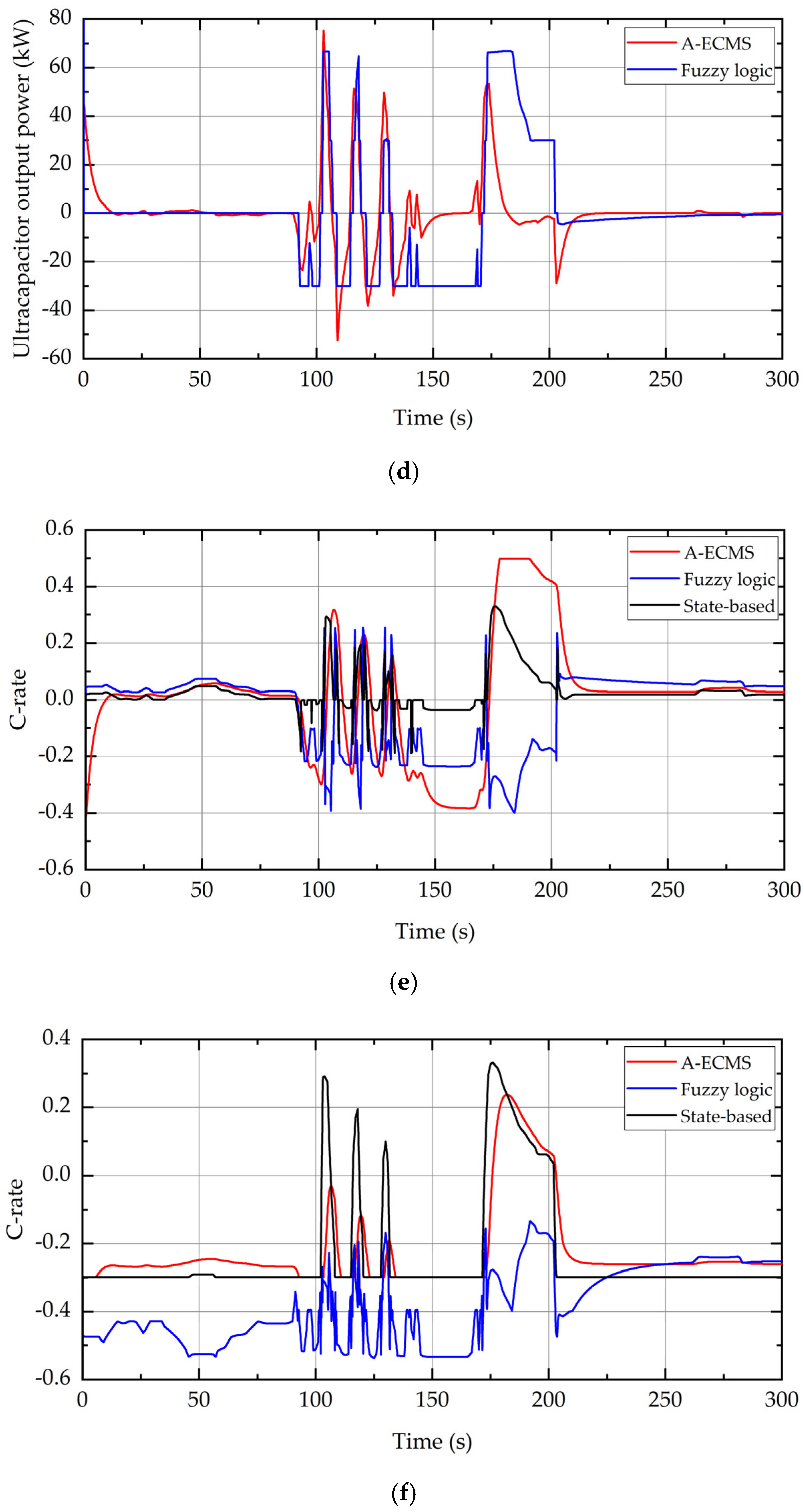
Figure 12c, the output power fluctuation frequency of the battery is relatively high, and the batteries bear some high-frequency load power fluctuations. Frequent charging or discharging greatly affects the service life of the battery. The power fluctuation of the ultracapacitor is not significant, which only shares a portion of the high-frequency power, as shown in Figure 12d. Apparently, the system does not take full advantage of the ultracapacitor.
As can be seen from Figure 12a,b, based on the adaptive equivalent consumption minimization strategy proposed in this paper, the output power of the fuel cell fluctuates only at the moment of maximum load demand when the initial SOC of the battery is 65%, and the system efficiency is maintained roughly above 60%. The improvement in fuel cell efficiency during the full simulation time is better than that of the state-based control method. According to Figure 12e,f, when the initial SOC of the battery is 65% and 25%, the adaptive equivalent consumption minimization strategy can control the C rate of the battery within 0.3. Compared to the other two strategies, the fluctuation frequency of the C-rate is relatively small, especially when the initial SOC of the battery is 25%; that is, the quantity of electric charge of the battery is low, and the battery is charging at a C rate of 0.3 most of the time. Only when the load power is greater than the maximum output power of the fuel cell will the system give up mandatory battery protection and meet the load demand preferentially. Furthermore, the addition of a low-pass filter makes the output power fluctuation of the ultracapacitor more severe. In contrast, the power fluctuation of the battery is relatively small, which reflects the full utilization of the advantage of composite energy storage units in the system.
Through comprehensive simulation experiments, the following can be concluded: (1) The hybrid energy storage unit reduces the current fluctuation frequency of the battery, which can effectively prolong the service life of the battery. The frequency division function of the low-pass filter also gives full play to the respective working characteristics of lithium battery and ultracapacitor, effectively smoothing the fluctuation of ship load power. (2) When the initial state of the battery is at “normal SOC”, that is, the initial battery SOC is between 50% and 80%, the adaptive equivalent consumption minimization strategy is superior to the control strategy based on state-based and fuzzy logic in suppressing the fluctuation of fuel cell output power. The operating efficiency of the fuel cell system is controlled above 60% most of the time, which effectively improves the economy of the hybrid power system. (3) When the initial lithium battery SOC is 25%, and the battery is at low SOC, A-ECMS outperforms the state-based strategy in controlling fuel cell efficiency, as shown in Figure 12g. However, the simulation results show that the fuzzy logic strategy is superior to the A-ECMS strategy in maintaining the efficiency and stability of the fuel cell system. The difference is that the fuzzy logic strategy prioritizes the efficient operation of the fuel cell, whereas the A-ECMS strategy prioritizes charging the battery. At this time, the low-frequency load is jointly borne by the fuel cell and lithium battery.
The following is an analysis of the hydrogen consumption and operation cost of the hybrid power system. According to the simulation verification in the previous section, the hydrogen consumption simulation comparison of each control strategy under the 300 s simulation condition can be obtained. Figure 13 shows a comparison of the hydrogen consumption for each strategy when the initial SOC of the battery is 65%. The comparison strategies in Figure 11 are the traditional load command tracking control [7], the state-based strategy [35], the fuzzy logic control strategy [8], and the adaptive equivalent consumption minimization strategy proposed in this paper. It can be seen from Figure 13 that the adaptive equivalent consumption minimization strategy is superior to the other control strategies in controlling hydrogen consumption.
In comparing the operating costs, the operating cost is the sum of the hydrogen consumption cost and the electricity consumption cost of the energy storage unit. The operational cost comparison is based on the European hydrogen price of 4.823 USD/kg and the 24-h average electricity price of 0.284 USD/kWh provided in [35]. Table 7 shows that the hydrogen consumption and operating cost of the adaptive equivalent consumption minimization strategy are lower than the other two control strategies. In the proposed strategy, the variation coefficient of the fuel cell operation efficiency and the standard deviation of the output power are lower than those of the others. The mean value of operating efficiency is higher. This indicates that the adaptive equivalent consumption minimization strategy is better than the state-based strategy and the fuzzy logic strategy in terms of the control effect of improving the operation efficiency and stabilizing the power fluctuation of the fuel cell.
The control effect of the adaptive equivalent consumption minimization strategy in reducing hydrogen consumption and operating cost is mainly due to the following: (1) the design of the adaptive equivalent factor makes the fuel cell operate in the high-efficiency range under most operating conditions, and the operating economy is improved; (2) the low-pass filter with variable filtering time constant can give full play to the characteristics of the ultracapacitor, which takes up the high-frequency power part of the load and reduces the output power fluctuation of the fuel cell and lithium battery.

6. Conclusions

This study considered the fuel cell hybrid ship as the research object. Fuel cells are recognized as the most promising clean energy source among the existing new energy technologies for ships. The fuel cell ensures the operation of a power plant without the emission of nitrogen oxides NOX, sulfur oxides SOX, and carbon oxides CO, which are toxic gases. To meet the power requirements in complex scenarios and balance the characteristics of high energy and high density in the power system, this study improves the existing hybrid power system of the ship by adding ultracapacitors to form a hybrid energy storage system with a lithium battery. For an improved fuel cell hybrid system, this paper proposes an adaptive equivalent consumption minimization strategy for energy management. To compensate for the shortcomings of the equivalent consumption minimization strategy in improving the dynamic response speed of hybrid energy storage systems, this paper proposes a low-pass filter with a variable time constant based on the ultracapacitor SOC feedback. In order to determine the optimal equivalent factor in real time during ship operation to ensure efficient energy management of hybrid power systems, this paper proposes an adaptive equivalent consumption minimization strategy based on a fuzzy logic control strategy.
Under the same load power, this paper compares the proposed adaptive equivalent consumption minimization strategy with the state-based strategy and fuzzy logic strategy. When using the other two strategies, the power of the fuel cell fluctuates between 10 and 80 kW, and the operating efficiency fluctuates between 45 and 65%. However, the proposed strategy can effectively control the efficiency of the fuel cell to be above 60%, operate smoothly with an output power of 45 kW, and only produce acceptable fluctuations when the load demand is maximum. By adopting the proposed strategy, the power fluctuation of supercapacitors is more severe, but the power fluctuation of lithium batteries is smaller. This reflects the control effect of a variable time constant first-order low-pass filter based on supercapacitor SOC feedback, fully leveraging the advantages of composite energy storage units. The C rate of a lithium battery can be controlled within 0.3. This helps to extend the service life of the battery.
When the initial SOC of a lithium battery is low (<50%), the adaptive equivalent consumption minimization strategy prioritizes charging the battery. At this point, the low-frequency load is jointly borne by the fuel cell and the lithium battery. When the battery is within the normal SOC range, and the SOC is between 50% and 80%; that is, when the energy storage system is in a normal state, the optimization control effect of the proposed strategy is the most effective, which is consistent with the normal operating state of the ship. In terms of cost comparison, compared to the other two strategies, the adaptive equivalent consumption minimization strategy significantly reduced the operational cost and hydrogen consumption by about 9% and 0.6%, respectively. The proposed strategy has significant control effects on both the stable operation and the costs of the fuel cell hybrid power system.
In summary, the proposed adaptive equivalent minimization consumption strategy is significantly superior to the state-based and fuzzy logic strategy in saving hydrogen consumption, controlling operating costs, and suppressing power fluctuations in hybrid power systems. The proposal and validation of the strategy provide a better solution for the energy management strategy design of hybrid fuel cell vessels. With a background of zero pollution and emissions, this study can provide a theoretical reference for designing a new energy ship power system.

Author Contributions

Conceptualization, Y.G., K.Z. and J.Z. (Jundong Zhang); methodology, Y.G.; software, Y.G. and Y.W.; validation, Y.G. and K.Z.; formal analysis, Y.G.; writing—original draft preparation, Y.G.; writing—review and editing, Y.G.; visualization, Y.G. and J.Z. (Jinting Zhu); supervision, J.Z. (Jundong Zhang); project administration, J.Z. (Jundong Zhang); funding acquisition, J.Z. (Jundong Zhang). All authors have read and agreed to the published version of the manuscript.

Funding

This research was funded by the National Key R&D Program of China, grant number 2022YFB4301400, and the High-technology Ship Research Program, grant number CBG3N21-3-3.

Institutional Review Board Statement

Not applicable.

Informed Consent Statement

Not applicable.

Data Availability Statement

Not applicable.

Acknowledgments

We would like to thank the editor and the anonymous reviewers for their valuable comments and suggestions.

Conflicts of Interest

The authors declare no conflict of interest.

References

  1. Azzara, A.; Rutherford, D.; Wang, H. Feasibility of IMO Annex VI Tier III Implementation Using Selective Catalytic Reduction. Int. Counc. Clean Transp. 2014, 4, 1–9. [Google Scholar]
  2. Hou, J.; Sun, J.; Hofmann, H.F. Mitigating Power Fluctuations in Electric Ship Propulsion with Hybrid Energy Storage System: Design and Analysis. IEEE J. Ocean. Eng. 2018, 43, 93–107. [Google Scholar] [CrossRef]
  3. Bassam, A.M.; Phillips, A.B.; Turnock, S.R.; Wilson, P.A. An improved energy management strategy for a hybrid fuel cell/battery passenger vessel. Int. J. Hydrogen Energy 2016, 41, 22453–22464. [Google Scholar] [CrossRef] [Green Version]
  4. Stamatakis, M.E.; Ioannides, M.G. State Transitions Logical Design for Hybrid Energy Generation with Renewable Energy Sources in LNG Ship. Energies 2021, 14, 7803. [Google Scholar] [CrossRef]
  5. Torreglosa, J.P.; Garcia, P.; Fernandez, L.M.; Jurado, F. Predictive Control for the Energy Management of a Fuel-Cell-Battery-Supercapacitor Tramway. IEEE Trans. Ind. Inform. 2014, 10, 276–285. [Google Scholar] [CrossRef]
  6. Xu, L.; Ouyang, M.; Li, J.; Yang, F.; Lu, L.; Hua, J. Optimal sizing of plug-in fuel cell electric vehicles using models of vehicle performance and system cost. Appl. Energy 2013, 103, 477–487. [Google Scholar] [CrossRef]
  7. Han, J.; Charpentier, J.-F.; Tang, T. An Energy Management System of a Fuel Cell/Battery Hybrid Boat. Energies 2014, 7, 2799–2820. [Google Scholar] [CrossRef] [Green Version]
  8. Zhu, L.S.; Han, J.G.; Peng, D.K.; Wang, T.Z.; Tang, T.H.; Charpentier, J.F. Fuzzy logic based energy management strategy for a fuel cell/battery/ultra-capacitor hybrid ship. In Proceedings of the International Conference on Green Energy, Sfax, Tunisia, 25–27 March 2014. [Google Scholar]
  9. Gaber, M.; El-Banna, S.H.; El-Dabah, M.; Hamad, M.S. Intelligent Energy Management System for an all-electric ship based on adaptive neuro-fuzzy inference system. Energy Rep. 2021, 7, 7989–7998. [Google Scholar] [CrossRef]
  10. Banaei, M.; Ghanami, F.; Rafiei, M.; Boudjadar, J.; Khooban, M.-H. Energy Management of Hybrid Diesel/Battery Ships in Multidisciplinary Emission Policy Areas. Energies 2020, 13, 4179. [Google Scholar] [CrossRef]
  11. Hou, J.; Song, Z.; Park, H.; Hofmann, H.; Sun, J. Implementation and evaluation of real-time model predictive control for load fluctuations mitigation in all-electric ship propulsion systems. Appl. Energy 2018, 230, 62–77. [Google Scholar] [CrossRef]
  12. Zemships—Zero Emission Ships. One Hundred Passengers and Zero Emissions: The First Ever Passenger Vessel to Sail Propelled by Fuel Cells. Available online: http://ec.europa.eu/environment/life/project/Projects/index.cfm?fuseaction=home.showFile&rep=file&fil=Zemships_Brochure_EN.pdf (accessed on 9 January 2013).
  13. Ma, C.; Dong, S.; Lian, J.; Pang, X. Multi-Objective Sizing of Hybrid Energy Storage System for Large-Scale Photovoltaic Power Generation System. Sustainability 2019, 11, 5441. [Google Scholar] [CrossRef] [Green Version]
  14. Zhang, Z. Study on Sizing and Energy Management Strategy of Hybrid Energy Storage System for Hybrid Ship. Master’s Thesis, Wuhan University of Technology, Wuhan, China, 2019. (In Chinese). [Google Scholar]
  15. Maxwell Technologies. Ultracapacitor BMOD0130P056B03 Datasheet. Electronic Components Datasheet Search. Available online: https://pdf1.alldatasheet.com/datasheet-pdf/view/558275/MAXWELL/BMOD0130P056B03.html (accessed on 30 March 2023).
  16. Wu, S. Study on Energy Management and Control Strategy of Hybrid Ship. Master’s Thesis, Wuhan University of Technology, Wuhan, China, 2020. (In Chinese). [Google Scholar]
  17. Souleman, N.M.; Tremblay, O.; Dessaint, L.A. A generic fuel cell model for the simulation of fuel cell power systems. In Proceedings of the General Meeting of the IEEE-Power-and-Energy-Society, Calgary, AB, Canada, 26–30 July 2009. [Google Scholar]
  18. Paganelli, G.; Guezennec, Y.G.; Rizzoni, G.; Moran, M.J. Proton exchange membrane fuel cell system model for automotive vehicle simulation and control. J. Energy Resour. Technol. 2002, 124, 20–27. [Google Scholar]
  19. Tremblay, O.; Dessaint, L.-A. Experimental validation of a battery dynamic model for EV applications. World Electr. Veh. J. 2009, 3, 289–298. [Google Scholar] [CrossRef] [Green Version]
  20. Oldham, K.B. A Gouy–Chapman–Stern model of the double layer at a (metal)/(ionic liquid) interface. J. Electroanal. Chem. 2008, 613, 131–138. [Google Scholar] [CrossRef]
  21. Li, H.; Ravey, A.; N’Diaye, A.; Djerdir, A. A novel equivalent consumption minimization strategy for hybrid electric vehicle powered by fuel cell, battery and supercapacitor. J. Power Sources 2018, 395, 262–270. [Google Scholar] [CrossRef]
  22. Peng, D.; Zhu, L.; Han, J. Simulation of Energy Management Strategy for Fuel Cell/Battery Hybrid Ship. J. Syst. Simul. 2014, 26, 2797–2802. [Google Scholar]
  23. Schneider, J.; Dirk, S. ZEMShip. In Proceedings of the 18th World Hydrogen Energy Conference, Essen, Germany, 16–21 May 2010; Available online: https://core.ac.uk/download/pdf/34994714.pdf (accessed on 30 March 2023).
  24. Paganelli, G.; Delprat, S.; Guerra, T.M.; Rimaux, J.; Santin, J.J. Equivalent consumption minimization strategy for parallel hybrid powertrains. In Proceedings of the IEEE Vehicular Technology Conference, Birmingham, AL, USA, 6–9 May 2002. [Google Scholar]
  25. Gao, X.; Fu, L. SOC Optimization Based Energy Management Strategy for Hybrid Energy Storage System in Vessel Integrated Power System. IEEE Access 2020, 8, 54611–54619. [Google Scholar] [CrossRef]
  26. Namwook, K.; Sukwon, C.; Huei, P. Optimal Control of Hybrid Electric Vehicles Based on Pontryagin’s Minimum Principle. IEEE Trans. Control Syst. Technol. 2011, 19, 1279–1287. [Google Scholar] [CrossRef] [Green Version]
  27. Rocabert, J.; Capo-Misut, R.; Muñoz-Aguilar, R.S.; Candela, J.I.; Rodriguez, P. Control of energy storage system integrating electrochemical batteries and supercapacitors for grid-connected applications. IEEE Trans. Ind. Appl. 2019, 55, 1853–1862. [Google Scholar] [CrossRef]
  28. Bui, T.M.N.; Dinh, T.Q.; Marco, J.; Watts, C. An energy management strategy for DC hybrid electric propulsion system of marine vessels. In Proceedings of the 5th International Conference on Control, Decision and Information Technologies (CoDIT), Thessaloniki, Greece, 10–13 April 2018. [Google Scholar]
  29. Bassam, A.M.; Phillips, A.B.; Turnock, S.R.; Wilson, P.A. Development of a multi-scheme energy management strategy for a hybrid fuel cell driven passenger ship. Int. J. Hydrogen Energy 2017, 42, 623–635. [Google Scholar] [CrossRef] [Green Version]
  30. Wang, L.; Wang, Y.; Liu, C.; Yang, D.; Chen, Z. A Power Distribution Strategy for Hybrid Energy Storage System Using Adaptive Model Predictive Control. IEEE Trans. Power Electron. 2020, 35, 5897–5906. [Google Scholar] [CrossRef]
  31. Tan, S.M.; Wang, B.; Manandhar, U.; Chaudhari, K.; Gooi, H.B. Model Predictive Control for Hybrid Energy Storage System using Single-Inductor Dual-Input Single-Output Converter. In Proceedings of the International Conference on Innovative Smart Grid Technologies (ISGT Asia 2018), Singapore, 22–25 May 2018. [Google Scholar]
  32. Li, X.; Li, Y.; Han, X.; Hui, D. Application of Fuzzy Wavelet Transform to Smooth Wind/PV Hybrid Power System Output with Battery Energy Storage System. Energy Procedia 2011, 12, 994–1001. [Google Scholar] [CrossRef] [Green Version]
  33. Chaoui, H.; Sicard, P. Fuzzy logic based supervisory energy management for multisource electric vehicles. In Proceedings of the IEEE Vehicle Power and Propulsion Conference, Chicago, IL, USA; 2011. [Google Scholar]
  34. Sun, X.; Yao, C.; Song, E.; Long, Y.; Liu, X.; Bai, H. A Review of Development of Hybrid Power Systems and Intelligent Energy Management Control Strategies for Ships. J. Propul. Technol. 2022, 43, 24–46. [Google Scholar]
  35. Zheng, C.H.; Oh, C.E.; Park, Y.I.; Cha, S.W. Fuel economy evaluation of fuel cell hybrid vehicles based on equivalent fuel consumption. Int. J. Hydrogen Energy 2012, 37, 1790–1796. [Google Scholar] [CrossRef]
Figure 1. Configuration of the improved fuel cell hybrid system.
Jmse 11 01271 g001
Figure 2. Electric power balance of the improved fuel cell hybrid system.
Jmse 11 01271 g002
Figure 3. (a) Efficiency of fuel cell stack; (b) efficiency of proton exchange membrane fuel cell system.
Jmse 11 01271 g003
Figure 4. Buck–Boost DC-to-DC converter topology.
Jmse 11 01271 g004
Figure 5. Boost DC-to-DC converter topology.
Jmse 11 01271 g005
Figure 6. Ship load power diagram.
Jmse 11 01271 g006
Figure 7. SOC internal of the ultracapacitor.
Jmse 11 01271 g007
Figure 8. Simulation and verification of improvement with variable filter time constant low-pass wave filter. (a) SOC of ultracapacitor; (b) output power of ultracapacitor.
Jmse 11 01271 g008
Figure 9. Fuzzy logic control equivalent factor.
Jmse 11 01271 g009
Figure 10. Fuel cell efficiency interval division.
Jmse 11 01271 g010
Figure 11. Input and output variables membership function. (a) SOC deviation in lithium battery; (b) fuel cell output power; (c) equivalent factor regulation.
Jmse 11 01271 g011aJmse 11 01271 g011b
Figure 12. Simulation results: (a) fuel cell output power; (b) fuel cell efficiency (initial battery SOC = 65%); (c) battery output power; (d) ultracapacitor output power; (e) C-rate of battery (initial battery SOC = 65%); (f) C-rate of battery (initial battery SOC = 25%); (g) fuel cell efficiency (initial battery SOC = 25%).
Jmse 11 01271 g012aJmse 11 01271 g012bJmse 11 01271 g012c
Figure 13. Hydrogen consumption (lithium battery initial SOC = 65%).
Jmse 11 01271 g013
Table 1. Specifications of “Alsterwasser”.
ParametersValue
Carrying capacityup to 100 passengers
Length (m)25.5
Width (m)5.36
Height over waterline (m)2.65
Draft (m)1.33
Tonnage displacement (tons)72
Top speed (kn)8
Table 2. Parameters of “Alsterwasser” power system.
ParametersValue
Fuel Cell TypeProton Exchange Membrane Fuel Cells
Fuel Cell ModelProton Motor “PM Basic A 50” maritime
Fuel Cell Output Voltage140–260 V
Fuel Cell Output Current280–520 A
Battery TypeColloidal sealed lead–gel battery
Battery Output Current560 V
Battery Capacity180 Ah
Propulsion Motor TypeAC Motor (100 KW)
Table 3. Parameters of ultracapacitor “BMOD0130P056B03” [16,17].
ParametersValue
Rated Capacity (F)130
Initial maximum internal resistance (Ω)0.0081
Rated Voltage (V)56
Maximum Continuous Discharge Current (A)30
Absolute Maximum Peak Current (A)1800
Maximum Series Voltage (V)750
Single Energy Storage (Wh)3
Number of the cells23
Table 4. Parameters of fuel cell.
ParametersValue
Rate Power (kW)80
Rated Stack Efficiency54.5%
Internal Resistance (Ω)0.070
Nernst Voltage (V)1.1125
Exchange Current (A)0.50886
Exchange Efficiency0.77139
Proportion of hydrogen99.99%
Proportion of Oxygen21%
Operating Temperature (°C)65
Table 5. Parameters of battery (data extracted from [7]).
ParametersBattery ModuleBattery Pack
Rated Capacity60 Ah180 Ah
Output Voltage36–55 V430–660 V
Continuous output current (0.5 C)30 A90 A
Energy2.6 kWh94.5 kWh
Maximum Discharge Current60 A360 A
Table 6. IF-THEN rules of the fuzzy logic controller of the adaptive factor.
SOCNBNMNSZPSPMPB
Pfc
FAGFEEDBA
FBGFEEDBA
FCFDDDCCA
FDDCCCBAA
FEDCCBBAA
Table 7. Control strategy comparison (lithium battery initial SOC = 65%).
StrategyState-Based StrategyFuzzy Logic StrategyA-ECMS
Parameter
Hydrogen consumption (g)322.85309.45301.86
Change in battery SOC (%)65–64.8365–65.0665–64.94
Average operating efficiency of FC59.0359.5461.56
Operating efficiency variation coefficient of FC0.0950.0700.012
Output power standard deviation of FC19.3810.903.52
Operating cost (USD)1.611.481.47
Disclaimer/Publisher’s Note: The statements, opinions and data contained in all publications are solely those of the individual author(s) and contributor(s) and not of MDPI and/or the editor(s). MDPI and/or the editor(s) disclaim responsibility for any injury to people or property resulting from any ideas, methods, instructions or products referred to in the content.

