1. Introduction
Bio-fouling refers to the accumulation of aquatic organisms such as thoracican barnacles, oysters, pyuridae, and styela clava on the ship surface exposed or inundated underwater. These organisms increase the friction on the ship’s surface when the ship moves and reduce the fuel efficiency of the ship. The fuel efficiency could be reduced by up to 40% due to fouling organisms, which is, in monetary terms, is equivalent to USD 100 billion worth of annual damage worldwide [
1,
2,
3]. In addition, fouling organisms induce warm currents on the ship surface and cavitation and reduce the performance of the sensor installed on the ship floor [
4]. Furthermore, ecosystem disturbance issues occur as the attached organisms migrate and breed along with the ship’s movement, and domestic and foreign fouling organisms spread domestically or abroad [
5].
To prevent the spread and movement of such fouling organisms, management guidelines for minimizing the transfer of fouling organisms were adopted and approved at the 65th session of the Marine Environment Protection Committee (MEPC) in 2011 [
6]. Moreover, the International Maritime Organization (IMO) decided to revise the “Guidelines for Fouling Organisms Control and Management” to prevent the introduction of invasive species and protect the marine environment, and the “2019 Glofouling Partnership Project” is underway to enact the convention. Additionally, many nations including Australia, the United States, New Zealand, and Indonesia have begun to strengthen the regulations relevant to fouling organisms. Therefore, technologies for removing and controlling fouling organisms are required for the newly regulated standards by the IMO and many nations, and the underwater robots may be a great solution to satisfy the regulations in these industries [
7].
However, removing fouling organisms in niche areas is significantly challenging. The ship hull can be distinguished into the flat hull surface and niche area. The flat hull surface refers to the flat parts of the hull including the side bottom, flat bottom, etc., and most of the ship hull corresponds to this area. Here, antifouling paint is easily applied and managed so that the growth of fouling organisms is slow, and magnetic cleaning robots can be used to easily clean the area due to its flat form. In contrast, the niche area refers to the area composed of various materials and complex shapes such as the propeller, rudder hinge, and bilge keel. Therefore, applying antifouling paint to these regions of the ship is difficult, yet 80% of fouling organisms are concentrated on these regions. In addition, due to the uneven form of the niche areas of the hull, cleaning robots that attach magnetically cannot clean these areas [
8]. Thus, divers are employed to clean the areas at their own risk, and new automated cleaning methods are urgently required for the niche areas of the hull.
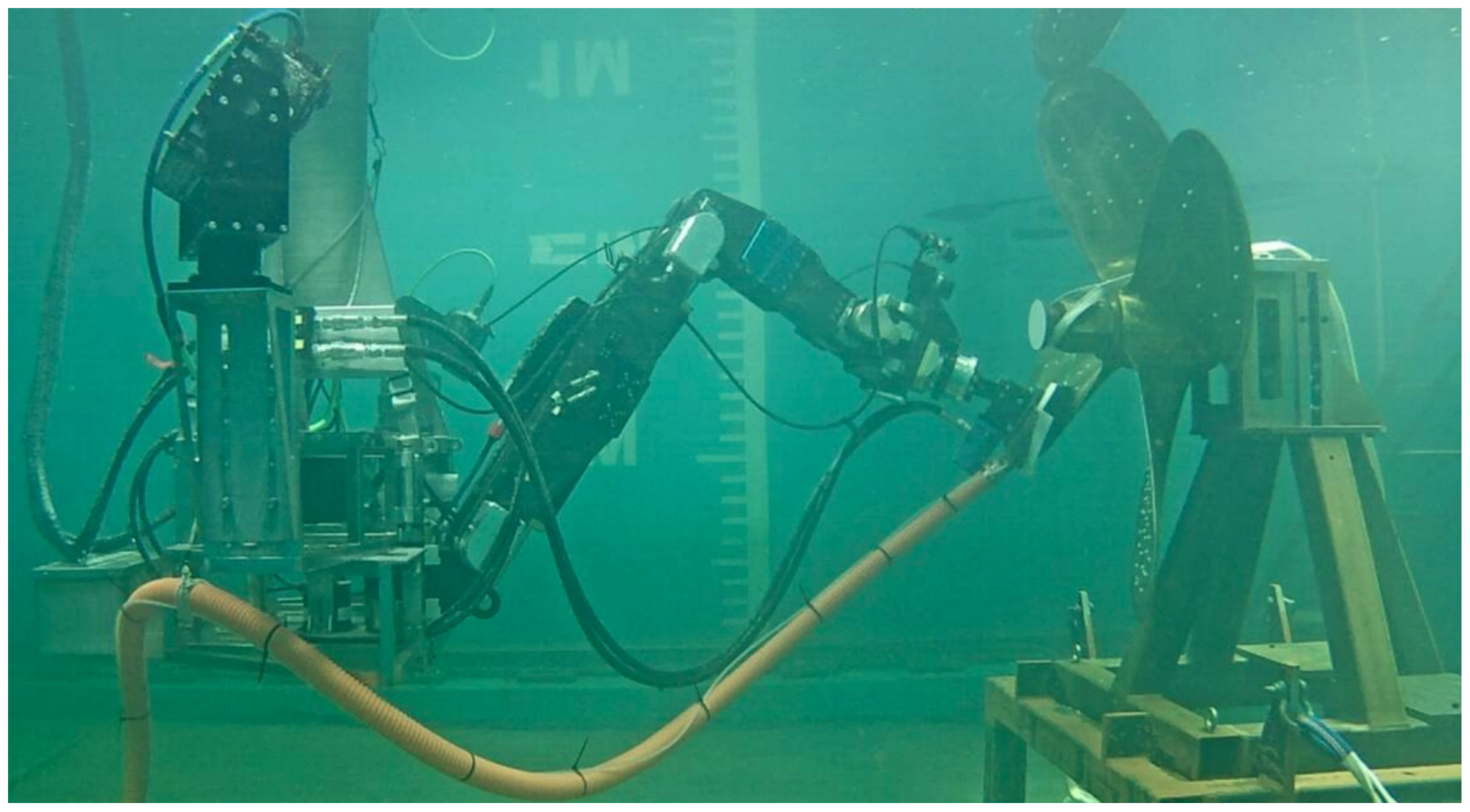
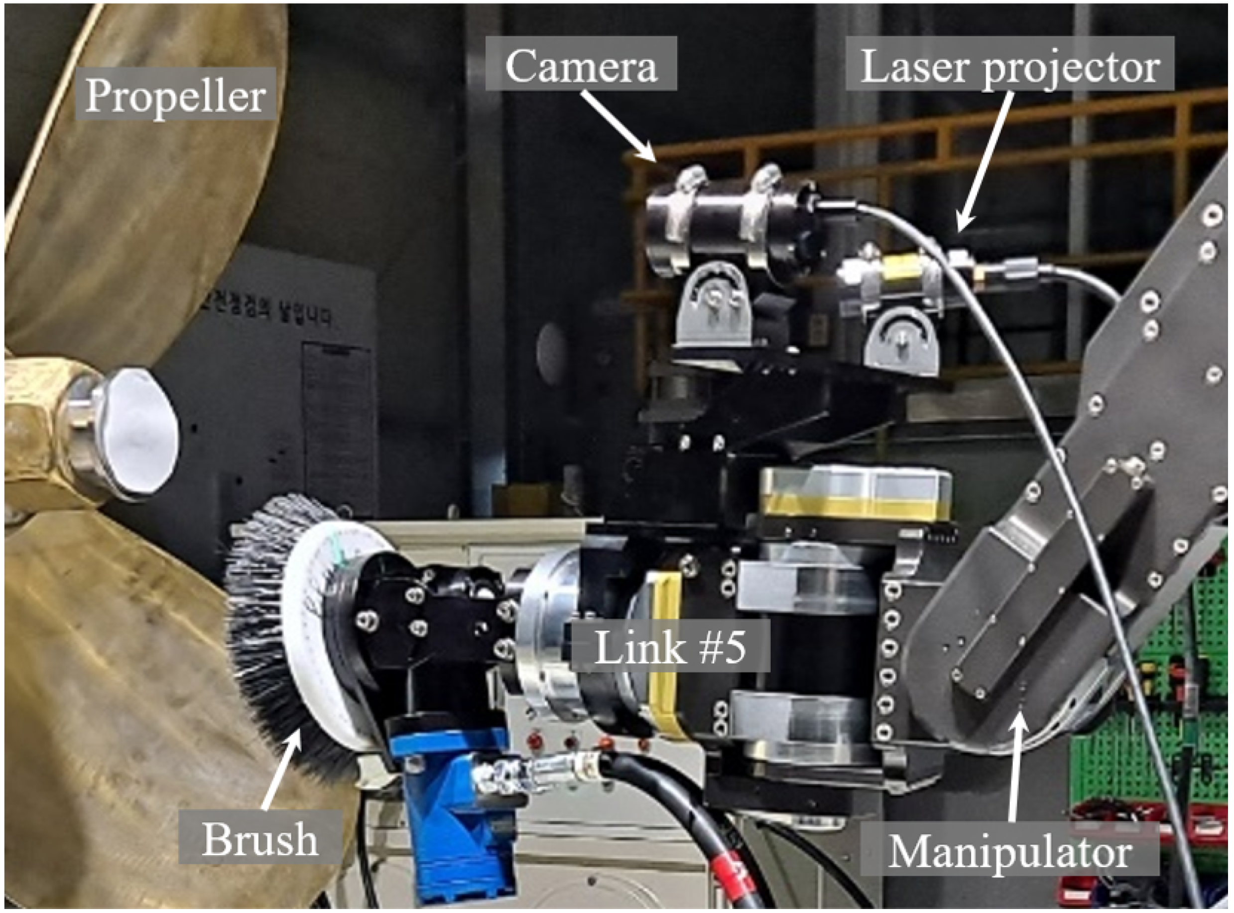
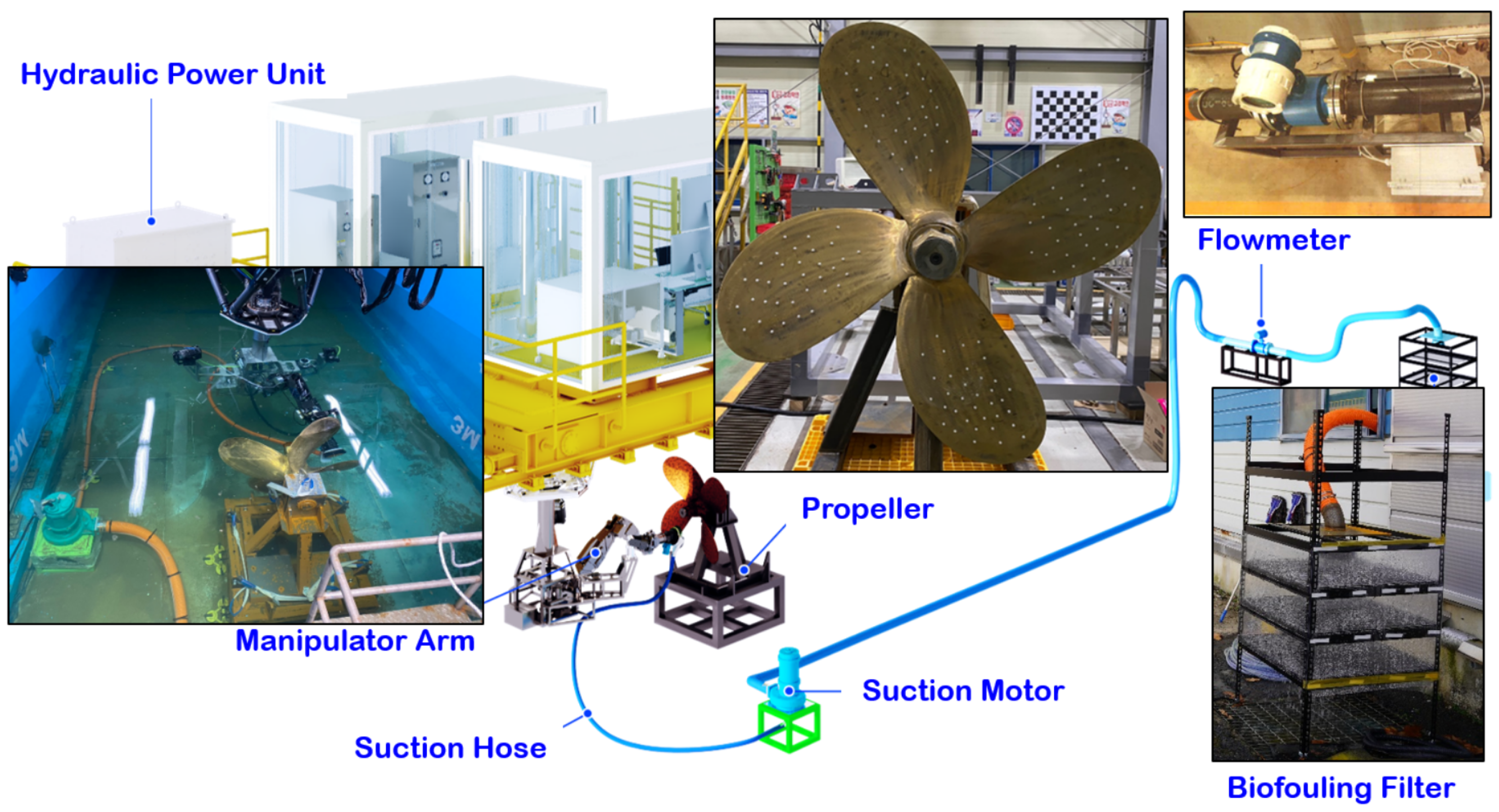
This research presents a robot system that uses a multi-degree-of-freedom hydraulic manipulator for removing the bio-fouling of the niche areas of the hull (
Figure 1). This system was created to be able to approach, with the multi-degree-of-freedom robot arm, areas that were difficult to approach with existing hull cleaning robots. To remove fouling organisms with strong adhesion, a hydraulic operation method that allows for the delivery of significant strength was chosen. Additionally, a laser scanner was installed in the middle of the robot arm so that it could scan the cleaning area according to the movement of the robot arm. Furthermore, a cleaning brush was installed at the end, which was designed to be used to remove and retrieve fouling organisms.
Additionally, various algorithms were applied in this cleaning system for autonomous cleaning. First, the cleaning of the entire autonomous ship hull niche area was divided into the scanning stage, planning stage, and cleaning stage. Then, the recognition of each cleaning area, generation of cleaning paths that cover all cleaning areas, and controlling the hydraulic robot for precise cleaning were designed so that the robot could proceeded autonomously. To select the cleaning area, the point cloud data obtained from the laser scanner were matched with the reference data, and a dynamic simulator and a full coverage path generator were used to extract the valid area for robot arm cleaning. Moreover, the location and positioning of the robot arm cleaning tool were modulated using a velocity controller for precise control of the hydraulic robot to propose an autonomous cleaning system.
Key contributions of this paper can be summarized as follows:
- -
We proposed and developed a novel autonomous cleaning robot based on a multi-degree-of-freedom hydraulic manipulator that can access and clean crevices for cleaning the niche area of a ship: (
Section 3).
- -
In order to develop a fully autonomous cleaning platform, we proposed an autonomous system that can recognize and manage the scanning, planning, and cleaning phases by itself: (
Section 4).
- -
We developed a laser scanner and algorithm that can recognize cleaning zones and autonomously generate fully coverage paths using only scanning information of a part of the target: (
Section 4.1).
- -
We proposed the use of a dynamics simulator in the planning phase to solve singularity problems and collisions with the hull that may occur during cleaning: (
Section 4.2).
- -
We implemented the developed multi-degree-of-freedom manipulator-based autonomous cleaning system in a real tank environment and performed performance verification: (
Section 5).
2. Related Works
The IMO and MEFC continue to set standards for biofouling inspection, removal, and recovery methods to prevent biofouling from disrupting ecosystems, polluting the environment, and reducing ship fuel efficiency. In particular, there are not only problems caused by biofouling growth, but also marine pollution caused by biofouling cleaning and severe effectS on the environment caused by harmful chemical elements (e.g., organotins, tributyltin) in anti-fouling paints [
9]. Therefore, IMO and MEFC are preparing regulations for both biofouling cleaning and recovery [
10]. To this end, an IMO document presented control guidelines for biofouling (2011) [
6], and the correspondence groups were formed and a bio-fouling management plan was presented. They discussed conducting periodic inspections of the ship’s hull and mandatory submission of inspection reports in the IMO sub-committee on pollution prevention and response (PPR9). It was also discussed to enforce proactive cleaning and reactive cleaning based on the fouling rating (FR) of the inspection report [
11,
12]. Proactive cleaning can be performed within 10 µm of antifouling paint damage without bio-recovery obligations when the FR rating is less than 1. Reactive cleaning can be performed between FR ratings 1 and 3 with 10 μm of paint damage, 95% recovery by mass, and 99% recovery of 10 μm organisms. It was discussed that dry dock cleaning should be performed in the case of an FR rating 3 or higher [
11,
12].
In the marine environment, biofouling grows from the micro-fouling stage (e.g., conditioning film, non-adherent bacteria), which is less than 1 mm thick, to the macro-fouling stage (e.g., bacteria, diatoms, macroalgae, larvae of invertebrates and invertebrates), which is more than 1 mm thick, such as diatoms, algae, and larvae [
13,
14,
15]. The U.S. Naval Research Laboratory found that macro-fouling is distributed at 15% after a ship has been in service for 1–2 months, increasing to 61% after 3–5 months, and that the macro-fouling growth stage typically begins after 3 months [
16]. Therefore, proactive cleaning can be performed at 1–2 month intervals, and reactive cleaning is required at intervals longer than 3 months [
1].
The ship-hull-cleaning robot system can be largely classified into hull-attached and floating robots according to the vehicle type, and the cleaning methods can be divided into contact cleaning and a contactless cleaning methods according to the cleaning method [
17].
Hull-attached robots are attached to the flat hull using magnetic wheels or pressure adsorption force, and they clean the biofouling using rotary brushes [
18,
19]. Most of these systems are operated by users through tele-operation. Recently, vehicle positioning and path planning studies have been conducted to develop an autonomous hull-cleaning system. The optical displacement sensor-based position estimation method was proposed for an autonomous hull-cleaning robot [
20], and the optimal waypoint path planning method was proposed to guarantee the shortest travel distance and minimal energy consumption while ensuring the visiting of the robot [
17,
21]. Recently, the underwater ship hull-cleaning robot design by attaching two-manipulator arms to a remotely operated vehicle was proposed and validated in a simulation study [
22].
Floating cleaning robots use a remotely operated vehicle (ROV) with the hull-cleaning devices; these robots can be divided into high-pressure-water cleaning jet and cavitating water cleaning jets, depending on the cleaning methods. These robots can access and clean the flat hull space and niche areas; they do not damage the hull surface owing to the attaching force when they move. However, the pose of a floating robot is hard to maintain owing to the reactive force of the water jet. A significant number of studies on cleaning-tool mechanisms and robot designs have been conducted [
23,
24].
The proposed robotic system can be organized in the form of a robotic arm attached to a hull-attached robot, and the robotic arm can be used to clean nearby niche areas and flat hulls. It is also expected to be installed in a hull cleaning plant organized in the form of a berthing facility to clean the hull of a docked ship. In this study, we propose core technologies for this purpose: autonomous hull sensing and recognition, autonomous path planning, and autonomous cleaning.
3. Hardware Configuration of Niche Area Cleaning Robot
For the autonomous cleaning of the niche areas of the ship hull, a cleaning system was established, as shown in
Figure 1. This system consists of a hydraulic robot arm with six joints (UW3, KnR Systems™), a laser scanner installed in the body of the fifth robot arm, hydraulic one-axis rotational cleaning tool, and fouling organism retrieval device.
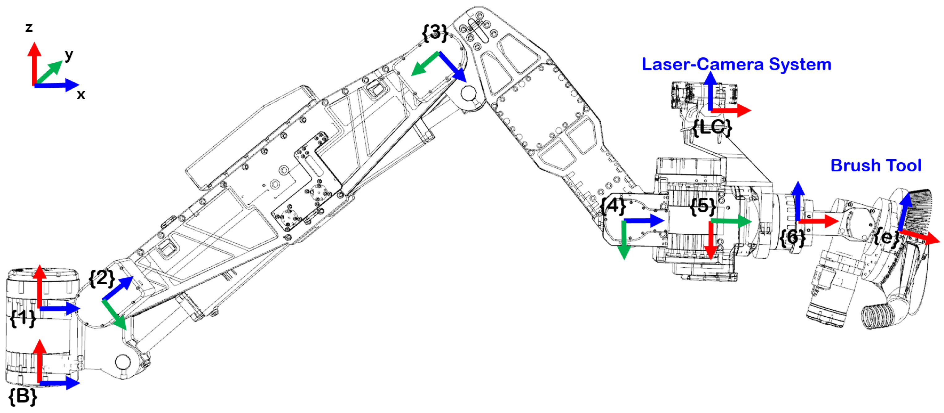
3.1. Six-Degree-of-Freedom Hydraulic-Driven Manipulator Arm
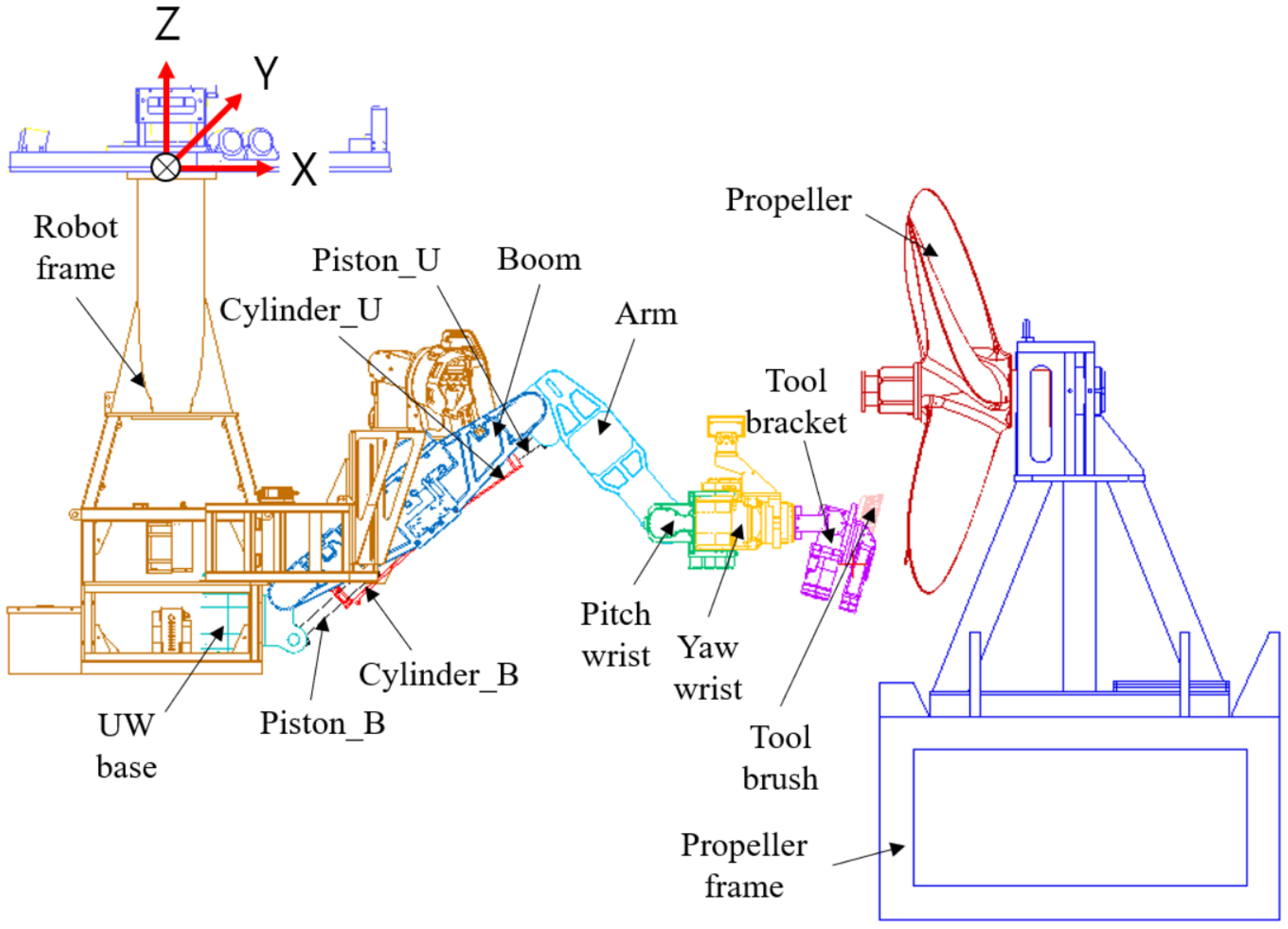
The parts if the six-degree-of-freedom hydraulic robot arm that approaches the niche areas of the ship hull are shown in
Figure 2. This robot arm consists of six links (three pitch joints, two yaw joints, and one roll joint), and the UW3 of the KnR systems was enhanced to fit the workspace of the niche area of the hull. The workspace and payload of this robot arm when stretched to a maximum were 2121 mm and 120 kgf, respectively. The cleaning direction and cleaning tool design proceeded for the niche area of the hull based on the hardware composition of the robot arm.
This robot arm was used to recognize the niche areas of the hull, a laser scanner was installed at the fifth link for cleaning, and a cleaning tool was installed at the end of the sixth shaft. Therefore, the robot had been designed to allow modulation of its scanning path by controlling the location and positioning of the fifth link and to allow for the modulation of its cleaning path by controlling the location and positioning of the end of the robot arm.
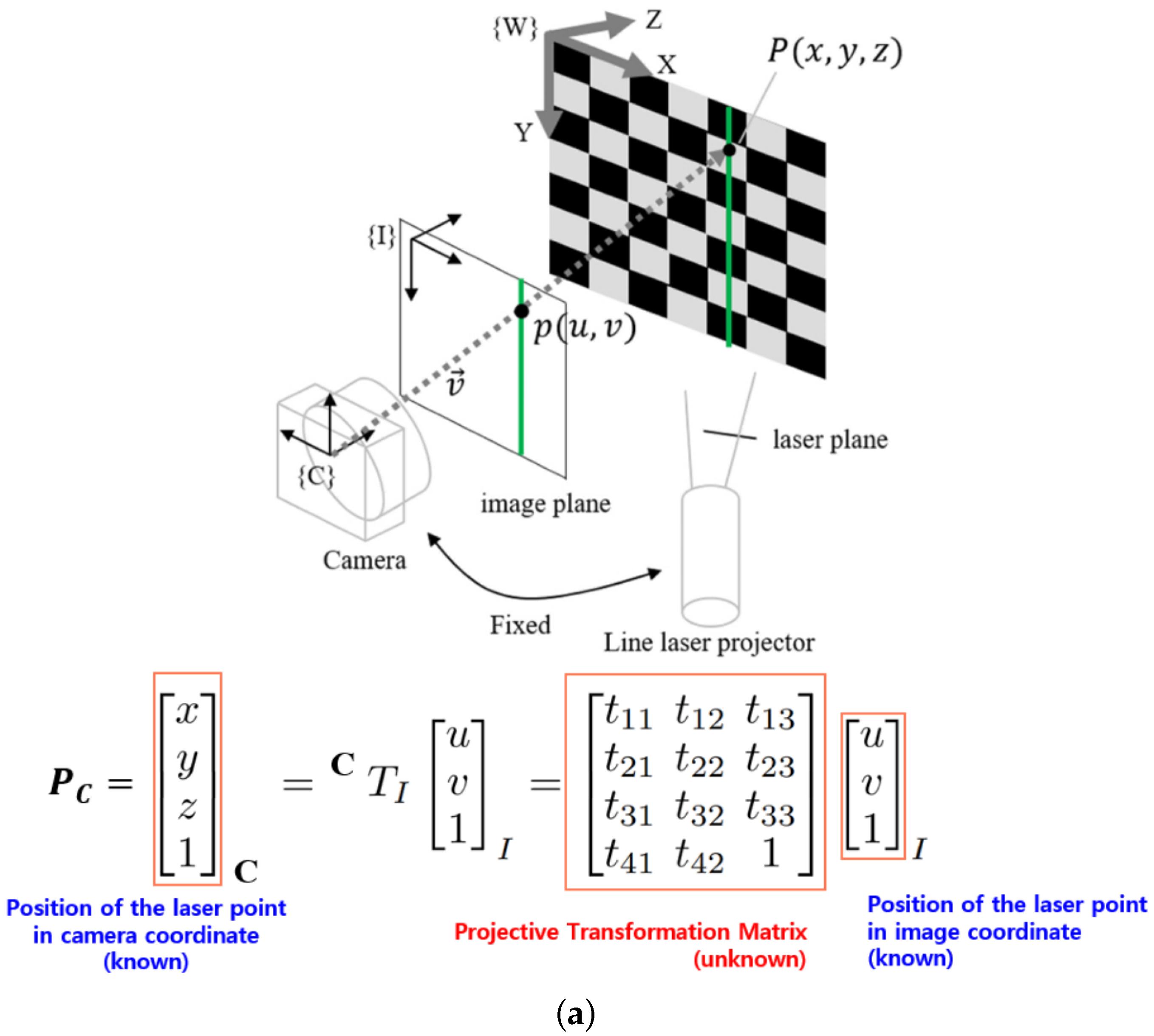
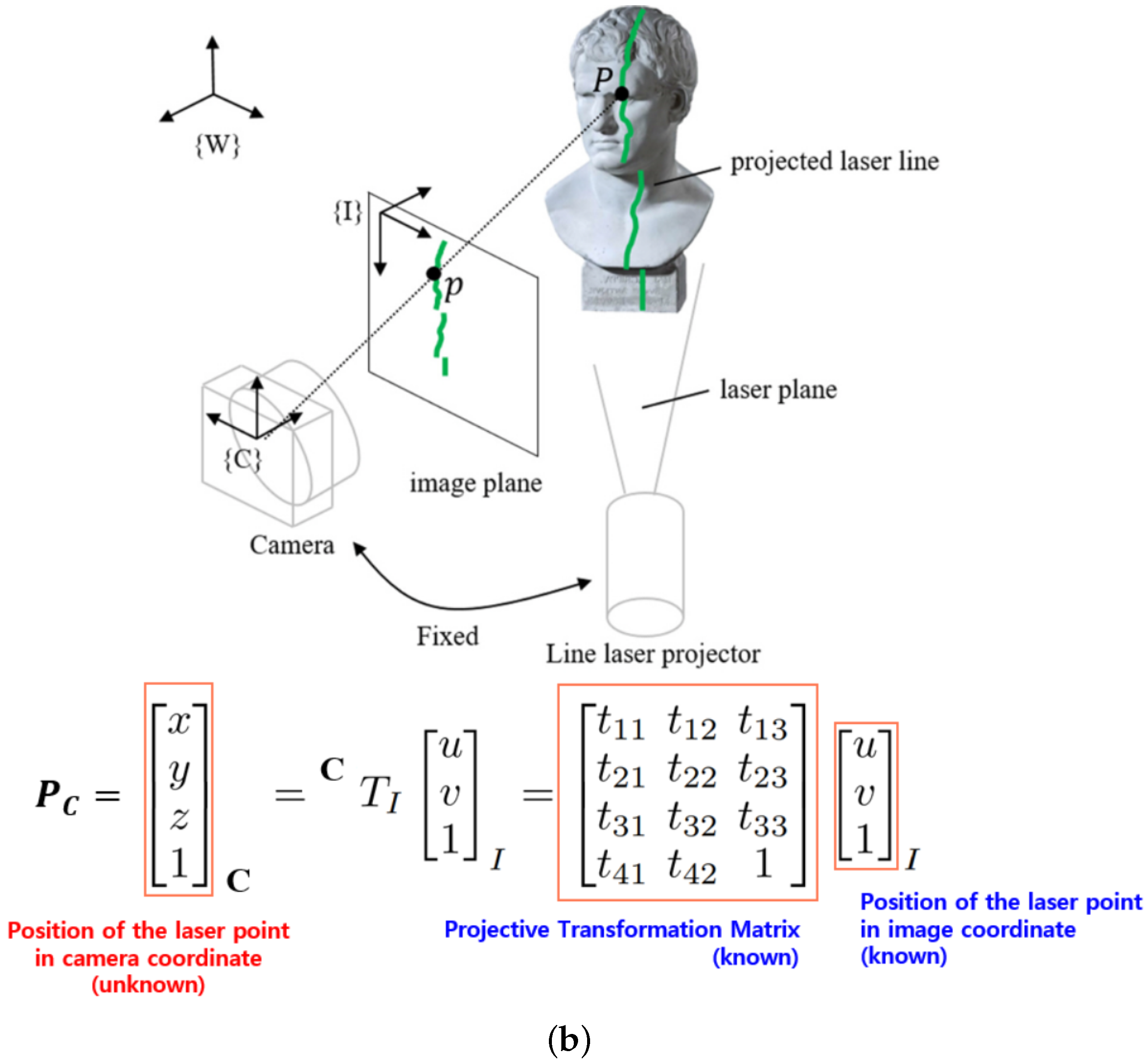
3.2. Underwater Laser Scanner
The underwater laser scanner consists of a laser transmitter and an optical camera (
Figure 3 and
Figure 4). The laser transmitter transmits line lasers in a constant direction, and the optical camera captures the location
of the feature that forms on the target object to estimate this on the two-dimensional image plane
[
25,
26,
27]. To extract the three-dimensional object data based on the features in this manner, a projective transformation matrix
between the image coordinate system and robot coordinate system (or world coordinate) must be derived, and this can be determined in the calibration phase.
The calibration phase is shown in
Figure 3a. When placing the checkboard in front of the underwater laser scanner, we could estimate the location and positioning in the world coordinate through image processing, because the grid size and spacing of the checkerboard are known, and the two-dimensional pixel address of the laser scanner data can be known from the camera image. Thus, the projective transformation matrix that minimizes the error by using these two can be derived. In preliminary experiments, the calibrated laser scanner had a mean error of 2.87 mm at a distance of about 1.4 m (
= 4.35 mm).
To acquire reliable point cloud data from a relatively broader area, the underwater laser scanner was fixed to the fifth link of the hydraulic robot arm (
Figure 2). Furthermore, the calibration phase occurred underwater, as shown in
Figure 3a, to determine the projective transformation matrix of the composed environment [
28]. In addition, the scanning path of the robot arm was programmed to move through the lawnmower path to extract the data from the broad niche cleaning area using the two-dimensional line laser. The point cloud data obtained here were reconstructed.
3.3. Brush Tool and Recovery System
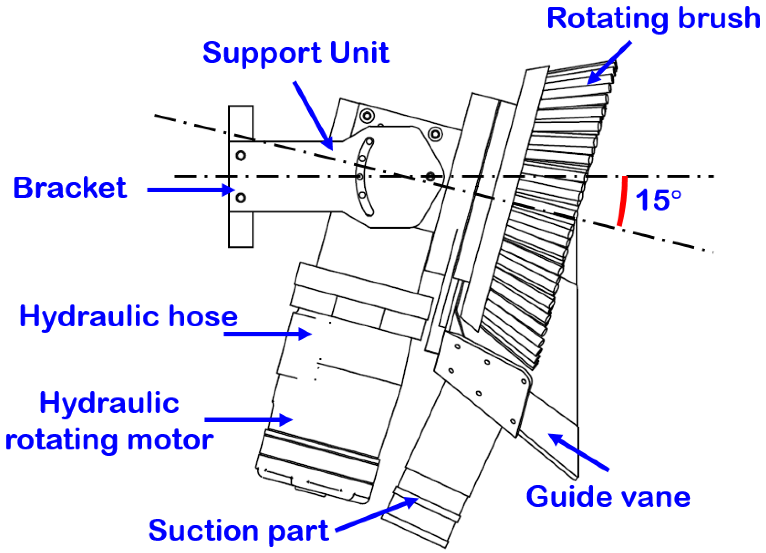
For direct cleaning of the fouling organisms, a cleaning device that includes an elastic cleaning brush was installed at the end of the robot arm. The cleaning device rotates because it is directly connected to the rotating hydraulic motor, and it separates the fouling organisms from the ship by force. Additionally, the retrieval device installed at the bottom of the cleaning device was designed to collect the fouling organisms that fell using an external absorption motor.
To determine the optimal brush strength, length, and motor rotating velocity, and to design the retrieval device, analyses were performed using computational fluid dynamics (CFD). Consequently, the cleaning brush was installed at a 15
inclination, and only certain parts of the brush were designed to make contact with the cleaning area to concentrate the cleaning intensity. Furthermore, the guide vane was formed at the bottom for collection (
Figure 5).
3.4. Robot Body
The robot body was connected to the six-axis motion platform at the top of the water tank, and the motion platform was connected to the towing carriage and fixed. The six-axis motion platform was designed so that it could change the location and positioning of the robot, and implement the six-degrees-of-freedom motion. A multi-beam echo sounder was installed onto the robot body to enable the recognition of the surrounding topography, among others, near the ship, and a hydraulic compensator was installed to compensate for the water pressure depending on the depth of the robot. In particular, this was used to recognize the approximate location of the niche area, and the laser scanning path was planned and controlled based on these data to obtain the relative location and positioning of the robot and the niche area (
Section 4.3).
4. Autonomous Niche Area Cleaning System
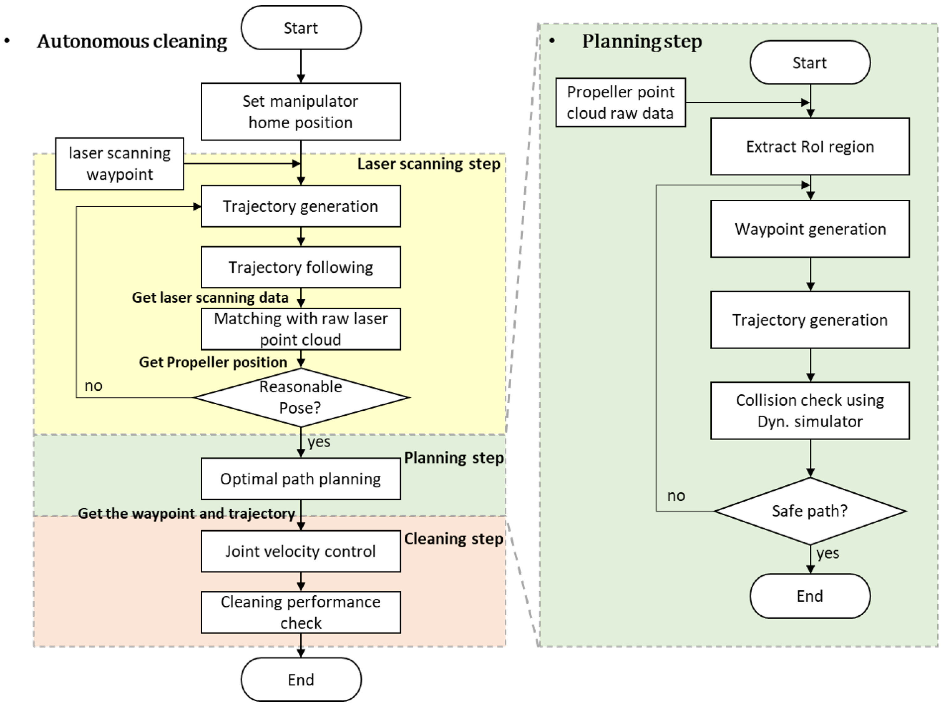
The algorithm flowchart for ship hull cleaning is shown in
Figure 6. For this robot, the stages of cleaning were distinguished into the scanning, path planning, and cleaning stages. Furthermore, the recognition of each cleaning area, the generation of cleaning paths that could cover all cleaning areas, and hydraulic robot control for crevice cleaningwere designed to proceed autonomously.
The laser scanning stage was composed of point cloud scanning, point cloud data and reference data matching, and relative distance estimation processes. First, the laser scanner installed at the fifth link of the robot arm was used to scan the entire or a part of the cleaning area. Here, to obtain a point cloud that is uniform over a broad area, the positioning of the fifth link was maintained to set the scanning path as the lawnmowing path, and this setting was run. The path point here was arbitrarily set up based on the scope of the underwater laser scanner’s scanning and the resolution. Later, the point cloud data gained from the laser scanner were matched with the reference data using the iterative closest point (ICP) algorithm. When the matching error converged to a certain level or below, the image location value obtained from the scanner and the laser scanner location value was used to acquire the positioning value and the relative distance between the point cloud and the robot (detailed in
Section 4.2).
In the path planning stage, region of interest (ROI) extraction, full coverage path generation, and re-setting of the cleaning path based on the dynamic simulator proceeded. First, the ROI was set to define the niche area among the point cloud data obtained in the laser scanning stage. Here, the depth value between the point cloud data and ROI as a reference was used for the differentiation. To clean all areas within the ROI, the full coverage path planning was performed considering the cleaning direction. Later, the dynamic simulator was used to verify whether the area could be cleaned and for any collisions with the robot arm body. Then, the cleaning path planning that removes problematic areas was established (detailed in
Section 4.3).
In the cleaning stage, the location of the end of the robot arm was controlled to run the cleaning path established during the path planning stage. The velocity of the six joints was controlled to modulate the end of the hydraulic robot arm, and the geometric Jacobian matrix was used to calculate the velocity of the joint for controlling the target location of the robot end. To correct the control errors, a proportional-integral (PI) controller was designed. Additionally, the singular value decomposition (SVD) was calculated together at every moment during the inverse kinematics calculation to resolve issues of singularity, control input divergence, etc., that could arise during the control. Furthermore, the control was set up to stop when a singular value equal to or below a certain value was derived (detailed in
Section 4.4).
4.1. Location and Positioning Estimation between the Robot and Niche Area Using Point Cloud Data
While the laser scanner introduced in
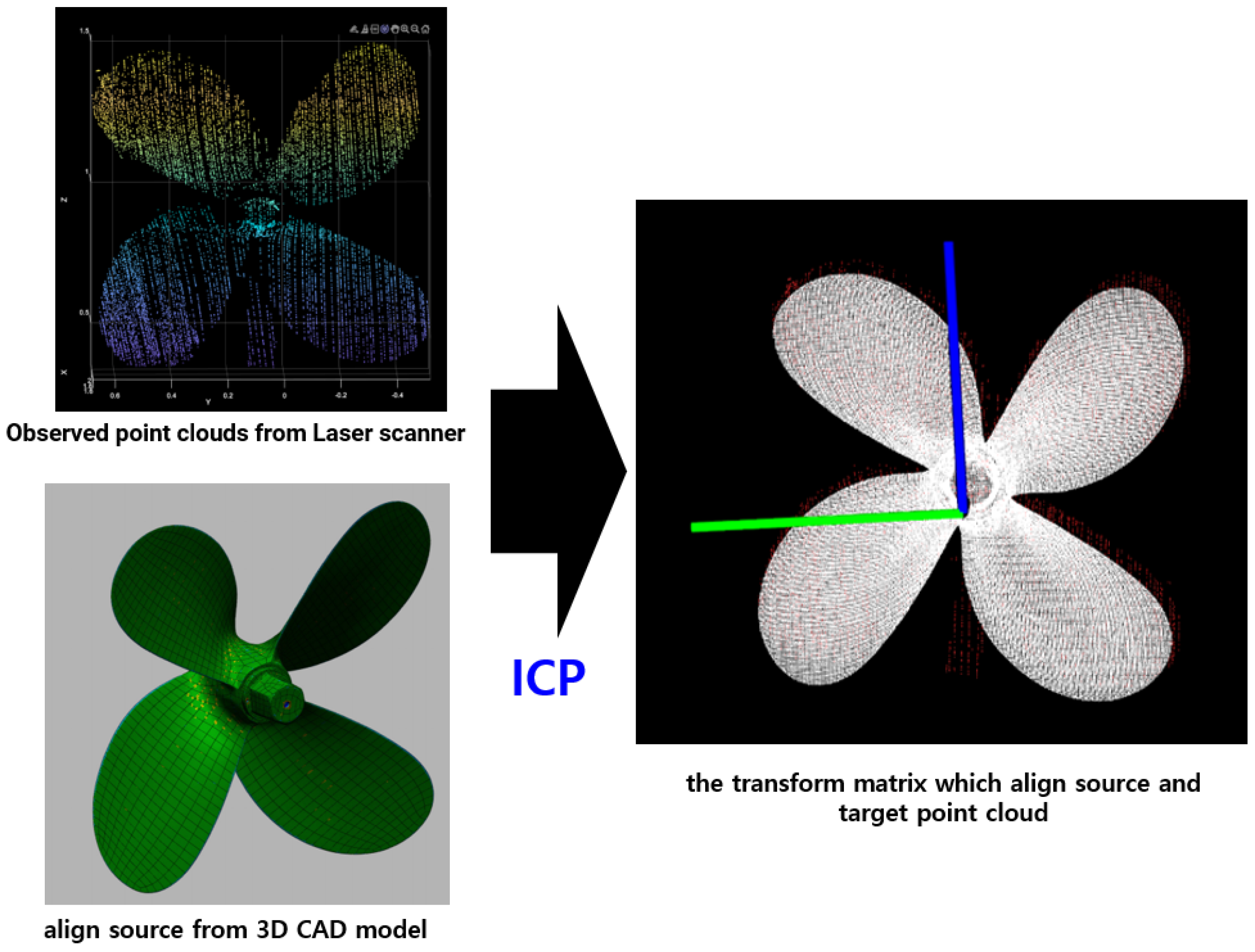
Section 3.2 scans with the lawnmower path, the point cloud could only be acquired for the center point of the robot arm scanning and for certain areas or the entire area depending on the relative distance. In particular, while generating the scanning path of the robot arm, the scanning range could be rapidly reduced depending on the surrounding objects or the structure, so the niche cleaning area data could only be obtained through partial scanning data. To overcome this problem, matching was performed between the sensor data obtained using the laser scanner and the existing precise 3D computer-aided design (CAD) model. Here, the precise 3D CAD model could be obtained through the manufacturing blueprint or scanning during dry docking.
Matching between the point cloud data obtained from the laser scanner and the precise 3D CAD model was performed through the ICP algorithm [
29]. ICP is an algorithm that repeatedly performs transformation, translation, and rotation to seek the minimum Euclidean distance between two point cloud datasets. The distance was determined through the following equation.
This algorithm determines the aligned matrix that has the minimum Euclidean distance between the point cloud data obtained from the laser scanner and the precise 3D CAD model (
Figure 7). Here, the align function obtained was used to estimate the correlation between the point cloud data and CAD model, and when this is used with the homogeneous transformation matrix from
Section 3.2, the location and positioning between the robot body and niche area can be estimated (
Section 5.2). However, in case the point cloud data obtained from the laser scanner are significantly small and only represent the local minimum or the number of barnacles is high and the niche area shape is deformed, the ICP matching error becomes significant. In these cases, the point cloud and CAD model may not match well. To prevent this, the scanning path was reset, and the point cloud data were obtained again when the ICP error value resulted in a certain value or above.
4.2. ROI Extraction and Optimal Cleaning Path Generation
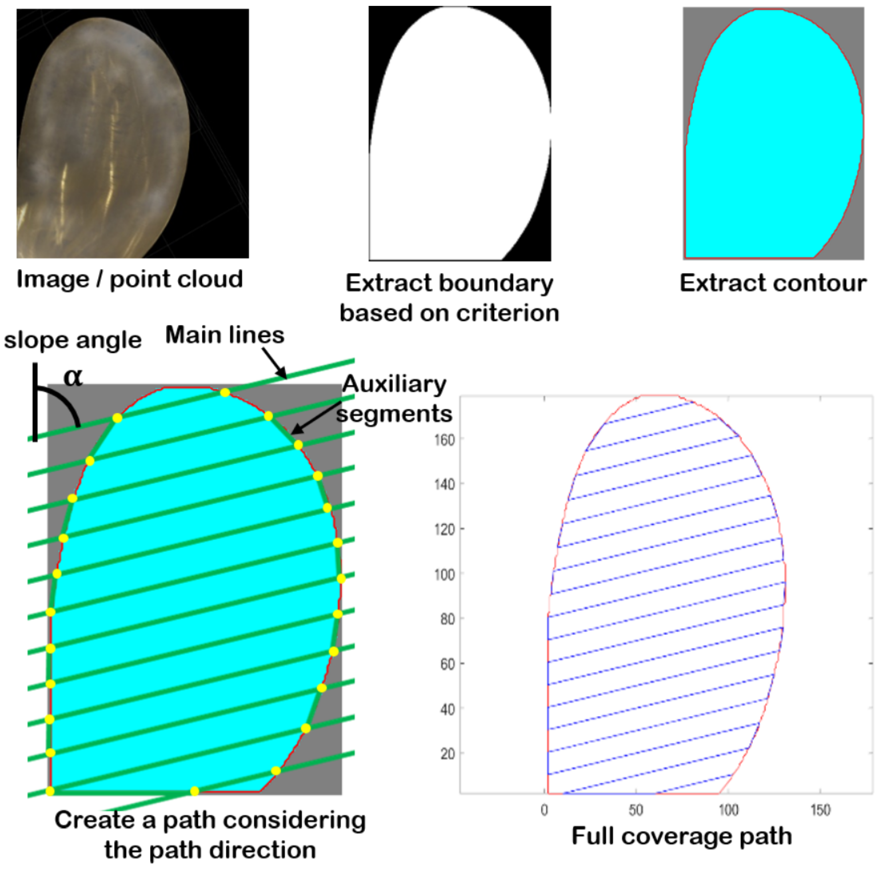
To set the cleaning area, the ROI of the hull and other data must be distinguished from the point cloud. In general, the red, green, and blue (RGB) data, feature data, or depth data obtained from the laser scanner could be used as boundary data for distinguishing the ROI. In this algorithm, the matched three-dimensional CAD point cloud data were projected onto the YZ plane, and the X-axis data were used as the depth data to extract the boundary data. The boundary that the depth data of the point cloud belonged to that corresponded to the niche area was set as the boundary contour based on the three-dimensional CAD data and scanning data, and the area within this contour was designated as the ROI [
30,
31].
Then, a full coverage path generator that could clean inside the ROI was developed. The tool that we used had a 15
inclination in the direction of the pitch so that the cleaning area and cleaning efficiency could be adjusted according to the cleaning direction (
Figure 5). Therefore, the cleaning path had to be set up in the top-to-bottom direction so that the cleaning tool that we designed would clean optimally. For this purpose, full coverage path generation that could account for the cleaning direction was performed (
Figure 8) [
32]. To consider the degree of freedom of the robot arm described in
Section 3.1 and the brush characteristics discussed in
Section 3.3, the main line angle was set to 0
, and the distance between the main lines was set based on the area of contact of the cleaning brush. Furthermore, the auxiliary segment that connects the main line was set as a movement section where no cleaning was performed, and it was generated as a path point for moving to the next main line.
Later, the three-dimensional six-degree-of-freedom cleaning brush path point (
) was extracted from the
ith path point (
) as follows within the ROI that was projected onto the YZ plane.
Here,
is the closest point cloud data element from the two-dimensional path point
, and
is the normal vector value of
. Additionally, the trajectory planner was determined according to time using the cubic polynomial method for the regional path between the current path point
and target path point
. The desired position
and desired velocity
at time t obtained through this was used in the robot arm velocity controller to generate control input for the robot arm end at the task space [
33].
However, the robot arm could not always follow the path point generated by the trajectory planner and the regional path. An inappropriate target velocity and inability to estimate the location of the target could arise owing to the workspace and singularity that the robot arm has, and collision could occur between obstacles and the link depending on the robot arm’s movement in complex spaces. To resolve this issue, the kinematic constraints of the robot arm and collision with the surrounding environment were autonomously considered using a dynamic simulator before the cleaning stage. By autonomously revising the input as path points and regional paths that can be cleaned after determining the availability of the robot for cleaning and collision possibility based on the current environment data in the dynamic simulator, the matched niche area data, and control input data of each robot arm joint, the issues that may occur during cleaning were minimized (
Section 4.3).
4.3. Collision Check and Non-Collision Path Planning with Dynamic Simulation
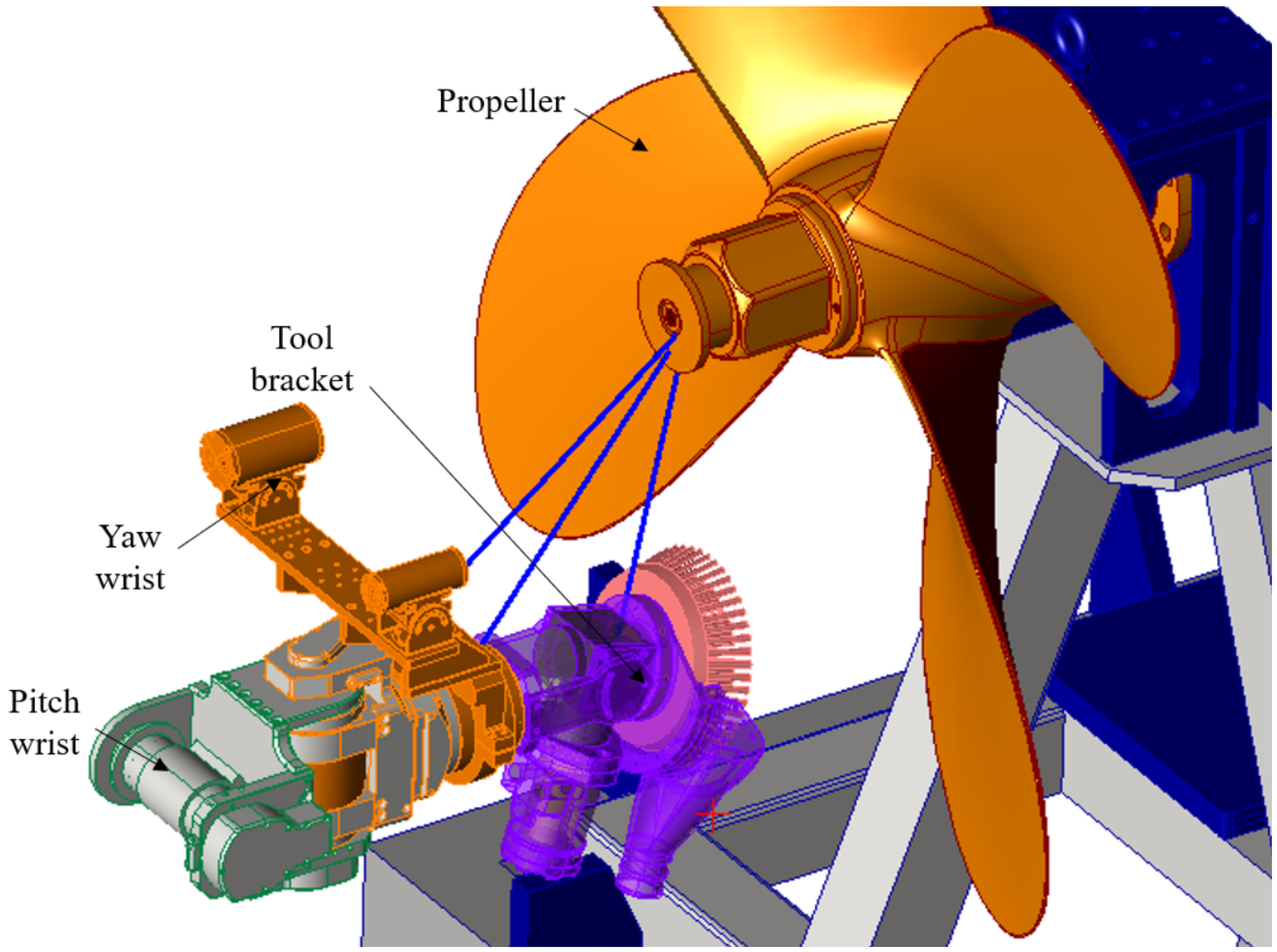
To determine the full coverage path planning, the collision detection contact between the brush tool frame and propeller of the ship hull was simulated. A dynamic model for a cleaning robot system was developed using DAFUL software based on a multibody dynamics formulation (DAFUL, ANSYS Motion™). The dynamic model proposed a rigid-body cleaning robot dynamics model, rigid-to-rigid-body contact model, and their control algorithm. They then employed integration for co-simulation with DAFUL and MATLAB Simulink software. The developed dynamics model comprised a robot frame, 6-DOF manipulator, and propeller, as shown in
Figure 9. It can consider 14 bodies, 14 joints, and one force element.
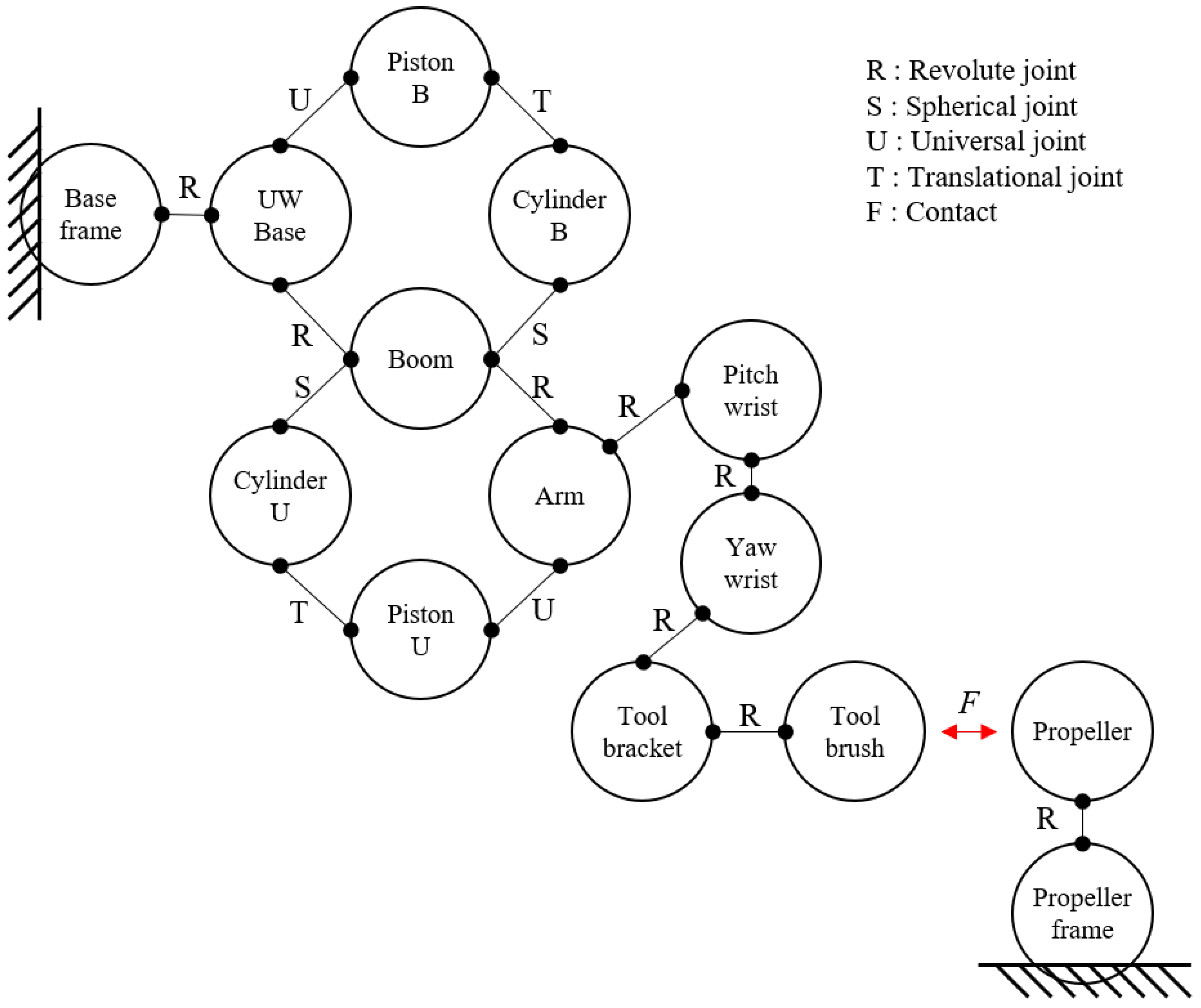
Figure 10 shows the definition of the topology of the cleaning robot system with respect to the relationship between each body; where, “R”, “S”, “U”, and “T” indicate revolute, spherical, universal, and translation joints, respectively. Furthermore, “F” denotes the force element owing to the contact between the tool brush and propeller bodies, and that between the base frame and propeller. Consequently, the dynamic model of the cleaning robot system has eight DOF.
Table 1 and
Table 2 list the properties of the body and joint elements. The body’s parameter represents the mass and inertia tensor on a three-dimensional plane. Joint type as well as relationship of inner and outer body are represented based on multibody kinematics. Here, we consider the principal moment of inertia with respect to the inertial reference frame in
Figure 9, and affect to the joint friction and underwater drag force regard as zero.
To detect the joint angles of the manipulator when each body experiences a collision, penetration using the Hertz contact model was examined [
34]. In the rigid-to-rigid-body contact model using the DAFUL software, the two contact surfaces of the bodies must be determined. Therefore, pitch wrist, yaw wrist, and tool bracket bodies that can collide with the propeller body may be chosen. The Hertz contact model is expressed in Equation (
4). Here,
is the penetration between two bodies,
and
are spring and damping coefficients, with values of 0.01 N/m and 0.01 N/m/s, respectively. The parameter values were small because the contact force was not considered, whereas the penetration and joint angles when generating collisions were considered (
Figure 11).
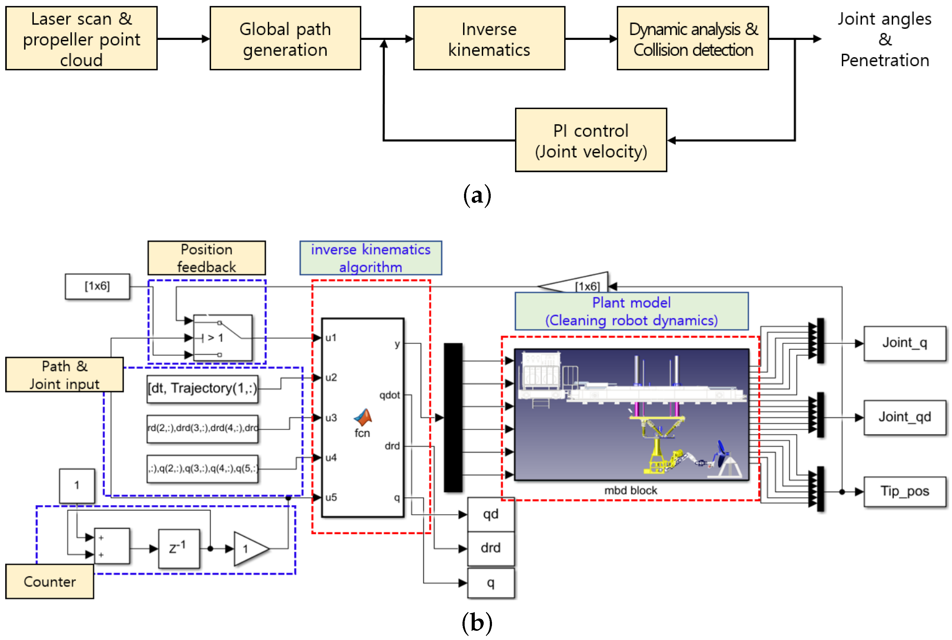
The entire simulation process of the developed co-simulation model is illustrated in
Figure 12a. First, the propeller depth was obtained as point cloud data using an underwater laser scanner. Subsequently, the global trajectory was generated using a path planning algorithm [
32]. Here, the perpendicularity between the tool brush surface and propeller blade surface was maintained as a constraint. Therefore, by applying the initial position, path, and desired velocity to the inverse kinematics algorithm with a cleaning robot system, the global position was transformed into local joint angles and angular velocities. Then, the plant model of the cleaning robot system was moved to each position and attitude, and the penetration was verified using the contact model. The feedback loop was designed for the pi-controller to fix the position error. An environment of co-simulation was developed and integrated in the MATLAB software, as shown in
Figure 12b [
35]. This study considered only the right-down blade of the propeller and performed global path planning.
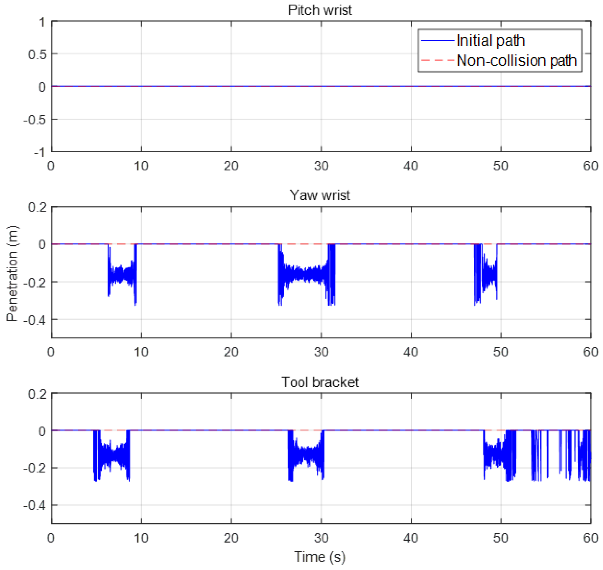
The simulation results indicate that the penetration proceeded to the yaw wrist and tool bracket bodies at 8–10, 25–32, and 48–60 s, as shown by the blue line in
Figure 13. However, the pitch wrist body did not make contact with the propeller. In addition, the amplitude of the detected penetration was less than 0.3 mm.
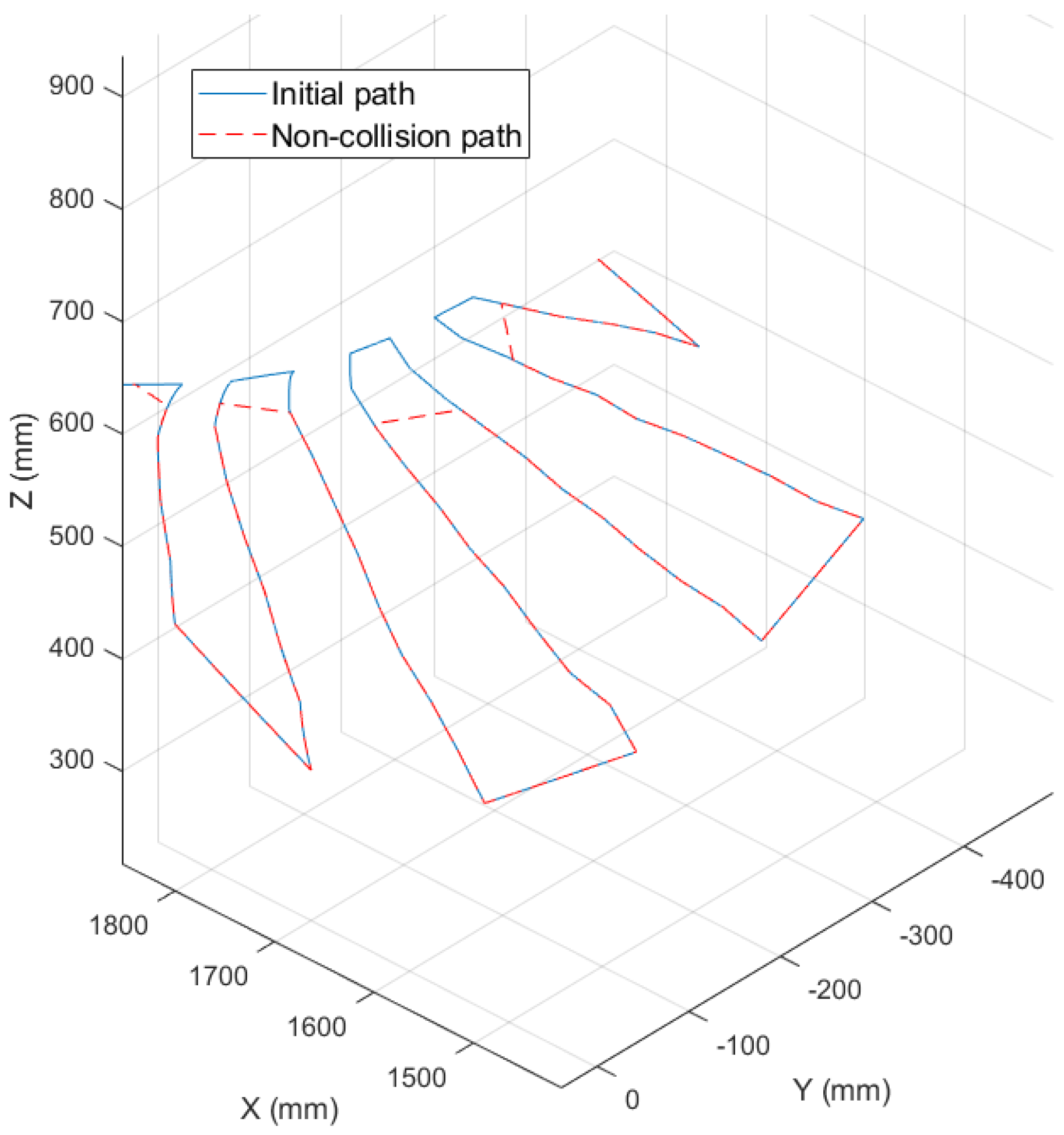
Using these results, the global trajectory was re-generated without collision with the propeller, as shown in
Figure 14. Here, the blue line indicates the initial global path, and the red dotted line indicates the modified non-collision global path obtained using the proposed detection algorithm. In this case, the modified path covered approximately 85% of the propeller blade. Due to the fact that the perpendicularity of the tool brush to the propeller blade was set as a constraint, the cleaning coverage can be low. Finally, when the non-collision global path was applied as the input data, collision did not occur in the propeller body, as indicated by the red dotted line in
Figure 13. Therefore, the proposed method can be used to detect and avoid propeller collisions during the operation of the cleaning robot system.
4.4. Velocity Controller Development Using the Geometric Jacobian
4.4.1. Geometric Jacobian Matrix Derivation
The geometric Jacobian matrix is generally used to mathematically express the relationship between the joint space and workspace. This is induced to define the relationship between the joint velocity and robot arm end-effector twist using geometrical data [
36]. The geometric Jacobian matrix can be expressed as follows:
Here,
is a 3 × 1 matrix that denotes the partial differential relationship equation for the
ith position.
is a 3 × 1 matrix that denotes the partial differential relationship equation for the
ith orientation. The robot arm that we used had a total of six joints; therefore, a relationship equation for six joints was derived.
was represented as a 6 × 6 matrix. Here,
and
can be determined as follows.
where
P and
indicate the location of the end of one robot arm and the location of each joint, respectively, based on the basic coordinate system.
can be derived at the first three elements of the fourth column of the transformation matrix
. Additionally,
is the joint axis vector of each joint, and it can be expressed as follows:
where
refers to the rotation matrix from joint
a to joint
b,
i is the joint number, and
=
0
. As such, the geometrical information of the robot arm can be used to derive the Jacobian matrix. This can be used to determine the necessary joint velocity based on the target velocity in the work space.
4.4.2. Joint Velocity Controller
As determined in
Section 4.4.1, the joint velocity
in the joint space for reaching the robot arm end linear velocity of
and angular velocity
in the workspace can be determined through the Jacobian matrix as follows.
Thus, the input joint velocity can be referred to as the Jacobian matrix relationship equation according to the target linear velocity, angular velocity, and current joint angle
q. When controlling the PI for the joint velocity input, the input u for the target joint velocity
can be expressed as follows.
Here, e is the control error, and and are the proportional gain and integral gain, respectively.
4.4.3. Control Stability Verification Using SVD and Prevention of Malfunctioning
The geometric Jacobian matrix-based controller developed in
Section 4.4.2 could cause the issue of singularity. This implies that the Jacobian matrix becomes unstable by losing its rank. In this case, the robot arm may either not have a solution to the target joint velocity
for determining the target linear velocity of the robot arm end
and the angular velocity
or have an inappropriate solution that exceeds the performance of the actuator of the robot arm. This singularity issue could induce an erroneous control input into the robot arm or damage the target object. Thus, singular value decomposition (SVD) analysis was used to prevent the issue of singularity that could occur during robot arm operation.
SVD is one of the methods that can be used to disintegrate a matrix into an orthogonal matrix and a diagonal matrix. The Jacobian matrix and inversed Jacobian matrix can be disintegrated as follows.
Here, if the Jacobian matrix is referred to as the
m ×
n matrix,
U is the
m ×
m matrix,
V is the
n ×
n matrix, and
the diagonal matrix of
m ×
n that has the singular value
as the diagonal component. The Jacobian matrix that we used was 6 × 6, so
m =
n = 6. Here,
and
in detail are as follows, where
.
Here, if the singular value approaches zero, in the inversed Jacobian matrix approaches infinity. This indicates that the target joint velocity for running the target robot arm end linear velocity and angular velocity is excessively large. To prevent this, a value that suits the threshold value of the robot actuator was set, and this was continuously verified during the operation of the robot. If a singular value of a certain value or below was determined, singularity occurrence was assumed to stop the operation.
5. Experiment
The most significant factors affecting the removal of fouling organisms by the autonomous cleaning robot are the accessibility of the niche areas of the hull, the cleaning rate of the fouling organisms, and the retrieval rate of the removed fouling organisms. To verify the performance of the proposed autonomous cleaning robot of the niche areas of the hull, an experimental environment was formed. The robot autonomously recognized the niche areas of the ship hull in this environment, generated the path points that can be cleaned, and followed the regional path to perform cleaning. This experiment was performed repeatedly in various environments to validate the cleaning performance of the robot and the retrieval rate of the fouling organisms.
5.1. Environment
For the validation of the experiment, an autonomous niche area cleaning robot and niche areas of the ship hull were simulated in an engineered tank environment, as shown in
Figure 15. The water level of the tank was set to 2.5 m, and the robot body was fixed to the towing carriage. As the cleaning target, a four-blade propeller (diameter = 1.3 m) was selected as one of the most representative niche areas of the hull. Propellers have complex shapes that include curved surfaces and are usually fabricated with materials such as brass to which antifouling paint cannot be applied; thus, they are a niche area for which it is difficult to manage fouling organisms. To simulate the fouling organisms that are most difficult to clean, 20–30 clams with a size of 1 cm
were attached onto four sides of the propeller, and a strong double-sided adhesive foam tape was used to simulate the adhesive strength of the fouling organism. In addition, a suction motor at the bottom of the cleaning brush and a retrieval device of fouling organisms were connected for the collection of fouling organisms of the hull cleaning robot. Furthermore, a flow meter and flow regulator were used to identify the flow rate of the retrieval device.
The experiment was repeated six times based on the algorithm flowchart presented in
Figure 6. Considering the workspace of the robot arm, single-blade cleaning proceeded for each experiment, and the propeller angle was arbitrarily changed in each experiment so that autonomous cleaning could be performed. Here, the cleaning rate and retrieval rate were assessed in each experiment based on the number of fouling organisms.
5.2. Scanning and Planning Results
For the laser scanning and planning stages, point cloud data scanning, matching between point cloud data and reference data, estimation of the relative distance value, generation of the valid path, and verification were performed.
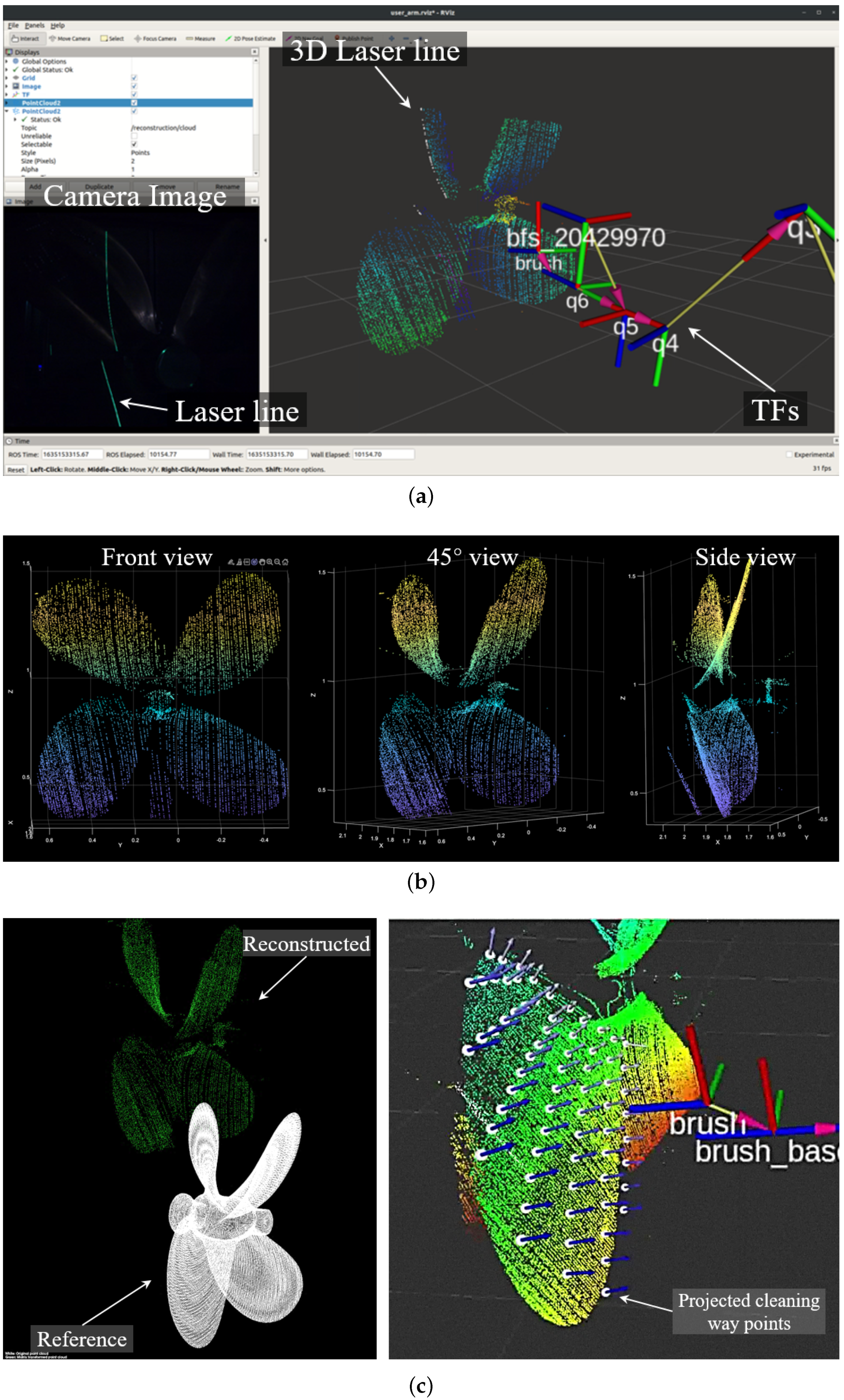
Assuming that the approximate information of the target niche area of the hull was obtained through a sonar sensor, among others, the location and positioning control of the fifth axis of the manipulator proceeded based on the center point to move through the lawnmower path. The results from this process are shown in
Figure 16. The left image presents the laser line obtained from the coordinate system of the camera, from which one line of point cloud data is gained. Furthermore, the results of the accumulated line laser obtained according to the movement of the robot arm are shown on the right of
Figure 16a. The final laser scan-based point cloud data are shown in
Figure 16b.
Later, ICP matching between the precise three-dimensional CAD data and the obtained point cloud data was performed. The green point cloud data on the left of
Figure 16c are the data obtained from the laser scanner, and the white data below are the CAD model data. After acquiring the correlation between these two datasets, a full coverage path plan was established as shown on the right of
Figure 16c. Here, path points that only include valid paths were created to estimate the path. The three-dimensional path point was expanded using Equation (
3) based on the two-dimensional path point, and the trajectory planner was used to generate the regional path between the path points. Consequently, the control input for the robot arm end was generated using the acquired regional path.
5.3. Control Results
The scanning control results and cleaning control results of the propeller are shown in
Figure 17 and
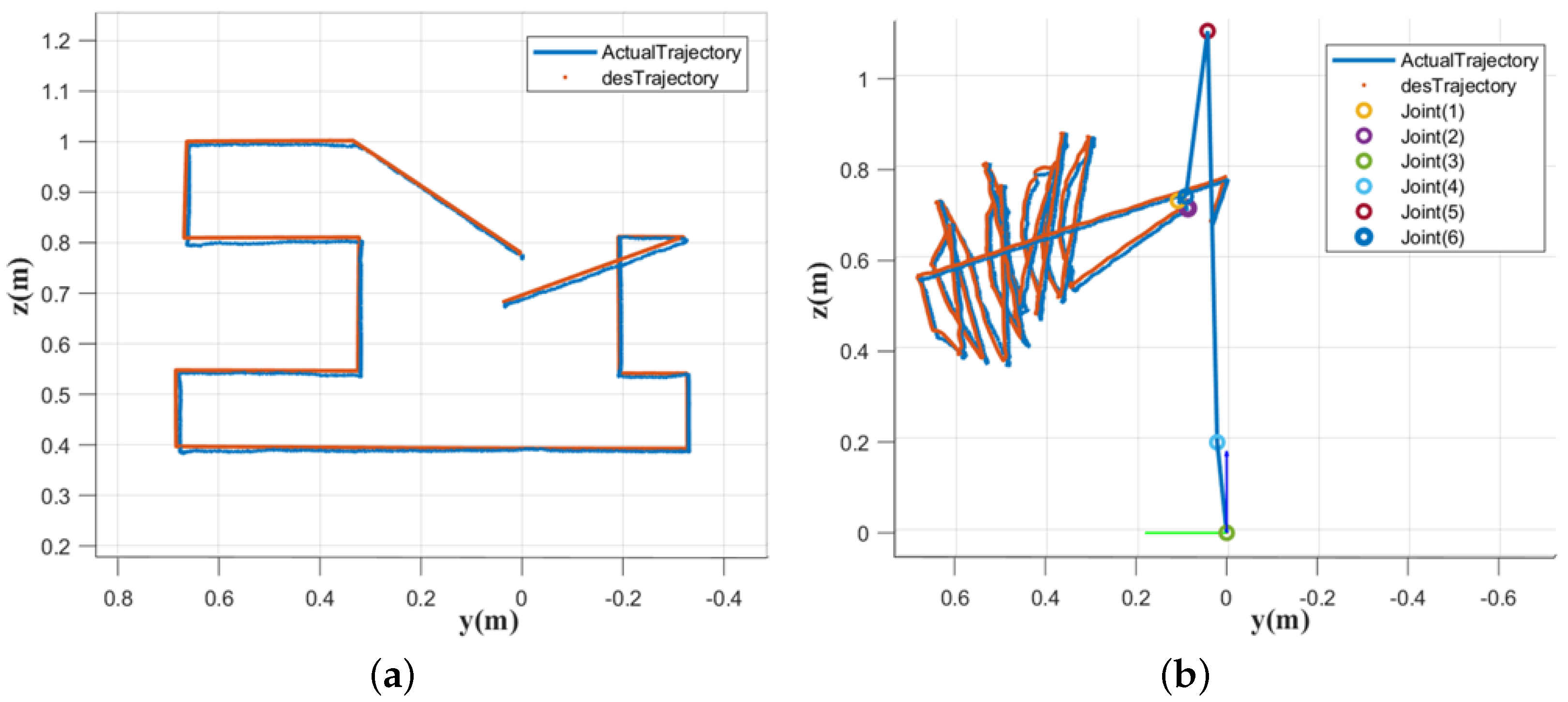
Figure 18. When estimating the scanning path and control, scanning was performed for the YZ plane as shown in
Figure 18a to maximize the use of the robot arm work space. To prevent collision with the propeller shaft, the central area was removed from the scanning area. The scanning waypoints had a mowing pattern and were designed to move up-down-up; a total of 14 waypoints were created. In the scanning phase, no interaction occurred between the robot and the target cleaning area; therefore, control was performed without significant disturbances and errors. Furthermore, the robot yielded an average scanning trajectory control error of 3.2 mm.
The trajectory-following results from the cleaning stage are shown in
Figure 18b. In the cleaning stage, the cleaning brush equipped at the end of the robot arm cleans by directly making contact with the niche area of the hull; as a result, the path control error was inevitably greater than with scanning control. In addition, the problem of inconsistent distances occurred between the cleaning brush and the cleaning target at some points. However, the path estimation control error at these points was not significant. This was predicted to be because an ICP matching error occurred because fouling organisms such as barnacles in the scanning stage caused the relative distance and positioning recognition error between the robot and hull niche area error. Nonetheless, the relative location and the direction of the normal vector in most areas were perceived well through the laser scanner. Additionally, owing to the full coverage path planning based on the dynamic simulator-based work area setting, all target cleaning areas could be cleaned without problems such as a physical collision between the robot arm and niche area. In conclusion, an average cleaning trajectory error of 8.23 mm was obtained, and a fouling organism cleaning rate of approximately 80% was achieved.
The results of the propeller cleaning experiments are shown in
Table 3. A total of six experiments were conducted by changing the relative angle and position of the propeller. During the experiments, the manipulator control errors showed 6.23 mm (average of scanning and cleaning errors). The proposed system cleaned up the 107 barnacle replicas out of 134 barnacle replicas (approximately 80%), and recovered the 87 barnacle replicas (approximately 81% of the cleaned barnacles replicas).
6. Conclusions
This paper proposes an autonomous cleaning robot system based on a multi-degree-of-freedom hydraulic robot arm for autonomous cleaning of niche areas of a ship hull. This robot estimated the location and positioning data of a propeller as a typical niche area of the ship hull using an underwater laser scanner, and the relative coordinates of the ROI within the niche area intended for cleaning were derived. Later, the optimal cleaning area was extracted based on a dynamic simulator, a full coverage path that could maximize cleaning in this area was generated, and an algorithm for reviewing the SVD-based valid control for stable control and of the velocity controller that could follow the generated path was proposed. The proposed system was verified in an actual scale of an engineered water tank environment. It had been verified that the target niche area of the hull could be successfully cleaned autonomously.
However, several issues were identified in the proposed system. First, the area and methods available for cleaning were restricted according to the joint characteristics and the degree of freedom that the robot and robot arm had. Deeper and narrower niche areas that could not be reached with the degree of freedom of this robot remained difficult to clean. Additionally, six-degree-of-freedom motion was difficult to run, and the operation was limited due to the possibility of a collision at the joint (e.g., 1–3 joints) close to the robot body in the case of this robot arm that consisted of rotating joints. Furthermore, for this robot arm with three-degree-of-freedom in the pitch direction, vertical motions were easily followed, but the control performances for roll and yaw motions were low. Therefore, a greater degree of freedom and the use of a prismatic joint are needed to clean the niche areas with greater efficiency.
Another challenge was the difficulty in ICP matching when the difference between the CAD model and scanned point cloud data increased due to barnacles, among others, which could result in incomplete cleaning and collision. To resolve this, subsequent research on using region-based convolutional neural networks (RCNNs) such as the multi-ICP detector must be conducted.
In future work, a cleaning tool and manipulator for deep and narrow niche areas will be developed, and the perceptional error will be solved using force-control approaches. A novel manipulator will be designed whose linear joint will have a longer link size to guarantee the cleaning space in the deep and narrow niche areas. Moreover, this cleaning robot will be controlled via a proportional–derivative (PD) position control-based impedance controller for robust cleaning performance, regardless of position and orientation errors.
Moreover, we are designing an autonomous, mobile hull-cleaning system to apply this technology in the maritime sector. We are considering our underwater six-legged robot (Crabster [
37]) as the hull-cleaning mobile platform, and we are conducting the detailed design of the six-legged mobile platform-based cleaning system.
Author Contributions
Conceptualization, D.P., Y.L., J.-B.H. and T.Y.; Data curation, Y.L., D.P. and J.-B.H.; Formal analysis, D.P., J.-B.H., Y.L. and S.K.; Funding acquisition, S.-g.C. and T.Y.; Investigation, Y.L., J.-B.H., and D.P.; Methodology, S.-g.C. and H.K.; Project administration, S.-g.C. and T.Y.; Resources, J.-B.H. and S.K.; Software, Y.L. and D.P.; Supervision, H.K. and T.Y.; Validation, D.P. and Y.L.; Visualization, D.P., Y.L., J.-B.H. and S.K.; Writing, D.P., Y.L. and J.-B.H. All authors have read and agreed to the published version of the manuscript.
Funding
This research was supported by a grant from Endowment Project of “Development of Core Technologies for Operation of Marine Robots based on Cyber-Physical System” funded by Korea Research Institute of Ships and Ocean engineering (PES4850).
Institutional Review Board Statement
Not applicable.
Informed Consent Statement
Not applicable.
Data Availability Statement
Not applicable.
Conflicts of Interest
The authors declare no conflict of interest.
References
- Han, X.; Wu, J.; Zhang, X.; Shi, J.; Wei, J.; Yang, Y.; Wu, B.; Feng, Y. The progress on antifouling organic coating: From biocide to biomimetic surface. J. Mater. Sci. Technol. 2021, 61, 46–62. [Google Scholar] [CrossRef]
- Schultz, M.P.; Bendick, J.; Holm, E.; Hertel, W. Economic impact of biofouling on a naval surface ship. Biofouling 2011, 27, 87–98. [Google Scholar] [CrossRef] [PubMed]
- Hellio, C.; Yebra, D. Advances in Marine Antifouling Coatings and Technologies; Elsevier: Amsterdam, The Netherlands, 2009. [Google Scholar]
- Schultz, M.P. Effects of coating roughness and biofouling on ship resistance and powering. Biofouling 2007, 23, 331–341. [Google Scholar] [CrossRef]
- Jihoon, S. A Study on the Regulatory Framework Related to Ship’s Biofouling. Korea Inst. Mar. Law 2018, 30, 139–174. [Google Scholar]
- MEPC. 2011 Guidelines for the control and management of ships’biofouling to minimize the transfer of invasive aquatic species. MEPC 2011, 62, 24. [Google Scholar]
- Tahir, A.M.; Iqbal, J. Underwater robotic vehicles: Latest development trends and potential challenges. Sci. Int. 2014, 26, 111–1117. [Google Scholar]
- Davidson, I.; Ashton, G.; Ruiz, G.; Scianni, C.; Brown, C.; Pagenkopp-Lohan, K.; Fleischer, R. Richness, extent, condition, reproductive status, and parasitism of fouling communities on commercial vessels. In Report to the Marine Invasive Species Program of 516 the California State Lands Commission; Center for Research on Aquatic Bioinvasions: Richmond, CA, USA, 2013. [Google Scholar]
- Scianni, C.; Georgiades, E. Vessel in-water cleaning or treatment: Identification of environmental risks and science needs for evidence-based decision making. Front. Mar. Sci. 2019, 6, 467. [Google Scholar] [CrossRef]
- Oliveira, D.R.; Granhag, L. Ship hull in-water cleaning and its effects on fouling-control coatings. Biofouling 2020, 36, 332–350. [Google Scholar] [CrossRef]
- Floerl, O.; Inglis, G.J.; Hayden, B.J. A risk-based predictive tool to prevent accidental introductions of nonindigenous marine species. Environ. Manag. 2005, 35, 765–778. [Google Scholar] [CrossRef]
- Visscher, J.P. Nature and Extent of Fouling of Ships’ Bottoms; Number 1031; US Government Printing Office: Washington, DC, USA, 1928. [Google Scholar]
- Grzegorczyk, M.; Pogorzelski, S.J.; Pospiech, A.; Boniewicz-Szmyt, K. Monitoring of marine biofilm formation dynamics at submerged solid surfaces with multitechnique sensors. Front. Mar. Sci. 2018, 5, 363. [Google Scholar] [CrossRef]
- Hayek, M.; Salgues, M.; Souche, J.C.; Cunge, E.; Giraudel, C.; Paireau, O. Influence of the intrinsic characteristics of cementitious materials on biofouling in the marine environment. Sustainability 2021, 13, 2625. [Google Scholar] [CrossRef]
- Hinrichs, J. Biological recruitment on static and boat hull panels coated with non-toxic fibre flock. Plymouth Stud. Sci. 2022, 15, 221–238. [Google Scholar]
- Hedgpeth, J.W. Marine Fouling and Its Prevention. Prepared for the Bureau of Ships, Navy Department. Science 1953, 118, 257. [Google Scholar] [CrossRef]
- Song, C.; Cui, W. Review of underwater ship hull cleaning technologies. J. Mar. Sci. Appl. 2020, 19, 415–429. [Google Scholar] [CrossRef]
- Ferreira, C.Z.; Conte, G.Y.C.; Avila, J.P.J.; Pereira, R.C.; Ribeiro, T.M.C. Underwater robotic vehicle for ship hull inspection: Control system architecture. In Proceedings of the International Congress of Mechanical Engineering, 20–22 December 2013. [Google Scholar]
- Albitar, H.; Dandan, K.; Ananiev, A.; Kalaykov, I. Underwater robotics: Surface cleaning technics, adhesion and locomotion systems. Int. J. Adv. Robot. Syst. 2016, 13, 7. [Google Scholar] [CrossRef]
- Kang, H.; Ham, Y.J.; Oh, J.S. Position estimation method based on the optical displacement sensor for an autonomous hull cleaning robot. J. Korea Inst. Inf. Commun. Eng. 2016, 20, 385–393. [Google Scholar] [CrossRef]
- Le, A.V.; Veerajagadheswar, P.; Kyaw, P.T.; Muthugala, M.V.J.; Elara, M.R.; Kuma, M.; Nhan, N.H.K. Towards optimal hydro-blasting in reconfigurable climbing system for corroded ship hull cleaning and maintenance. Expert Syst. Appl. 2021, 170, 114519. [Google Scholar] [CrossRef]
- Hachicha, S.; Zaoui, C.; Dallagi, H.; Nejim, S.; Maalej, A. Innovative design of an underwater cleaning robot with a two arm manipulator for hull cleaning. Ocean. Eng. 2019, 181, 303–313. [Google Scholar] [CrossRef]
- Zabin, C.; Davidson, I.; Ruiz, G. In-water vessel cleaning: Current and emerging technologies, associated risks, and management options for Hawaii. In Final Report to the Hawaii State Department of Land and Natural Resources; Division of Aquatic Resources, Smithsonian Environmental Research Center: Edgewater, MD, USA, 2017. [Google Scholar]
- Hua, J.; Chiu, Y.S.; Tsai, C.Y. En-route operated hydroblasting system for counteracting biofouling on ship hull. Ocean. Eng. 2018, 152, 249–256. [Google Scholar] [CrossRef]
- Forest Collado, J. New Methods for Triangulation-Based Shape Acquisition Using Laser Scanners; Universitat de Girona: Girona, Spain, 2004. [Google Scholar]
- Lee, Y.; Lee, Y.; Chae, J.; Choi, H.T.; Yeu, T.K. Development of Underwater Laser Scanner with Efficient and Flexible Installation for Unmanned Underwater Vehicle. J. Ocean. Eng. Technol. 2018, 32, 511–517. [Google Scholar] [CrossRef]
- Palomer, A.; Ridao, P.; Forest, J.; Ribas, D. Underwater laser scanner: Ray-based model and calibration. IEEE/ASME Trans. Mechatron. 2019, 24, 1986–1997. [Google Scholar] [CrossRef]
- Tsai, R.Y.; Lenz, R.K. A new technique for fully autonomous and efficient 3 d robotics hand/eye calibration. IEEE Trans. Robot. Autom. 1989, 5, 345–358. [Google Scholar] [CrossRef]
- Rusinkiewicz, S.; Levoy, M. Efficient variants of the ICP algorithm. In Proceedings of the Third International Conference on 3-D Digital Imaging and Modeling, Quebec City, QC, Canada, 28 May–1 June 2001; pp. 145–152. [Google Scholar]
- Gonzalez, E.; Alvarez, O.; Diaz, Y.; Parra, C.; Bustacara, C. BSA: A complete coverage algorithm. In Proceedings of the 2005 IEEE International Conference on Robotics and Automation, Barcelona, Spain, 18–22 April 2005; pp. 2040–2044. [Google Scholar]
- Choset, H.; Pignon, P. Coverage path planning: The boustrophedon cellular decomposition. In Proceedings of the Field and Service Robotics; Springer: Berlin/Heidelberg, Germany, 1998; pp. 203–209. [Google Scholar]
- Horvath, E.; Pozna, C.; Precup, R.E. Robot coverage path planning based on iterative structured orientation. Acta Polytech. Hung. 2018, 15, 231–249. [Google Scholar]
- Guan, Y.; Yokoi, K.; Stasse, O.; Kheddar, A. On robotic trajectory planning using polynomial interpolations. In Proceedings of the 2005 IEEE International Conference on Robotics and Biomimetics-ROBIO, Hong Kong, China, 5–9 July 2005; pp. 111–116. [Google Scholar]
- Machado, M.; Moreira, P.; Flores, P.; Lankarani, H.M. Compliant contact force models in multibody dynamics: Evolution of the Hertz contact theory. Mech. Mach. Theory 2012, 53, 99–121. [Google Scholar] [CrossRef]
- Kim, H.W.; Yoo, W.S. MBD applications in design. Int. J. Non-Linear Mech. 2013, 53, 55–62. [Google Scholar] [CrossRef]
- Abdolmalaki, R.Y. Geometric Jacobians derivation and kinematic singularity analysis for smokie robot manipulator & the Barrett WAM. arXiv 2017, arXiv:1707.04821. [Google Scholar]
- Falconer, J. Huge six-legged robot Crabster goes swimming. IEEE Spectr. 2013, 30, 1. [Google Scholar]
Figure 1.
Proposed autonomous cleaning robot with a manipulator for niche areas.
Figure 1.
Proposed autonomous cleaning robot with a manipulator for niche areas.
Figure 2.
Hardware configuration of niche area cleaning robot.
Figure 2.
Hardware configuration of niche area cleaning robot.
Figure 3.
Concept of the underwater laser scanner. (a) Calibration phase of projective transformation matrix. The projective calibration matrix is derived using two positions and . (b) Position estimation phase in camera coordinate. After calibrating the projective transformation matrix, the position of the laser point in camera coordinate is calculated using 2D position in image coordinate.
Figure 4.
Setup of laser scanning system in robot system.
Figure 4.
Setup of laser scanning system in robot system.
Figure 5.
Hydraulic-driven brush tool and suction system.
Figure 5.
Hydraulic-driven brush tool and suction system.
Figure 6.
Algorithm flowchart of the autonomous niche area cleaning system.
Figure 6.
Algorithm flowchart of the autonomous niche area cleaning system.
Figure 7.
ICP matching to achieve the aligning matrix.
Figure 7.
ICP matching to achieve the aligning matrix.
Figure 8.
Process of ROI extraction and path planning.
Figure 8.
Process of ROI extraction and path planning.
Figure 9.
Dynamic model composition in DAFUL simulator.
Figure 9.
Dynamic model composition in DAFUL simulator.
Figure 10.
Kinematic topology of cleaning robot system.
Figure 10.
Kinematic topology of cleaning robot system.
Figure 11.
Definition of contact area between brush tool and propeller.
Figure 11.
Definition of contact area between brush tool and propeller.
Figure 12.
Simulation process. (a) Block diagram of collision detection algorithm. (b) Integration of co-simulation process.
Figure 12.
Simulation process. (a) Block diagram of collision detection algorithm. (b) Integration of co-simulation process.
Figure 13.
Post-process of contact detection signals.
Figure 13.
Post-process of contact detection signals.
Figure 14.
Kinematic analysis of the cleanable area on the propeller.
Figure 14.
Kinematic analysis of the cleanable area on the propeller.
Figure 15.
Experimental setup.
Figure 15.
Experimental setup.
Figure 16.
Autonomous scanning result. (a) Camera image and propeller reconstruction (in RViz). (b) Result of propeller reconstruction. (c) Propeller cleaning path generation.
Figure 16.
Autonomous scanning result. (a) Camera image and propeller reconstruction (in RViz). (b) Result of propeller reconstruction. (c) Propeller cleaning path generation.
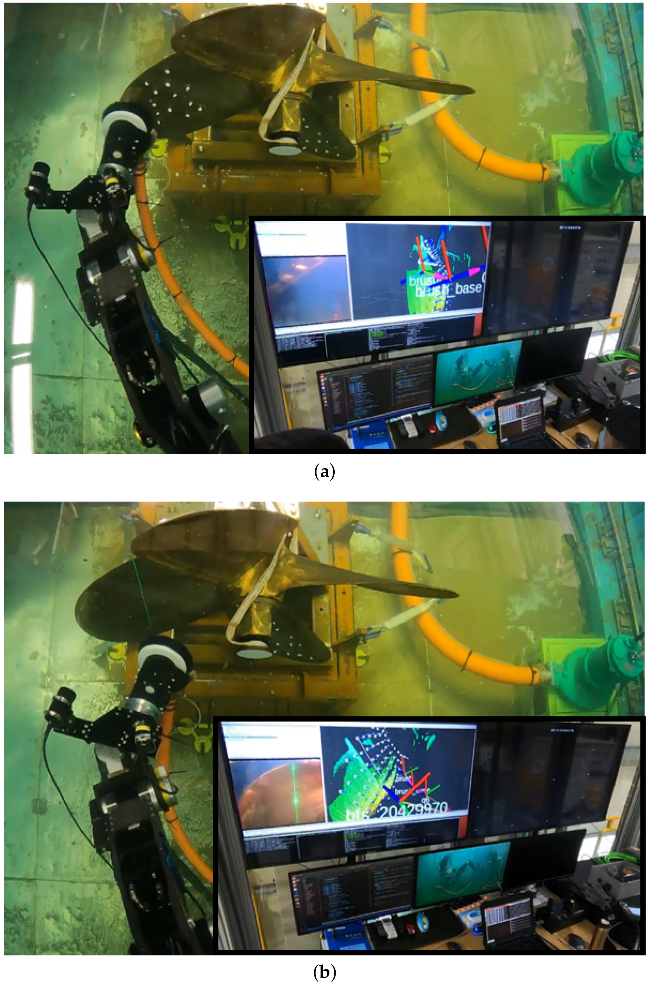
Figure 17.
Autonomous cleaning result (a) before and (b) after cleaning.
Figure 17.
Autonomous cleaning result (a) before and (b) after cleaning.
Figure 18.
Path following results: (a) shows the scanning path-following result, and (b) shows the cleaning path-following result.
Figure 18.
Path following results: (a) shows the scanning path-following result, and (b) shows the cleaning path-following result.
Table 1.
Parameter configurations of body and force elements.
Table 1.
Parameter configurations of body and force elements.
| No. | Body Name | Mass (Kg) | Inertia (Kg·m) |
|---|
| Ixx | Iyy | Izz |
|---|
| 1 | Base frame | 201.75 | 41.75 | 67.25 | 84.4 |
| 2 | UW Base | 38.66 | 0.26 | 0.41 | 0.32 |
| 3 | Boom | 110.77 | 0.94 | 8.41 | 8.59 |
| 4 | Piston B | 2.87 | 1.00 × 10 | 0.04 | 0.04 |
| 5 | Cylinder B | 9.72 | 0.01 | 0.12 | 0.13 |
| 6 | Arm | 72.73 | 2.29 | 2.23 | 0.41 |
| 7 | Piston U | 2.87 | 1.00 × 10 | 0.04 | 0.04 |
| 8 | Cylinder U | 8.81 | 0.01 | 0.08 | 0.09 |
| 9 | Pitch wrist | 29.20 | 0.16 | 0.24 | 0.26 |
| 10 | Yaw wrist | 31.18 | 0.47 | 0.17 | 0.08 |
| 11 | Tool bracket | 18.97 | 0.14 | 0.17 | 0.08 |
| 12 | Tool brush | 23.93 | 0.19 | 0.22 | 0.11 |
| 13 | Propeller | 299.71 | 28.27 | 16.75 | 17.23 |
| 14 | Propeller frame | 2968.58 | 872.57 | 868.98 | 852.16 |
Table 2.
Parameter configurations of joint elements.
Table 2.
Parameter configurations of joint elements.
| No. | Joint Type | Inner Body | Outer Body |
|---|
| 1 | Revolute joint | Base frame | UW Base |
| 2 | Universal joint | UW Base | Piston B |
| 3 | Translational joint | Piston B | Cylinder B |
| 4 | Spherical joint | Cylinder B | Boom |
| 5 | Revolute joint | Base frame | Boom |
| 6 | Revolute joint | Boom | Arm |
| 7 | Universal joint | Arm | Piston U |
| 8 | Translational joint | Piston U | Cylinder U |
| 9 | Spherical joint | Cylinder U | Boom |
| 10 | Revolute joint | Arm | Pitch wrist |
| 11 | Revolute joint | Pitch wrist | Yaw wrist |
| 12 | Revolute joint | Yaw wrist | Tool bracket |
| 13 | Revolute joint | Tool bracket | Tool brush |
| 14 | Revolute joint | Propeller frame | Propeller |
Table 3.
Propeller cleaning experiment results.
Table 3.
Propeller cleaning experiment results.
| No. | Control Error | Num. of Biofouling | Num. of Cleaning | Num. of Recovery | Operation Time |
|---|
| (mm) | (ea) | (%) | (%) | (min s) |
|---|
| 1 | 5.86 | 30 | 25 (83.33) | 17 (68.00) | 7 m 42 s |
| 2 | 5.94 | 24 | 17 (70.83) | 15 (88.24) | 8 m 1 s |
| 3 | 6.66 | 20 | 14 (70.00) | 8 (57.14) | 7 m 50 s |
| 4 | 6.80 | 20 | 20 (100.00) | 18 (90.00) | 7 m 55 s |
| 5 | 6.12 | 20 | 18 (90.00) | 18 (100.00) | 8 m 10 s |
| 6 | 6.02 | 20 | 13 (65.00) | 11 (84.62) | 7 m 48 s |
| Avg. | 6.23 | 134 | 107 (79.85) | 87 (81.31) | 7 m 54 s |
| Disclaimer/Publisher’s Note: The statements, opinions and data contained in all publications are solely those of the individual author(s) and contributor(s) and not of MDPI and/or the editor(s). MDPI and/or the editor(s) disclaim responsibility for any injury to people or property resulting from any ideas, methods, instructions or products referred to in the content. |
© 2023 by the authors. Licensee MDPI, Basel, Switzerland. This article is an open access article distributed under the terms and conditions of the Creative Commons Attribution (CC BY) license (https://creativecommons.org/licenses/by/4.0/).

 ,
, 


