1. Introduction
Estimating the geotechnical properties of marine sediments is crucial for marine resource exploration [
1,
2,
3,
4]. The sensitive clay is a type of marine sediment and is typically composed of very fine-grained particles, such as clay and silt. These properties lead to sensitive clay having unique characteristics, including high sensitivity, high compressibility, and low shear strength; therefore, the estimation of the mechanical properties of sensitive clay is a challenging task in ocean engineering [
5,
6].
The vane shear test (VST) is a common method for measuring the undrained shear strength of clay in geotechnical engineering applications, such as pile capacity and slope stability [
7,
8,
9,
10,
11]. With the expansion of offshore oil exploration in the past few decades, the VST has been widely applied in offshore engineering to measure the strength of marine sediments [
12,
13,
14,
15,
16,
17]. However, due to the lateral instability of the drill pipe, the VST cannot accurately estimate the shear strength of the marine sediments on seabed surfaces that are often encountered at shallow penetrations [
18]. Especially for sensitive clay, the destruction of the clay structure will directly lead to a large deviation in the measurement results.
To solve this problem, the laboratory miniature vane shear test (MVST) has been proposed and used to measure the strength of the sensitive clay obtained from the shallow seabed. The procedure of the MVST involves inserting a vane into the soil sample and then rotating it at a constant rate. The shear strength of the soil can then be calculated based on the measured torque and the dimensions of the vane [
19]. Hernandez et al. [
20] used a fully automatic laboratory miniature vane shear device to measure the undrained shear strength of clay in different states. Zumsteg et al. [
21] used the MVST to measure the undrained shear strength of different mixtures of kaolinite conditioned by foam and polymers. Arulrajah et al. [
22] performed a broad range of geotechnical laboratory tests including MVSTs to evaluate the mechanical properties of the wastewater biosolids. This existing research shows that the MVST is an ideal tool to investigate the undrained shear strength of various types of soils.
It should be noted that the transfer of the soil sample in tube samplers from the seabed to the laboratory releases the in situ confining stress acting on the soils and will increase the soil void ratio and decrease the soil strength. However, the effects of such confining stress on the undrained shear strength are not considered by the existing MVST studies.
The use of the Coupled Eulerian–Lagrangian (CEL) approach has proven to be a valuable tool in studying the MVST for the measurement of sensitive clay. This method has been widely employed by researchers to investigate the MVST and the properties of sensitive clay. Ansari et al. [
23] used the CEL to simulate the complete process of the MVST. Park et al. [
24] developed a miniature vane shear test model to analyze the shear strength of sensitive soil samples with different water contents. Dey et al. [
25] used the CEL to explore the properties of sensitive clay in submarine layers and proposed the numerical model parameters for the sensitive clay. These studies collectively demonstrate the effectiveness of the CEL method in analyzing MVSTs and simulating the properties of sensitive clay.
In this research, a three-dimensional numerical model established by the CEL approach in ABAQUS is used to conduct numerical vane shear tests. Based on the numerical simulation results, we propose a prediction model that considers the confining stress effects and can be used to estimate the undrained shear strength of sensitive clay located beneath shallow seabed surfaces.
2. CEL Modeling in ABAQUS
Numerical simulations of this research were based on the CEL approach in ABAQUS. The CEL approach combines the advantages of both the Eulerian and Lagrangian methods to simulate large deformation problems with a high computational efficiency. The large deformation of soil during the vane shear test can cause the distortion of the mesh, which may affect the accuracy of simulation results. To overcome this challenge, Eulerian analysis is used to calculate the large deformation of the soil sample during the vane shear test, while the Lagrangian analysis is employed to simulate the vane shear device. This approach effectively avoids the mesh distortion and ensures the stability of the simulation calculation results. The coupled Eulerian–Lagrangian interface treatment has been demonstrated as well suited to solve geotechnical problems involving large deformations, such as the pile penetration process [
26] and static cone penetration tests [
27].
2.1. Mesh Algorithm
The Lagrangian analysis employs a discretized numerical solution approach, which entails linking the material properties within the Lagrangian components to the mesh of the numerical model. As the solution process progresses, the material flow causes the mesh to undergo deformation and movement. It is important to note that although the elements undergo deformation, the mass remains constant. The governing equation for Lagrangian analysis is shown as Equation (1) [
28].
where
ρ is the density,
t is the time,
v is the velocity,
σ is the stress, and
b is the body force.
In the Eulerian analysis, the mesh is fixed and the material flows between the elements. The volume of fluid approach is used to monitor interfaces among materials in the multi-material mesh. When materials flow into the mesh, the Eulerian Volume Fraction (EVF) of each material is calculated. The value of the EVF is 1 as the element is filled with materials, and 0 as no material exists. If the sum of all the material volume fractions in an element is less than 1, the rest of the element is automatically packed with the “void” material, which has neither strength nor mass.
In initial calculation, the Eulerian analysis uses the EVF to describe the initial state and position of the material. In the process of numerical simulation, there can be various substances in the Eulerian element, and the material mesh is transmitted to a fixed spatial mesh as a state variable of the Eulerian element. The governing equation of Eulerian analysis is given as Equation (2):
where
ρ is the density,
t is the time,
v is the velocity,
σ is the stress, and
b is the body force.
The constitutive models with strain-softening generally suffer the pathological mesh dependency of the numerical results during the development of the strain localization. However, numerical simulations of this research were based on the CEL framework. In the CEL analysis, the soil material can flow through the fixed Eulerian meshes, which means even if the soil strain in the vane shear test is very large, there will be no mesh-distortion issues [
29].
2.2. The Eulerian Volume Fraction Methods
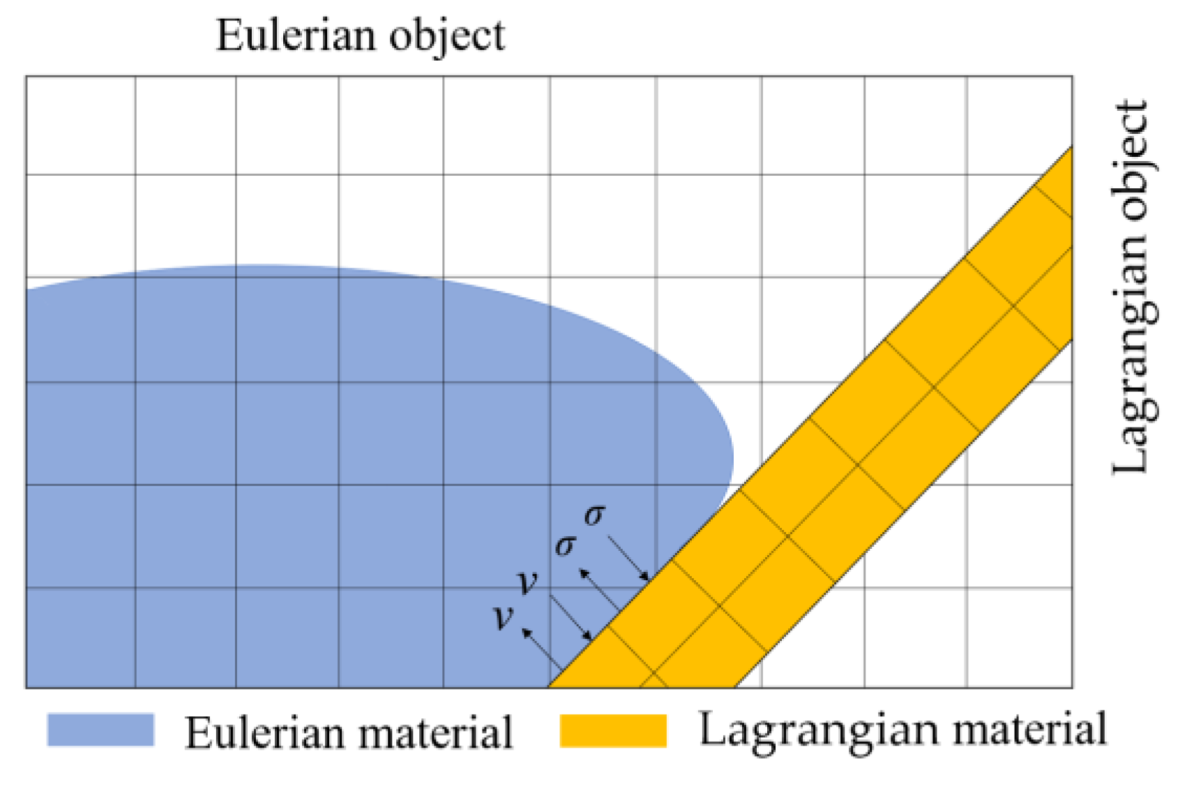
The Eulerian Volume Fraction (EVF) method is an analysis method that involves performing a Boolean comparison operation between the Eulerian object and the Lagrangian reference object, which intersects with the Eulerian object. The result is a scalar dispersion field that corresponds to the proportion of materials in the Eulerian elements. The Boolean comparison operation identifies the overlapping region between two independent objects and determines the volume fraction of each element in the Eulerian objects based on its percentage in the corresponding reference object. This dispersion field labels the region occupied by the Eulerian material in the model.
There are two methods for obtaining the discrete fields in the CEL approach, calculating the volume fraction of the external and internal regions of the Lagrangian reference object. The purpose of calculating the volume fraction of the external region is to create a corresponding material distribution characteristic based on the Lagrangian reference object. While the other method is to create material distribution characteristics in the Eulerian region excluding the Lagrangian part.
2.3. Eulerian–Lagrangian Coupling Interface Treatment
In Lagrangian analysis, the physical quantities including the coordinates, velocity, force, and mass are defined at the nodes of the elements, while the stress, strain, and density are defined at the center of the elements. In Eulerian analysis, these variables are all located at the center of the elements. The Eulerian formulation allows for the transportation of free surfaces and material interfaces on the fixed mesh, but a numerical calculation is required to track the free surface and control numerical dissipation. The coupling algorithm does not require a common node or common surface for the calculation between the Lagrangian and Eulerian mesh. Instead, the coupling surface is used for the interaction between the Lagrangian analysis and the Eulerian analysis. The coupling surface of the Lagrangian element is fixed on the mesh and receives pressure loads from the Eulerian materials from the coupling surface. The coupling surface of the Eulerian element changes in the fixed Eulerian mesh, and the finite volume method is used at each time step to obtain the position of the coupling boundary [
30]. The coupling boundary bears the geometric constraints imposed by the Lagrangian element on the coupling surface. The transfer of the motion and pressure information between the Lagrangian mesh and the Eulerian mesh on the coupling surface satisfies the coordination conditions of the interface, which improves the accuracy of the coupling calculation between the Eulerian and Lagrangian objects. The coupling effect is shown in
Figure 1.
3. CEL Modeling of Vane Shear Test
The numerical simulations of this research were based on the CEL approach in ABAQUS. The CEL approach combines the advantages of both the Eulerian and Lagrangian methods to simulate large deformation problems with a high computational efficiency.
3.1. The Mesh and Geometry of the Model
The numerical model comprises two parts, the soil and the vane shear device, as shown in
Figure 2. The soil is represented as the Eulerian material with eight-node linear bricks with EC3D8R elements. The vane shear device is modeled as the Lagrangian body using S4 elements, which are fully integrated finite–membrane–strain shell elements.
The VST model consists of four rectangular vanes and a soil domain as shown in
Figure 2a. The soil domain is 150 mm × 100 mm × 100 mm. An additional 20 mm of empty space is added above the soil section to allow for the soil movement. We defined the soil domain size according to the ASTM standard [
19] for the vane shear test to ensure the numerical results are not affected by the boundary effect. The height, diameter, and thickness of the vane shear device are 24, 12, and 1 mm, respectively, as shown in
Figure 2b.
3.2. The Strain-Softening Behavior of Sensitivity Clay
Sensitive clay is widely distributed in the ocean. One of the most significant characteristics of sensitive clay is its strain-softening phenomenon. This phenomenon refers to when the sensitive clay reaches a critical state at which its ability to resist further deformation decreases sharply, leading to a rapid increase in the strain and a significant reduction in shear strength.
In this research, Scandinavian sensitive clay [
31] was used in the numerical model. The linear strain-softening model of the sensitive clay is shown in
Figure 3.
su represents the undrained shear strength of the soil at the strain of
γ, where
sup is the peak undrained shear strength before softening, and
suR is the residual undrained shear strength. The pre-peak behavior is elastic until
su reaches
sup and the strain
γ reaches the elastic strain
γe; this linear elastic section is specified by Young’s modulus. Afterward,
su continues to decline with the increase in strain before flattening out at the plastic strain of
.
Table 1 shows the physical and mechanical parameters of the Scandinavian sensitive clay employed in this research. The unit weight, peak shear strength, residual shear strength, and plastic strain are obtained from the experimental data tested by Gylland et al. [
31], and Young’s modulus and Poisson’s ratio are obtained from the numerical simulation data conducted by Kundu et al. [
32].
3.3. The Boundary Conditions
Figure 4 presents the boundary conditions of the soil domain and the vane shear device. Velocities of the elements on the soil domain’s bottom were kept zero in all degrees of freedom (i.e.,
vx =
vy =
vz = 0) and the vertical side surfaces were fixed in a horizontal displacement and free in a vertical displacement (i.e.,
vx =
vy = 0), as shown in
Figure 4a. At the center of the vane shear device, a reference point was selected and a rotation speed of 20°/s was applied [
19], as shown in
Figure 4b.
4. The Numerical Results of the Vane Shear Tests
4.1. Torque of the Vane Shear Test
Figure 5 presents the change of torque values and plastic strain with the increase in the rotation of the vane. It is shown that at the rotation of 5° (Point A), the soil behavior is elastic with no plastic shear strain. Then, as the torque reaches the peak value at the rotation angle of 10° (Point B), the failure occurs from the tips of the blades. During the strain-softening behavior after the torque peak, the plastic strain concentration occurs surrounding the tips and forms a squared-ring shape at the rotation of 15° (Point C), and then the plastic shear strain increases and expands further along the circle (Point D). When the rotation angle exceeds 90° (Point E), the failure spreads circumferentially, forming a full failure plane with a rounded square shape; such a phenomenon was also captured from the experiment tests by Gylland et al. [
31].
To test the reliability of the numerical model in
Figure 5, we compared the torque generated from the numerical model with the torque obtained from the experimental data tested by Gylland et al. [
31], as shown in
Figure 6. Comparisons results show that the values of torque obtained from the numerical model agree well with the results obtained from the experimental tests. The peak torque obtained from the numerical model is 10.21 N·m, which is close to the experimental test with 10.42 N·m.
Figure 7 shows the shear stress of the soil during the VST. As the vane rotates, the shear stress gradually increases until the soil reaches its maximum shear strength at the rotation of 10°, as shown in
Figure 7c. After that, the shear stress acting on the soil decreases to residual strength, as shown in
Figure 7f.
4.2. The Undrained Shear Strength of the Clay
The undrained shear strength of the clay can be estimated from the measured torque value obtained from the vane shear tests, as shown in Equation (3) [
19].
where
Su is the undrained shear strength of the soil sample,
T is the measured torque, and
D is the diameter of the vane.
The torque obtained directly from the vane shear test was converted into the undrained shear strength, yielding the mobilized undrained shear strength of the sensitive clay during the vane shear test. The calculated peak undrained shear strength is 32.37 kPa, and the residual strength is 7.25 kPa.
4.3. The Shear Band of the Clay
The propagation of the shear zone in sensitive clay is one of the critical factors for modeling various types of failure, such as the progressive failure of embankments and submarine landslides [
33].
The shear zone can be divided into three regions: the residual shear zone, the softening zone, and the non-plastic zone according to the values of equivalent plastic shear strain (PEEQVAVG) of each element in the numerical model [
26]. PEEQVAVG can be calculated from the plastic strain
γp of each element, as shown in Equation (4).
When the undrained shear strength su reaches the peak during the vane shear test, the value of the PEEQVAVG is assumed to be equal to 0. When the value of su is up to su95, which is defined as the undrained shear strength reduced by 95% of (sup-suR), the value of the PEEQVAVG = 0.35. When the PEEQVAVG falls within the range of 0–0.35, the soil has reached peak shear strength but has not yet reached residual strength, with a strength reduction of less than 95%, which indicates that the soil is in the softening stage.
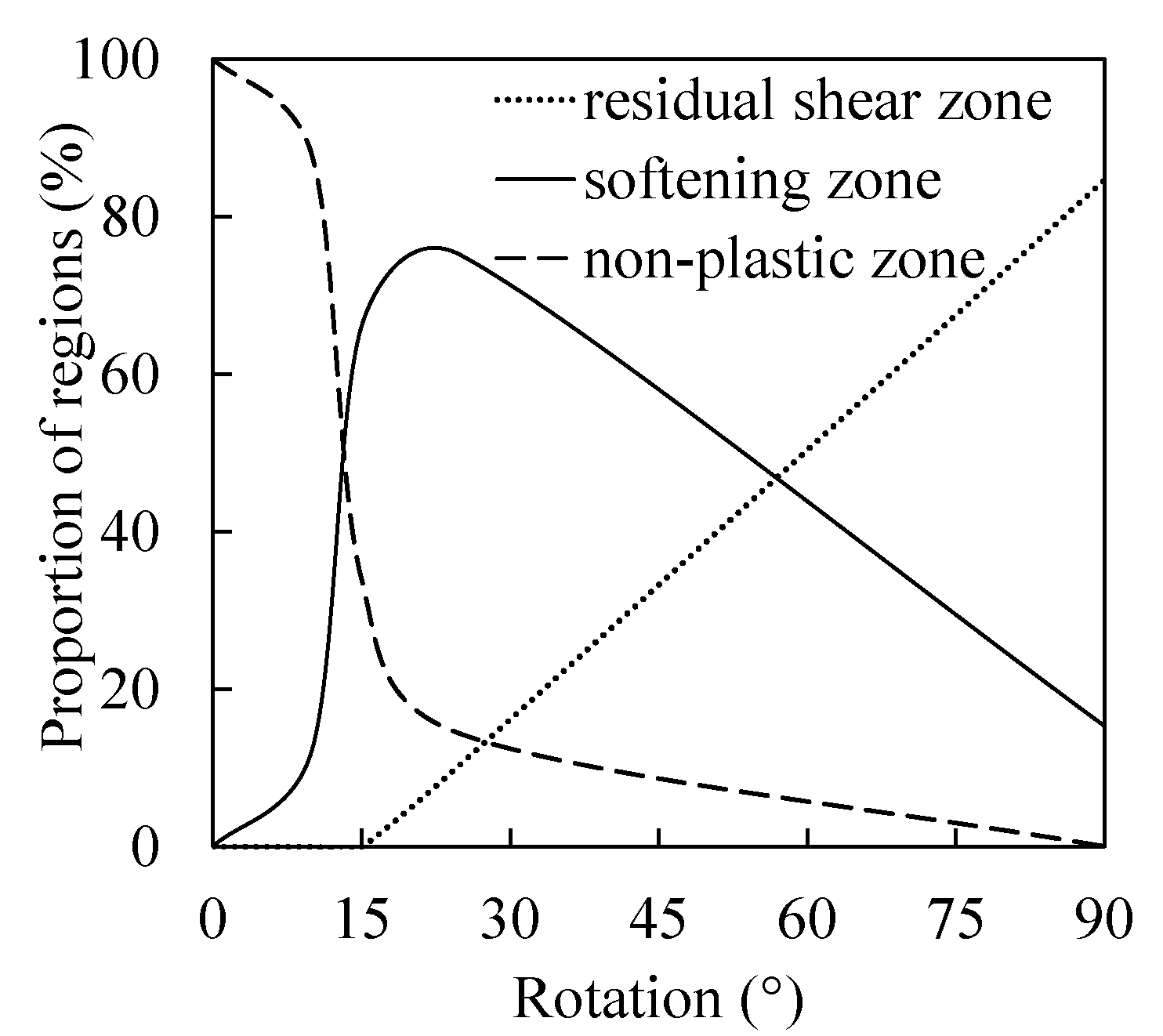
In the numerical model, when the region has a PEEQVAVG ≥ 0.35, the region accumulates a large amount of plastic strain and is defined as the “residual shear zone “; when the region is 0 < PEEQVAVG < 0.35, the region is defined as the “softening zone “; the rest region is defined as the “non-plastic zone”. The values of the PEEQVAVG of numerical models under various rotation conditions during the vane shear tests are used to calculate the types of shear zone, and the results are presented in
Table 2 and plotted in
Figure 8.
It is found that when the vane rotates to 10°, 12.3% of the soil in the shear zone transforms from the non-plastic state to the softening state. When the rotation angle increases to 15°, the proportion of softening zone reaches up to 66.1%. When the blades rotate to 25°, 10.5% of the soil in softening zone becomes completely damaged and turns into a residual stage. When the vane rotation reaches 90°, the proportion of the softening zone reduces to 15.3% and the residual shear zone increased to 84.6%.
5. Comparison Results of the Miniature and Standard Vane Shear Tests
It should be noted that the miniature vane size (
H = 24 mm and
D = 12 mm) presented in
Figure 1 is 5.5 times smaller than that of the standard vane dimension (
H = 130 mm and
D = 65 mm). The larger vanes generate higher levels of torque on the soil, which could lead to an increase in soil disturbance and potential inaccuracies in measurement results. Therefore, in this research, we investigated the relations of undrained shear strength estimated from the miniature and standard vane shear tests, as shown in
Figure 9.
It can be seen that the strength measured by the MVST is higher than that measured by the standard vane shear test. The peak and residual undrained shear strength measured by the MVST are 32.38 kPa and 7.25 kPa, respectively, which are increased by 7.04% and 6.62% compared with 30.25 kPa and 6.80 kPa measured by the standard vane shear test.
The sensitivity
St, which is defined as the ratio of the undisturbed and remolded strengths of sensitive clay, is an important index for characterizing the mechanical behavior of sensitive clay [
34]. We carried out numerical simulations of the vane shear test for sensitive clay with various sensitivities.
Figure 10 presents the comparison results of the undrained shear strength of the soils with an
St from 1 to 7. It presents that, regardless of the sensitivity of the clay, the undrained shear strength measured by the miniature vane shear tests is slightly above the value measured by the standard vane shear tests.
Figure 11 shows that the peak and residual undrained shear strength of the sensitive clay obtained from the miniature vane shear tests are about 1.07 times that of the standard vane shear tests.
sum and
sus are the undrained shear strength measured by the MVST and standard VST, respectively.
6. Miniature Vane Shear Test under Confining Stress Conditions
The process of transferring soil samples from tube samplers on the seabed to the laboratory can release the in situ confining stress acting on the soil, which can increase the soil void ratio and decrease the soil strength. Therefore, it is necessary to investigate the influence of the confining stress on the undrained shear strength measured with the MVST. The static earth pressure
σ0 can be used to represent the confining stress acting on the soil under various depths and can be calculated from Equation (5).
where
K0 is the coefficient of static earth pressure,
γ is the unit weight of the soil sample, and
z is the depth.
For sensitive clay, the values of
K0 always fall within the range of 0.5–1.5, with 0.5 often serving for
K0 in the case of Norwegian sensitive clays [
35]. In this research, confining stresses are applied to the soil sample during the numerical MVST to represent the in situ confining stress state of soils under shallow seabed surfaces.
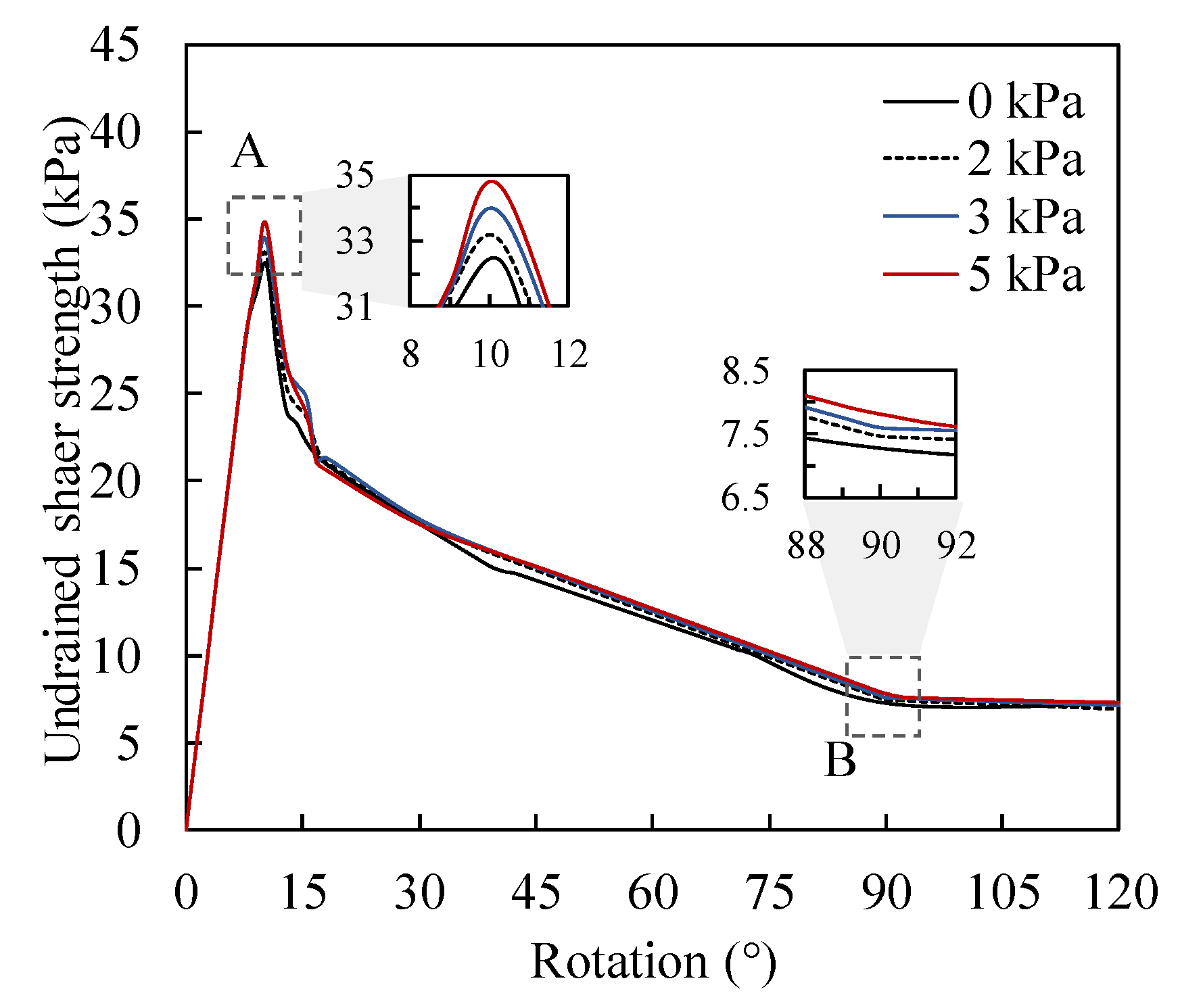
Figure 12 presents the undrained shear strength of soil samples under different confining stress conditions. The values of confining stress are 2 kPa, 3 kPa, and 5 kPa, representing the soil samples taken from the seabed under the depths of 24 cm, 36 cm, and 60 cm, respectively. It is shown that the undrained shear strength increases with the increase in confining stress. The values of peak strength are 32.37 kPa, 32.93 kPa, 33.79 kPa, and 34.66 kPa, and the residual strengths were 7.25 kPa, 7.44 kPa, 7.58 kPa, and 7.78 kPa when the soil samples were under the confining stress state of 0, 2 kPa, 3 kPa, and 5 kPa, respectively.
Figure 13 presents the normalized undrained peak shear strength and residual strength.
s’u and
su0 are the undrained shear strength of soils obtained from soil samples under certain confining stress and no confining stress states, respectively.
It is found that both the undrained peak and residual strength of the soil sample exhibit a linear increase with an increase in confining stress. A linear curve fitting method can be used to quantify the effects of confining stress on the undrained shear strength of sensitive clay, as shown in Equation (6).
where
s’u is the undrained shear strength of the soil under certain confining stress,
σ3 is the confining stress, and
su0 is the undrained shear strength of the soil sample under no confining stress.
As the results presented in
Figure 10 show, the peak and residual undrained shear strengths of the soil samples obtained from the MVST are about 1.07 times that of the standard vane shear test. Therefore, a correction factor
μ = 1.07 is suggested to adjust Equation (6) to eliminate the size effect caused by blades, and the modified equation is shown in Equation (7).
Equation (7) can not only reflect the effect of confining stress on the undrained shear strength of the soil samples obtained from the MVST but also can eliminate the size effect caused by the vane blades of MVSTs. Therefore, it can be used to estimate the undrained shear strength of the sensitive clay under shallow seabed surfaces.
7. Conclusions
In this research, three-dimensional vane shear test (VST) models were constructed using the Coupled Eulerian–Lagrangian (CEL) approach in ABAQUS to investigate the vane blade size effects and confining stress effects on the undrained shear strength of sensitive clay. The main conclusions are as follows:
The numerical simulations show that the failure of the soil sample initiates from the tips of the blades and propagates circumferentially. With the increase in rotation angle, the plastic shear strain extends surrounding the tips and forms a squared-ring shape. At the rotation of 90°, a complete failure plane of a rounded square shape is formed, which is consistent with the experiment results.
The undrained shear strength of the soil samples obtained from the miniature vane shear test (MVST) is 1.07 times that of the standard VST. Therefore, a correction factor μ = 1.07 is suggested to adjust the undrained shear strength values estimated from the MVST for engineering applications.
Both undrained peak and residual shear strength of the soil samples exhibit a linear increase with the increase in confining stress. Therefore, a linear prediction model that can reflect the confining stress effects on the undrained shear strength of the soil samples obtained from the MVST was proposed. It can be used to estimate the undrained shear strength of the sensitive clay under shallow seabed surfaces.
The finding of this research is based on the numerical simulation, which is open for further improvements as the miniature vane shear test apparatus considering confinement conditions is available.
Author Contributions
Conceptualization, J.S.; methodology, J.S., X.W. and Q.C.; software, X.W. and Q.C.; validation, X.W.; formal analysis, X.W. and J.S.; investigation, Q.G. and Z.Y.; resources, J.S. and J.C.; writing—original draft preparation, J.S. and X.W.; writing—review and editing, J.S., X.W., Q.C., Z.Y. and Q.G.; visualization, X.W.; supervision, J.S. and J.C.; project administration, J.S. and J.C.; funding acquisition, J.S. and J.C. All authors have read and agreed to the published version of the manuscript.
Funding
This research was funded by the Zhoushan Science and Technology Plan Project, grant number 2022C81001; the Jointed Funding Key Projects of Zhejiang Province, grant number LHZ22E090002; the Key R&D of Zhejiang Province, grant number 2021C03183; the Sanya Yazhou Bay Science and Technology City, grant number KYC-2020-01-001; the Finance Science and Technology Project of Hainan Province, grant number ZDKJ202019; and a project supported by the Scientific Research Fund of the Zhejiang Provincial Education Department, grant number Y202250867.
Institutional Review Board Statement
Not applicable.
Informed Consent Statement
Not applicable.
Data Availability Statement
The data used to support the findings and results of this study are available from the corresponding author upon request.
Conflicts of Interest
The authors declare no conflict of interest.
References
- Zhou, P.; Chen, J.; Ruan, D.; Peng, X.; Wu, X.; Ren, Z.; Gao, Q. Design of a Marine Sediments Resistivity Measurement System Based on a Circular Permutation Electrode. J. Mar. Sci. Eng. 2021, 9, 995. [Google Scholar] [CrossRef]
- He, S.; Peng, Y.; Jin, Y.; Wan, B.; Liu, G. Review and Analysis of Key Techniques in Marine Sediment Sampling. Chin. J. Mech. Eng. 2020, 33, 1–17. [Google Scholar] [CrossRef]
- Sørlie, E.R.; Hartnik, L.O.; Tran, Q.A.; Eiksund, G.R.; Thakur, V.; Kjennbakken, H.; Degago, S. Physical model tests of clay-rich submarine landslides and resulting impact forces on offshore foundations. Ocean Eng. 2023, 273, 113966. [Google Scholar] [CrossRef]
- Sun, Z.; Kong, G.; Zhou, Y.; Shen, Y.; Xiao, H. Thixotropy of a Transparent Clay Manufactured Using Carbopol to Simulate Marine Soil. J. Mar. Sci. Eng. 2021, 9, 738. [Google Scholar] [CrossRef]
- Wang, C.; Hawlader, B.; Perret, D.; Soga, K. Effects of geometry and soil properties on type and retrogression of landslides in sensitive clays. Géotechnique 2022, 72, 322–336. [Google Scholar] [CrossRef]
- Lin, Y.; Qin, H.; Guo, J.; Chen, J. Study on the Rheological Behavior of a Model Clay Sediment. J. Mar. Sci. Eng. 2021, 9, 81. [Google Scholar] [CrossRef]
- Flaate, K. Factors Influencing the Results of Vane Tests. Can. Geotech. J. 1966, 3, 18–31. [Google Scholar] [CrossRef]
- Kouretzis, G.P.; Pineda, J.; Krabbenhoft, K.; Wilson, L. Interpretation of vane shear tests for geotechnical stability calculations. Can. Geotech. J. 2017, 54, 1775–1780. [Google Scholar] [CrossRef]
- He, C.; You, Y.; Wang, D.; Wu, H. Estimating soil failure due to torsion via vane shear test by varying vane diameter and soil properties. Soil Tillage Res. 2018, 177, 68–78. [Google Scholar] [CrossRef]
- Jiang, S.H.; Papaioannou, I.; Straub, D. Bayesian updating of slope reliability in spatially variable soils with in-situ measure-ments. Eng. Geol. 2018, 239, 310–320. [Google Scholar] [CrossRef]
- Saye, S.R.; Kumm, B.P.; Lutenegger, A.J. Estimating over consolidation ratio (OCR) in structured and unstructured cohesive soil with field vane tests referencing soil index properties. Can. Geotech. J. 2021, 58, 125–141. [Google Scholar] [CrossRef]
- Zhang, H.; Jia, Y.; Liu, X.; Wei, Z.; Ji, C.; Jiao, X.; Zhu, C. Progress in in-situ measurement of sediment mechanical properties for full ocean depth. Mar. Geol. Front. 2019, 35, 1–9. [Google Scholar]
- Lunne, T.; Andersen, K.H.; Low, H.E.; Randolph, M.F.; Sjursen, M. Guidelines for offshore in situ testing and interpretation in deepwater soft clays. Can. Geotech. J. 2011, 48, 543–556. [Google Scholar] [CrossRef]
- Ma, W.-B.; Rao, Q.-H.; Li, P.; Guo, S.-C.; Feng, K. Shear creep parameters of simulative soil for deep-sea sediment. J. Central South Univ. 2014, 21, 4682–4689. [Google Scholar] [CrossRef]
- Kolk, H.J.; Hooper, J.; Imms, B.W. Evaluation of offshore in situ vane test results. In Vane Shear Strength Testing of Soils: Field and Laboratory Studies; Richards, A.J., Ed.; ASTM STP 1014; American Society for Testing and Materials: Philadelphia, PA, USA, 1988; pp. 339–353. [Google Scholar]
- Zhang, H.; Liu, X.; Chen, A.; Li, W.; Lu, Y.; Guo, X. Design and Application of an In Situ Test Device for Rheological Characteristic Measurements of Liquefied Submarine Sediments. J. Mar. Sci. Eng. 2021, 9, 639. [Google Scholar] [CrossRef]
- Wang, K.; Xu, G.; Wang, J.; Wang, C. Self-boring in situ shear pressuremeter testing of clay from Dalian Bay, China. Soils Found. 2018, 58, 1212–1227. [Google Scholar] [CrossRef]
- Young, A.G.; McClelland, B.; Quiros, G.W. In-Situ Vane Shear Testing at Sea. In Vane Shear Strength Testing of Soils: Field and Laboratory Studies; Richards, A.J., Ed.; ASTM STP 1014; American Society for Testing and Materials: Philadelphia, PA, USA, 1988; pp. 46–67. [Google Scholar]
- ASTM D 4648; Standard Test Method for Laboratory Miniature Vane Shear Test for Saturated Fine-Grained Clayey Soil. American Society for Testing and Materials: West Conshohocken, PA, USA, 2011.
- Alberto-Hernandez, Y.; Kang, C.; Yi, Y.; Bayat, A. Mechanical properties of clayey soil relevant for clogging potential. Int. J. Geotech. Eng. 2017, 1, 1–8. [Google Scholar] [CrossRef]
- Zumsteg, R.; Plötze, M.; Puzrin, A. Effect of Soil Conditioners on the Pressure and Rate-Dependent Shear Strength of Different Clays. J. Geotech. Geoenviron. Eng. 2012, 138, 1138–1146. [Google Scholar] [CrossRef]
- Arulrajah, A.; Disfani, M.M.; Suthagaran, V.; Bo, M.W. Laboratory Evaluation of the Geotechnical Characteristics of Wastewater Biosolids in Road Embankments. J. Mater. Civ. Eng. 2013, 25, 1682–1691. [Google Scholar] [CrossRef]
- Ansari, Y.; Pineda, J.; Kouretzis, G.; Sheng, D. Experimental and numerical investigation of rate and softening effects on the undrained shear strength of Ballina clay. Aust. Geomech. 2014, 49, 51–57. [Google Scholar]
- Park, S.-S.; Doan, N.-P.; Jeong, S.W. Numerical simulation of water content dependent undrained shear strength of clays. Mar. Georesour. Geotechnol. 2019, 38, 621–632. [Google Scholar] [CrossRef]
- Dey, R.; Hawlader, B.; Phillips, R.; Soga, K. Large deformation finite-element modelling of progressive failure leading to spread in sensitive clay slopes. Géotechnique 2015, 65, 657–668. [Google Scholar] [CrossRef]
- Qiu, G.; Henke, S.; Grabe, J. Application of a Coupled Eulerian–Lagrangian approach on geomechanical problems involving large deformations. Comput. Geotech. 2011, 38, 30–39. [Google Scholar] [CrossRef]
- Gupta, T.; Chakraborty, T.; Abdel-Rahman, K.; Achmus, M. Large Deformation Finite Element Analysis of Static Cone Penetration Test. Indian Geotech. J. 2015, 46, 115–123. [Google Scholar] [CrossRef]
- Vitali, E.; Benson, D.J. Contact with friction in multi-material arbitrary Lagrangian-Eulerian formulations using X-FEM. Int. J. Numer. Methods Eng. 2008, 76, 893–921. [Google Scholar] [CrossRef]
- Shen, J.; Chen, Q.; Wang, L.-Z.; Wang, D. Numerical Investigations of the Failure Mechanism of Spreading Landslides. Can. Geotech. J. 2023. [Google Scholar] [CrossRef]
- Benson, D.J.; Okazawa, S. Contact in a multi-material Eulerian finite element formulation. Comput. Methods Appl. Mech. Eng. 2004, 193, 4277–4298. [Google Scholar] [CrossRef]
- Gylland, A.; Jostad, H.; Nordal, S.; Emdal, A. Micro-level investigation of the in situ shear vane failure geometry in sensitive clay. Geotechnique 2013, 63, 1264–1270. [Google Scholar] [CrossRef]
- Kundu, P.; Hawlader, B.; Karmaker, R. Two-dimensional finite element modelling of field vane shear test in sensitive clay. In Proceedings of the 74th Canadian Geotechnical Conference, Niagara, ON, Canada, 26–29 September 2021. [Google Scholar]
- Quinn, P.; Diederichs, M.; Rowe, R.K.; Hutchinson, D. A new model for large landslides in sensitive clay using a fracture mechanics approach. Can. Geotech. J. 2011, 48, 1151–1162. [Google Scholar] [CrossRef]
- Cotecchia, F.; Chandler, R.J. A general framework for the mechanical behaviour of clays. Géotechnique 2000, 50, 431–447. [Google Scholar] [CrossRef]
- Wang, C.; Hawlader, B.; Perret, D.; Soga, K.; Chen, J. Modeling of initial stresses and seepage for large deformation fi-nite-element simulation of sensitive clay landslides. J. Geotech. Geoenviron. Eng. 2021, 147, 04021111. [Google Scholar] [CrossRef]
| Disclaimer/Publisher’s Note: The statements, opinions and data contained in all publications are solely those of the individual author(s) and contributor(s) and not of MDPI and/or the editor(s). MDPI and/or the editor(s) disclaim responsibility for any injury to people or property resulting from any ideas, methods, instructions or products referred to in the content. |
© 2023 by the authors. Licensee MDPI, Basel, Switzerland. This article is an open access article distributed under the terms and conditions of the Creative Commons Attribution (CC BY) license (https://creativecommons.org/licenses/by/4.0/).


