Article

Multi-Criteria Analysis to Determine the Most Appropriate Fuel Composition in an Ammonia/Diesel Oil Dual Fuel Engine

by
Carlos Gervasio Rodríguez
1,
María Isabel Lamas
2,*,
Juan de Dios Rodríguez
2 and
Amr Abbas
3
1
Nautical Sciences and Marine Engineering Department, University of Coruña, Mendizabal s/n, 15403 Ferrol, Spain
2
Escola Politécnica de Enxeñaría de Ferrol, Campus Industrial de Ferrol, University of Coruña, Mendizabal s/n, 15403 Ferrol, Spain
3
Department of Mechanical Engineering, Mississippi State University, Starkville, MS 39762, USA
*
Author to whom correspondence should be addressed.
J. Mar. Sci. Eng. 2023, 11(4), 689; https://doi.org/10.3390/jmse11040689
Submission received: 19 February 2023 / Revised: 18 March 2023 / Accepted: 19 March 2023 / Published: 24 March 2023
(This article belongs to the Special Issue Marine Engines Performance and Emissions Ⅲ)

Abstract

:
The possibility to employ alternative fuels is gaining special interest in the marine sector. There are several suitable candidates for traditional fossil fuels substitution. Among them, ammonia is a promising solution that allows progress on decarbonization since the ammonia molecule does not contain carbon. Hence, the present work analyzes the use of ammonia as a potential fuel for a marine engine. Particularly, a dual fuel mode ammonia/diesel oil operation is proposed. As expected, the carbon dioxide emissions are reduced as the proportion of ammonia is increased. Nevertheless, other non-desirable substances are generated such as non-reacted ammonia, NOx and N2O. Due to these opposing effects, a multi-criteria analysis is proposed to characterize the most appropriate proportion of ammonia in the fuel. The environmental damage of the different pollutants was considered. Due to the important environmental adverse effects of NOx and N2O, only a maximum 20% ammonia percentage on the fuel was obtained as the most appropriate option. A higher ammonia content leads to excessive concentrations of NOx and N2O being emitted to the environment.

1. Introduction

The negative impact of the maritime transport on the environment constitutes an important issue in these current times. Several harmful substances are emitted by marine engines such as carbon dioxide (CO2), particulates, nitrogen oxides (NOx), and sulphur oxides (SOx), etc. Accordingly, several reduction measurements have been successfully developed in recent years and emission levels from current engines have been substantially reduced [1,2,3]. Regarding NOx, efficient measurements have been developed such as EGR (exhaust gas recirculation), water addition, variation of the distribution diagram, modification of the injection pattern, post-treatments of the exhaust gases, etc. [4,5,6]. Regarding SOx, the solution to reduce these emissions is to employ low sulphur content fuels or post treatments of the exhaust gas with scrubbers [7,8]. Particulate emissions are mainly reduced by filters. Regarding CO2, unfortunately there is no efficient technology to treat these emissions nowadays. The solution consists thus on employing alternative fuels [9,10,11,12,13,14,15,16,17]. Several fuels are candidates to substitute traditional fossil fuels such as LNG, methanol, biodiesel, hydrogen, ammonia, etc. In order to progress on the decarbonization of the maritime sector it is necessary to employ fuels that do not contain carbon on the molecule, such as ammonia (NH3) and hydrogen (H2) [18,19,20,21]. Between these two alternatives, ammonia presents several advantages: the production and logistic technologies are well known and storage can be realized at more moderate pressure and temperature than hydrogen [22,23], which is difficult to store. Due to these reasons, ammonia seems to be the most promising carbon-free marine fuel for the future [24,25,26,27,28] despite some disadvantages such as price, storage space on a ship, etc. [29,30,31,32]. Accordingly, the present work proposes ammonia as an alternative fuel, in particular, a dual fuel operation ammonia/diesel oil. In a previous work, Rodríguez et al. [33] carried out a numerical model to analyze the ammonia/diesel operation in the MAN D2840LE V10. Under a constant power of 320 kW, the percentage of power contribution from ammonia varied from 0 to 90%. The results are shown in Figure 1, which illustrates the efficiency and emissions of CO2, NOx, NH3, and N2O against the percentage of power contribution from ammonia. As can be seen in this figure, CO2 emissions are reduced as the proportion of ammonia in the fuel is increased. Nevertheless, NOx may be increased under some conditions. Other unavoidable substances associated to ammonia combustion are N2O and NH3 slip (that is, NH3 that has not reacted and is emitted with the exhaust gases). These opposed effects make the procedure too difficult to select the most appropriate proportion of ammonia in an ammonia/diesel oil dual fuel engine. In this regard, multiple-criteria decision-making (MCDM) procedures constitute useful tools to perform the decision process. These techniques can be applied to select the most appropriate alternative when there are conflicting criteria and can be used in many different fields. Among the multiple applications, these techniques are very useful in decision-making processes related to engines [34,35].
Ammonia was first used as a fuel in 1822 by Sir Goldsworthy Gurney. At that time, its use was soon detracted mainly due to the high cost in comparison with fossil fuels and toxicity. In recent years, the use of ammonia as a fuel has been recovered due to environmental issues. It is worth mentioning that although the application of ammonia as fuel was known many years ago, its research is still in its infancy and needs to be developed before being implemented as marine fuel. An important disadvantage of experimental setups is the danger due to the toxicity of ammonia [36]. Therefore, the present paper proposes a computational fluid dynamics (CFD) analysis to determine the level emissions under several ammonia/diesel oil proportions. Particularly, CO2, NOx, NH3 and N2O were characterized. In order to determine the most appropriate ammonia proportion in the fuel, an MCDM approach was developed and the emissions valued in terms of environmental factors. The main contribution of this work consists of proposing a formal tool to select the most appropriate proportion of ammonia in the case where conflicting criteria complicates the decision-making process.

2. Materials and Methods
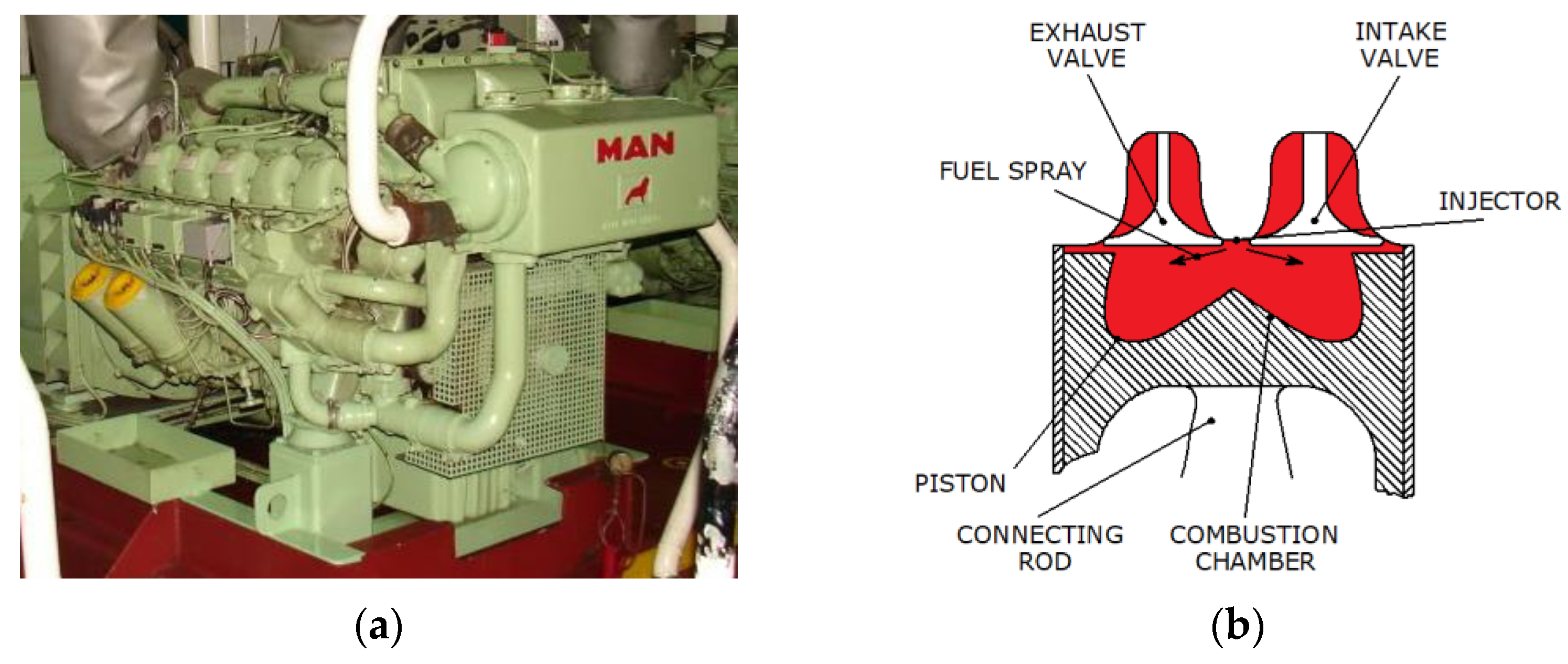
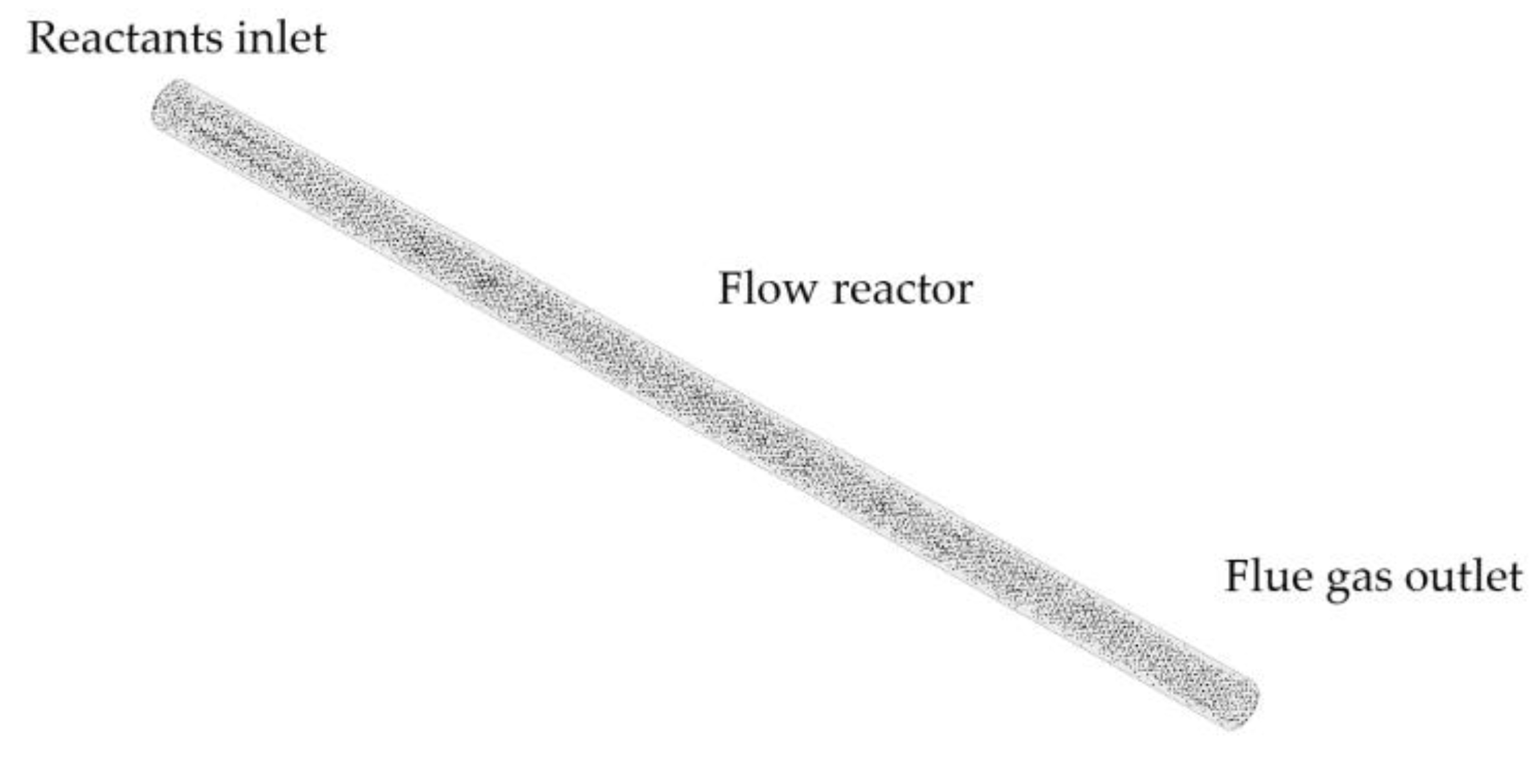
This section describes the engine analyzed as well as the CFD and MCDM models.

2.1. CFD Model

The engine analyzed in the present work is the MAN D2840LE V10 (Figure 2a). It is a four-stroke diesel engine, supercharged, with direct injection. It consists of 10 V-shaped cylinders arranged at 90°, with a unit displacement volume of 1827 cm3/cylinder. This study was conducted with the engine running at full load, developing a power of 320 kW at a speed of 1500 rpm. Figure 2b shows the section of each cylinder in the top dead center (TDC) position. The diesel oil injector is placed in the centre of the combustion chamber and injects the fuel in the form of a spray.
Computational fluid dynamics procedures consist on discretizing both the domain and governing equations. The domain discretization, also called grid or mesh, is shown in Figure 3. Particularly, the 3D mesh at BDC (bottom dead center) position is shown in Figure 3a, while Figure 3b shows the AA section at BDC position and Figure 3c the AA section at TDC position. This mesh corresponds to the red part illustrated in the previous Figure 2b.
A mesh size sensitivity analysis was carried out in order to ensure that this mesh is appropriate for these simulations. The following three meshes were compared.
-
Mesh 1: number of elements from 26,000 at TDC to 375,000 at BDC.
-
Mesh 2: number of elements from 32,000 at TDC to 450,000 at BDC.
-
Mesh 3: number of elements from 39,000 at TDC to 540,000 at BDC.
The results obtained with these three meshes are shown in Table 1. This table shows the error between the experimental and numerical results of SFC, CO2, NOx using three meshes and three time-step values. As can be seen, Mesh 1 provided acceptable accuracy, but Meshes 2 and 3 were more accurate. Since the errors obtained with Meshes 2 and 3 were too similar and Mesh 3 was too expensive computationally, Mesh 2 was selected for the computations. The time step was also analyzed, particularly the three values shown in Table 1. As can be seen, 0.9 × 10⁻⁵ and 1.1 × 10⁻⁵ s time steps provided the same errors. In accordance with this, a 1.1 × 10⁻⁵ s time steps was selected.
The simulations were carried out through the free software OpenFOAM. They are based on the equations of conservation of mass, momentum and energy. In addition, an additional equation was added for each species involved. The details of the numerical model applied to this engine have been described in previous works [37,38,39] and thus only a brief summary of the numerical model is described herein. The fuel droplet breakup was treated through the Kelvin-Helmholtz and Rayleigh-Taylor breakup models, and the heat-up and evaporation of the droplets through the Dukowicz model. As a diesel oil combustion model, the kinetic scheme of Ra and Reitz [40] was employed. As an NOx formation model, the kinetic scheme proposed by Yang et al. [41] was employed. As an NOx reduction model, the kinetic scheme proposed by Miller and Glarborg [42] was employed. As an ammonia combustion model, the kinetic scheme proposed by Mathieu and Peterson [43] was employed. The validation between numerical and experimental results is illustrated in Figure 4 and Figure 5. A Gasboard-3000 analyzer was used to characterize NOx and CO2 emissions (3% NOx accuracy, 2% CO2 accuracy) and MALIN 6000 to characterize the pressure field (1% accuracy). As can be seen, Figure 4 and Figure 5 show a reasonable concordance between the experimental and numerical results, which supports the suitability of the numerical model to analyze this engine. Ammonia was not employed in the experimental setups due to its toxicity. An accident during the experiments could easily cause the immediate death of the people who handle it.
Regarding the validation of the kinetic schemes related to ammonia, an experiment from the literature was reproduced through CFD. In particular, the flow reactor measurements from Hulgaard and Kim Dam-Johansen [44] were employed. These authors used a cylindrical flow reactor with a 5.1 mm diameter and 14 cm length and characterized the emissions of NH3, NO, and N2O produced by oxidation of ammonia under several temperatures. In order to validate the model, these experiments were reproduced through CFD. The mesh is shown in Figure 6 and the comparison between the numerical simulations and the experimental results of Hulgaard and Kim Dam-Johansen [44] is shown in Figure 7. These results correspond to 800 ppm initial ammonia concentration. As can be seen, a reasonable agreement was obtained, which ratifies the accuracy of the kinetic schemes employed for ammonia in the present work.
Once the numerical model was established and validated, the next step was to analyze the dual mode ammonia/diesel oil. It is well known that the implementation of ammonia in SI (spark ignition) engines does not present excessive limitations. However, the implementation in CI (compression ignition) engines presents a very important drawback since an excessive compression ratio is required for the autoignition of ammonia. This is required because ammonia presents a very high autoignition temperature [45]. This fact limits the use of 100% ammonia as fuel in CI engines [46,47,48,49]. In the present work, it was interesting to maintain the operation as a CI or Diesel cycle due to its higher performance over an SI or Otto cycle. This is the reason for the inclination towards a dual fuel performance ammonia/diesel oil as fuel. The injection of ammonia was modeled by injecting it into the air intake manifold, so that the injection of diesel oil is that which ignites the ammonia-air mixture (i.e., the one that starts combustion once the ammonia-air mixture is compressed).

2.2. MCDM Model

As indicated previously, an MCDM model was employed to determine the most appropriate percentage of power contribution from ammonia. All simulations were carried out under a constant power, 320 kW since this is the nominal power of the engine. Several ammonia/diesel oil proportions were analyzed under this constant power. The power contribution from ammonia or diesel oil was computed by the product of the mass flow by the lower heating value. According to this, the percentage of power contribution from ammonia, E ˙ a m m o n i a , was computed by Equation (1).
E ˙ a m m o n i a = m ˙ a m m o n i a L H V a m m o n i a m ˙ a m m o n i a L H V a m m o n i a + m ˙ d i e s e l   o i l L H V d i e s e l   o i l × 100
where m ˙ a m m o n i a and m ˙ d i e s e l   o i l represent the mass flow of ammonia and diesel oil, respectively. LHVammonia and LHVdiesel oil are the lower heating value of ammonia (18.6 MJ/kg) and diesel oil (42.4 MJ/kg), respectively.
The mass flow of ammonia and diesel oil required to obtain 320 kW power is shown in Figure 8. The range from 0% ammonia (i.e., 100% diesel oil) to 90% ammonia (i.e., 10% diesel oil) was analyzed. Obviously, as the percentage of power contribution from ammonia is increased, the mass flow of ammonia is higher and the mass flow of diesel oil lower. The relation is not exactly linear due to thermal efficiency—Figure 1 and Equation (2)—which is reduced as the percentage of power contribution from ammonia is increased. The use of ammonia reduces the thermal efficiency because ammonia presents a slow combustion and some non-reacting ammonia is emitted through the exhaust gases. Moreover, as more ammonia percentage is used, the temperatures and pressures are reduced too and thus the thermal efficiency.
η = W ˙ m ˙ a m m o n i a L H V a m m o n i a + m ˙ d i e s e l   o i l L H V d i e s e l   o i l × 100
where W ˙ is the output power, that is, 320 kW for all simulations.
The MCDM procedure applied in the present work is based on the four steps indicated below.
1-
Establishment of the decision matrix
The decision matrix, DM, contains the data that will be used in the MCDM procedure. It consists of an m × n matrix—Equation (3)—where m is the number of alternatives and n is the number of criteria that will be considered in the decision-making process. In Equation (3), Xij refers to each value of the decision matrix (row i column j), corresponding to the value of alternative i under criterion j.
D M = ( X 11 X 1 n X m 1 X m n )
In the present work, a range of percentage of power contribution from ammonia was analyzed between 0 and 90%. Specifically, 10 alternatives were analyzed using 0%, 10%, 20%, 30%, 40%, 50%, 60%, 70%, 80%, and 90%. Four criteria were considered: CO2, NOx, NH3, and N2O. Taking into account these quantities of alternatives and criteria, a 10 × 4 decision matrix results in 10 rows and 4 columns.
2-
Establishment of the weights
Another issue in MCDM analyses is the establishing of the criteria weights. These represent the degree of importance assigned to each criterion.
The methods to establish the criteria weights can be divided into objective and subjective. Regarding objective methods, several procedures have been proposed in the literature: CRITIC (CRiteria Importance Through Intercriteria Correlation), entropy, standard deviation, variance, etc. These procedures are based on mathematical expressions, mainly related to statistical aspects which provide less importance to uncertain data, that is, data that are different from the mean. On the other hand, subjective methods are based on estimation from experts in the field.
Subjective methods are recommended and are more frequently employed in practical applications [50]. The reason is that the weights are set by experts who know the subject very well. Objective methods are only appropriate when the objectivity of the analysis is important or when there is no clear agreement between the experts [51].
In the present work, it is important to consider the pollution damage of the different exhaust emissions [52,53,54,55]. This aspect was taken into account to set the different weights. Besides, practical aspects were also taken into account. Although NOx are a harmful gases, it is worth noting that that efficient catalyzers are currently available to reduce them. Regarding NH3 and N2O, these are pollutants associated to ammonia combustion and it is expected that in the coming years research will be carried out on techniques to reduce them. Another important aspect to take into account is that ammonia burns slowly, and thus its use in slow engines is more appropriate than in fast engines. As indicated above, a fast engine running at 1500 rpm has been used in the present work. A slow engine would emit a lower amount of unreacted ammonia because there would be more time for the combustion of the ammonia to take place. These aspects were taken into account to recommend the following weighs: CO2 20% (0.2), NOx 25% (0.25), NH3 50% (0.5), and N2O 5% (0.05).
Since the determination of the criteria weights highly affects the result of a decision-making problem, the present work considers several combinations of weights and the effect on the results. These will be illustrated in the results and discussion section.
3-
Normalization
Another important step in MCDM analyses is normalizing the decision matrix. The purpose of this process is to set the different alternatives into a same range in order to compare them. The normalization allows working in dimensionless form and comparing the different data, that is, the measurable values are converted into comparable ones. Many normalization techniques can be found in the literature [56,57]. The most employed normalization techniques include linear max normalization, linear sum normalization, linear max-min normalization, logarithmic normalization, vector normalization, etc. In the present work, the linear max normalization technique was employed. According to this procedure, each normalized value in the decision matrix is given in Equation (4). Since in the present work all are non-beneficial criteria, that is, it is desirable to reduce as much as possible all of them (CO2, NOx, NH3, and N2O), this normalization converts the results to a range between 0 and 1—Xij,min/Xj,max. The normalized value 0 is assigned to the maximum values of CO2, NOx, NH3, and N2O, which correspond to non-desirable results. On the other hand, the maximum normalized values are assigned to the minimum values of CO2, NOx, NH3, and N2O, which correspond to desirable results.
V i j = 1 X i j X j , max
In Equation (4) above, Vij refers to each normalized value, and Xj,max the maximum value corresponding to each criterion. The normalized decision matrix (NDM), Equation (5), is an m × n matrix with each data normalized.
N D M = ( V 11 V 1 n V m 1 V m n )
4-
Calculation of the most appropriate option
The most appropriate alternative was computed through a parameter called adequacy index. Several procedures are available in the literature to compute the most appropriate option: WSM (weighted sum method), WPM (weighted product method), TOPSIS (technique for order preference by similarity to ideal solution), VIKOR (vlsekriterijumska optimizacija i kompromisno resenje), ELECTRE (élimination et choix traduisant la realité), PROMETHEE (preference ranking organization method for enrichment evaluation), ORESTE (organization, rangement et synthese de donnes relationnelles), etc. In the present paper, the WSM procedure was employed, also known as WLC (weighted linear combination), and SAW (simple additive weighting). According to this method, the adequacy index is given in Equation (6). Taking into account the normalization method applied in the present work, the most appropriate alternative corresponds to the maximum value of the adequacy index.
A I i = j = 1 n w j V i j
where AI is the adequacy index, wj the weight of the j-th criterion, and n the number of criteria.

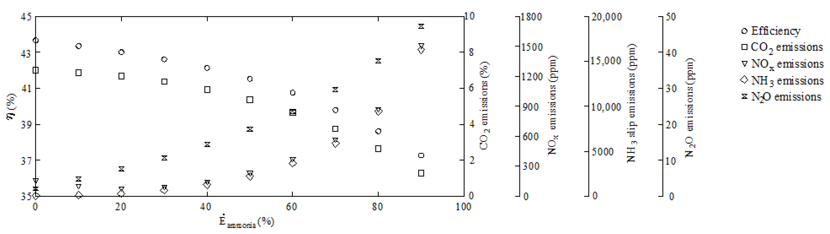
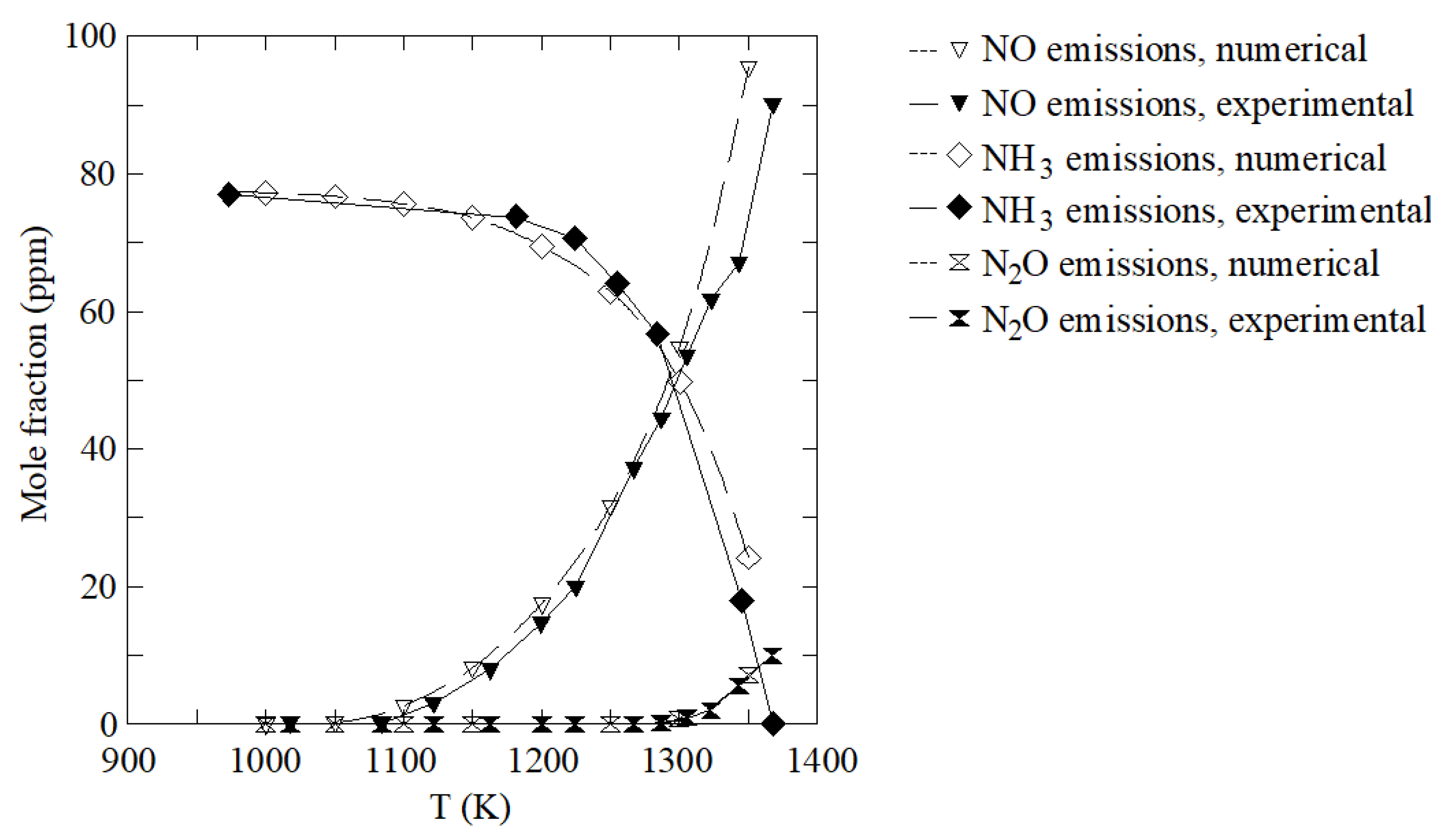
3. Results and Discussion

As indicated previously, the emissions of CO2, NOx, NH3, and N2O under percentages of power contribution from ammonia between 0 and 90% were used as data input for the MCDM model. The 10 × 4 decision matrix is shown in bold in Table 2. For illustrative purposes, this table also shows the percentage of power contribution from ammonia corresponding to each of the 10 cases analyzed, as well as the case number. The NDM is shown in Table 3. As indicated previously, all criteria are non-desirable, that is, the goal is to reduce CO2, NOx, NH3 and N2O as far as possible. Accordingly, the maximum values of these emissions are assigned a 0 value in the normalized matrix, while on the other hand, the minimum values of these emissions are assigned a maximum value of 1—Xij,min/Xj,max in the normalized matrix.
Regarding the criteria weights, nine combinations of criteria weights were analyzed to determine the sensibility of the results to these values. The weight corresponding to N2O was set to 0.05, 0.1, 0.2, 0.3, 0.4, 0.5, 0.6, 0.7, and 0.8 and the remaining to 1 was established maintaining the proportions of the other gases. The reason to analyze the effect of N2O is that it presents a high global warming effect. Although the concentration of N2O in the exhaust gas was low, it is extremely dangerous since N2O is a greenhouse gas approximately 300 times stronger than CO2 [58,59]. For this reason, its environmental damage cost is too high. The different weight combinations analyzed are shown in Table 4. Obviously, the weights in each row sum 1 (100%). This table also shows the most appropriate percentage of power contribution from ammonia for each weight combination. As can be seen in, a 20% ammonia proportion is the most appropriate option if the N2O weight is 0.05 (5%), corresponding to the first weight combination shown in Table 4. The most appropriate ammonia proportion is drastically reduced if this weight is increased. The reason is explained in Figure 1. As can be seen, Figure 1 shows that the NOx emissions first decrease and then increase with the proportion of ammonia in the fuel. Increments of NOx are promoted due to the nitrogen content of the ammonia molecule. On the other hand, NOx reductions are promoted, since ammonia leads to lower combustion temperatures than diesel oil. It is well known that the main source of NOx in diesel engines is the temperature in the combustion chamber. According to this, high ammonia proportions in the fuel can lead to low NOx emissions. These two opposing effects are responsible for the descending/ascending NOx emissions shown in Figure 1. This figure also shows a minimum NOx emissions of around 20%, which is the optimum result provided by the MCDM procedure for the first weight combination shown in Table 4. A negative aspect in the 20% optimum result is that CO2 emissions are too high, as can be seen in Figure 1.
Figure 9 provides a graphical illustration of the most appropriate ammonia percentage against the weight assigned to N2O emissions using the data indicated in Table 4. As indicated above, the N2O emissions constitute a crucial role in the decision process. The high environmental cost of N2O make these emissions too decisive. When the weight assigned to N2O is incremented the most appropriate ammonia proportion in the fuel is reduced since these emissions increase considerably. The emissions of NH3 are also increment as more ammonia is employed as a fuel. On the other hand, CO2 emissions are not too relevant in the decision-making procedure due to the lower environmental cost of CO2 in comparison to N2O, NH3 and NOx.

4. Conclusions

The goal of the present work was to illustrate the possibilities of ammonia as fuel for marine engines. The ammonia molecule, NH3, does not contain carbon and thus could lead to progress in decarbonization in the maritime field.
A dual fuel ammonia/diesel oil operation was proposed. Various ammonia-diesel oil ratios were analyzed through a CFD model. The emissions of CO2, NOx, NH3, and N2O were characterized. It was observed that, as the ammonia proportion increases, significant reductions in CO2 are obtained. Unfortunately, the use of ammonia as a fuel does not solve NOx emissions. In addition, unreacted NH3 (ammonia slip) and N2O emissions were also obtained. Due to these conflicting criteria, an MCDM method was proposed to determine the most adequate ammonia percentage, providing a formal tool to select the most appropriate ammonia proportion. Four criteria were analyzed: CO2, NOx, NH3, and N2O; and nine ammonia percentages: 0, 10, 20, 30, 40, 50, 60, 70, 80, and 90%. Several combinations of the criteria weights were treated in order to show the sensibility of the results to the values assigned to the criteria weights. Due to the important environmental adverse effects of N2O, only a maximum 20% ammonia percentage in fuel was obtained as the most appropriate option. Another issue related to excessive ammonia proportions is the NH3 and NOx emitted to the environment.
As future works, other analysis will be carried out on other type of engines. Special attention will be paid to slow engines, which will eventually lead to lower NH3 emissions. Ammonia presents a low flame temperature and slow combustion. The engine analyzed in the present work is a fast engine running at 1500 rpm. A slow engine would lead to lower ammonia slip because it would take more time to burn.

Author Contributions

Conceptualization, C.G.R., M.I.L., J.d.D.R. and A.A.; methodology, C.G.R., M.I.L., J.d.D.R. and A.A.; software, C.G.R., M.I.L., J.d.D.R. and A.A.; validation, C.G.R.; formal analysis, M.I.L.; investigation, C.G.R., M.I.L., J.d.D.R. and A.A.; resources, C.G.R.; data curation, C.G.R.; writing—original draft preparation, M.I.L.; writing—review and editing, C.G.R., J.d.D.R. and A.A.; supervision, M.I.L., J.d.D.R. and A.A.; project administration, C.G.R., M.I.L., J.d.D.R. and A.A. All authors have read and agreed to the published version of the manuscript.

Funding

This research received no external funding.

Institutional Review Board Statement

Not applicable.

Informed Consent Statement

Not applicable.

Conflicts of Interest

The authors declare no conflict of interest.

References

  1. Witkowski, J.K. Research of the effectiveness of selected methods of reducing toxic exhaust emissions of marine diesel engines. J. Mar. Sci. Eng. 2020, 8, 452. [Google Scholar] [CrossRef]
  2. Sun, X.; Liu, X.; Liang, X.; Liu, H.; Chen, Y. Research of NOx reduction on a low-speed two-stroke marine heavy-fuel oil engine. J. Energy Eng. 2021, 147, 04020088. [Google Scholar] [CrossRef]
  3. Lu, X.; Geng, P.; Chen, Y. NOx emission reduction technology for marine engine based on Tier-III: A review. J. Therm. Sci. 2020, 29, 1242–1268. [Google Scholar] [CrossRef]
  4. Varbanets, R.; Fominb, O.; Píštěk, V.; Klymenko, V.; Minchev, D.; Khrulev, A.; Zalozh, V.; Kučera, P. Acoustic method for estimation of marine low-speed engine turbocharger parameters. J. Mar. Sci. Eng. 2021, 9, 321. [Google Scholar] [CrossRef]
  5. Píštěk, V.; Kučera, P.; Fomin, O.; Lovska, A. Effective mistuning identification method of integrated bladed discs of marine engine turbochargers. J. Mar. Sci. Eng. 2020, 8, 379. [Google Scholar] [CrossRef]
  6. Napolitano, P.; Liotta, L.F.; Guido, C.; Tornatore, C.; Pantaleo, G.; Parola, V.; Beatrice, C. Insights of selective catalytic reduction technology for nitrogen oxides control in marine engine applications. Catalysts 2022, 12, 1191. [Google Scholar] [CrossRef]
  7. Winnes, H.; Fridell, E.; Moldanová, J. Effects of marine exhaust gas scrubbers on gas and particle emissions. J. Mar. Sci. Eng. 2020, 8, 299. [Google Scholar] [CrossRef]
  8. Ryu, M.; Park, P. Analysis of composite scrubber with built-in silencer for marine engines. J. Mar. Sci. Eng. 2021, 9, 962. [Google Scholar] [CrossRef]
  9. Puškár, M.; Kopas, M.; Sabadka, D.; Kliment, M.; Šoltésová, M. Reduction of the gaseous emissions in the marine diesel engine using biodiesel mixtures. J. Mar. Sci. Eng. 2020, 8, 330. [Google Scholar] [CrossRef]
  10. Lehtoranta, K.; Koponen, P.; Vesala, H.; Kallinen, K.; Maunula, T. Performance and regeneration of methane oxidation catalyst for LNG ships. J. Mar. Sci. Eng. 2021, 9, 111. [Google Scholar] [CrossRef]
  11. Jablonický, J.; Feriancová, P.; Tulík, J.; Hujo, L.; Tkáč, Z.; Kuchar, P.; Tomić, M.; Kaszkowiak, J. Assessment of technical and ecological parameters of a diesel engine in the application of new samples of biofuels. J. Mar. Sci. Eng. 2021, 10, 1. [Google Scholar] [CrossRef]
  12. dos Santos, V.A.; Pereira da Silva, P.; Serrano, L.M.V. The maritime sector and its problematic decarbonization: A systematic review of the contribution of alternative fuels. Energies 2022, 15, 3571. [Google Scholar] [CrossRef]
  13. Puškár, M. Advanced system determined for utilisation of sustainable biofuels in high-performance sport applications. Sustainability 2022, 14, 6713. [Google Scholar] [CrossRef]
  14. Lamas, M.I.; Rodriguez, C.G.; Telmo, J.; Rodriguez, J.D. Numerical analysis of emissions from marine engines using alternative fuels. Polish Marit. Res. 2015, 22, 48–52. [Google Scholar] [CrossRef] [Green Version]
  15. Chiong, M.C.; Kang, H.S.; Shaharuddin, N.M.R.; Mat, S.; Quen, L.K.; Ten, K.H.; Ong, M.C. Challenges and opportunities of marine propulsion with alternative fuels. Renew. Sustain. Energy Rev. 2021, 149, 11397. [Google Scholar] [CrossRef]
  16. Perčić, M.; Vladimir, N.; Fan, A.; Jovanović, I. Holistic energy efficiency and environmental friendliness model for short-sea vessels with alternative power systems considering realistic fuel pathways and workloads. J. Mar. Sci. Eng. 2022, 10, 613. [Google Scholar] [CrossRef]
  17. Qiu, Y.; Wei, H.; Zhou, D.; Li, J. Effect of ammonia addition on the ignition delay mechanism of methyl decanoate. J. Mar. Sci. Eng. 2022, 10, 922. [Google Scholar] [CrossRef]
  18. Shi, R.; Chen, X.; Qin, J.; Wu, P.; Jia, L. The state-of-the-art progress on the forms and modes of hydrogen and ammonia energy utilization in road transportation. Sustainability 2022, 14, 11904. [Google Scholar] [CrossRef]
  19. Liu, L.; Wu, J.; Wu, Y.; Wang, Y. Study on marine engine combustion and emissions characteristics under multi-parameter coupling of ammonia-diesel stratified injection mode. Int. J. Hydrogen Energy 2022, 48, 9881–9894. [Google Scholar] [CrossRef]
  20. Hwang, I.; Park, C.; Jeong, B. Life cycle cost analysis for Scotland short-sea ferries. J. Mar. Sci. Eng. 2023, 11, 424. [Google Scholar] [CrossRef]
  21. Bertagna, S.; Kouznetsov, I.; Braidotti, L.; Marinò, A.; Bucci, V. A rational approach to the ecological transition in the cruise market: Technologies and design compromises for the fuel switch. J. Mar. Sci. Eng. 2023, 11, 67. [Google Scholar] [CrossRef]
  22. Reusser, C.A.; Pérez Osses, J.R. Challenges for zero-emissions ship. J. Mar. Sci. Eng. 2021, 9, 1042. [Google Scholar] [CrossRef]
  23. Mallouppas, G.; Yfantis, E.A. Decarbonization in shipping industry: A review of research, technology development, and innovation proposals. J. Mar. Sci. Eng. 2021, 9, 415. [Google Scholar] [CrossRef]
  24. Kuta, K.; Przybyła, G.; Kurzydym, D.; Żmudka, A. Experimental and numerical investigation of dual-fuel CI ammonia engine emissions and after-treatment with V2O5/SiO2–TiO2 SCR. Fuel 2023, 334, 126523. [Google Scholar] [CrossRef]
  25. Ejder, E.; Arslanoğlu, Y. Evaluation of ammonia fueled engine for a bulk carrier in marine decarbonization pathways. J. Clean. Prod. 2022, 379, 134688. [Google Scholar] [CrossRef]
  26. Lanni, D.; Galloni, E.; Fontana, G.; D’Antuono, G. Assessment of the operation of an SI engine fueled with ammonia. Energies 2022, 15, 8583. [Google Scholar] [CrossRef]
  27. Seddiek, I.S.; Ammar, N.R. Technical and eco-environmental analysis of blue/green ammonia-fueled RO/RO ships. Transp. Res. Part D Transp. Environ. 2023, 114, 103547. [Google Scholar] [CrossRef]
  28. Wu, S.; Miao, B.; Chan, S.H. Feasibility assessment of a container ship applying ammonia cracker-integrated solid oxide fuel cell technology. Int. J. Hydrogen Energy 2022, 47, 27166–27176. [Google Scholar] [CrossRef]
  29. Karvounis, P.; Dantas, J.L.D.; Tsoumpris, C.; Theotokatos, G. Ship power plant decarbonisation using hybrid systems and ammonia fuel—A techno-economic–environmental analysis. J. Mar. Sci. Eng. 2022, 10, 1675. [Google Scholar] [CrossRef]
  30. Toneatti, L.; Deluca, C.; Fraleoni Morgera, A.; Piller, M.; Pozzetto, D. Waste to energy onboard cruise ships: A new paradigm for sustainable cruising. J. Mar. Sci. Eng. 2022, 10, 480. [Google Scholar] [CrossRef]
  31. Kim, K.; Roh, G.; Kim, W.; Chun, K. A preliminary study on an alternative ship propulsion system fueled by ammonia: Environmental and economic assessments. J. Mar. Sci. Eng. 2020, 8, 183. [Google Scholar] [CrossRef] [Green Version]
  32. Huang, J.; Fan, H.; Xu, X.; Liu, Z. Life cycle greenhouse gas emission assessment for using alternative marine fuels: A very large crude carrier (VLCC) case study. J. Mar. Sci. Eng. 2022, 10, 1969. [Google Scholar] [CrossRef]
  33. Rodríguez, C.G.; Lamas, M.I.; Rodríguez, J.D.; Abbas, A. Possibilities of ammonia as both fuel and NOx reductant in marine engines: A numerical study. J. Mar. Sci. Eng. 2022, 10, 43. [Google Scholar] [CrossRef]
  34. Rodriguez, C.G.; Lamas, M.I.; Rodriguez, J.D.; Abbas, A. Analysis of the pre-injection system of a marine diesel engine through multiple-criteria decision making and artificial neural networks. Polish Marit. Res. 2021, 28, 88–96. [Google Scholar] [CrossRef]
  35. Lamas Galdo, M.I.; Castro-Santos, L.; Rodríguez Vidal, C.G. Selection of an appropriate pre-injection pattern in a marine diesel engine through a multiple-criteria decision making approach. Appl. Sci. 2020, 10, 2482. [Google Scholar] [CrossRef] [Green Version]
  36. di Sarli, V.; Cammarota, F.; Salzano, E.; di Benedetto, A. Explosion behavior of ammonia and ammonia/methane in oxygen-enriched air. Process Saf. Prog. 2017, 36, 368–371. [Google Scholar] [CrossRef]
  37. Lamas, M.I.; Rodriguez, C.G. NOx reduction in diesel-hydrogen engines using different strategies of ammonia injection. Energies 2019, 12, 1255. [Google Scholar] [CrossRef] [Green Version]
  38. Lamas, M.I.; Rodriguez, C.G. Numerical model to analyze NOx reduction by ammonia injection in diesel-hydrogen engines. Int. J. Hydrogen Energy 2017, 42, 26132–26141. [Google Scholar] [CrossRef]
  39. Lamas Galdo, M.I.; Castro-Santos, L.; Rodriguez Vidal, C.G. Numerical analysis of NOx reduction using ammonia injection and comparison with water injection. J. Mar. Sci. Eng. 2020, 8, 109. [Google Scholar] [CrossRef] [Green Version]
  40. Ra, Y.; Reitz, R.D. A reduced chemical kinetic model for IC engine combustion simulations with primary reference fuels. Combust. Flame 2008, 155, 713–738. [Google Scholar] [CrossRef]
  41. Yang, H.; Krishnan, S.R.; Srinivasan, K.K.; Midkiff, K.C. Modeling of NOx emissions using a super-extended Zel’dovich mechanism. In Proceedings of the ICEF03 2003 Fall Technical Conference of the ASME Internal Combustion Engine Division, Erie, PA, USA, 7–10 September 2003. [Google Scholar] [CrossRef]
  42. Miller, J.A.; Glarborg, P. Modeling the formation of N2O and NO2 in the thermal DeNOx process. Springer Ser. Chem. Phys. 1996, 61, 318–333. [Google Scholar]
  43. Mathieu, O.; Petersen, E.L. Experimental and modeling study on the high-temperature oxidation of ammonia and related NOx chemistry. Combust. Flame 2015, 162, 554–570. [Google Scholar] [CrossRef] [Green Version]
  44. Hulgaard, T.; Dam-Johansen, K. Homogeneous nitrous oxide formation and destruction under combustion conditions. React. Kinet. Catal. 1993, 39, 1342–1354. [Google Scholar] [CrossRef]
  45. Xiao, H.; Chen, A.; Guo, Y.; Zhang, L.; Zhang, M.; Deng, X.; Li, J.; Ying, W. Auto-ignition delay characteristics of ammonia substitution on methane. Processes 2022, 10, 2214. [Google Scholar] [CrossRef]
  46. Chiong, M.C.; Chong, C.T.; Ng, J.H.M.; Mashruk, S.; Chong, W.W.F.; Samiran, N.A.; Mong, G.R.; Valera-Medina, A. Advancements of combustion technologies in the ammonia-fuelled engines. Energy Convers. Manag. 2021, 244, 114460. [Google Scholar] [CrossRef]
  47. Cardoso, J.S.; Silva, V.; Rocha, R.C.; Hall, M.J.; Costa, M.; Eusébio, D. Ammonia as an energy vector: Current and future prospects for low-carbon fuel applications in internal combustion engines. J. Clean. Prod. 2021, 296, 126562. [Google Scholar] [CrossRef]
  48. Pham, Q.; Park, S.; Agarwal, A.K.; Park, S. Review of dual-fuel combustion in the compression-ignition engine: Spray, combustion, and emission. Energy 2022, 250, 123778. [Google Scholar] [CrossRef]
  49. Kurien, C.; Mittal, M. Review on the production and utilization of green ammonia as an alternate fuel in dual-fuel compression ignition engines. Energy Convers. Manag. 2022, 251, 114990. [Google Scholar] [CrossRef]
  50. Vinogradova, I.; Podvezko, V.; Zavadskas, E. The recalculation of the weights of criteria in MCDM methods using the Bayes approach. Symmetry 2018, 10, 205. [Google Scholar] [CrossRef] [Green Version]
  51. Lamas, M.I.; Castro-Santos, L.; Rodriguez, C.G. Optimization of a multiple injection system in a marine diesel engine through a multiple-criteria decision-making approach. J. Mar. Sci. Eng. 2020, 8, 946. [Google Scholar] [CrossRef]
  52. Gürbüz, H.; Demirtürk, S.; Akçay, I.H.; Akçay, H. Effect of port injection of ethanol on engine performance, exhaust emissions and environmental factors in a dual-fuel diesel engine. Energy Environ. 2021, 32, 784–802. [Google Scholar] [CrossRef]
  53. Gürbüz, H.; Akçay, H.; Aldemir, M.; Akçay, I.H.; Topalcı, U. The effect of euro diesel-hydrogen dual fuel combustion on performance and environmental-economic indicators in a small UAV turbojet engine. Fuel 2021, 306, 121735. [Google Scholar] [CrossRef]
  54. Methodenhandbuch Zum Bundesverkehrswegeplan 2030; FE-Projekt-Nr.: 97.358/2015; Bundesministerium für Verkehr und Digitale Infrastruktur: Berlin, Germany, 2016; Available online: https://www.bi-nordzulauf-ko.de/wp-content/uploads/2019/09/bvwp-2030-methodenhandbuch.pdf (accessed on 10 February 2023).
  55. AEA Technology Environment. Damages per Tonne Emission of PM2.5, NH3, SO2, NOx and VOCs from Each EU25 Member State (excluding Cyprus) and Surrounding Seas; AEA Technology Environment: Didcot, UK.
  56. Rodriguez, C.G.; Lamas, M.I.; Rodriguez, J.D.; Caccia, C. Analysis of the pre-injection configuration in a marine engine through several MCDM techniques. Brodogradnja 2021, 72, 1–17. [Google Scholar] [CrossRef]
  57. Krishnan, A.R. Past efforts in determining suitable normalization methods for multi-criteria decision-making: A short survey. Front. Big Data 2022, 5, 990699. [Google Scholar] [CrossRef]
  58. Dimitriou, P.; Javaid, R. A review of ammonia as a compression ignition engine fuel. Int. J. Hydrogen Energy 2020, 45, 7098–7118. [Google Scholar] [CrossRef]
  59. Valeria-Medina, A.; Hatem, F.; Azad, A.; Dedoussi, I.; de Joannon, M.; Fernandes, R.X.; Glarborg, P.; Hashemi, H.; He, X.; Mashruk, S.; et al. Review on ammonia as a potential fuel: From synthesis to economics. Energy Fuels 2021, 35, 6964–7029. [Google Scholar] [CrossRef]
Figure 1. Efficiency and emissions of CO2, NOx, NH3, and N2O under dual fuel ammonia/diesel in the MAN D2840LE V10 engine. Adapted from [33].
Jmse 11 00689 g001
Figure 2. (a) Engine analyzed in the present work. (b) Section of each cylinder at TDC (top dead center) position.
Jmse 11 00689 g002
Figure 3. Computational mesh. (a) 3D view at BDC. (b) AA section at BDC. (c) AA section at TDC.
Jmse 11 00689 g003
Figure 4. Pressure at 100% load experimentally and numerically measured. Operation under diesel combustion without ammonia.
Jmse 11 00689 g004
Figure 5. Consumption and emissions of CO2 and NOx experimentally and numerically measured. Operation under diesel combustion without ammonia.
Jmse 11 00689 g005
Figure 6. Computational mesh employed to reproduce the experiments of Hulgaard and Kim Dam-Johansen [44].
Jmse 11 00689 g006
Figure 7. Comparison between the numerical results obtained with the CFD code and the experiments of Hulgaard and Kim Dam-Johansen [44]. Adapted with permission from Ref. [44], copyright owner: John Willey and Sons.
Jmse 11 00689 g007
Figure 8. (a) Mass flow of ammonia fuel against the percentage of power contribution from ammonia. (b) Mass flow of diesel oil fuel against the percentage of power contribution from ammonia.
Jmse 11 00689 g008
Figure 9. Most appropriate percentage of power contribution from ammonia against the weight assigned to N2O emissions.
Jmse 11 00689 g009
Table 1. Mesh size and time-step sensitivity analysis.
MeshTime Step (s)SFC Error (%)CO2 Error (%)NOx Error (%)
Mesh 11.1 × 10−53.94.36.1
Mesh 21.5 × 10−53.84.25.9
Mesh 21.1 × 10−53.84.15.8
Mesh 20.8 × 10−53.84.15.8
Mesh 31.1 × 10−53.84.15.7
Table 2. Decision matrix.
Case
(i)
E ˙ a m m o n i a
(%)
Criterion (j)
j = 1 CO2 (%)j = 2 NOx (ppm)j = 3 NH3 (ppm)j = 4 N2O (ppm)
106.99157.317.141.72
2106.87101.7132.144.38
3206.6777.70214.267.19
4306.3793.22648.8410.33
5405.93144.921262.6813.95
6505.37234.442217.1818.18
7604.64369.083677.3323.30
8703.74564.715883.8029.34
9802.63866.799426.5137.28
10901.281498.8516,288.7446.95
Table 3. Normalized decision matrix.
Case
(i)
E ˙ a m m o n i a
(%)
Criterion (j)
j = 1 CO2j = 2 NOxj = 3 NH3j = 4 N2O
100.000.901.000.96
2100.020.931.000.91
3200.050.950.990.85
4300.090.940.960.78
5400.150.900.920.70
6500.230.840.860.61
7600.340.750.770.50
8700.470.620.640.38
9800.620.420.420.21
10900.820.000.000.00
Table 4. Most appropriate percentage of power contribution from ammonia for different combinations of weights.
WeightsMost Appropriate Alternative
CO2NOxNH3N2O E ˙ a m m o n i a (%)
0.2000.2500.5000.0520
0.1890.2370.4740.110
0.1680.2100.4210.20
0.1470.1840.3680.30
0.1260.1580.3160.40
0.1050.1310.2630.50
0.0840.1050.2100.60
0.0630.0790.1580.70
0.0420.0530.1050.80
Disclaimer/Publisher’s Note: The statements, opinions and data contained in all publications are solely those of the individual author(s) and contributor(s) and not of MDPI and/or the editor(s). MDPI and/or the editor(s) disclaim responsibility for any injury to people or property resulting from any ideas, methods, instructions or products referred to in the content.

