
Influence of Soil Plug on the Seismic Response of Bucket Foundations in Liquefiable Seabed


Abstract
:1. Introduction
2. Numerical Method
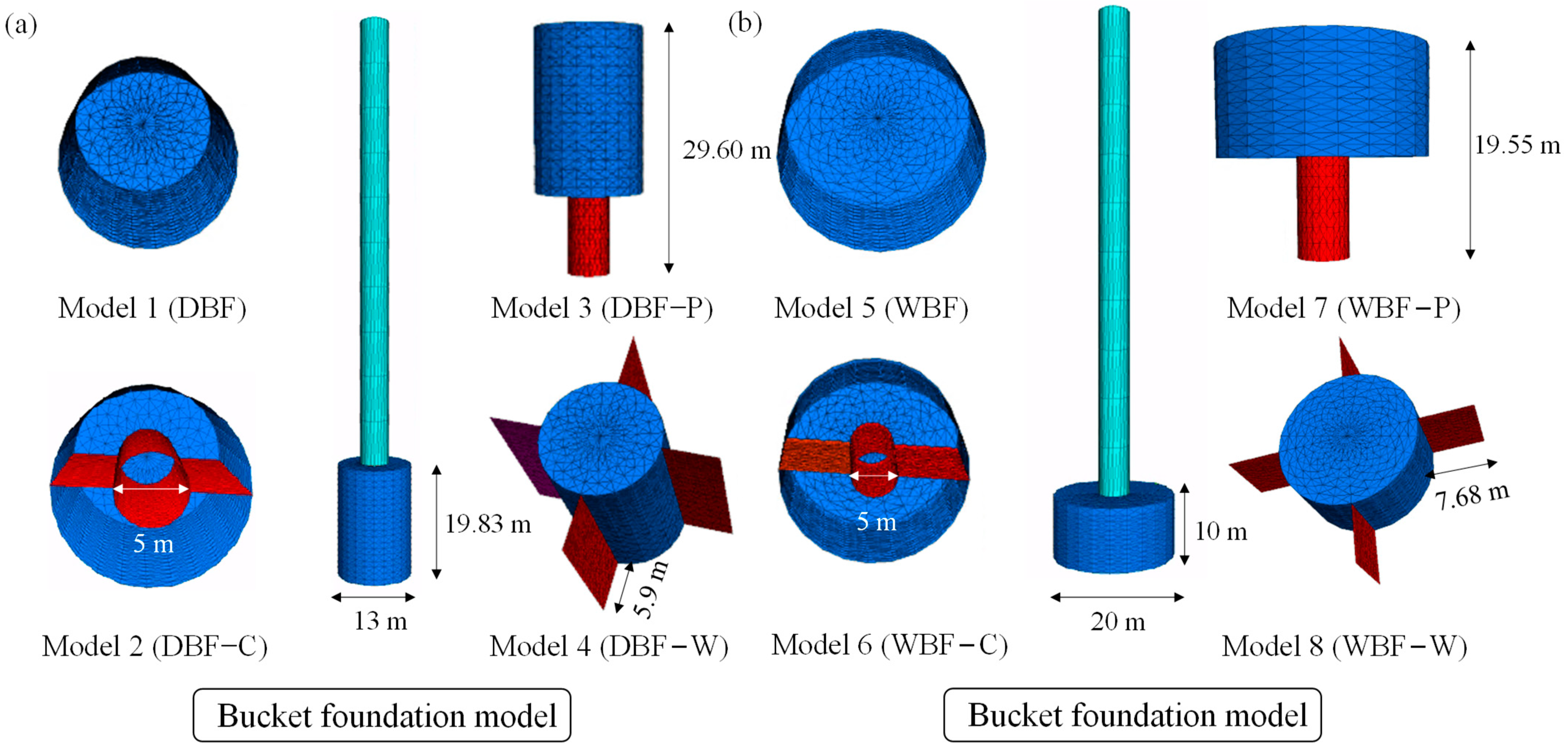
2.1. The OWT Model
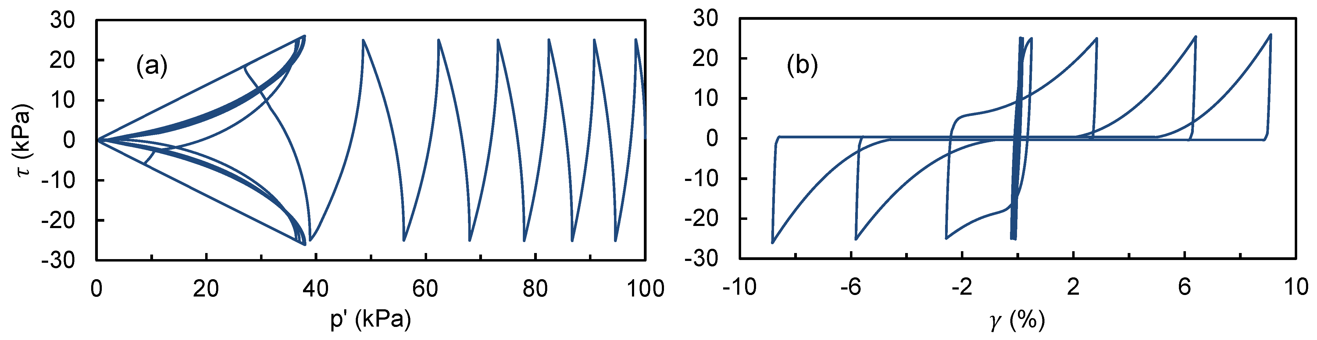
2.2. Seabed Soil Specification
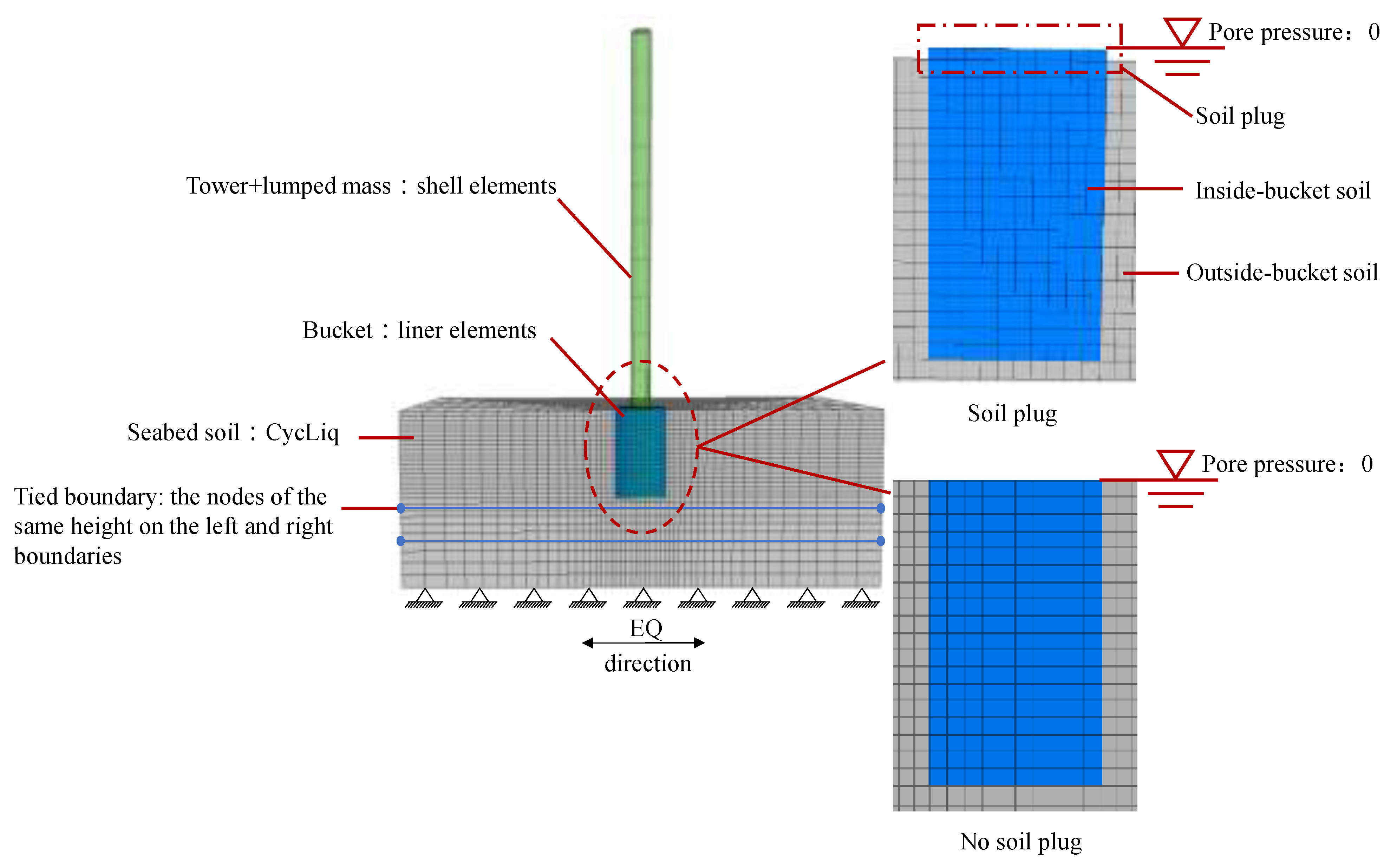
2.3. Numerical Simulation Program
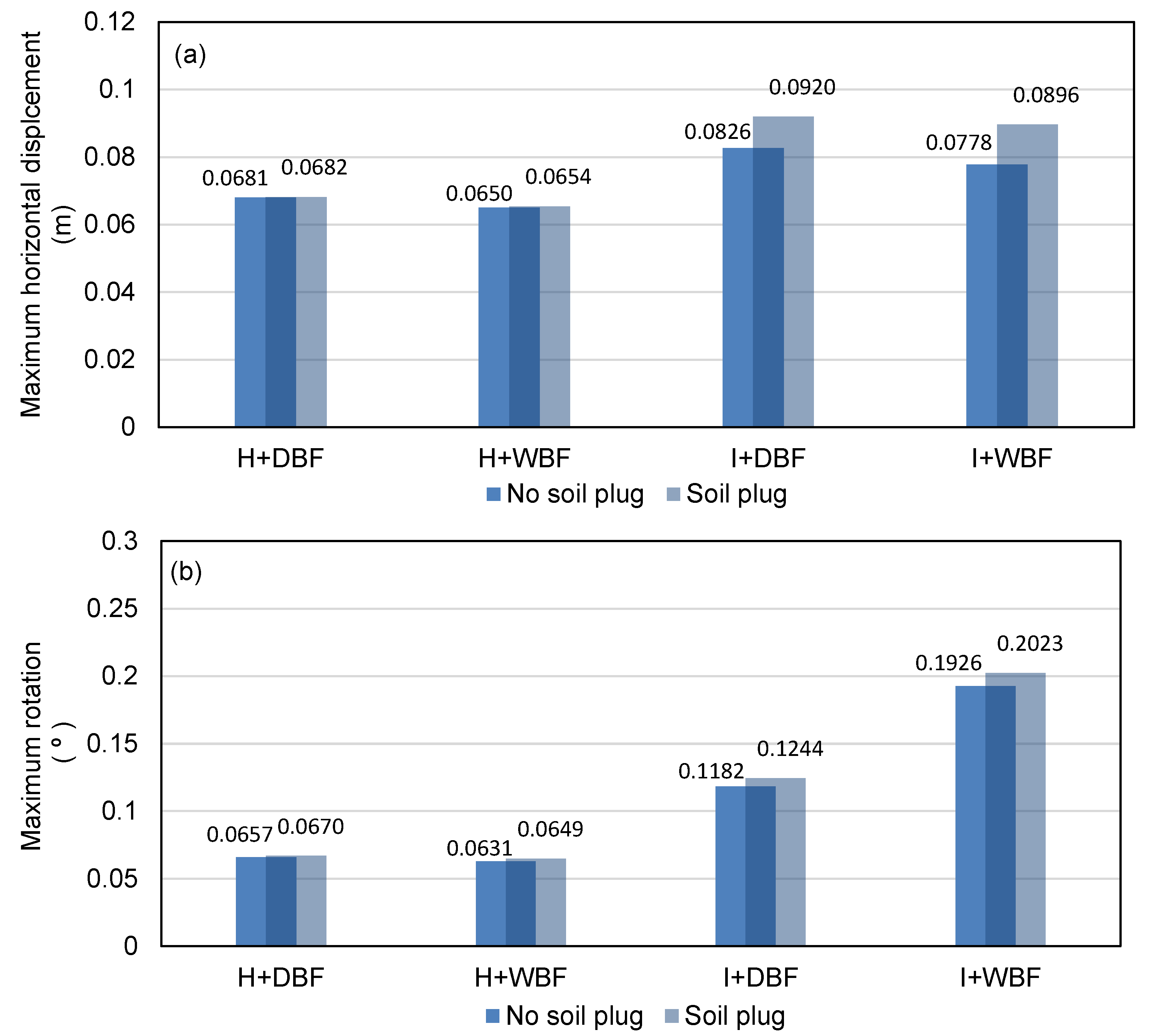
3. Influence of Soil Plug on OWT Bucket Foundation Response
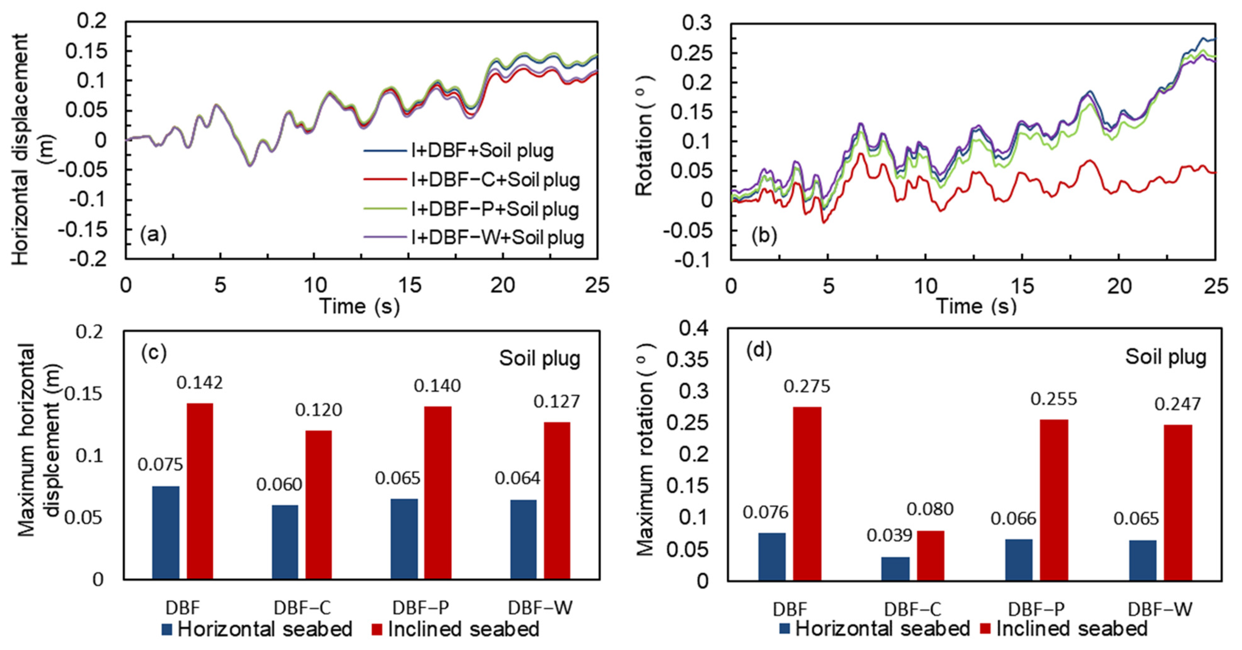
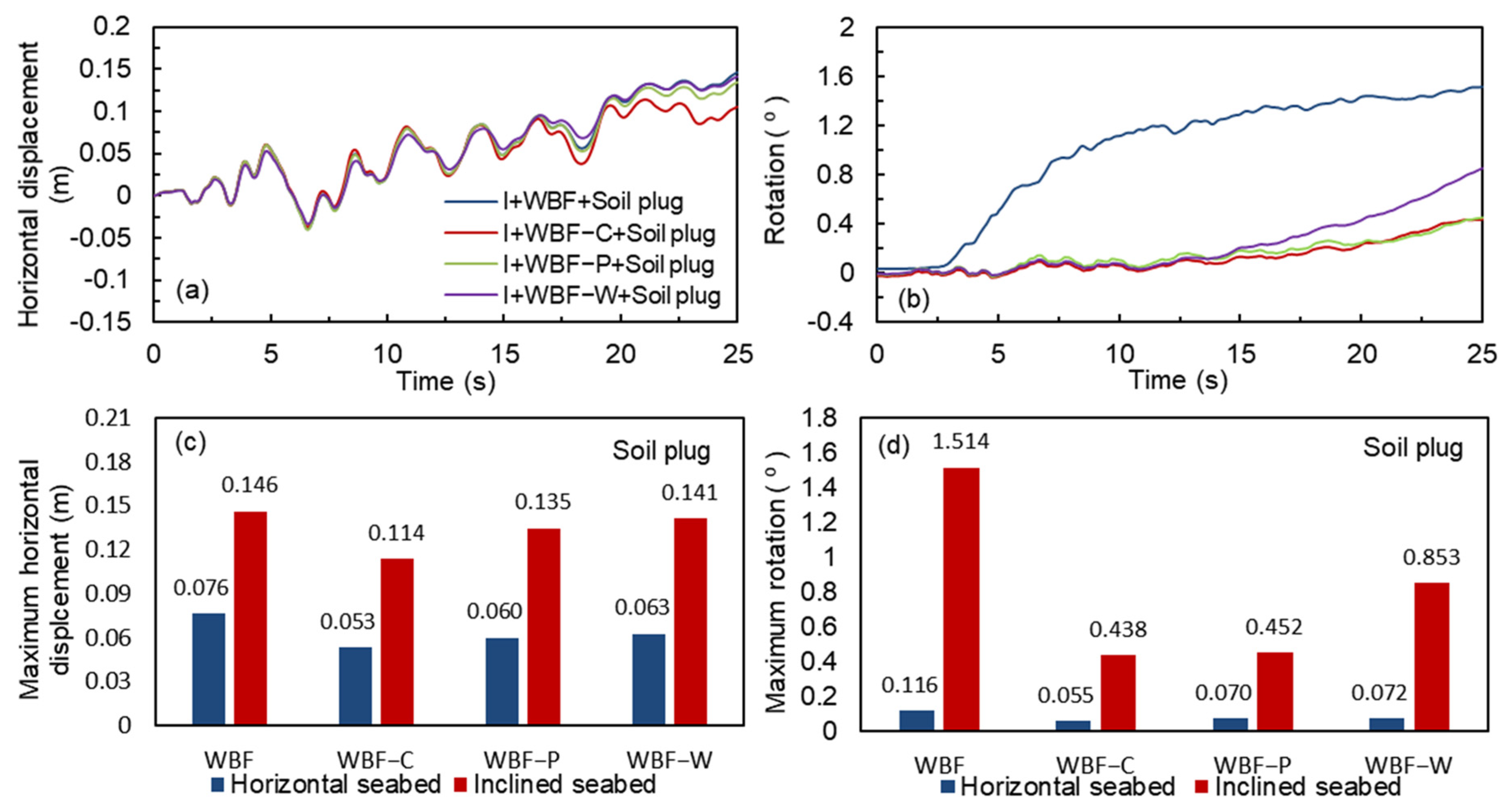
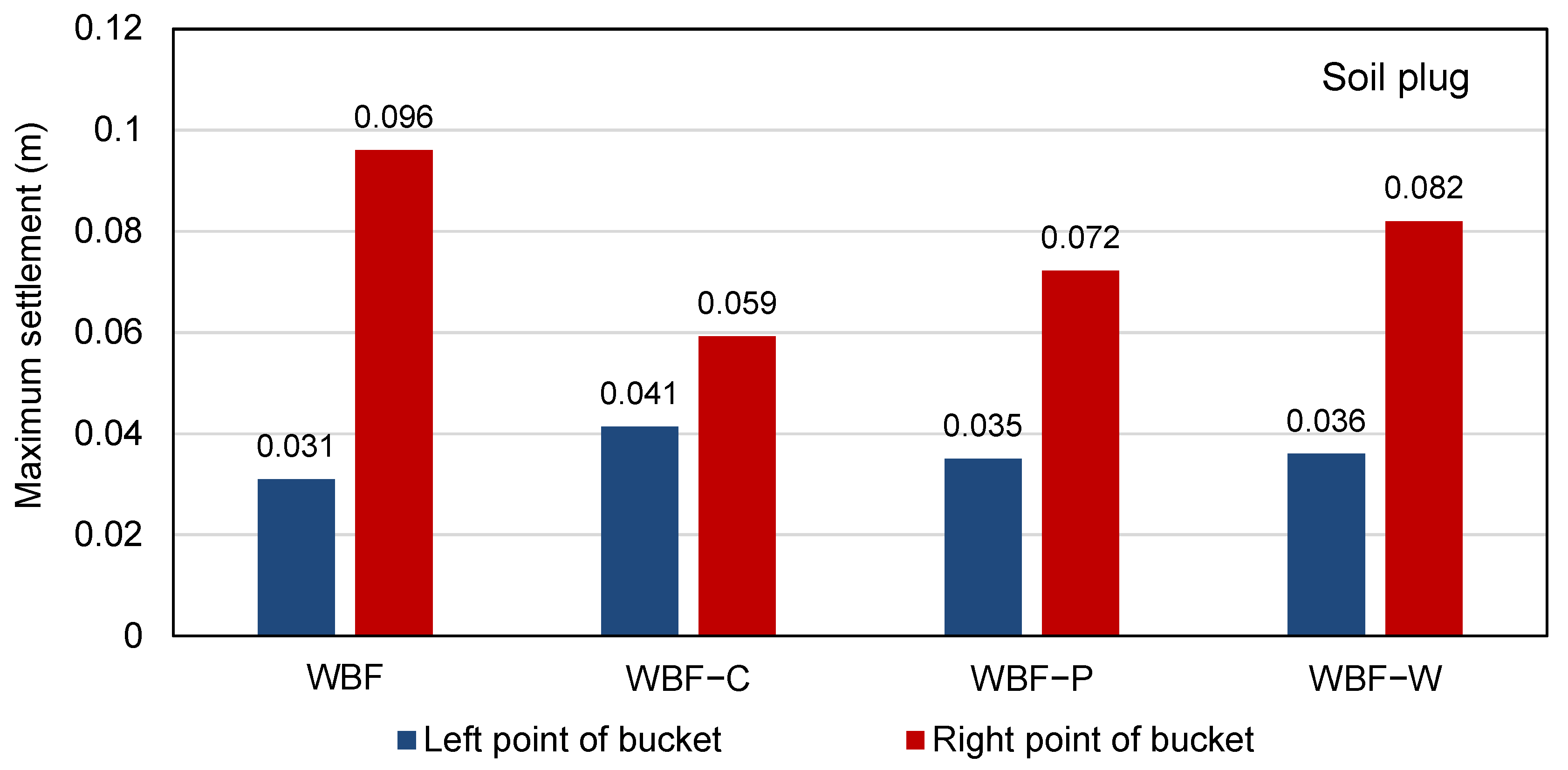
4. Seismic Response of Bucket Foundation with Different Reinforcement Types
5. Influence of Soil Plug Removal on Bucket Foundation Response
6. Conclusions
- (1)
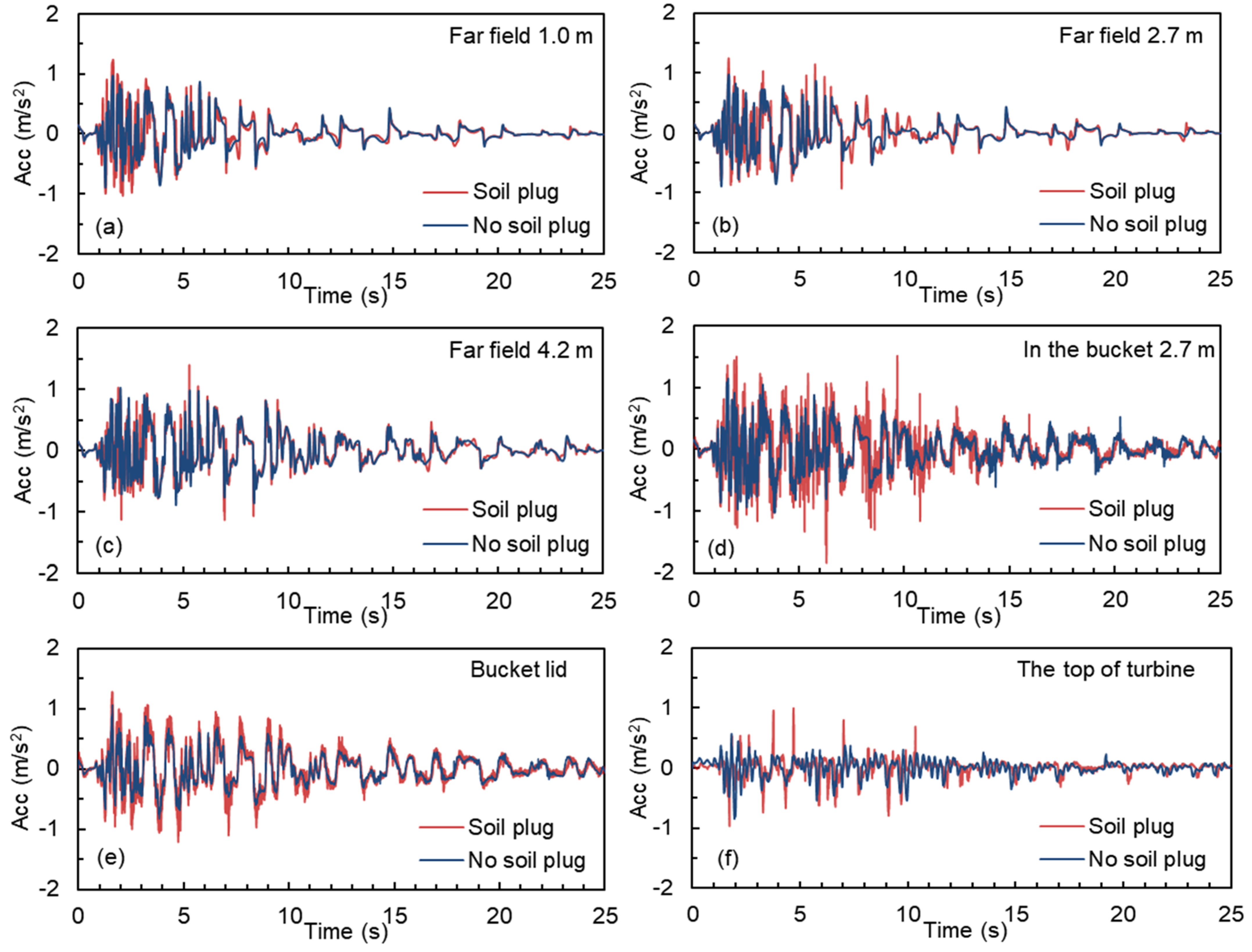
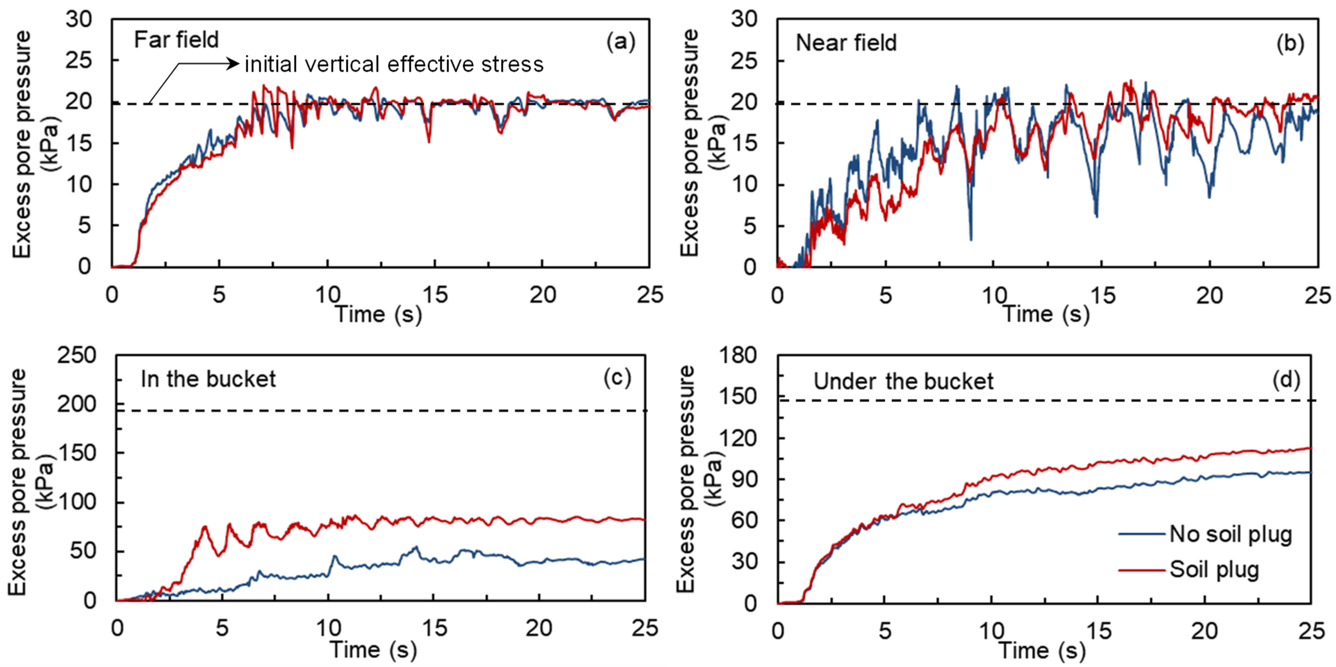
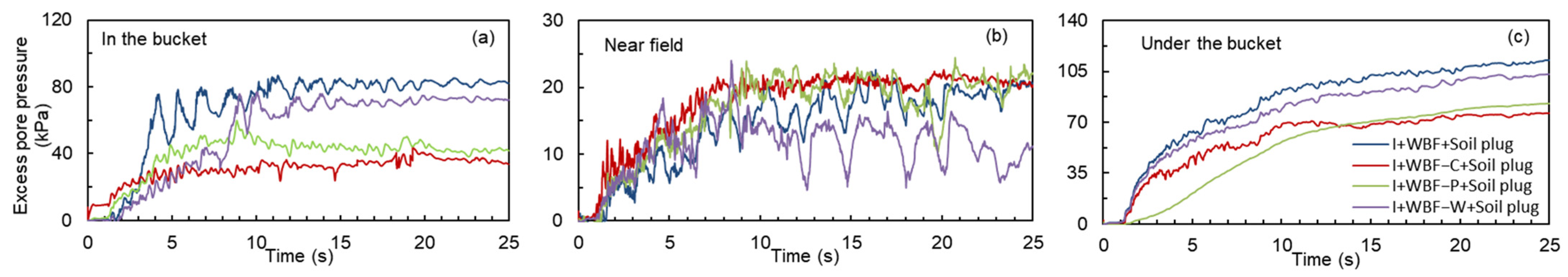
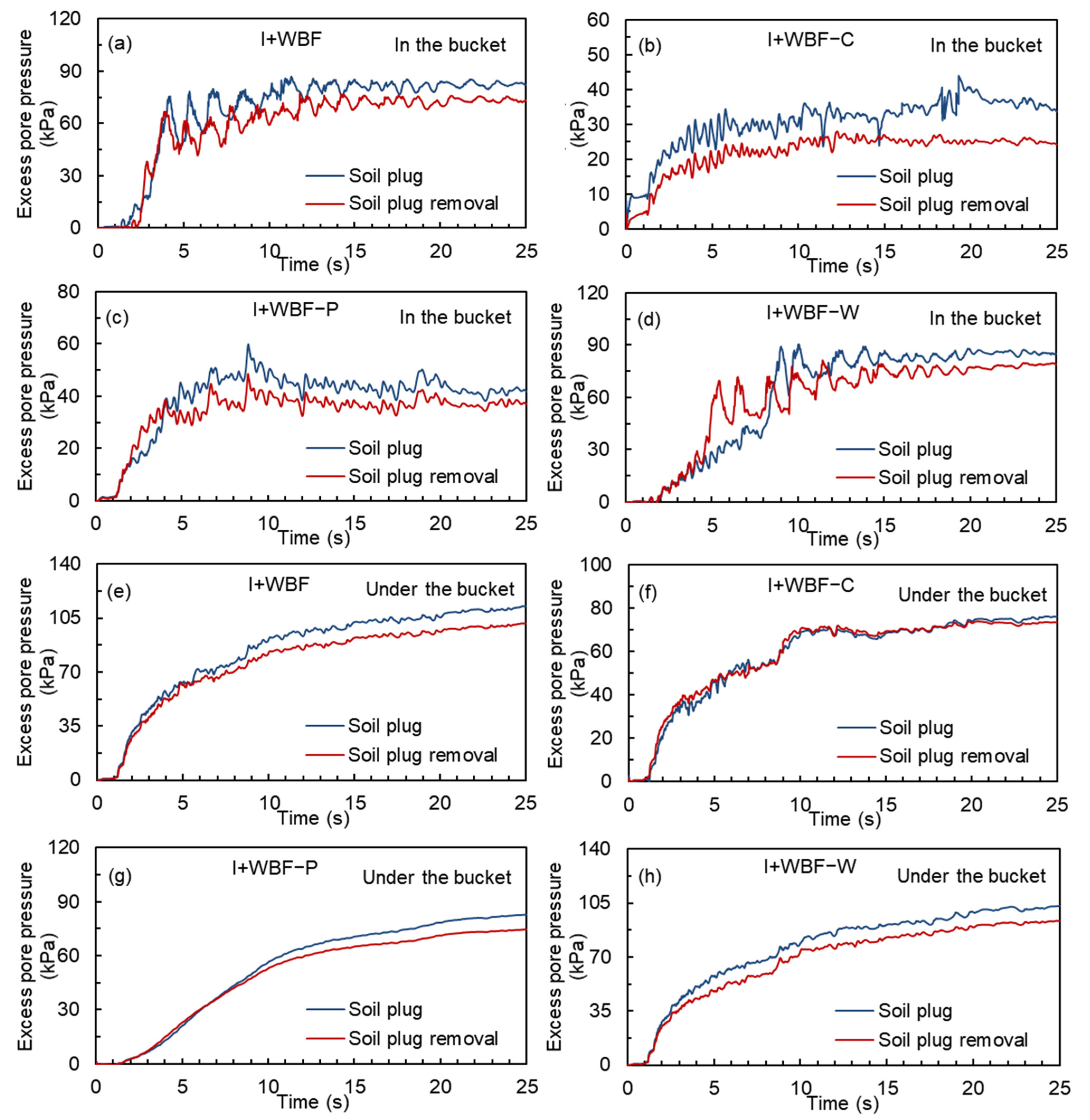
- The presence of soil plug causes slight amplification of acceleration for the inside-bucket soil, bucket and turbine compared with the case without soil plug. It causes significant increase in the accumulation of excess pore pressure in soil inside and under the bucket, and causes stronger fluctuation in the excess pore pressure of near field soil due to the stronger dynamic interaction between bucket and soil.
- (2)
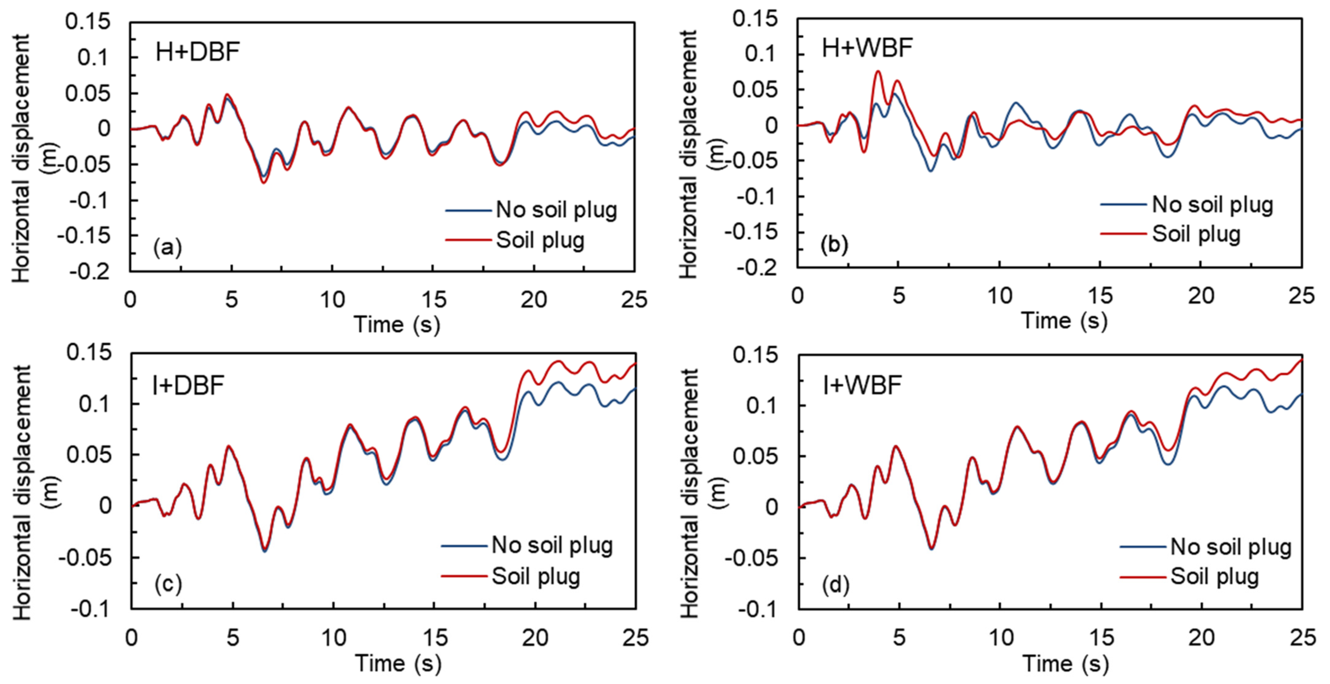
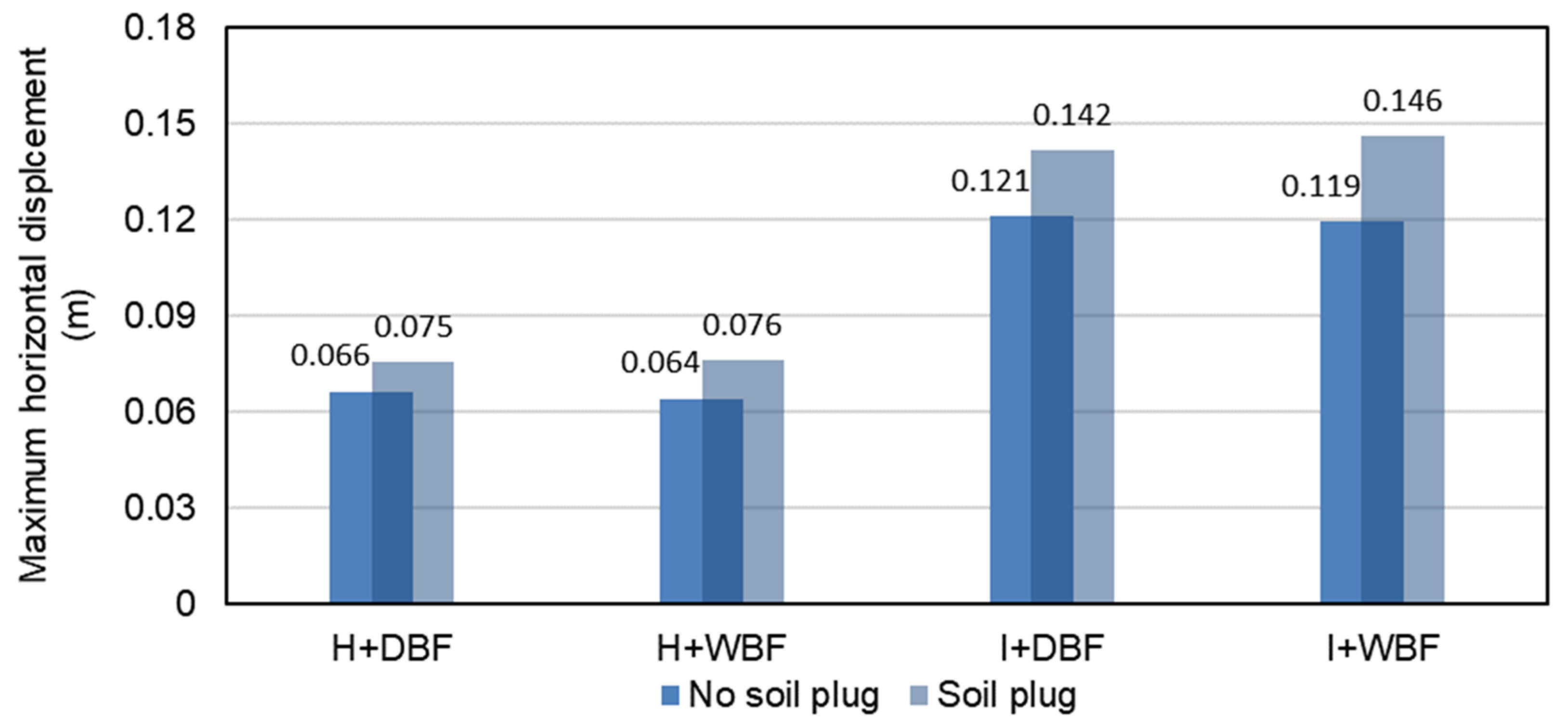
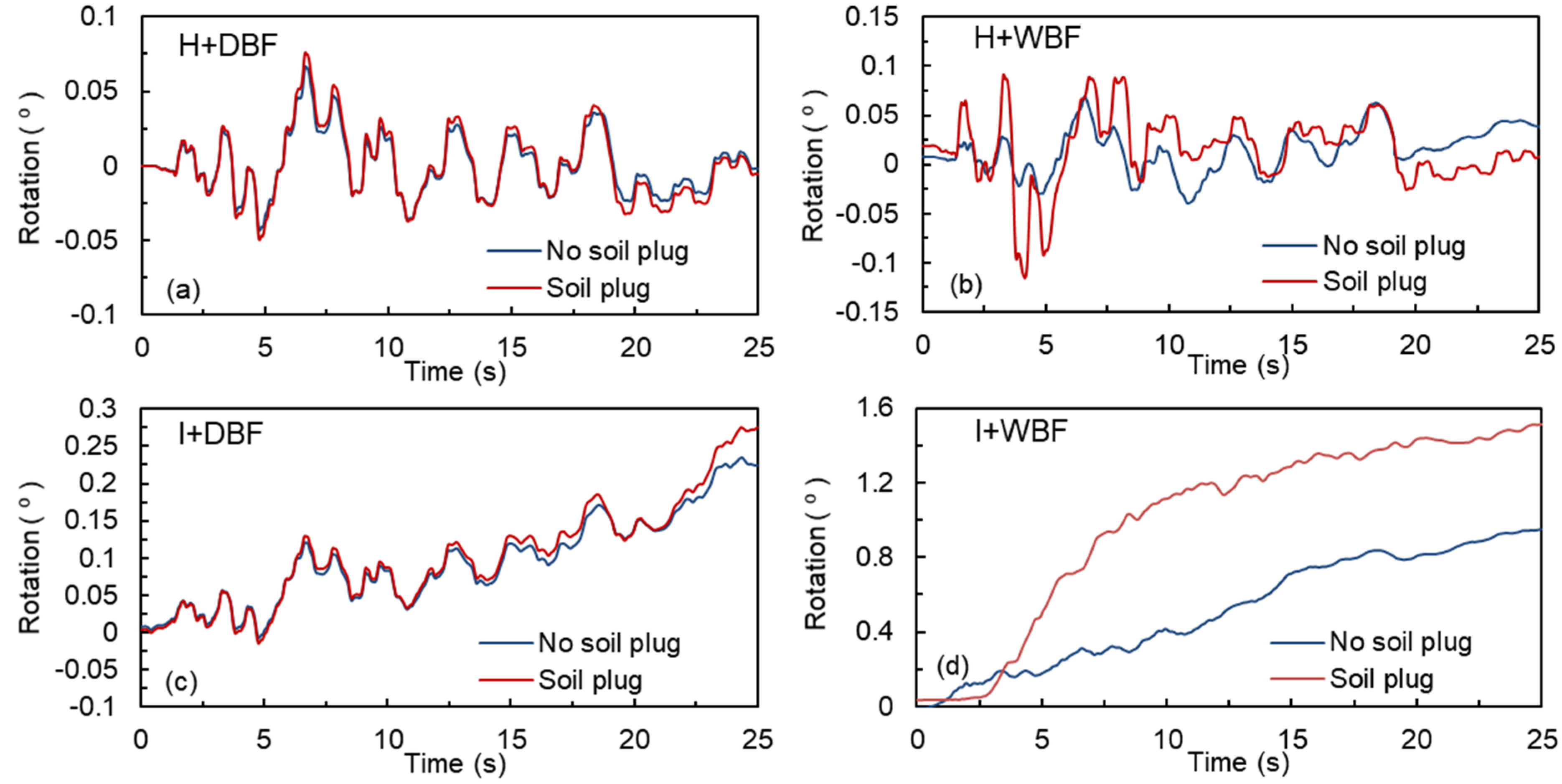
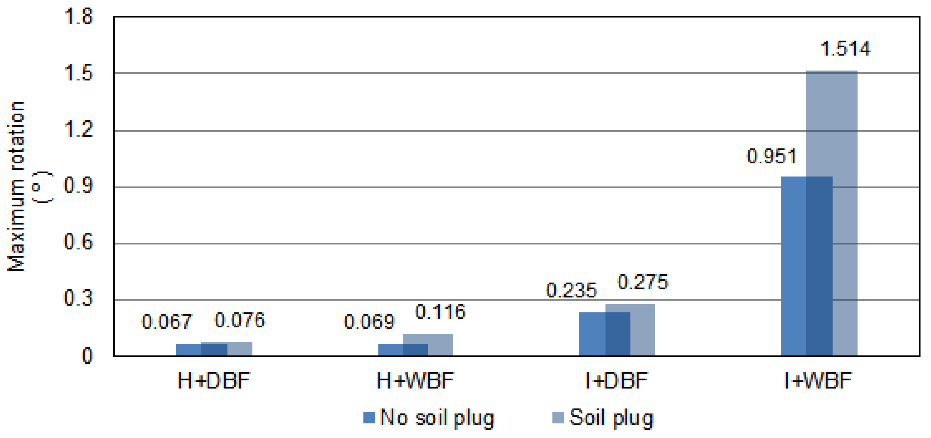
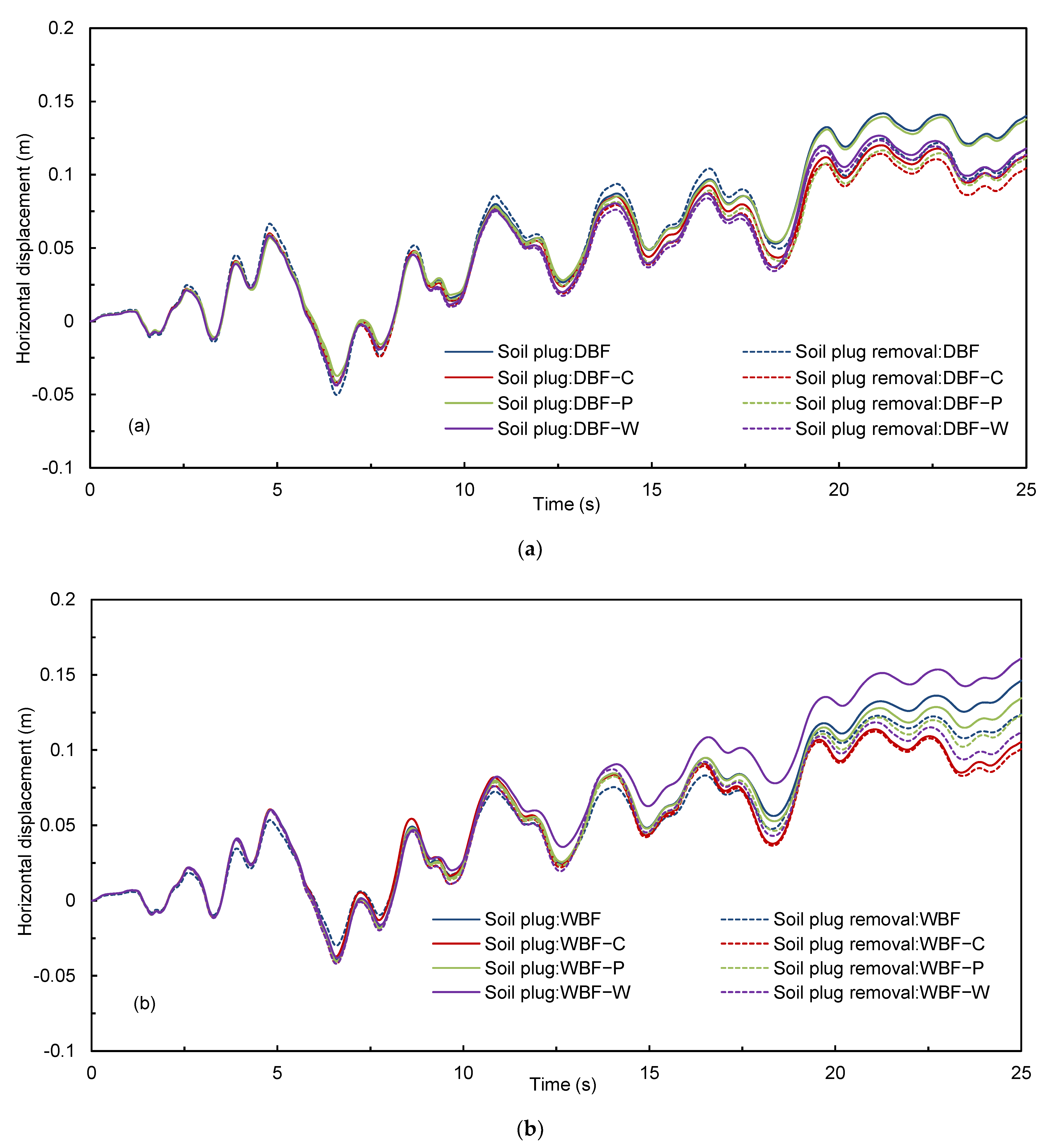
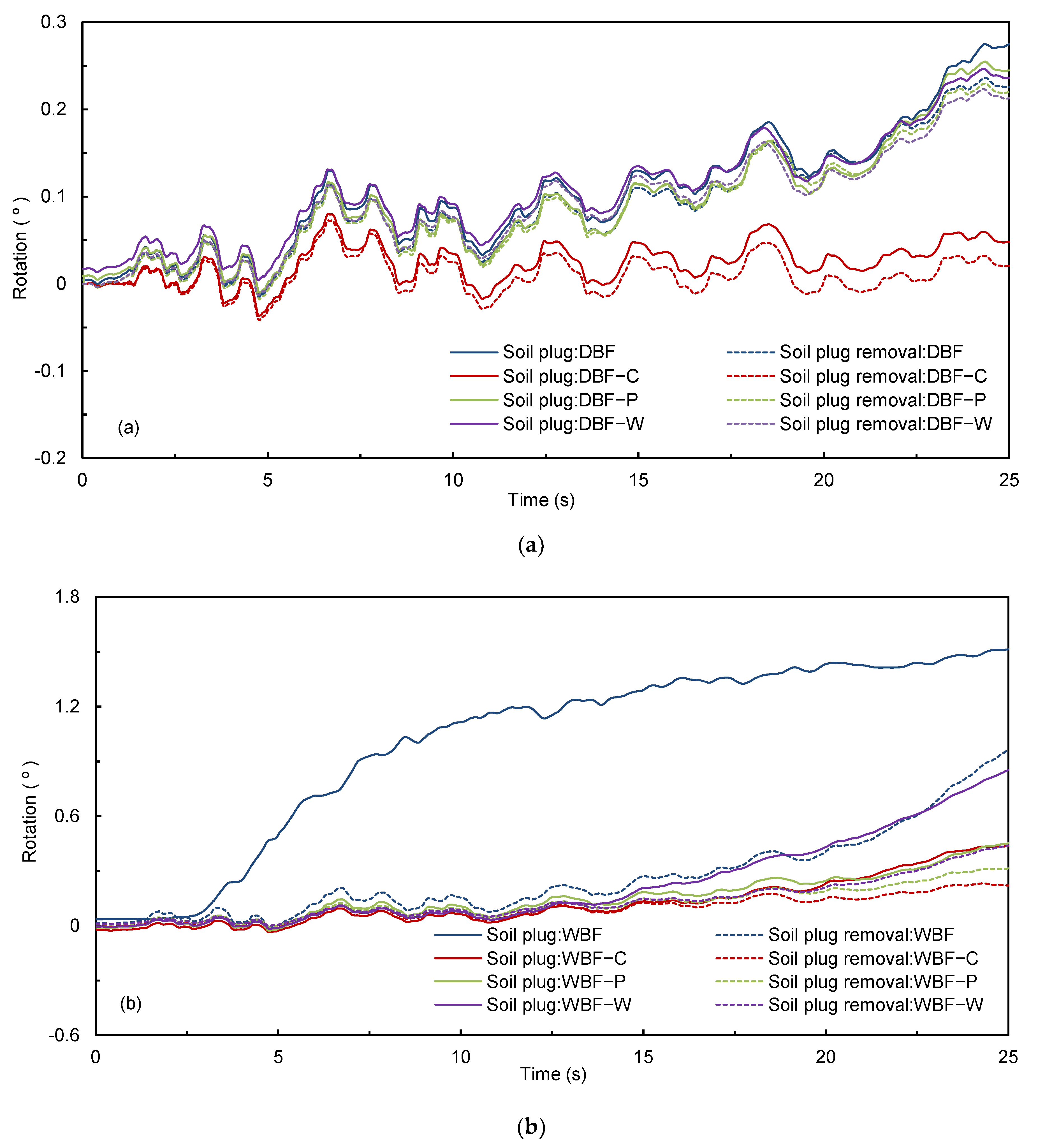
- The existence of soil plug has a significant unfavorable influence on the seismic performance of OWT on bucket foundations, especially in inclined liquefiable seabed, resulting in up to a 60% increase in bucket rotation for the wide bucket foundation model, which needs to be considered in the seismic design of OWT. The influence of soil plug is more significant in relatively loose seabed compared with in denser seabed.
- (3)
- The application of reinforcement methods, including adding an inner compartment, outer wings and inner pile, can improve the seismic performance of OWT on bucket foundation by limiting excess pore pressure generation in near field soil and subsequently reducing bucket displacement, nonuniform settlement and rotation. The application of an inner compartment is found to be the most effective reinforcement type to reduce the seismic response of the bucket.
- (4)
- Soil plug removal can have a favorable influence on the seismic response of OWT bucket foundation, which can alleviate the undesired influence of the soil plug, and should be adopted when possible. A combination of removing the soil plug and using reinforced bucket foundations can significantly improve the seismic performance of bucket foundation-based OWTs.
Author Contributions
Funding
Institutional Review Board Statement
Informed Consent Statement
Data Availability Statement
Conflicts of Interest
References
- Kaldellis, J.K.; Apostolou, D.; Kapsali, M.; Kondili, E. Environmental and social footprint of offshore wind energy. Comparison with onshore counterpart. Renew Energy 2016, 92, 543–556. [Google Scholar] [CrossRef]
- Simonova, M.D.; Zakharov, V.E. Statistical Analysis of Development Trends in Global Renewable Energy. Mgimo Rev. Int. Relat. 2016, 48, 214–220. [Google Scholar] [CrossRef]
- Swan, S.; Hadjian, A.H. The 1986 North Palm Springs Earthquake: Effects on Power Facilities; No. EPRI-NP-5607; EQE, Inc.: San Francisco, CA, USA; Bechtel Power Corp.: Norwalk, CA, USA, 1988. [Google Scholar]
- Prowell, I.; Veers, P. Assessment of Wind Turbine Seismic Risk: Existing Literature and Simple Study of Tower Moment Demand. Sandia National Laboratories (SNL), Albuquerque, NM, and Livermore, CA (United States). 2009. Available online: https://www.osti.gov/biblio/983699 (accessed on 7 February 2023). [CrossRef] [Green Version]
- Butt, U.A.; Ishihara, T. Seismic Load Evaluation of Wind Turbine Support Structures Considering Low Structural Damping and Soil Structure Interaction. Eur. Wind. Energy Assoc. Annu. Event 2012, 4, 16–19. [Google Scholar]
- Ritschel, U.; Warnke, I.; Kirchner, J.; Meussen, B. Wind turbines and earthquakes. In Proceedings of the 2nd World Wind Energy Conference, Cape Town, South Africa, 24 November 2003. [Google Scholar]
- Asareh, M.A.; Schonberg, W.; Volz, J. Effects of seismic and aerodynamic load interaction on structural dynamic response of multi-megawatt utility scale horizontal axis wind turbines. Renew Energy 2016, 86, 49–58. [Google Scholar] [CrossRef]
- Risi, R.D.; Bhattacharya, S.; Goda, K. Seismic performance assessment of monopile-supported offshore wind turbines using unscaled natural earthquake records. Soil Dyn. Earthq. Eng. 2018, 109, 154–172. [Google Scholar] [CrossRef]
- Kaynia, A.M. Seismic considerations in design of offshore wind turbines. Soil Dyn. Earthq. Eng. 2019, 124, 399–407. [Google Scholar] [CrossRef]
- Cui, C.Y.; Meng, K.; Wu, Y.J.; Chapman, D.; Liang, Z.M. Dynamic response of pipe pile embedded in layered visco-elastic media with radial inhomogeneity under vertical excitation. Geomech. Eng. 2018, 16, 609–618. [Google Scholar]
- Cui, C.Y.; Liang, Z.M.; Xu, C.S.; Xin, Y.; Wang, B.L. Analytical solution for horizontal vibration of end-bearing single pile in radially heterogeneous saturated soil. Appl. Math. Model. 2023, 116, 65–83. [Google Scholar] [CrossRef]
- Meng, K.; Cui, C.Y.; Liang, Z.M.; Li, H.J.; Pei, H.F. A new approach for longitudinal vibration of a large-diameter floating pipe pile in visco-elastic soil considering the three-dimensional wave effects. Comput. Geotech. 2020, 128, 103840. [Google Scholar] [CrossRef]
- Gao, B.; Zhu, W.X.; Zhang, Q.; Ye, G.L. Response of suction bucket foundation subjected to wind and earthquake loads on liquefiable sandy seabed. Soil Dyn. Earthq. Eng. 2022, 160, 107338. [Google Scholar] [CrossRef]
- Wen, F. Developments and characteristics of offshore wind farms in China. Adv. New Renew. Enengy 2016, 4, 152–158. [Google Scholar]
- Shang, W.M. Study on engineering geological conditions of Xinghua Bay offshore wind farm in Fuqing. Low Carbon World 2017, 22, 61–62. [Google Scholar]
- Qu, X.Q.; Zhang, Z.T.; Hu, J.; Wang, R.; Zhang, J.M. Centrifuge shaking table tests on offshore wind turbine bucket foundation in mildly inclined liquefiable seabed. Soil Dyn. Earthq. Eng. 2021, 151, 107012. [Google Scholar] [CrossRef]
- Senpere, D.; Auvergne, G.A. Suction anchor piles-a proven alternative to driving or drilling. In Proceedings of the Offshore Technology Conference, Houston, TX, USA, 3–6 May 1982. [Google Scholar]
- Tjelta, T.I. Geotechnical experience from the installation of the Europipe jacket with bucket foundations. In Proceedings of the Offshore Technology Conference, Houston, TX, USA, 1–4 May 1995. [Google Scholar]
- Allersma, H.G.B.; Plenevaux, F.J.A.; Wintgens, J.F. Simulation of suction pile installation in sand in a geocentrifuge. In Proceedings of the Seventh International Offshore and Polar Engineering Conference, Honolulu, HI, USA, 1 January 1997. [Google Scholar]
- Ding, H.Y.; Liu, Z.Y.; Chen, X. Model tests on soil plug formation in suction anchor for silty clay. J. Geotech. Eng. 2001, 169, 214–223. [Google Scholar]
- Tran, M.N.; Randolph, M.F.; Airey, D.W. Installation of suction caissons in sand with silt layers. J. Geotech. Geoenviron. Eng. 2007, 133, 1183–1191. [Google Scholar] [CrossRef]
- Wang, H. Research on Penetration Resistance and Uplift Bearing Capacity Evolution of Suction Caisson and Soil Plug Removal. Ph.D. Thesis, Tsinghua University, Beijing, China, 2022. [Google Scholar]
- Yu, H.; Zeng, X.W.; Lian, J.J. Seismic behavior of offshore wind turbine with suction caisson foundation. In Proceedings of the 2014 Geo-Congress, Atlanta, Georgia, 23–26 February 2014. [Google Scholar]
- Wang, X.F.; Zeng, X.W.; Yu, H.; Wang, H.J. Centrifuge modeling of offshore wind turbine with bucket foundation under earthquake loading. In Proceedings of the International Foundations Congress and Equipment Expo (IFCEE) 2015, San Antonio, Texas, 17–21 March 2015. [Google Scholar]
- Olalo, L.T.; Choo, Y.W.; Bae, K.T. Influence of the Skirt on the Seismic Response of Bucket Foundations for Offshore Wind Tower Using Dynamic Centrifuge Model Tests. In Proceedings of the ASME 2016 35th International Conference on Ocean, Offshore and Arctic Engineering, Busan, Republic of Korea, 19–24 June 2016. [Google Scholar]
- Wang, R.; Liu, X.; Zhang, J.M. Numerical analysis of the seismic inertial and kinematic effects on pile bending moment in liquefiable soils. Acta Geotech. 2017, 12, 773–791. [Google Scholar] [CrossRef]
- Wang, X.F.; Zeng, X.W.; Yang, X.; Li, J.L. Seismic response of offshore wind turbine with hybrid monopile foundation based on centrifuge modelling. Appl. Energy 2019, 235, 1335–1350. [Google Scholar] [CrossRef]
- Li, X.Y.; Zeng, X.W.; Yu, X.; Wang, X.F. Seismic response of a novel hybrid foundation for offshore wind turbine by geotechnical centrifuge modeling. Renew Energy 2021, 172, 1404–1416. [Google Scholar] [CrossRef]
- Zayed, M. Experimental and Numerical Seismic Response of Offshore Wind Turbines Supported on Bucket Foundations. Ph.D. Dissertation, University Of California San Diego, San Diego, CA, USA, 2022. [Google Scholar]
- Asheghabadi, M.S.; Jebeli, A.J. Seismic Behavior of Suction Caisson Foundations. Int. J. Geotech. Geol. Eng. 2019, 13, 30–36. [Google Scholar]
- Gao, B.; Ye, G.L.; Zhang, Q.; Xie, Y.; Yan, B. Numerical simulation of suction bucket foundation response located in liquefiable sand under earthquakes. Ocean Eng. 2021, 235, 109394. [Google Scholar] [CrossRef]
- Wang, X.F.; Ma, C.L.; Li, J.L. Seismic response of suction bucket foundation for offshore wind turbines: A parametric study. Ocean Eng. 2022, 257, 111570. [Google Scholar] [CrossRef]
- Esfeh, P.K.; Kaynia, A.M. Earthquake response of monopiles and caissons for Offshore Wind Turbines founded in liquefiable soil. Soil Dyn. Earthq. Eng. 2020, 136, 106213. [Google Scholar] [CrossRef]
- Ueda, K.; Uzuoka, R.; Iai, S.; Okamura, T. Centrifuge model tests and effective stress analyses of offshore wind turbine systems with a suction bucket foundation subject to seismic load. Soils Found. 2020, 60, 1546–1569. [Google Scholar] [CrossRef]
- Kourkoulis, R.S.; Lekkakis, P.C.; Gelagoti, F.M.; Kaynia, A.M. Suction caisson foundations for offshore wind turbines subjected to wave and earthquake loading: Effect of soil-foundation interface. Geotechnique 2014, 64, 171–185. [Google Scholar] [CrossRef] [Green Version]
- Zhang, P.Y.; Xiong, K.P.; Ding, H.Y.; Le, C.H. Anti-liquefaction characteristics of composite bucket foundations for offshore wind turbines. J. Renew Sustain. Energy 2014, 6, 053102. [Google Scholar] [CrossRef]
- Eslami, A.; Ghorbani, A. Seismic response of offshore wind turbines supported on Monopiles and Suction Buckets: Numerical modelling and soft computing study. Soil Dyn. Earthq. Eng. 2022, 159, 107284. [Google Scholar] [CrossRef]
- Liu, H.; Wu, W.B.; Jiang, G.S.; El Naggar, M.H.; Mei, G.X.; Liang, R.Z. Influence of soil plug effect on the vertical dynamic response of large diameter pipe piles. Ocean Eng. 2018, 157, 13–25. [Google Scholar] [CrossRef]
- Lehane, B.; Powrie, W.; Doherty, J. Centrifuge model tests on piled footings in clay for offshore wind turbines. In Proceedings of the Second International Symposium on Frontiers in offshore Geotechnics (ISFOG), University of Western Australia, Perth, Australia, 8–10 November 2010. [Google Scholar]
- Li, D.Y.; Zhang, Y.K.; Feng, L.Y.; Gao, Y.F. Capacity of modified suction caissons in marine sand under static horizontal loading. Ocean Eng. 2015, 102, 1–16. [Google Scholar] [CrossRef]
- Wang, X.F.; Yang, X.; Zeng, X.W. Seismic centrifuge modelling of suction bucket foundation for offshore wind turbine. Renew Energy 2017, 114, 1013–1022. [Google Scholar] [CrossRef]
- Faizi, K.; Faramarzi, A.; Dirar, S.; Chapman, D. Finite Element Modelling of the Performance of Hybrid Foundation Systems for Offshore Wind Turbines; Springer: Berlin/Heidelberg, Germany, 2019. [Google Scholar]
- Zhang, P.Y.; Li, J.Y.; Le, C.H.; Ding, H.Y. Seismic responses of two bucket foundations for offshore wind turbines based on shaking table tests. Renew Energy 2022, 187, 1100–1117. [Google Scholar] [CrossRef]
- Chen, W.Y.; Jiang, Y.J.; Xu, L.Y.; Liu, C.; Chen, G.X.; Wang, P.G. Seismic response of hybrid pile-bucket foundation supported offshore wind turbines located in liquefiable soils. Ocean Eng. 2023, 269, 113519. [Google Scholar] [CrossRef]
- Dimmock, P.; Clukey, E.; Randolph, M.F.; Murff, D.; Gaudin, C. Hybrid Subsea Foundations for Subsea Equipment. J. Geotech. Geoenviron. Eng. 2013, 139, 2182–2192. [Google Scholar] [CrossRef]
- Fu, D.F.; Bienen, B.; Gaudin, C.; Cassidy, M. Undrained capacity of a hybrid subsea skirted mat with caissons under combined loading. Can. Geotech. J. 2014, 51, 934–949. [Google Scholar] [CrossRef]
- Kim, J.H.; Kim, S.; Kim, D.S. Bearing capacity of hybrid suction foundation on sand with loading direction via centrifuge model test. Jpn. Geotech. Soc. Spec. Publ. 2016, 2, 1339–1342. [Google Scholar] [CrossRef]
- Chen, X.G.; Ma, Q.S.; Jiang, Y.K.; Xu, J.P. A offshore wind turbine suction bucket foundation for soil plug removal. Shandong province, China. CN105926661A, 7 September 2016. [Google Scholar]
- An, J.B.; Liu, J.L.; Wang, C.H.; LIU, J.Q. A bucket foundation capable of reducing soil plug. Anhui province, China. CN109306705B, 27 November 2020. [Google Scholar]
- He, B.; Shen, K.M.; Qi, H.F. A sub-cabin bucket foundation with anti-soil plug and reverse grouting. Zhejiang province, China. CN213390204U, 8 June 2021. [Google Scholar]
- Itasca Consulting Group Inc. Fast Language Analysis of Continua in 3 Dimensions, Version 5.0, User’s manual. Minneapolis, Minnesota. 2012. Available online: https://www.itascacg.com/software/flac3d (accessed on 7 February 2023).
- Qu, X.Q.; Wang, R.; Zhang, J.M. Centrifuge and Numerical Simulation of Offshore Wind Turbine Suction Bucket Foundation Seismic Response in Inclined Liquefiable seabed. In Conference on Performance-Based Design in Earthquake. Geotechnical Eingineering; Springer: Berlin/Heidelberg, Germany, 2022; pp. 1215–1221. [Google Scholar]
- Wang, R.; Zhang, J.M.; Wang, G. A unified plasticity model for large post-liquefaction shear deformation of sand. Comput. Geotech. 2014, 59, 54–66. [Google Scholar] [CrossRef]
- Zou, Y.X.; Zhang, J.M.; Wang, R. Seismic analysis of stone column improved liquefiable seabed using a plasticity model for coarse-grained soil. Comput. Geotech. 2020, 125, 103690. [Google Scholar] [CrossRef]
- He, B.; Zhang, J.M.; Li, W.; Wang, R. Numerical analysis of LEAP centrifuge tests on sloping liquefiable seabed: Influence of dilatancy and post-liquefaction shear deformation. Soil Dyn. Earthquake Eng. 2020, 137, 106288. [Google Scholar] [CrossRef]
- Liu, H.X.; Zhang, J.M.; Zhang, X.D.; Wang, R. Seismic performance of block-type quay walls with liquefiable calcareous sand backfill. Soil Dyn. Earthq. Eng. 2020, 132, 106092. [Google Scholar] [CrossRef]
- Zhu, T.; Wang, R.; Zhang, J.M. Evaluation of various seismic response analysis methods for underground structures in saturated sand. Tunn. Undergr. Space Technol. 2021, 110, 103803. [Google Scholar] [CrossRef]
- Li, Y.Y.; Luo, C.; Zhang, J.M.; Liu, F.; Wang, R. Rayleigh Wave-Shear Wave Coupling Mechanism for Large Lateral Deformation in Level Liquefiable seabed. Comput. Geotech. 2022, 143, 104631. [Google Scholar] [CrossRef]
- Wang, R. Influence of vertical ground motion on the seismic response of underground structures and underground-aboveground structure systems in liquefiable seabed. Tunn. Undergr. Space Technol. 2022, 122, 104351. [Google Scholar] [CrossRef]
- Li, Y.Y.; Wang, R.; Zhang, J.M. A stepwise artificial boundary condition for wave propagation in elasto-plastic media. Soil Dyn. Earthq. Eng. 2023, 165, 107733. [Google Scholar] [CrossRef]
- Yang, S.L.; Li, A.L.; Qi, J.F. Experimental study on bucket foundation during penetration by suction. J. Geotech. Eng. 2003, 14, 236–238. [Google Scholar]
- Guo, Z.; Jeng, D.S.; Guo, W.; He, R. Simplified approximation for seepage effect on penetration resistance of suction caissons in sand. Ships Offshore Struct. 2017, 12, 980–990. [Google Scholar] [CrossRef]
- Tran, M.N. Installation of suction caissons in dense sand and the influence of silt and cemented layers. Ph.D. Thesis, School of Civil Engineering, University of Sydney, Sydney, Australia, 2005. [Google Scholar]
- Liu, X. Research on Seismic Response of Pile Group in Liquefiable Ground. Ph.D. Thesis, Tsinghua University, Beijing, China, 2018. [Google Scholar]
- Du, J.; Ding, H.Y.; Liu, J.H.; Zhang, C. Research on boundary selection of soil of bucket foundation with finite element analysis. Ocean Technol. 2005, 24, 109–113. [Google Scholar]
- Yang, M.; Luo, R.P.; Li, W.C. Numerical study on accumulated deformation of laterally loaded monopiles used by offshore wind turbine. Bull. Eng. Geol. Environ. 2018, 77, 911–921. [Google Scholar] [CrossRef]
- Chaloulos, Y.K.; Tsiapas, Y.Z.; Bouckovalas, G.D. Seismic analysis of a model tension leg supported wind turbine under seabed liquefaction. Ocean Eng. 2021, 238, 109706. [Google Scholar] [CrossRef]
- GB 17741-2005; Evaluation of Seismic Safety for Engineering Sites. Standards Press of China: Beijing, China, 2005.
- GB50011-2010; Code for Seismic Design of Buildings. Architecture & Building Press: Beijing, China, 2010.
- GB 18306-2015; Seismic Ground Motion Parameter Zonation Map of China. Standards Press of China: Beijing, China, 2015.
- Hesar, M. Geotechnical design of the Barracuda and Caratinga suction anchors. In Proceedings of the Offshore Technology Conference, Houston, TX, USA, 5–8 May 2003. [Google Scholar]
- Peire, K.; Nonneman, H.; Bosschem, E. Gravity base foundations for the thornton bank offshore wind farm. Terraet Aqua. 2009, 115, 19–29. [Google Scholar]


| Model ID | Bucket Diameter | Bucket Height | Reinforcement Type |
|---|---|---|---|
| Model 1 (DBF) | 13 | 19.83 | Single Bucket |
| Model 2 (DBF-C) | 13 | 19.83 | Inner-Compartment Bucket |
| Model 3 (DBF-P) | 13 | 19.83 | Pile–Bucket |
| Model 4 (DBF-W) | 13 | 19.83 | Outer-Wing Bucket |
| Model 5 (WBF) | 20 | 10 | Single Bucket |
| Model 6 (WBF-C) | 20 | 10 | Inner-Compartment Bucket |
| Model 7 (WBF-P) | 20 | 10 | Pile–Bucket |
| Model 8 (WBF-W) | 20 | 10 | Outer-Wing Bucket |
| h | M | ||||||||||||
|---|---|---|---|---|---|---|---|---|---|---|---|---|---|
| 200 | 0.006 | 1.7 | 0.45 | 30 | 0.6 | 40 | 0.05 | 1.1 | 8.0 | 1.3 | 0.023 | 0.837 | 0.7 |
| Soil Outside the Bucket | Soil Inside the Bucket | |||||
|---|---|---|---|---|---|---|
| Dry Density ρd (kg/m3) | Permeability Coefficient k (cm/s) | Void Ratio e | Dry Density ρd (kg/m3) | Permeability Coefficient k (cm/s) | Void Ratio e | |
| Soil 1 | 1.54 × 10³ | 1.5 × 10⁻² | 0.717 | 1.49 × 10³ | 3 × 10⁻² | 0.782 |
| Soil 2 | 1.64 × 10³ | 5.0 × 10⁻³ | 0.620 | 1.58 × 10³ | 1.0 × 10⁻² | 0.677 |
| Simulation Number | Seabed Rotation | Relative Density of Inside-Bucket Soil | Relative Density of Outside-Bucket Soil | Soil Plug | Bucket Model |
|---|---|---|---|---|---|
| 1 | Horizontal | 50% | 50% | No | 1 (DBF) |
| 2 | Horizontal | 30% | 50% | 0.7 m | 1 (DBF) |
| 3 | Horizontal | 50% | 50% | No | 5 (WBF) |
| 4 | Horizontal | 30% | 50% | 0.36 m | 5 (WBF) |
| 5 | Inclined | 50% | 50% | No | 1 (DBF) |
| 6 | Inclined | 30% | 50% | 0.7 m | 1 (DBF) |
| 7 | Inclined | 50% | 50% | No | 5 (WBF) |
| 8 | Inclined | 30% | 50% | 0.36 m | 5 (WBF) |
| 9 | Horizontal | 80% | 80% | No | 1 (DBF) |
| 10 | Horizontal | 62.4% | 80% | 0.7 m | 1 (DBF) |
| 11 | Horizontal | 80% | 80% | No | 5 (WBF) |
| 12 | Horizontal | 62.4% | 80% | 0.36 m | 5 (WBF) |
| 13 | Inclined | 80% | 80% | No | 1 (DBF) |
| 14 | Inclined | 62.4% | 80% | 0.7 m | 1 (DBF) |
| 15 | Inclined | 80% | 80% | No | 5 (WBF) |
| 16 | Inclined | 62.4% | 80% | 0.36 m | 5 (WBF) |
| 17 | Horizontal | 30% | 50% | 0.7 m | 2 (DBF-C) |
| 18 | Horizontal | 30% | 50% | 0.7 m | 3 (DBF-P) |
| 19 | Horizontal | 30% | 50% | 0.7 m | 4 (DBF-W) |
| 20 | Horizontal | 30% | 50% | 0.36 m | 6 (WBF-C) |
| 21 | Horizontal | 30% | 50% | 0.36 m | 7 (WBF-P) |
| 22 | Horizontal | 30% | 50% | 0.36 m | 8 (WBF-W) |
| 23 | Inclined | 30% | 50% | 0.7 m | 2 (DBF-C) |
| 24 | Inclined | 30% | 50% | 0.7 m | 3 (DBF-P) |
| 25 | Inclined | 30% | 50% | 0.7 m | 4 (DBF-W) |
| 26 | Inclined | 30% | 50% | 0.36 m | 6 (WBF-C) |
| 27 | Inclined | 30% | 50% | 0.36 m | 7 (WBF-P) |
| 28 | Inclined | 30% | 50% | 0.36 m | 8 (WBF-W) |
| 29 | Horizontal | 30% | 50% | Removed | 1 (DBF) |
| 30 | Horizontal | 30% | 50% | Removed | 2 (DBF-C) |
| 31 | Horizontal | 30% | 50% | Removed | 3 (DBF-P) |
| 32 | Horizontal | 30% | 50% | Removed | 4 (DBF-W) |
| 33 | Horizontal | 30% | 50% | Removed | 5 (WBF) |
| 34 | Horizontal | 30% | 50% | Removed | 6 (WBF-C) |
| 35 | Horizontal | 30% | 50% | Removed | 7 (WBF-P) |
| 36 | Horizontal | 30% | 50% | Removed | 8 (WBF-W) |
| 37 | Inclined | 30% | 50% | Removed | 1 (DBF) |
| 38 | Inclined | 30% | 50% | Removed | 2 (DBF-C) |
| 39 | Inclined | 30% | 50% | Removed | 3 (DBF-P) |
| 40 | Inclined | 30% | 50% | Removed | 4 (DBF-W) |
| 41 | Inclined | 30% | 50% | Removed | 5 (WBF) |
| 42 | Inclined | 30% | 50% | Removed | 6 (WBF-C) |
| 43 | Inclined | 30% | 50% | Removed | 7 (WBF-P) |
| 44 | Inclined | 30% | 50% | Removed | 8 (WBF-W) |
| Deep Bucket Foundation | ||||||||
| Maximum Horizontal Displacement of Bucket Foundation | Maximum Rotation of Bucket Foundation | |||||||
| No soil plug | 0.121 (Benchmark) | 0.235 (Benchmark) | ||||||
| Influence of soil plug | 0.142 (+17.4% compared with no plug) | 0.275 (+17.0% compared with no plug) | ||||||
| Effect of reinforced types | Unreinforced | Inner-Compartment | Pile–Bucket | Outer-Wings | Unreinforced | Inner-Compartment | Pile–Bucket | Outer-Wings |
| 0.142 | 0.120 (−15.5% compared with unreinforced) | 0.140 (−1.4% compared with unreinforced) | 0.127 (−10.6% compared with unreinforced) | 0.275 | 0.080 (−70.9% compared with unreinforced) | 0.255 (−7.3% compared with unreinforced) | 0.247 (−10.2% compared with unreinforced) | |
| Effect of soil plug removal | 0.124 (−12.7% compared with no plug removal) | 0.114 (−19.7% compared with no plug removal) | 0.117 (−17.6% compared with no plug removal) | 0.123 (−13.4% compared with no plug removal) | 0.236 (−14.2% compared with no plug removal) | 0.073 (−73.5% compared with no plug removal) | 0.230 (−16.4% compared with no plug removal) | 0.223 (−18.9% compared with no plug removal) |
| Wide Bucket Foundation | ||||||||
| Maximum Horizontal Displacement of Bucket Foundation | Maximum Rotation of Bucket Foundation | |||||||
| No soil plug | 0.119 (Benchmark) | 0.951 (Benchmark) | ||||||
| Influence of soil plug | 0.146 (+22.7% compared with no plug) | 1.514 (+59.2% compared with no plug) | ||||||
| Effect of reinforced types | Unreinforced | Inner-Compartment | Pile–Bucket | Outer-Wings | Unreinforced | Inner-Compartment | Pile–Bucket | Outer-Wings |
| 0.146 | 0.114 (−21.9% compared with unreinforced) | 0.135 (−7.5% compared with unreinforced) | 0.141 (−3.4% compared with unreinforced) | 1.514 | 0.438 (−71.1% compared with unreinforced) | 0.452 (−70.1% compared with unreinforced) | 0.853 (−43.7% compared with unreinforced) | |
| Effect of soil plug removal | 0.124 (−15.1% compared with no plug removal) | 0.112 (−23.3% compared with no plug removal) | 0.123 (−15.8% compared with no plug removal) | 0.118 (−19.2% compared with no plug removal) | 0.963 (−36.4% compared with no plug removal) | 0.232 (−84.7% compared with no plug removal) | 0.314 (−79.3% compared with no plug removal) | 0.440 (−70.9% compared with no plug removal) |
Disclaimer/Publisher’s Note: The statements, opinions and data contained in all publications are solely those of the individual author(s) and contributor(s) and not of MDPI and/or the editor(s). MDPI and/or the editor(s) disclaim responsibility for any injury to people or property resulting from any ideas, methods, instructions or products referred to in the content. |
© 2023 by the authors. Licensee MDPI, Basel, Switzerland. This article is an open access article distributed under the terms and conditions of the Creative Commons Attribution (CC BY) license (https://creativecommons.org/licenses/by/4.0/).
Share and Cite
Qu, X.-Q.; Wang, R.; Zhang, J.-M.; He, B. Influence of Soil Plug on the Seismic Response of Bucket Foundations in Liquefiable Seabed. J. Mar. Sci. Eng. 2023, 11, 598. https://doi.org/10.3390/jmse11030598
Qu X-Q, Wang R, Zhang J-M, He B. Influence of Soil Plug on the Seismic Response of Bucket Foundations in Liquefiable Seabed. Journal of Marine Science and Engineering. 2023; 11(3):598. https://doi.org/10.3390/jmse11030598
Chicago/Turabian StyleQu, Xue-Qian, Rui Wang, Jian-Min Zhang, and Ben He. 2023. "Influence of Soil Plug on the Seismic Response of Bucket Foundations in Liquefiable Seabed" Journal of Marine Science and Engineering 11, no. 3: 598. https://doi.org/10.3390/jmse11030598