1. Introduction
In recent years, the maritime industry has witnessed a transformative impact from the rapid evolution of wireless communication technologies [
1,
2,
3]. In particular, the integration of Internet-of-Things (IoT) devices and wireless sensor networks has brought about a new era and revolutionized the operational and communication framework of ships [
4,
5,
6,
7,
8]. This technological shift is particularly important for large vessels, including cargo and cruise ships, where the need for efficient and reliable communication systems has become paramount. These systems play a critical role in facilitating various operations and ensuring the safety and comfort of passengers and crew members [
9,
10].
While the International Maritime Organization (IMO) is establishing standards for the Global Maritime Distress and Safety System (GMDSS), which is designed to provide safety-related communications with external entities [
11], integrating new sensors into a ship’s interior presents numerous challenges. This is largely due to the sophisticated wiring systems used during the shipbuilding phase. Ships already have extensive cable connections for measurement, control, monitoring, and signaling, which makes adding more sensors difficult [
12,
13]. Wireless communication seems like a workable option in these situations, particularly if the target is situated in an inaccessible place. It is also a cost-effective alternative [
14].
However, the ship’s environment is challenging for wireless communications because the signal attenuation induced by steel structures and the presence of multipath interference result in reduced signal coverage and degraded signal quality compared to more open areas. To address signal degradation, researchers are looking into using unlicensed frequency bands for wireless communications, such as the sub-1 GHz and 2.4 GHz bands [
9,
13,
15,
16,
17]. Nevertheless, deploying a wireless sensor network in the complex maritime environment is still difficult, especially when data need to be transmitted across multiple ship levels (e.g., from the engine room to the navigation bridge).
In this context, we present a technology that uses the LoRa physical layer and the IEEE 802.15.4e [
18] Distributed Synchronous Multi-channel Extension (DSME) as the MAC protocol to enable multi-hop-based [
19,
20] wireless communication over relatively long distances. A similar approach can be found in [
21], where the authors present a method that combines DSME with LoRa to address the constraints faced by LoRaWAN [
22] and improve performance in terms of packet reception ratio and transmission delays for networks with larger network size and higher traffic. Similarly, the network presented in this paper aims to overcome the challenges posed by the ship environment, including signal attenuation and interference. By utilizing a multi-hop architecture, the network facilitates communication between nodes that are not in direct range of each other, thereby extending the reach and coverage of the wireless network.
The contributions of this study include an in-depth analysis of the signal strength coverage throughout the ship, considering both sub-1 GHz and 2.4 GHz transmissions. Measurements taken at many locations inside and outside of the ship provided valuable insight into the reliable signal locations from the engine room to the navigation bridge. This information is critical for building efficient wireless communication networks on large ships to ensure reliable data transmission across multiple deck levels. In addition, we evaluated the performance of the multi-hop wireless network in terms of stability and time sensitivity. Analysis of the transmission results during the Contention Access Period (CAP) and the Contention-Free Period (CFP) provided insight into the network’s behavior and the effectiveness of the two different transmission mechanisms. This information is valuable for reliable sensor applications and helps to understand the capabilities and limitations of the network.
The remainder of this paper is organized as follows:
Section 2 provides an overview of related work and existing solutions for wireless communication on ships.
Section 3 details the methodology and experimental setup employed in our evaluation.
Section 4 presents the results and analysis of the signal propagation measurements and the construction of the multi-hop network.
Section 5 discusses the stability and time-sensitivity evaluation, including the performance of contention-based and guaranteed time slot mechanisms. Finally,
Section 6 concludes the paper, summarizing the key findings.
2. Related Works
In an effort to apply IoT devices and wireless sensor networks to maritime communications, Alqurashi et al. [
11] conducted a thorough survey of the topic. Their work covered a spectrum of maritime communications technologies, including radio bands, the optical spectrum, and channel models categorized by communication scenarios and weather conditions. Another comprehensive overview of the Internet of Ships (IoS) and its emerging applications in the maritime industry was provided in [
3]. In addition, insights from the Department of National Defence (DND) and Canadian Armed Forces (CAF) projects [
23] and the deployment of industrial wireless communication technology on U.S. Navy ships [
24] shed light on ongoing efforts to develop secure and seamless wireless communication networks tailored for maritime environments.
A major focus of recent research has been to address the unique challenges of wireless communication in maritime environments, characterized by steel structures and signal attenuation. In [
15], a hierarchical zone-based network was proposed as a solution for large shipboard wireless sensor networks (WSN) using IEEE 802.15.4-compliant hardware. The studies in [
16,
17] dealt with radio signal propagation measurements inside large ships, exploring both sub-1 GHz and 2.4 GHz bands. Another notable case study in [
13] employed Zigbee and WiFi networks, strategically placing routers/repeaters to act as wireless connectors across steel bulkheads. Moreover, Saafi et al. [
25] proposed the use of 6G solutions for sustainable maritime networks, emphasizing the challenges posed by steel bulkheads.
When dealing with the harsh conditions of a ship, the application of communication systems in an industrial environment can provide insight into possible solutions [
26,
27,
28,
29,
30]. Despite these efforts, establishing an efficient and reliable wireless network for collecting sensor data across multiple decks within a ship remains challenging. Therefore, this paper aims to verify the feasibility of using IEEE 802.15.4e DSME [
21,
31,
32,
33,
34,
35] for this purpose. In this way, we contribute to the ongoing efforts for the improvement of wireless communication technologies in maritime environments.
3. Experimental Setup and Implementation
3.1. Overview of the Experiments
The evaluation process included two onboard experiments designed to investigate the signal propagation characteristics and assess the performance of a multi-hop wireless network within a ship.
The first experiment focused on measuring signal propagation characteristics and identifying factors affecting signal strength. This information was important in selecting optimal router locations and determining the feasibility of building a multi-hop network. In the second experiment, we built a multi-hop network and evaluated its reliability and time sensitivity for data transmission.
The goal of the second experiment is to minimize the number of routers while ensuring reliable signal reception and transmission throughout the ship. During the network design phase, router locations were strategically chosen based on factors such as signal strength, communication range, and ease of installation.
In order to assess the stability and time sensitivity of the constructed multi-hop wireless network, several sensors were placed within the ship’s engine room. These sensors generated fixed-size data packets at regular intervals, allowing for the measurement of inter-packet arrival time and the observation of any significant variations or disruptions in packet delivery. In addition, specific transmission configurations were implemented using contention-based and guaranteed time slot mechanisms to evaluate the behavior of the network under different scenarios.
3.2. The Ship Structure and Test Environment
The experiments in this study were conducted on the “Segero”, a training vessel from Mokpo National Maritime University, specifically designed for student practical sessions and maritime safety training. The ship was built in 2018 and has a total tonnage of 9196 tons. Its dimensions are 133 m long, 19.4 m wide, and 11.05 m deep.
Figure 1a presents an aerial view of the training vessel, offering a comprehensive visual representation of the experimental environment.
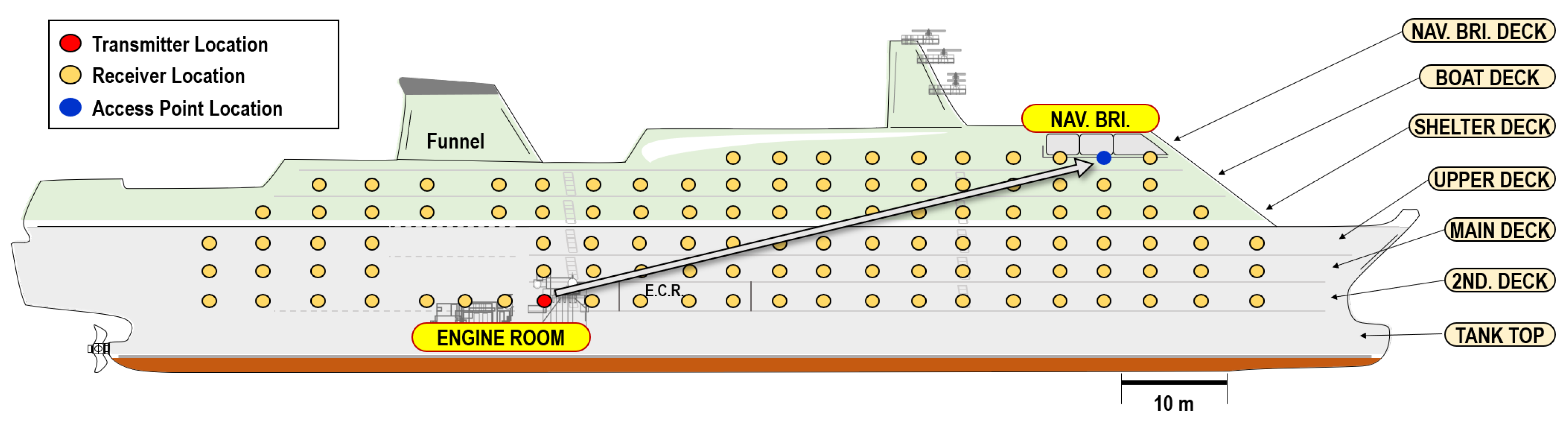
Figure 1b shows a brief view of the ship’s structure from the right.
The ship’s structure comprises multiple decks, each serving distinct functions and accommodating various facilities and equipment essential for the ship’s operation and training activities. The decks include the navigation and bridge, the boat, the shelter, the upper, the main, and the second deck. These decks collectively form an ideal setting for conducting wireless communication experiments and evaluating the performance of the multi-hop wireless network under challenging maritime conditions.
The second deck of the ship plays a crucial role in our research as it houses the engine control room and the main engine. This area serves as the focal point for our sensor installation, enabling real-time monitoring from the navigation and bridge deck. By strategically deploying sensors within the engine control room and near the main engine, we can gather valuable operational and safety information.
This paper specifically focuses on establishing effective communication from the engine room to the navigation and bridge deck. To achieve this objective, two experiments were conducted, as described in the
Section 4 and
Section 5. The experiments aimed to optimize the placement of routers within the ship and evaluate the performance of a multi-hop wireless network using the IEEE 802.15.4e Deterministic and Synchronous Multichannel Extension (DSME) MAC protocol.
3.3. Devices for Signal Strength Measurement
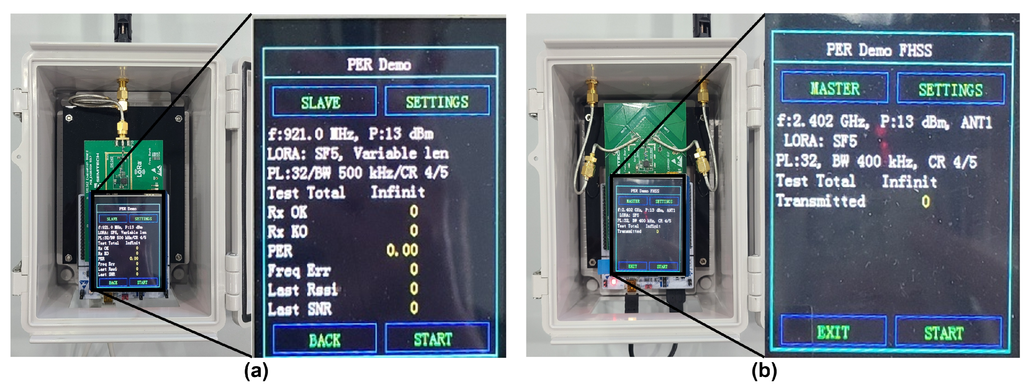
In this study, we employed two types of devices for conducting our experiments: the SX1262DVK1CAS for sub-1 GHz transmission and reception tests and the SX1280RF1ZHP for 2.4 GHz transmission and reception tests, as shown in
Figure 2. These devices were selected to evaluate the performance of different frequency bands within the ship environment. We conducted RSSI measurements using two transmitter–receiver pairs for each of the sub-1 GHz and 2.4 GHz bands.
In the experiment, we positioned devices operating in two different frequency bands in a same location and observed the signal strength of the received signals. The purpose of comparing these two devices was to determine the frequency bands and transmission distances that are suitable for stable communication within the vessel under identical conditions. This analysis allowed us to identify the optimal settings for reliable wireless communication within the maritime environment.
Table 1 shows the wireless parameters used in the RSSI measurement experiment for both sub-1 GHz and 2.4 GHz devices.
3.4. DSME Based Multi-Hop Network Construction
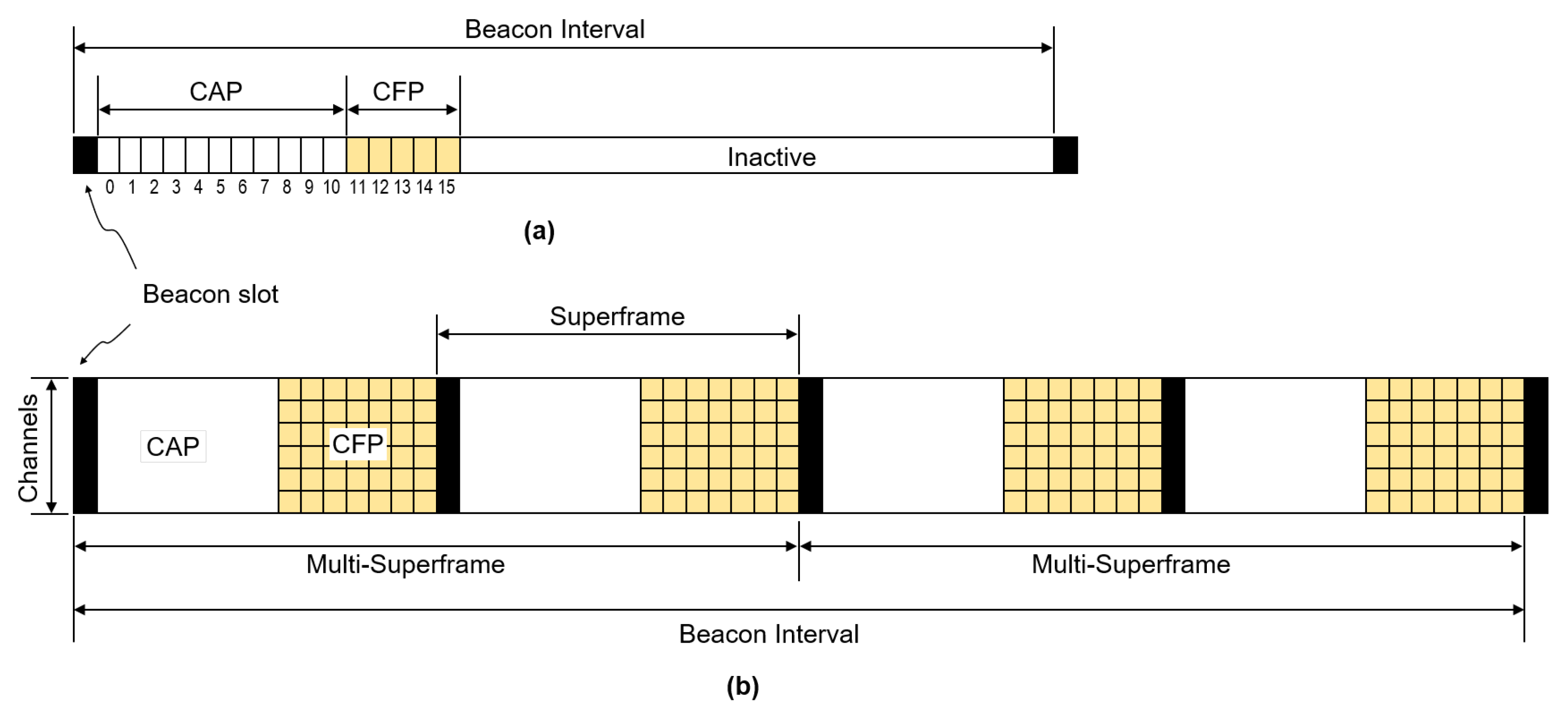
The multi-hop network implemented in this study is based on the IEEE 802.15.4e DSME MAC protocol, which extends the superframe structure defined in IEEE 802.15.4 by introducing multi-superframes.
Figure 3 shows the superframe structure for the IEEE 802.15.4 and IEEE 802.15.4e standards. The original superframe structure in the IEEE 802.15.4 standard includes components such as a beacon slot, a Contention Access Period (CAP), a Contention-Free Period (CFP), and an inactive period. In contrast, the IEEE 802.15.4e standard introduces enhancements, specifically the Deterministic and Synchronous Multichannel Extension (DSME). DSME retains the beacon slot for synchronization but enhances CAP and CFP by incorporating a deterministic and synchronized schedule for channel access.
The beacon slot is reserved for beacon frame transmission, which provides network configuration and synchronization information to other nodes. The CAP is used to schedule time slots and channels for data transmission. It is also used to exchange control messages. During the CAP, nodes contend for channel access using the CSMA/CA mechanism. In the CFP, each node is allocated a guaranteed time slot (GTS) for transmitting its data within an assigned time slot and channel, ensuring timely delivery of time-sensitive sensor data.
In addition, we choose the LoRa (long range) [
36] transmission as the physical layer (PHY). Unlike the original PHY of IEEE 802.15.4, which uses Direct Sequence Spread Spectrum (DSSS) in the 2.4 GHz or sub-1 GHz bands (Zigbee is a well-known example), LoRa introduces a proprietary modulation system developed by SemTech Semiconductor. LoRa uses Chirp Spread Spectrum (CSS) signals to effectively mitigate interference. The implementation of CSS ensures robust communications, especially in high-noise environments such as the confined spaces of a ship. In addition, LoRa’s power efficiency is noteworthy because it eliminates the need for complex signal processing. The adaptability of LoRa’s transmission characteristics, controlled by parameters such as spreading factor (SF), coding rate (CR), and bandwidth (BW), allows the radio to adjust transmission distance, speed and reliability, offering a compelling alternative to traditional DSSS-based approaches.
Figure 4 shows the linear multi-hop network topology considered in this paper. The multi-hop network architecture implemented in this study consists of a network management server (NMS), an access point (AP), routers, and end devices. The NMS starts and manages the network, discovers active networks, selects the best channel, and configures network parameters. The AP acts as a central hub, facilitating communication between the NMS, routers, and end devices. A router acts as an intermediary, receiving and relaying sensor data transmitted by the end devices. The end devices collect sensor data and transmit them to the NMS through one or more router(s) and the AP.
By leveraging the deterministic and synchronous nature of the DSME MAC protocol and the reliable communication capabilities of LoRa PHY, our multi-hop network implementation aims to ensure robust and extended wireless coverage in IoT deployments. The combination of these technologies enhances reliability, latency control, scalability, and power efficiency, enabling efficient data transmission and communication in challenging IoT environments.
The parameter values listed in
Table 1 for the sub-1 GHz band are also utilized in the implementation of the multi-hop network. These values serve as the basis for configuring the network and ensuring consistent performance across the communication links.
3.5. Considerations for Device Installation
During the planning phase of our experiment, we established a rule to place the devices exclusively within the interior of the ship, considering specific concerns raised by the ship’s personnel. This decision was based on the recognition of potential issues associated with positioning the devices on the ship’s exterior. The primary concern highlighted was the vulnerability of the devices to harsh environmental conditions, such as salt water, extreme temperatures, humidity, and physical impacts from waves or debris. Placing the devices outside could significantly compromise their performance and durability. Furthermore, we acknowledged the challenges related to stability and mounting. To ensure the devices could withstand the ship’s movements, vibrations, and strong winds, it was crucial to securely mount them within the ship’s interior. Additionally, accessibility for maintenance and troubleshooting was taken into consideration. Placing the devices on the ship’s exterior would complicate necessary servicing, battery replacement, or addressing technical issues promptly.
4. Experiment 1: Signal Strength Measurement
4.1. Measurement Preparation and Steps
In the first experiment, our goal was to determine the coverage of the radio signal throughout the ship. After selecting the initial transmitter location, we initiated the RSSI measurements by sequentially changing the receiver location, starting with nearby points and moving outward. After completing the measurements at one tranmitter location, the measurements moved to the next receiver location. The measurement steps are shown in
Figure 5. The ship’s floor plan is represented on a Cartesian coordinate system. The X-axis represents the longitudinal direction of the ship, from the stern (X = 0) to the bow (X = 120 m). Meanwhile, the Y-axis represents the transverse direction, with the right side of the ship labeled Y = −10 m and the left side labeled Y = 10 m. In the future, only numerical values without units will be used to represent X or Y coordinates in this paper.
Figure 6 shows the receiver locations on each level, along with the transmitter location in the engine room and the access point (AP) location on the navigation bridge. While varying the transmitter locations, an effort was made to position the receivers at or near the marked points in the diagram.
At each marked location, we took measurements of the average received signal strength indicator (RSSI) for both sub-1 GHz and 2.4 GHz transmissions using two transmitter–receiver pairs. Each measurement took approximately 10 to 20 s, during which time the instantaneous RSSI values were recorded and averaged. These measurements provided a valuable insight into the overall radio wave transmission pattern from the transmitter to the floor.
Once the measurement at a particular location was completed, the next transmitter location was selected based on the previous measurement to ensure successful reception with an RSSI value that met predefined criteria. This iterative process continued until the navigation bridge was reached. Empirical testing led us to adopt an RSSI threshold of −75 dBm or higher in the sub-1 GHz band as an indication of a viable router node location. Specifically, an RSSI value of −75 dBm was considered to ensure reliable communication using LoRa transmission. However, it is important to note that the optimal RSSI value for reliable communication over LoRa may vary due to factors such as distance, interference, signal strength, etc.
To compare the variations in signal strength between different radio bands, we placed both sub-1 GHz and 2.4 GHz devices at each location for both the transmitter and receiver. This allowed us to analyse and evaluate the signal strength characteristics of the two radio bands in the given environment. By systematically measuring and comparing the signal strengths at different locations and radio bands, we aimed to identify the optimal transmitter locations with the best signal strengths.
4.2. Results and Analysis
The measured RSSI values are depicted in the floor plan shown in
Figure 7,
Figure 8 and
Figure 9. The measured values in these figures are represented in
aa/bb format, where
aa represents the measured RSSI value for the sub-1 GHz band and
bb represents the value for the 2.4 GHz receiver. Both values are shown without the minus sign. For instance, the value 40/55 indicates −40 dBm and −55 dBm, respectively. In cases where no signal was received at all, we marked the value as 99, signifying that the RSSI is less than −99 dBm.
4.2.1. Transmission from the Engine Room
In our signal strength measurement, we began from the second deck, which houses the engine room and the engine control room. As shown in
Figure 10a, the transmitter is positioned at coordinates X = 56, Y = 5 within the second deck, specifically inside the engine room (Tx
).
As shown in
Figure 10a, the RSSI values around the engine room are good enough above −70 dBm across the engine room for both sub-1 GHz and 2.4 GHz bands. It shows that the sub-1 GHz is 5 to 10 dBm stronger than the 2.4 GHz. The result is similar for the engine control room, which is located right next to the engine room around X = 65 to 70. However, the RSSI value drops significantly outside the engine control room because the signal has to penetrate two heavy iron doors. Consequently, the measured values for sub-1 GHz are around −80 dBm, but the 2.4 GHz is below −99 dBm.
The measurement results in
Figure 10b–e provide an overview of the RSSI measurements obtained from different decks of the ship. Each figure corresponds to a specific deck, namely the main deck, the upper deck, the shelter deck, and the boat deck. Throughout these figures, the transmitter is located in the engine room.
On the main deck (in
Figure 10b), sub-1 GHz is still around −70 dBm, but 2.4 GHz almost fails to reach this area and is recorded as −99 dBm. The received signal strength decreases on the upper deck, shelter deck, and boat deck.
During our test, we discovered the presence of machinery spaces on board. These are located directly above the engine room and extend over several levels. At their highest point, they extend down to the shelter deck, which lies just below the ship’s funnel. The machinery spaces are dedicated areas where many mechanical systems, machinery, and piping are located.
The influence of the machinery spaces on the measurement results was obvious and can be observed in the data presented, partly in
Figure 10c and especially in
Figure 10d. In
Figure 10c, which shows measurements taken outside the machinery spaces on the upper deck, only weak signals were detected close to the spaces. However,
Figure 10d provides a valuable insight as it shows measurements taken inside the machinery space on the shelter deck. Significantly stronger signals were recorded at this location, reaching around −50 dBm for both sub-1 GHz and 2.4 GHz frequencies.
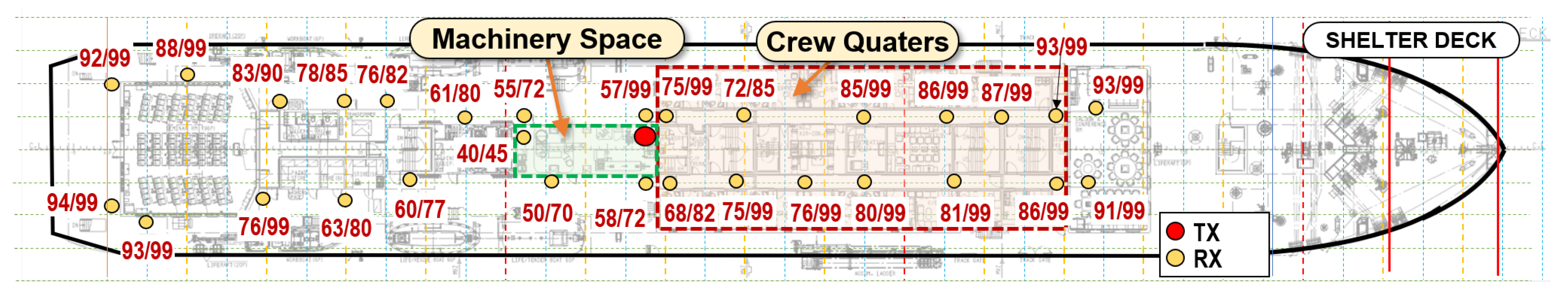
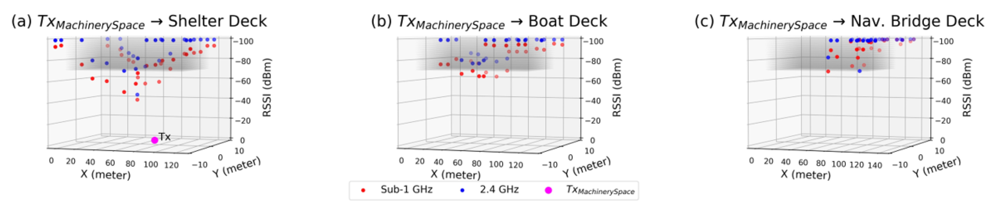
4.2.2. Transmission from the Machinery Space on the Shelter Deck
The measured RSSI values on the shelter deck when the transmitter is placed inside the machinery space with coordinate X = 68 and Y = 3 are depicted in the floor plan shown in
Figure 8. When the transmitter is placed inside the machinery space, there are still several places where the RSSI values are reasonably high on the exterior part of the shelter deck. However, inside the crew quarters through the hallway, the values are becoming lower, almost below −80 dBm. Only an exceptional place can be found that is close to the machinery space, where we obtained an average of −72 dBm, making it a good candidate place for another transmitter position. The overall measured values are plotted in 3D graphs in
Figure 11, showing measured values on the shelter, boat, and navigation bridge decks. On the boat and navigation bridge decks, only weak signals of the sub-1 GHz band are received on the exterior part of the ship.
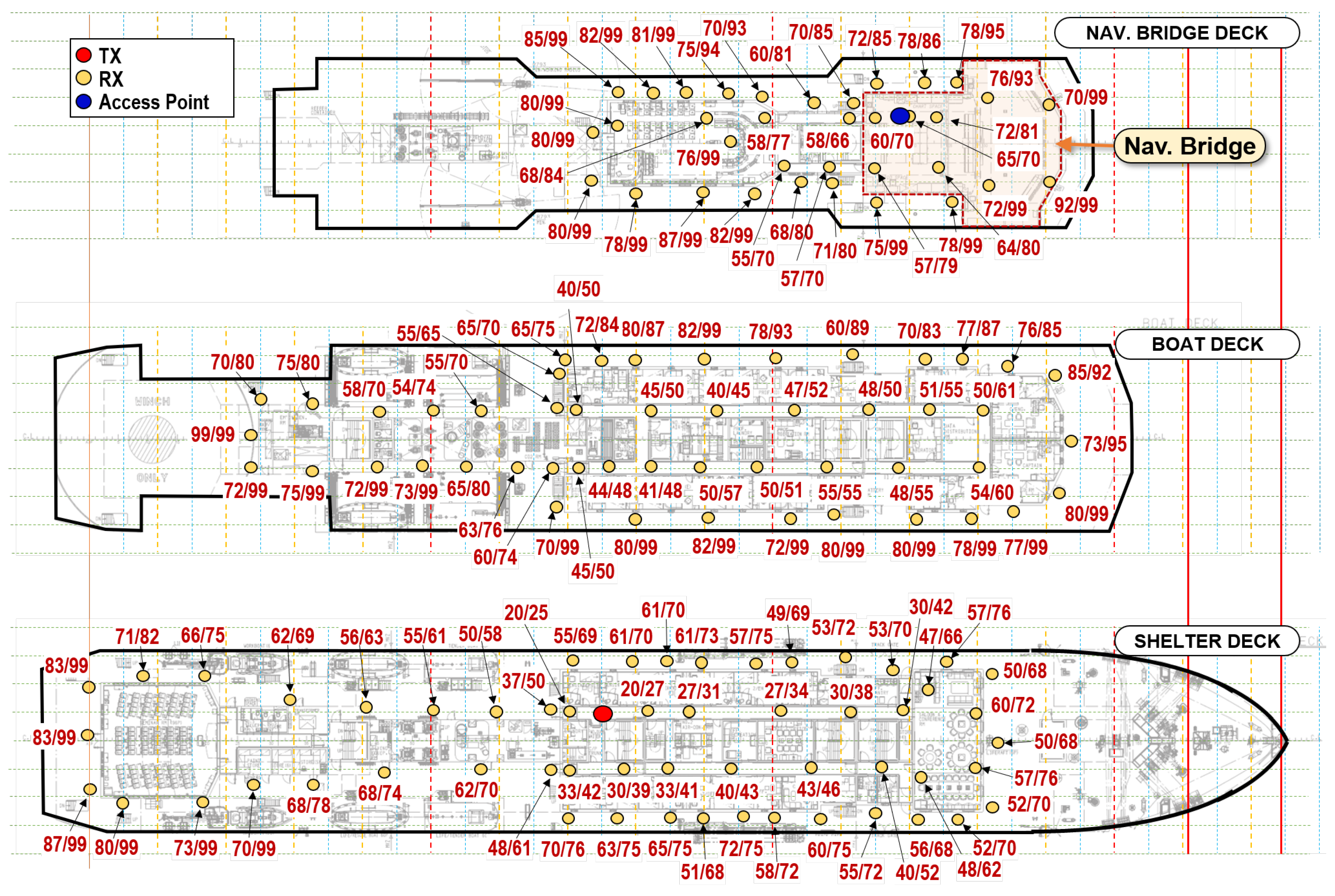
4.2.3. Transmission from the Hallway of the Shelter Deck
Figure 9 shows the measured RSSI values throughout multiple levels, shelter, boat, and nav. bridge decks when the transmitter is located inside the crew quarters hallway close to the machinery space. In the previous subsection, we noted that X = 75, Y = 5 is the best place to put the transmitter. The measurement result clearly shows that the location can cover most of the places interior of the three decks for the sub-1 GHz band. It is noticeable that the interior signal propagation of the 2.4 GHz band also shows strong signal strength on the shelter deck and moderate signal strength on the boat deck. But it becomes weaker at two levels above it, so one-hop transmission could not reach the access point located inside the navigation bridge.
This characteristic can also be found in
Figure 12. In
Figure 12a, the RSSI values around the shelter deck are good enough above −75 dBm across the interior part for both the sub-1 GHz and 2.4 GHz bands. On the boat deck, as shown in
Figure 12b, there are still many places where the signal strength is reasonable.
4.3. Summary
In summary, the following findings were discovered in this measurement study:
RSSI values around the engine room (and the engine control room) are good enough above −70 dBm over the engine room for both the sub-1 GHz and 2.4 GHz bands. Thus, it appears that the heavy metal components, intricate piping networks, and a variety of machinery and equipment in the engine room do not attenuate too much. Therefore, only one router is needed to cover the entire engine room.
Radio signals could not penetrate two adjacent heavy iron doors, as seen from the measurement outside of the engine control room. A router node will be needed in such a configuration.
The LoRa transmission in a large ship using the sub-1 GHz band can successfully reach more than two levels, while the 2.4 GHz can reach only one level when both the transmitter and receiver are placed in the interior part or the hallway of the ship.
On the other hand, any receiver in the exterior part will have to penetrate at least one heavy iron door, which will have a negative effect of more than 20 dBm on the signal strength.
It is worth noting that the presence of machinery spaces, located above the engine room, has a significant impact on signal strength. Our measurements taken inside these spaces at the shelter deck revealed considerably stronger signals, reaching approximately −50 dBm for both the sub-1 GHz and 2.4 GHz frequencies. This finding suggests that the machinery spaces can be utilized in establishing multi-hop networks in large ships, taking advantage of their signal propagation characteristics.
Given the results of this measurement study, we now turn our attention to building a robust multi-hop network throughout the ship. The next section builds on the observations made in this section to strategically select router locations and optimize packet forwarding efficiency. The knowledge gained from the measurement study, including signal strengths at various ship locations and the impact of structural elements, informs our approach to creating a network that ensures reliable communications.
5. Experiment 2: Network Construction and Data Acquisition
5.1. Network Setup
In the second experiment, our goal was to select suitable locations for the routers and establish a complete multi-hop network throughout the ship. We selected the router locations based on the results of the previous measurement experiment. We considered elements such as signal strength and communication range. For example, based on observations of signal attenuation both inside and outside the engine control room, selecting a horizontal path through the second deck corridor will require more routers than selecting a vertical path through the engine room to the shelter deck. In addition, we decided to use sub-1 GHz frequencies rather than 2.4 GHz within the ship’s confines (narrow corridors and stairwells) to allow signals to travel longer distances.
A number of factors were taken into account when selecting router locations for efficient packet forwarding. The primary objective was to minimize the total number of routers, which led to the decision to place each router as far apart as possible while maintaining an average received signal strength indicator (RSSI) value greater than −75 dBm. By strategically placing the routers in locations with favorable RSSI values, the aim was to ensure reliable signal reception and transmission throughout the ship.
Ease of installation was also a key factor. Selecting locations that were easily accessible and suitable for router placement was essential to facilitate the installation process. It was crucial to select areas within the ship that would not be susceptible to damage or interference caused by the movement of crew members or passengers. This consideration was essential to maintain the integrity and stability of the routers and antennas to ensure uninterrupted communications within the ship’s environment. As mentioned earlier, we also planned to place the routers only inside the ship to compensate for any management issues that might arise from placing routers on the outside.
With these factors in mind, the selection of router locations was aimed at optimizing the efficiency of packet forwarding while minimizing the number of routers and taking into account the practicalities of installation and potential risks of damage.
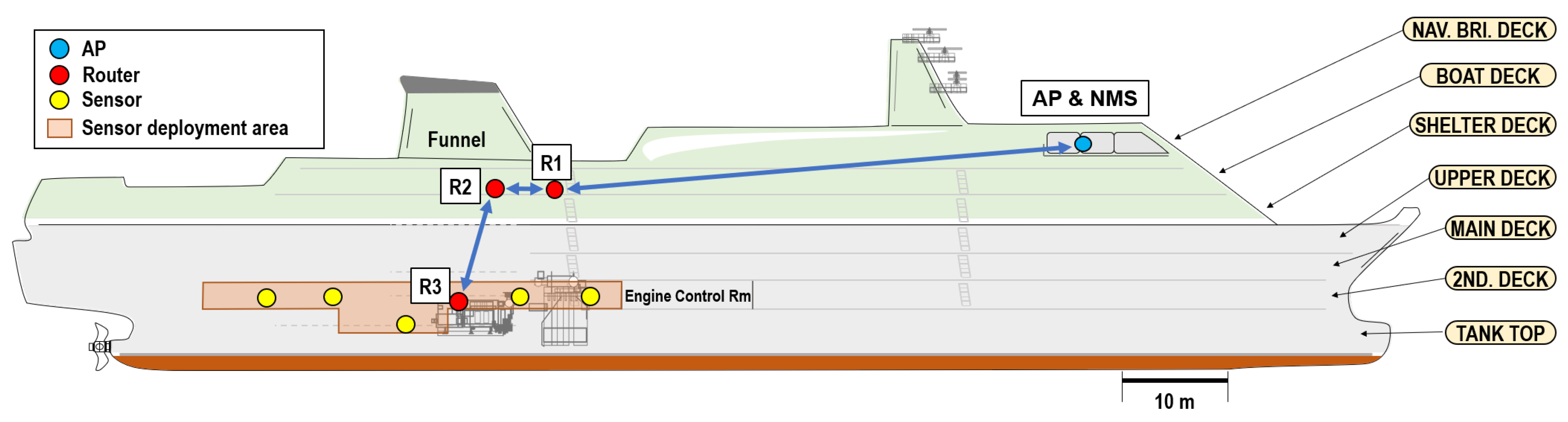
Figure 13 shows the installation layout for the data acquisition experiments in the ship’s test environment. The network management server (NMS) was installed on the laptop to set up a DSME network. It allocates channels and time slots for the entire network based on available guaranteed time slots (GTSs) and sets up routing paths. Router
was installed on the shelter deck corridor in close proximity to
, which was installed in the engine room.
was installed in the engine room. We also placed several sensors around the engine room to verify that the data was successfully collected from the navigation bridge.
To carry out this evaluation, we strategically placed several sensors in the engine room, each of which was specifically designed to generate fixed-size data packets at regular intervals, including the packet header. By measuring the inter-packet arrival time of the packets received from each sensor, we were able to assess the stability of the network by looking for any noticeable changes or pauses in packet delivery.
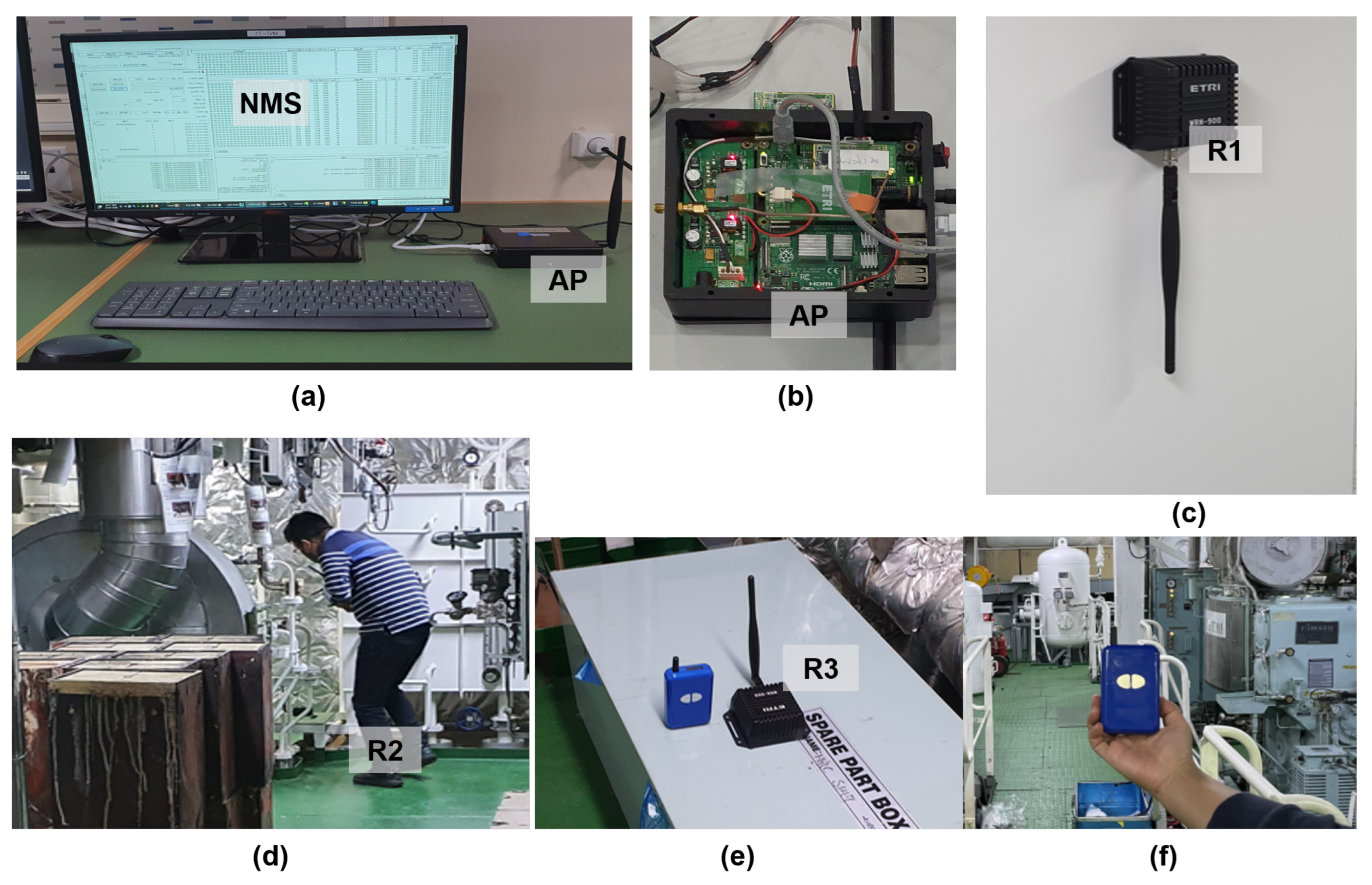
Figure 14 shows photos of the device placements for the experiment.
5.2. Inter-Packet Arrival Time
To further investigate the time sensitivity aspect, we introduced specific configurations for selected sensors. Several sensors were programmed to transmit data during the Contention Access Period (CAP) using the CSMA/CA (carrier sense multiple access with collision avoidance) mechanism. This allowed data transmission to be contention-based, with nodes accessing the medium based on channel availability and collision avoidance algorithms. In contrast, other sensors were configured to transmit data during the Contention-Free Period (CFP) using the guaranteed time slot (GTS) mechanism. GTS provided dedicated time slots for specific sensors, ensuring that their transmission time was guaranteed and protected from contention.
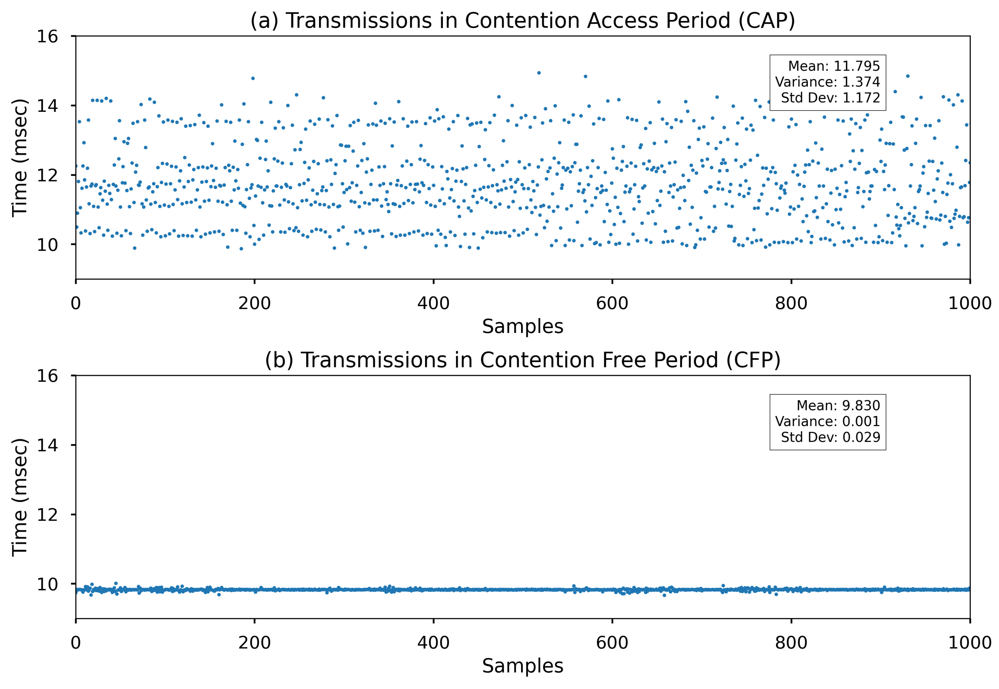
Figure 15a,b show the transmission results of the Contention Access Period (CAP) and the Contention-Free Period (CFP), respectively, in terms of inter-packet arrival time. The data arrival time was recorded by the network management server (NMS) for analysis.
Figure 15a shows the inter-packet arrival time for a sensor node during CAP transmission. As CAP transmission uses contention-based resources, it is subject to random delays in a best-effort scenario, with an average inter-packet arrival time of 11.795 ± 1.172 (ms). This variability in inter-packet arrival time reflects the nature of contention-based transmission, where nodes compete for channel access.
On the other hand,
Figure 15b shows the transmission results for CFP. In the case of CFP, guaranteed time slots (GTSs) are pre-allocated by the NMS to ensure that transmission opportunities are guaranteed for specific sensor nodes. The figure illustrates the inter-packet arrival time during CFP transmission, where the average inter-packet arrival time is measured to be 9.830 ± 0.029 (ms). This result means that the transmission opportunity for nodes assigned to GTSs is reliably guaranteed, providing a more predictable and consistent transmission experience.
The analysis of these transmission results in
Figure 15a,b allows us to gain insight into the performance characteristics of CAP and CFP in terms of inter-packet arrival time in a multi-hop configuration. The random delay observed in CAP transmission highlights its contention-based nature, while the pre-allocated GTS in CFP ensures a more predictable transmission experience with reduced variability in inter-packet arrival time. These findings contribute to our understanding of the effectiveness of different transmission mechanisms and their implications for time-sensitive applications within the multi-hop wireless network.
5.3. Reliability
The network configuration utilized in the test uses the sub-1 GHz band parameters in
Table 1. In the scenario, sensor data were transmitted at approximately 9.8 s intervals. Therefore, the results in
Figure 15, collected from 1000 samples, correspond to approximately 2.74 h for both CAP and GTS transmissions. To increase the probability of successful packet reception, router locations were chosen to maintain positions with signal strengths above −75 dBm. For both CAP and GTS transmissions, each transmit–receive pair exchanged an Ack (acknowledgement) packet for each packet to determine success. If an Ack was not received within a specified time, the transmitter would repeat the packet transmission up to three times.
In this study, there was no packet loss during the entire measurement time, as shown in
Figure 15a,b. Considering the distance from the engine room to the navigation bridge and the number of routers used, this result is remarkable when compared to the results of other studies. For example, in the study by Kdouh et al. [
15], using Zigbee communication in the 2.4 GHz band, packet losses were measured in the range of about 2% to 7% (results vary slightly depending on the installation position). Another study using Zigbee [
9] showed similar results, indicating that it is not possible to achieve 100% successful reception over a relatively short tx-rx distance of about 40 m. However, it is important to note that it is difficult to directly compare results due to differences in the frequency band, depth of multiple hops, length of transmit and receive, communication protocols, and physical layers used between the studies.
6. Conclusions
This study addressed the challenges of wireless sensor communication in marine environments through a multi-hop wireless network using the IEEE 802.15.4 DSME MAC protocol. Valuable insights were gained regarding signal propagation, router placement, and utilization of the DSME MAC protocol.
The feasibility of a multi-hop network was evaluated by comparing sub-1 GHz and 2.4 GHz transmissions, highlighting their advantages and limitations in ship communications. In particular, the sub-1 GHz band shows considerable success in reaching more than two levels within the ship. The 2.4 GHz band, on the other hand, has a more limited range, reaching only one level. This difference underscores the importance of frequency band selection and highlights the superior coverage and penetration capabilities of the sub-1 GHz band, especially in challenging maritime environments characterized by steel structures and signal attenuation.
A multi-hop network was constructed and demonstrated using the DSME MAC protocol. Experimental results confirmed the stability and time-sensitivity of the multi-hop network, showcasing the capabilities of the IEEE 802.15.4 DSME MAC protocol for reliable data transmission in ship environments. The ability of the protocol to allocate time slots and mitigate interference was beneficial for time-sensitive applications on board ships.
Our study advances wireless sensor communication on ships and provides an evaluation for establishing multi-hop networks using the IEEE 802.15.4 DSME MAC protocol. The proposed solutions and findings will enhance communication capabilities, improve efficiency, and support ship applications with reliable data transmission.


