Review

A Comprehensive Review on Material Compatibility and Safety Standards for Liquid Hydrogen Cargo and Fuel Containment Systems in Marine Applications

1
Department of Reliability Assessment, Korea Institute of Machinery and Materials, Daejeon 34103, Republic of Korea
2
Department of Marine Systems Engineering, Korea Maritime & Ocean University, Busan 49112, Republic of Korea
*
Author to whom correspondence should be addressed.
J. Mar. Sci. Eng. 2023, 11(10), 1927; https://doi.org/10.3390/jmse11101927
Submission received: 4 September 2023 / Revised: 28 September 2023 / Accepted: 4 October 2023 / Published: 6 October 2023
(This article belongs to the Special Issue Novel Maritime Techniques and Technologies, and Their Safety)

Abstract

:
As the maritime industry’s emphasis on sustainable fuels has increased, liquid hydrogen (LH2) has emerged as a promising alternative due to its high energy density and zero-emission characteristics. While the experience of using natural gas in ships can serve as a basis for the introduction of hydrogen, the different risks associated with the two fuels must also be considered. This review article provides a methodology for selecting suitable metal materials for shipboard LH2 storage and piping systems based on operational requirements. The effects of both liquid and gaseous hydrogen environments on metal materials are first comprehensively reviewed. The minimum requirements for metal materials in liquefied natural gas (LNG) storage systems, as stipulated in the IGC and IGF codes, were used as a baseline to establish minimum requirements for liquid hydrogen. The applicability of austenitic stainless steel, a representative metal material for cryogenic use, to a liquid hydrogen environment according to nickel content was examined. In order to apply liquid hydrogen to the marine environment, the minimum requirements for liquid hydrogen were organized based on the minimum requirements for metal materials in the LNG storage system covered by the IGC and IGF codes. Finally, to expand the material selection criteria for low-temperature cargo and fuel storage facilities at sea, slow strain tensile testing, fatigue life, and fracture toughness considering the hydrogen environment and cryogenic temperature were derived as evaluation items.

1. Introduction

Regulations on greenhouse gas emissions from ships have continuously been strengthened in an effort to address global warming and greenhouse gas issues faced by the shipping industry. In accordance with the greenhouse gas reduction initiative proposed by the International Maritime Organization, various eco-friendly fuels are being proposed for use as ship propellants [1,2], and there have been efforts to utilize both fuel cells and liquid hydrogen, which has a high energy density, as sources of propulsion for large maritime vessels [3,4,5,6]. In countries such as Korea and Japan, the introduction of liquid hydrogen carriers is currently under consideration to import large amounts of hydrogen from overseas sources for the achievement of carbon neutrality. Therefore, increasing attention has been paid to cargo containment systems for liquid hydrogen. It was not until the introduction of Suiso Frontier, a liquid hydrogen carrier produced by Kawasaki Heavy Industries, Japan, and MF Hydra, a liquid hydrogen-fueled ship produced by Norled, Norway, that ships equipped with liquid hydrogen storage containers started to operate in practice [7]. This was because it was difficult to fabricate a dual-vacuum container with excellent insulation performance, allowing large amounts of hydrogen to be transported and utilized for a long period of time. In addition, back then, there was less demand for the maritime transport of liquid hydrogen. Up until recently, hydrogen was stored and transported while being in a gaseous state, and most facilities were designed as a ground fixing or portable type. Various attempts have been consistently made to find ways to store liquid hydrogen since the 1960s, but the demand was so low that rather less attention was paid to this sector compared to research fields related to gaseous hydrogen.
The Sub-committee on Carriage of Cargoes and Containers (CCC) of the IMO started to establish safety standards for hydrogen fuels to achieve its greenhouse gas reduction goal. Not only the Interim Recommendations for Carriage of Liquefied Hydrogen in Bulk published by the Maritime Safety Committee (MSC) in 2016 but also the Interim Guidelines for the Safety of Ships Using Hydrogen as Fuel proposed by Norway in 2022 were basically drafted with reference to ISO/TR 15916 “Basic Considerations for the Safety of Hydrogen Systems”. ISO/TR 15916 defines basic safety considerations and risks and provides specific descriptions of them so that they can be applied to a wide range of industrial fields. With that said, it does not cover specific safety requirements for the application of hydrogen, and thus, one needs to refer to other standards to access such information. Details of applicable materials for different storage states of hydrogen can be found in ANSI/AIAA G–095A–2017 “Guide To Safety Of Hydrogen And Hydrogen Systems”.
In selecting materials for hydrogen storage and transport, compatibility assessment, considering the environmental characteristics of the system, is considered the top priority [8]. By contrast, in LNG storage systems, the choice of material primarily depends on the design temperature of −163 °C, since natural gas does not typically react with metallic materials. Hydrogen, depending on its intended application, can be stored or transported either in gaseous or liquid states. However, additional consideration must be given to hydrogen embrittlement, which is a phenomenon where hydrogen infiltrates the metal, deteriorating its ductility and toughness [9,10,11]. This effect relies on three key factors: the hydrogen atmosphere, the properties of the material, and the stress or load conditions. As the outcomes of hydrogen embrittlement can vary based on the system’s specific part where it occurs, the range of materials that are compatible with these particular conditions can also vary. Therefore, it is crucial to conduct a comprehensive examination of each material’s applicability. For instance, the 8th Technical Conference for the Phase 2 revision of the Global Technical Regulation on Hydrogen and Fuel Cell Vehicles (October 2020) discussed that the list of materials suggested for each hydrogen environment system, outlined in the Safety Standards (NSS1740.16) by the National Aeronautics and Space Administration (NASA), cannot serve as a basis for material selection, since this list only screens data based on temperature and hydrogen embrittlement and does not consider fatigue assessments. Since the longer the load cycle, the faster the crack propagation rate due to the intrinsic characteristics of hydrogen, thereby leading to reduced fatigue life, the load condition should be considered an important evaluation parameter. For the hydrogen storage and piping system of ships as well, the characteristics of the hydrogen atmosphere are considered to hold great significance in the compatibility assessment of materials.
Despite the importance of material compatibility for hydrogen service, most prior studies on hydrogen fuel have primarily focused on improving the economics and efficiency of hydrogen fuel in marine applications. As such, they have often limited their discussions to listing acceptable materials as specified in ANSI/AIAA G–095A–2017 [1,5,6,12]. In addition to the costs associated with hydrogen fuel production and fuel cells, it is critical to assess the material costs, which constitute a significant part of the storage and transportation system’s overall expenses, to ensure commercial viability. Similar approaches have been observed in LNG storage systems where efforts have been made to use materials with lower nickel content or to replace them with high-manganese steel [13,14,15,16,17,18,19,20]. While using 316L stainless steel, known for its excellent hydrogen resistance, may be a safe choice for material selection, applying it universally across all hydrogen environments can be inefficient. Cold-rolled 316 stainless steel costs about 1.5 times as much as 304 stainless steel; considering the large amount needed for storing liquid hydrogen in vessels, the cost difference depending on material selection can be substantial. Accordingly, economic evaluations based on the choice of materials for gaseous hydrogen pipelines are already being conducted on land [21].
On that note, this review article aims to propose a procedure for selecting suitable metallic materials based on the operational requirements for liquid hydrogen storage containers and piping systems for ships. The minimum requirements for LNG and liquid hydrogen storage systems were reviewed and compared for applicable materials for each system. The requirements for material selection in international safety regulations and the effects of hydrogen on the mechanical performance of metal materials were also summarized. A slow strain-rate tensile test, fatigue life, and fracture toughness considering the hydrogen environment were derived as evaluation items to expand the material selection criteria for containment facilities for storing low-temperature cargo and fuel on ships from conventional low flash point fuels to hydrogen. This review article serves as an extended version of the “Research Report of Material Compatibility for Liquid Hydrogen Storage on Marine Application” [22] and additionally discusses the mechanical performance of austenitic stainless steel in hydrogen environments based on nickel content. The article also covers an additional discussion on MSC.1/Circular.1622 in the context of liquid hydrogen applications.

2. Issues with Metallic Materials Applied to Liquid Hydrogen Storage

The inherent risks of hydrogen arise mainly from its one-of-a-kind physical properties and its interactions with various materials. Hydrogen, whether in gas, liquid, or hydrate form, presents unique challenges that require careful consideration during storage and handling. This section investigates how the hydrogen atmosphere influences the mechanical characteristics of metallic materials. Critical factors that influence the test conditions, such as temperature, hydrogen exposure conditions, hydrogen partial pressure, and strain rate, are explained.

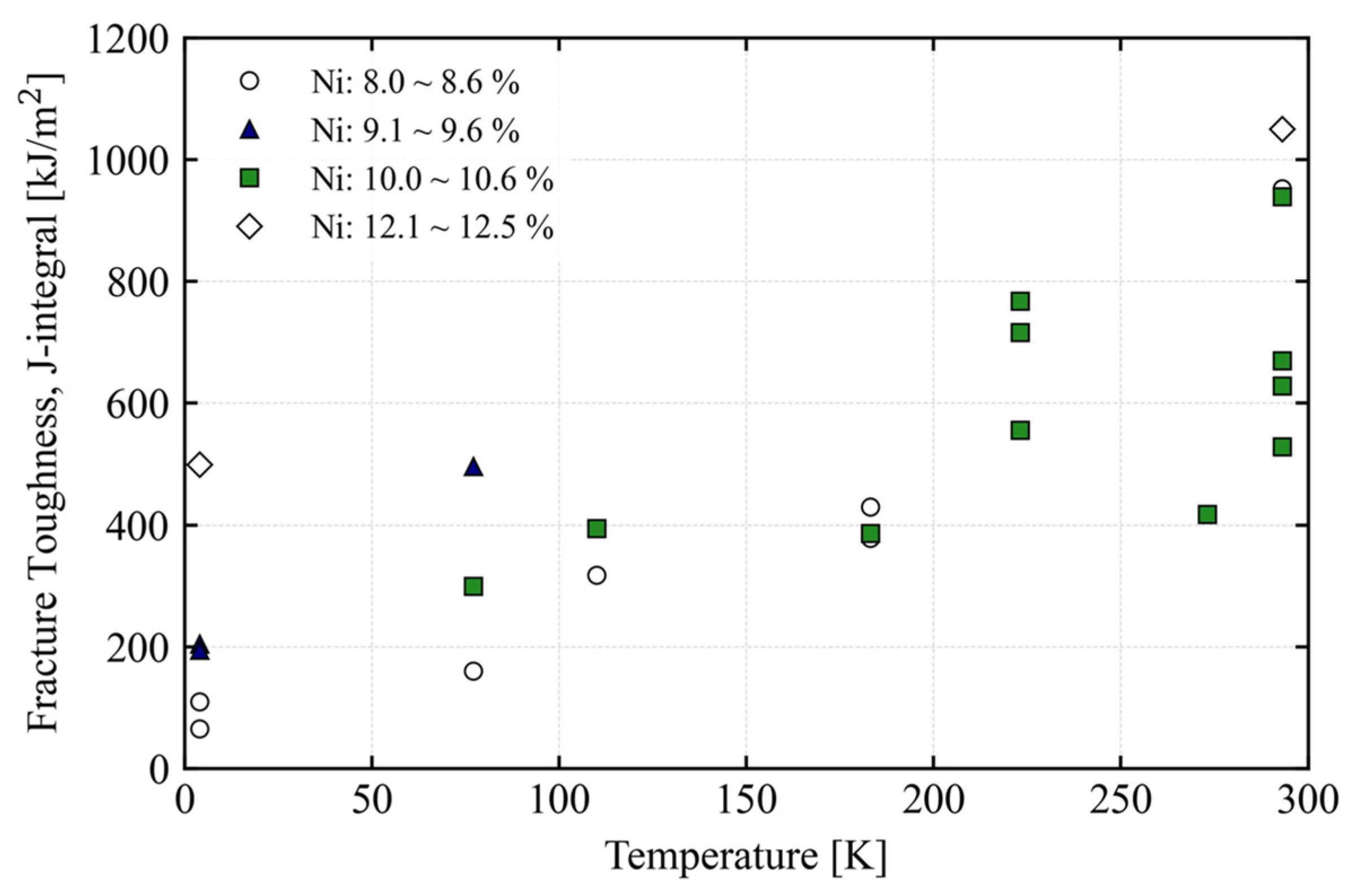
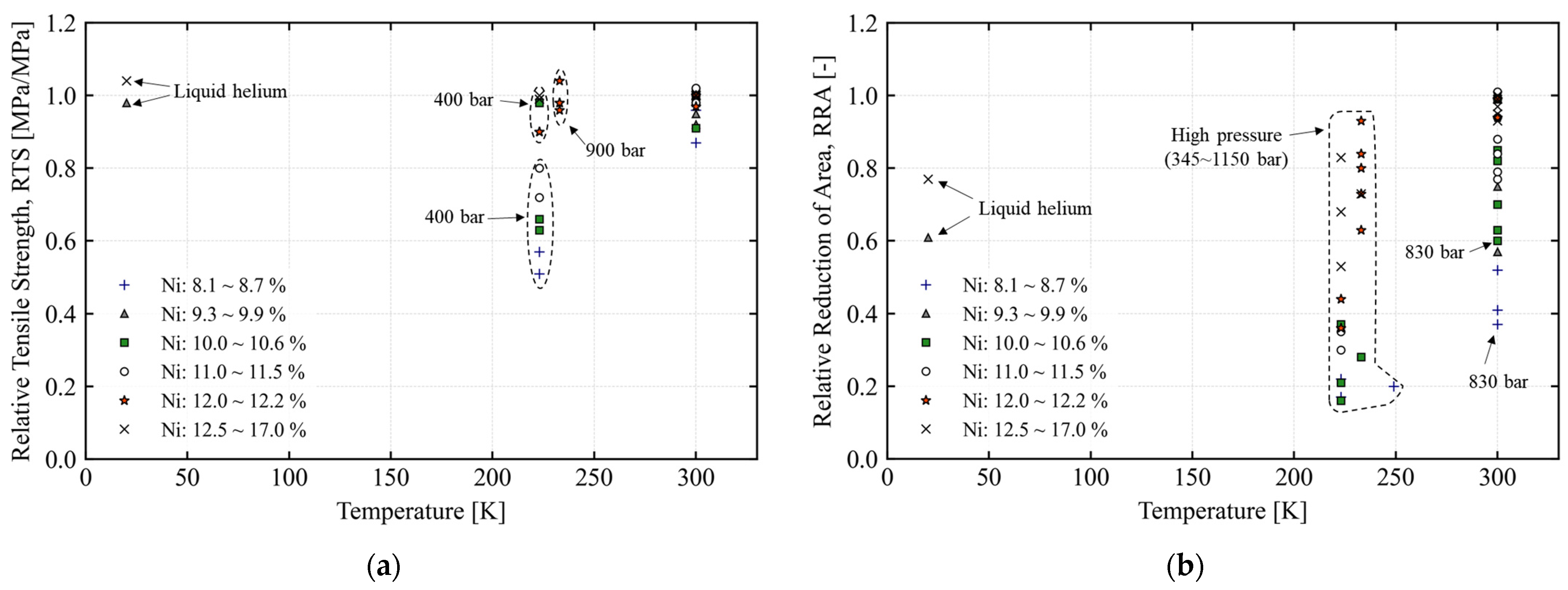
2.1. Effect of Low Temperature

Materials usually experience changes in their inherent characteristics due to temperature change. Such changes can yield favorable outcomes from a design perspective. However, in several cases, limitations are imposed on the temperature range in which materials can be used. Hence, it is crucial to evaluate the suitability of materials at the design temperatures considering properties like yield strength, tensile strength, elongation, fracture toughness, fatigue characteristics, and coefficient of thermal expansion. For example, for austenitic stainless steels, the yield and tensile strength increase and the elongation decreases as the temperature decreases. Low-temperature embrittlement becomes one of the significant challenges faced at low temperatures. The identification and assessment of this phenomenon involve pinpointing the temperature at which a material’s ductility changes to brittleness. Figure 1 shows the fracture toughness of austenitic stainless steel as a function of temperature [23,24,25,26,27,28,29,30]. The selected 304, 304 L, and 316 L austenitic stainless steels have nickel contents ranging from 8.0 to 10.6%, and all were evaluated for fracture toughness by deriving the J-integral according to ASTM E1820. Although manufacturing and testing conditions varied, decreasing temperature and lower nickel content generally resulted in decreased fracture toughness.
Metallic materials expand and contract significantly with changes in temperature. Thermal stresses can arise if the materials are geometrically constrained and free expansion or contraction are prevented. These constraints can cause materials to exceed their yield stress even under minimal external forces. Since it is crucial to minimize stress levels to mitigate the effects of hydrogen embrittlement (including residual stress), it is essential to minimize thermal stresses caused by thermal contraction. In addition, components such as Oprings can experience reduced sealing efficiency due to excessive thermal contraction.
Blocking or significantly reducing heat transfer inside and outside the hydrogen storage container is crucial for maintaining it at ultraplow temperatures. In this regard, a dual-vacuum insulation structure emerges as the most effective strategy. Insufficient insulation in a liquid hydrogen storage and transfer system can lead to vaporization of the liquid hydrogen. The resulting vaporization can cause a sharp rise in internal pressure and may cause the system’s compartmentalized temperature to drop below the intended temperature. This issue not only poses an economic problem caused by the loss of stored hydrogen, but it also raises significant concerns about structural integrity, which calls for careful attention.
In contrast to room temperature, a somewhat different physical phenomenon can be observed in cryogenic environments below 20 K. When tensile testing in cryogenic environments, the force-time and force-elongation data before and after the yield strength may exhibit a serration phenomenon that causes discontinuous yield. Discontinuous yield can be defined as an instability in the stress-strain line, which can be observed in certain temperature and strain rate regions in tensile testing. This phenomenon is observed in stainless steels, aluminum alloys, and nickel alloys [31]. This phenomenon is caused by the successive locking and unlocking of dislocations that occur during deformation, resulting in a progressive enlargement of the deformed area [32,33,34].
In cryogenic environments, sudden temperature increases can occur, which can be caused by adiabatic heating due to the very low thermal conductivity at cryogenic temperatures. This causes the strain rate to be limited during tensile testing. Therefore, it is recommended that the strain rate in tensile testing should not exceed 10−3 s−1 [35], and for fatigue testing, a temperature rise of 1 K has been observed in a study conducted on a titanium alloy at 4 K with a frequency of 5 Hz [36]. Based on these findings, Ogata (2014) recommended a stress ratio of 0.01 and a frequency of 2 Hz to suppress the temperature rise when performing fatigue tests at 20 K [37].
The U.S. National Institute of Standards and Technology (NIST) performed a fracture toughness test at quasi-static strain rates instead of the Charpy impact test at 4 K on a 316 L stainless steel plate after welding, and they found a sevenfold reduction compared to the vaporization temperature of liquid nitrogen, 77 K [38]. The reason for not performing the Charpy impact test is that it is difficult to maintain the target temperature due to factors in the external environment and the material itself. In order to continuously maintain the target temperature when evaluating mechanical performance at cryogenic temperatures, it is important not only to ensure that the surrounding environment of the test specimen is kept at a constant temperature but also to minimize the temperature rise due to deformation of the test specimen. If the displacement control speed is too fast in a cryogenic environment, the temperature can rise rapidly, even for a test specimen that has reached 4 K or 20 K, and show a performance similar to 77 K [39]. In order to maintain 4 K near absolute zero, a cryostat with vacuum insulation is essential in the configuration of the test facility, and even thermal radiation from the external atmosphere must be controlled.
When performing the Charpy V–notch impact test, it is difficult to configure a cryostat to reach the target temperature. Most researchers use liquid nitrogen–immersed specimens that are then transferred to an impact tester. ASTM E23 (Standard Test Methods for Notched Bar Impact Testing of Metallic Materials) recommends performing the impact test within 5 s of transferring the specimen. This is based on the fact that a specimen heated to 100 degrees Celsius will lose 10 degrees Celsius in less than 5 s [40]. However, the temperature rise may be faster when cooled to ultra-low temperatures, so it seems necessary to measure the temperature change as a function of specimen travel time. In addition, due to the high speed of the test, there is the issue of the temperature inside the specimen rising during the test [41]. Although methods for performing impact tests at ultra-low temperatures have not yet been formally adopted [37], impact tests have been performed by allowing liquid helium to flow directly into the tube containing the specimen to reach the target temperature [42,43]. Yoshida (1983) used a styrofoam insulation cover to cool the specimen and allowed liquid helium to flow through it. Using 1 L of liquid helium, it reached 4.2 K after 60 s and was then struck with a shock weight. The styrofoam cover was found to have little effect on shock absorption at temperatures as low as 4 K, and a temperature rise was observed at the thermocouple attached to the specimen due to the high strain rate during the impact test.

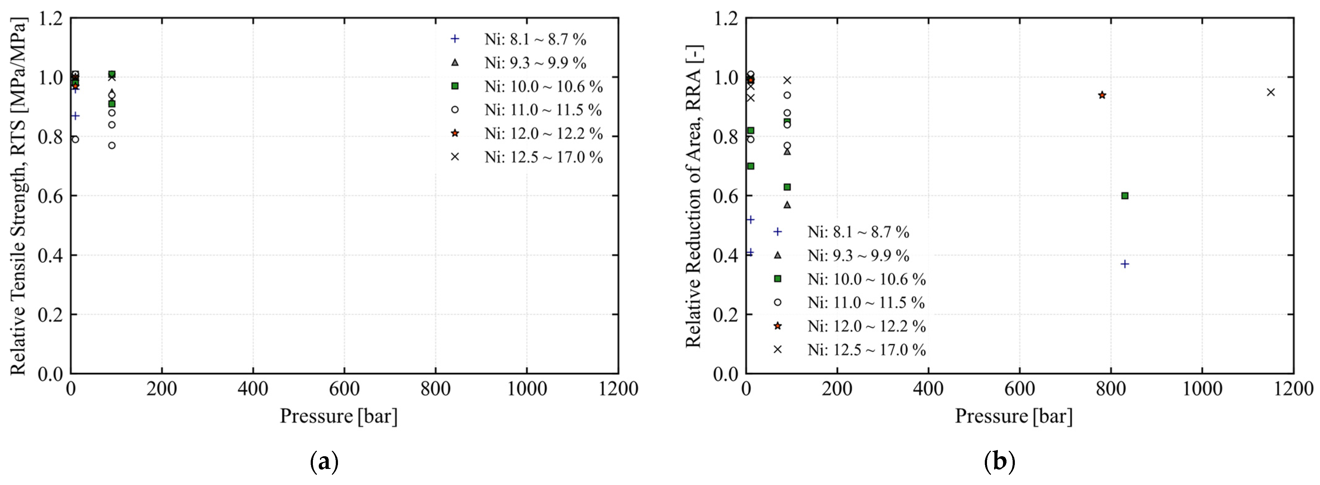
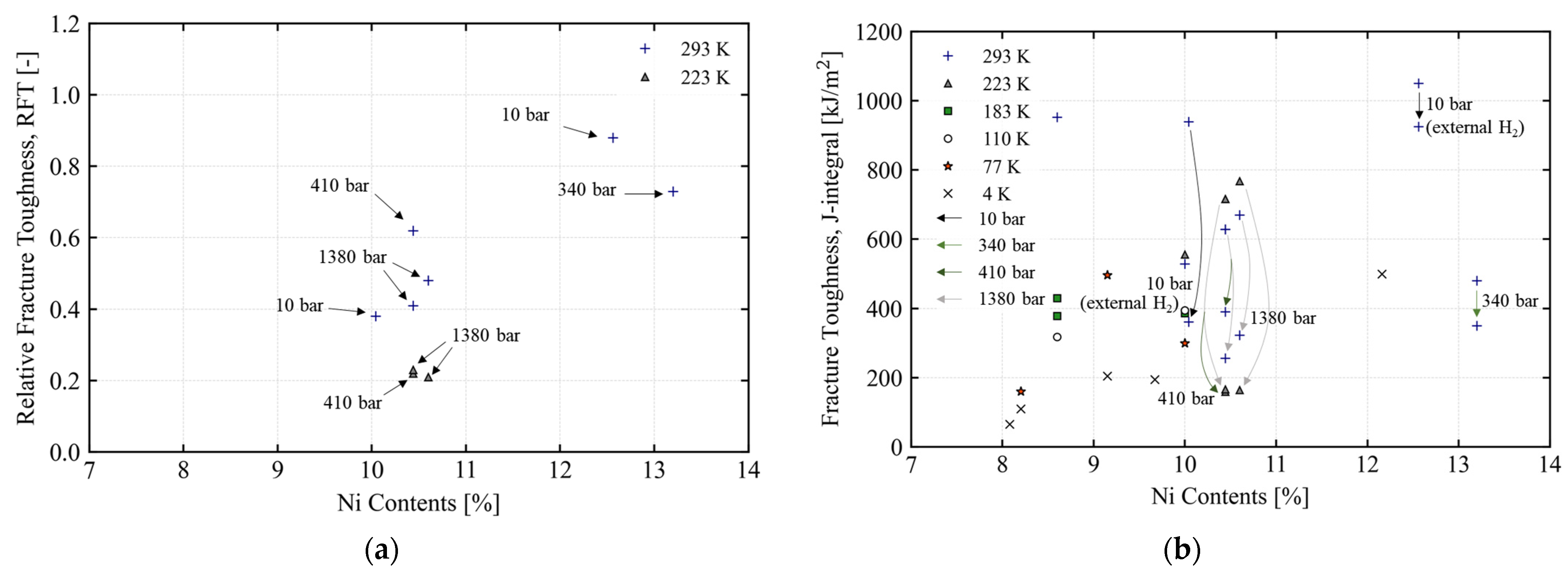
2.2. Effect of Hydrogen Embrittlement

Hydrogen embrittlement refers to the detrimental effects on metals exposed to hydrogen, leading to notable declines in their mechanical capabilities. This phenomenon encompasses numerous variables, which are broadly organized into three primary categories: environmental, material-based, and mechanical factors. From an environmental perspective, considerations include the surrounding temperature and pressure and specifics related to hydrogen, such as its purity, concentration, and duration of exposure. In terms of materials, factors encompass the material’s physical and mechanical attributes within the given environments, its microstructural attributes, and its surface conditions. Mechanically, it relates to the present stress conditions, the scale and regularity of stress alterations, notably fatigue, and inherent material flaws. These flaws might arise during manufacturing or from progressive structural cracks influenced by mechanical stresses and environmental factors. It is essential to meticulously assess these intertwined parameters, especially those unique to specific applications.
When hydrogen penetrates metals, its sensitivity is related to the reduction in critical stress required for crack initiation due to the trapping and accumulation of diffused hydrogen at specific locations within the metal [44,45,46,47]. To quantify the effect of the hydrogen environment, one can utilize the reduction in tensile strength and elongation as indicators, comparing tests conducted in ambient environments to those in a hydrogen environment. In many cases, quantifying hydrogen embrittlement involves the reduction in the tensile specimen’s area as yield strength remains unaffected and a hydrogen environment usually has less effect on tensile strength and elongation [48,49,50,51]. To quantitatively assess the change in cross-sectional area due to hydrogen effects, the relative reduction in area was used. The relative reduction in area (RRA) to assess the magnitude of the impact of hydrogen-induced cross-sectional area reduction is defined as follows.
R R A = R A H 2 R A r e f × 100 ( % )
R A H 2 indicates the reduction in cross-sectional area in a hydrogen environment, and R A R e f indicates the reduction in cross-sectional area after tensile tests in an ambient environment or gas environment without metal reactivity such as nitrogen, argon, and helium. In other words, the smaller the value of the relative cross-sectional area reduction, the greater the deterioration of mechanical properties due to the effect of hydrogen embrittlement. In order to quantitatively determine the degree of shrinkage of the cross-sectional area after fracture of a tensile test specimen, the reduction in area (RA) is defined as follows.
R A = A 0 A f A 0 × 100 ( % )
where A 0 is the cross-sectional area of the specimen before testing and A f is the cross-sectional area of the specimen after tensile testing.

2.2.1. Hydrogen Environment for Testing

There are two main ways to create an environment for hydrogen to penetrate and determine the extent of damage: applying a load in a hydrogen gas atmosphere and applying a load after hydrogen has already penetrated the specimen. These are called external and internal hydrogen conditions, respectively.
Testing under external hydrogen conditions is generally preferable due to its greater similarity to the target environment [52]. Performing tests in a hydrogen gas atmosphere typically requires a hyperbaric hydrogen chamber as required by ASTM G142. Hydrogen effects are most pronounced in hydrogen environments at slow strain rates and high pressures [53], and temperature also has a significant effect [54]. In a study by Sun et al. (2001), a strain rate-dependent tensile test using 304 L stainless steel with a nickel content of 9.11% in a gaseous hydrogen environment of 11 bar showed that at a strain rate of 4.2 × 10⁻² s−1, there was no effect of hydrogen [55]. At 10 times slower strain rate conditions, the relative reduction in area decreased sharply, which led to an increase in hydrogen influence.
In the internal hydrogen condition, metallic specimens are precharged with hydrogen first, and their mechanical performance is then evaluated. The effect of hydrogen on the deformation behavior of materials is fundamentally the same in external and internal hydrogen conditions [56,57,58]. Indeed, it is possible to find the same tendency in both conditions whereby the elongation decreases during a tensile test [48,59,60]. Thus, these internal hydrogen condition tests are currently widely employed because these methods are relatively safer and more cost-effective [61,62,63]. However, given that the achieved hydrogen content and distribution differ between the external and internal hydrogen conditions, the development of damage may vary depending on the hydrogen charging conditions [48].
The internal hydrogen condition is implemented mainly by thermal precharging and electrochemical recharging. Thermal hydrogen precharging is recommended for materials with low hydrogen diffusion coefficients [64].
Thermal hydrogen precharging is performed by exposing metallic specimens to high-pressure gaseous hydrogen at high temperatures of 200–350 °C. The increased temperature enhances the diffusion rate and solubility of hydrogen in austenitic stainless steel while having no significant effect on its microstructure. This allows hydrogen to be uniformly distributed through the entire specimen, and the amount of hydrogen charged can be precisely estimated based on the thermodynamic relationships [65,66].
Electrochemical hydrogen charging is a cathodic electrolytic method in which the hydrogen generated via electrochemical reactions at the cathode of the polarization system is forced into specimens. The amount of hydrogen charged into the metal specimen is affected by the fugacity of hydrogen, which refers to the activity of hydrogen. More specifically, the hydrogen fugacity is affected by the electrochemical potential [44,67,68]. It is possible to achieve an extremely high hydrogen fugacity near the specimen surface using cathodic electrolysis, and this leads to surface cracking and phase transformation [69]. Extensive research is currently underway to find methods for estimating the hydrogen concentration achieved by electrochemical hydrogen charging. However, it is difficult to predict and control the amount of hydrogen charged into specimens because this process involves various factors. Furthermore, as far as austenitic stainless steel is concerned, it is difficult to charge large amounts of hydrogen. The amount of hydrogen charged is 10 ppm or less when electrochemical hydrogen charging is performed according to ISO 16573–2: 2022 [70]. This level of hydrogen content is known to hardly affect the mechanical performance of austenitic stainless steel [71].
This limitation may be overcome by either increasing the hydrogen fugacity or raising the temperature of electrolyte solutions for enhanced reaction rates. The first method can be implemented by controlling the applied current, but the second method often leads to the evaporation of electrolyte solutions due to high-temperature conditions. Thus, most studies are currently focused on electrochemical hydrogen charging at room temperature.

2.2.2. Maximum Hydrogen Embrittlement Temperature

The test temperature affects the diffusion rate of hydrogen while it is penetrating and diffusing into a metal, having a direct effect on metallic defects. Accordingly, hydrogen embrittlement observed in metallic materials exposed to a gaseous hydrogen atmosphere is more pronounced within a specific temperature range [50,64,72]. In typical steel grades, hydrogen embrittlement is more pronounced at room temperature, and this is attributed to the mobility of hydrogen atoms. The temperature range for each material type that can be applied to low-temperature hydrogen atmospheres, in which hydrogen embrittlement is pronounced, is summarized below.
-
Nickel base alloys: Room temperature [73];
-
Carbon steel and low-alloy steel: 250–300 K [74,75];
-
Aluminum alloys: Room temperature;
-
Austenitic stainless steel (300–series Cr–Ni stainless steel): 200–220 K [72].
In carbon steel and low-alloy steel grades, hydrogen embrittlement occurs even at around 250 K, but it is typically observed over the entire room-temperature range. Thus, tests may be performed at room temperature. For aluminum alloys, it is recommended that tests be conducted at room temperature because they are hardly affected by hydrogen.
Austenitic stainless steels are most affected by hydrogen embrittlement around 220 K; at lower temperatures, strain-induced martensite transformation is promoted [76,77]. The diffusion rate of hydrogen in the martensitic phase is faster than in the austenitic phase [78,79,80], resulting in more damage than at room temperature by hydrogen embrittlement [81]. As the temperature decreases, the transformation to martensite is further promoted, but the mobility of hydrogen atoms is significantly slowed down below 200 K [82], which gradually reduces the effect of hydrogen embrittlement. In other words, austenitic stainless steels in which the strain-induced martensite transformation does not occur or is slowed down have a high resistance to hydrogen embrittlement. Han et al. (1998) performed a hydrogen sensitivity evaluation using temperature-dependent (295 to 80 K) tensile tests in a 10 bar gaseous hydrogen environment [83]. Metastable austenitic stainless steels of types 304 and 316 showed considerable HEE, but stable austenitic stainless steel of type 310S was not affected by the hydrogen environment. In stable austenitic stainless steel of type 310S with a nickel content of 20.21%, the transformation of the strain–induced martensite was not observed.
Figure 2 shows hydrogen susceptibility at low temperatures in a gaseous hydrogen environment (10 to 1380 bar) from previous studies [48,51,84,85,86,87,88]. The relative tensile strength is the ratio of the tensile strength of a tensile test in an atmospheric or inert gas environment to a tensile test in hydrogen. Since austenitic stainless steels fracture soon after reaching their tensile strength, a relative tensile strength in the range of 0.9 to 1.0 indicates that there is no significant reduction in tensile strength and elongation.
In a cryogenic environment below 20 K, various physical phenomena that are different from those observed at room temperature are observed. Many previous studies have reported that the effect of hydrogen embrittlement is insignificant in the temperature range close to the evaporation temperature of hydrogen. This is attributed to the reduced mobility of hydrogen atoms in a cryogenic environment, leading to changes in the thermal characteristics of metallic materials. In some studies in which tensile tests were performed at 20 K, however, the reduction in area ( R A ) was found to vary depending on the hydrogen conditions. Merkel et al. charged hydrogen into 304 L stainless steel specimens via thermal hydrogen precharging and created a cryogenic environment with a temperature of 20 K by cooling gaseous helium [87]. Under this condition, tensile tests were performed. At 20 K, the relative reduction in area ( R R A ) of the hydrogen-precharged specimens was found to amount to about 60% of that of the pristine specimens as a comparison group. A research team of Stuttgart University in Germany attempted to create a cryogenic environment for tensile tests by two methods, i.e., first, by directly exposing 304 LN and 316 LN stainless steel specimens to liquid hydrogen and, second, by cooling gaseous helium. The temperature was the same in both environments. The elongation of the specimens that were directly exposed to liquid hydrogen was 2–4% lower than that measured in the cryogenic environment achieved by using gaseous helium. The relative reduction in area was 61% and 77%, respectively [85].

2.2.3. Partial Pressure of Hydrogen

Hydrogen embrittlement is generally known to depend on the hydrogen pressure. Technically speaking, however, it is dependent on the partial pressure of hydrogen. Given that there is no such thing as 100% pure gas composed solely of molecules of the desired substance, it is generally recommended that high-purity hydrogen be used as a test gas. Koide et al. (2015) examined the effect of the partial pressure of hydrogen on the relative reduction in area ( R R A ) in 304 stainless steel and concluded that the effect of hydrogen was significant even at a pressure of 1 bar [89]. As the pressure increased, the R R A decreased, but the figure remained around 0.4. Figure 3 shows the evaluation of hydrogen susceptibility as a function of nickel content and hydrogen pressure from previous studies [48,51,84,85]. For nickel content of 10% or less, the reduction in tensile strength is very insignificant at hydrogen pressure conditions below 100 bar. At 400 bar around 220 K, the tensile strength is reduced by 40–60%. The hydrogen susceptibility decreases with increasing nickel content, and nickel content above 12% has a negligible effect on the tensile sensitivity even at low temperatures and 900 bar. This means that hydrogen pressure is primarily responsible for the material degradation of austenitic stainless steels, but hydrogen embrittlement becomes very insignificant at nickel contents above 12%.
Estimations based on the partial pressure of hydrogen in a mixed gas are likely to result in valid results, but it has recently been reported that even more accurate relationships can be obtained if one determines the hydrogen fugacity by considering the compressibility factors of other gases in the mix [90].

2.3. Effect of Material Characteristics

The body-centered cubic (bcc) structure of α′ martensite is inherently more susceptible to hydrogen-induced cracking than the face–centered cubic (fcc) structure in general, and it promotes hydrogen diffusion to accumulate in an embrittlement region at or near the crack tip [91,92]. The hydrogen embrittlement of hydrogen-charged stable austenitic stainless steels, in which no α′ martensitic transformation occurred during deformation, can be attributed to the low stacking-fault energy of the steels, because the low stacking-fault energy inhibits cross-slip and induces slip planarity [93].
Caskey observed that nickel addition decreased the temperature of the strain–induced martensitic transformation in iron-chromium-nickel stainless steels and that the HGE of the materials decreased markedly in the nickel composition range from 8% to 14% associated with an increase in austenite stability at room temperature [94]. The role of nickel is thus to improve both the stability of the austenitic phase and the resistance to HE; thus, the other alloy elements that promote the stability of the austenitic phase should improve the resistance to HE in general. It is reasonable to conjecture that strain-induced α′ martensite, to which the tendency of the transformation is dependent on nickel contents of the alloys, plays a key role in hydrogen-induced crack propagation in the alloys [50].
To assess the impact of nickel levels on hydrogen embrittlement, tensile tests were performed on Fe–(10–20)Ni–17Cr–2Mo alloys in hydrogen and helium environments at 1 MPa and temperatures ranging from 80 to 300 K. It was found that the HGE of the alloys below a nickel equivalent of 27% increased with decreasing temperature, reached a maximum at 200 K, and then decreased with further decreasing temperature, whereas no HGE occurred above the nickel equivalent of 27%. It was observed that the content of strain-induced α′ martensite increased with decreasing temperature and nickel equivalent, and hydrogen–induced fracture occurred mainly along the α′ martensite structure. Here, the nickel content of the specimen, which is the nickel equivalent of 27%, was 12.90%.
San Marchi et al. (2010) conducted tension tests on seventeen metastable austenitic stainless steels, including type 304 and 316 alloys, under both internal and external hydrogen exposure [48]. For relative reduction in area >0.5, the tensile strength is essentially unchanged for materials tested in external hydrogen, while the tensile strength is increased by 5–10% for materials with internal hydrogen. For relative reduction in area < 0.5, the basic trend between R R A and R T S is similar for external and internal hydrogen: R T S is lower for lower values of R R A . The relative tensile strength is the ratio of the tensile strength of a tensile test in an atmospheric or inert gas environment to a tensile test in hydrogen
For materials selection, it is informative to establish bounds on nickel content using this fracture-based metric. At 223 K, the lower–bound nickel content for these alloys is established at 12.5 wt% (i.e., R R A = 0.5) for the most severe hydrogen conditions that are reported here (Figure 3). For ambient temperature applications, a similar construction (Figure 2) shows that the lower–bound nickel content is nearer 10 wt% (i.e., R R A = 0.5). While this criterion ( R R A > 0.5) is somewhat arbitrary (since it does not address specific requirements or performance of engineering design), it represents a step toward more comprehensive, mechanistic assessment of the resistance of metals to hydrogen–assisted fracture using simple test methods such as tensile testing.
Matsuoka et al. (2015) conducted a study to examine the criteria used to identify hydrogen embrittlement (HE) in austenitic stainless steels, specifically types 304, 316, 316 L, and 316 (hi-Ni). The study aimed to understand the mechanism behind hydrogen–assisted surface crack growth (HASCG) by conducting a variety of tests, including SSRT, JIC, FCG, and fatigue life, on these steels. These tests were conducted under hydrogen gas pressures ranging from 78 to 115 MPa and at temperatures ranging from −40 °C to room temperature (RT) [84]. The austenitic stainless steels that meet R R A ≥ 0.68 ensure that there is no reduction in tensile strength. As a result, types 316 L and 316 (hi-Ni) can be used in hydrogen gas at pressures of ≤15 MPa and temperatures ranging from −40 °C to RT. Ductile crack propagation is expected in austenitic stainless steel as hydrogen–induced local slip deformations occur near the crack tip as opposed to brittle crack propagation. As a standard measure, it was proposed that the elongation and reduction in area in a hydrogen atmosphere must be 0.1 or higher. In accordance with this recommendation, types 304, 316, 316 L, and 316 (hi-Ni) are suitable for use in hydrogen gas at pressures ≤115 MPa and temperatures ranging from −40 °C to RT.

2.4. Effect of Testing Method

The effect of the test temperature on the degree of hydrogen embrittlement may not be universally applied to all mechanical performance tests. Hydrogen sensitivity is mainly evaluated by the SSRT, and thus, the specific explanations discussed above may apply better to tensile tests. Fatigue life tests at low temperatures genially exhibit improved results, and even if tests are performed in a hydrogen atmosphere, similar results are obtained [61,76,95,96,97]. In this regard, ANSI/CSA CHMC–1 and SAE J2579 require that fatigue performance tests be performed at room temperature [98].
In a hydrogen atmosphere, fatigue crack growth in stainless steel is accelerated, and this process is significantly affected by the frequency of the applied load. Once fatigue cracking is initiated in austenitic stainless steel, austenite-to-martensite transformation occurs at the tip of each crack. The diffusion rate of hydrogen is higher in martensite than in austenite, and thus, martensite is less resistant to hydrogen-induced cracking [99]. Accordingly, the load frequency should be low enough to ensure the diffusion of hydrogen after the completion of phase transformation at the tip of each fatigue crack.
In a previous study, specimens welded to stainless steel plates (304 L and 316 L) were precharged with hydrogen, and their fracture toughness was evaluated based on the J-R curves obtained at low temperatures. The researchers confirmed that their resistance to crack growth was significantly reduced at a low temperature of −40 °C compared to when tested at room temperature [100].
Figure 4 shows the effect of hydrogen conditions and test temperature on fracture toughness from previous studies [23,24,25,26,27,28,29,30,91,101]. The relative fracture toughness is the ratio of the fracture toughness measured in an atmospheric or inert gas environment to fracture toughness measured in a hydrogen environment. Except for the test performed in a gaseous hydrogen environment at 10 bar, all other tests were performed at the target temperature using a thermally precharged specimen with hydrogen. The fracture toughness was significantly impacted by temperature and Ni content. More research is required to determine the impact of hydrogen precharging conditions.

3. Comparison of LNG and LH2 System for Ships

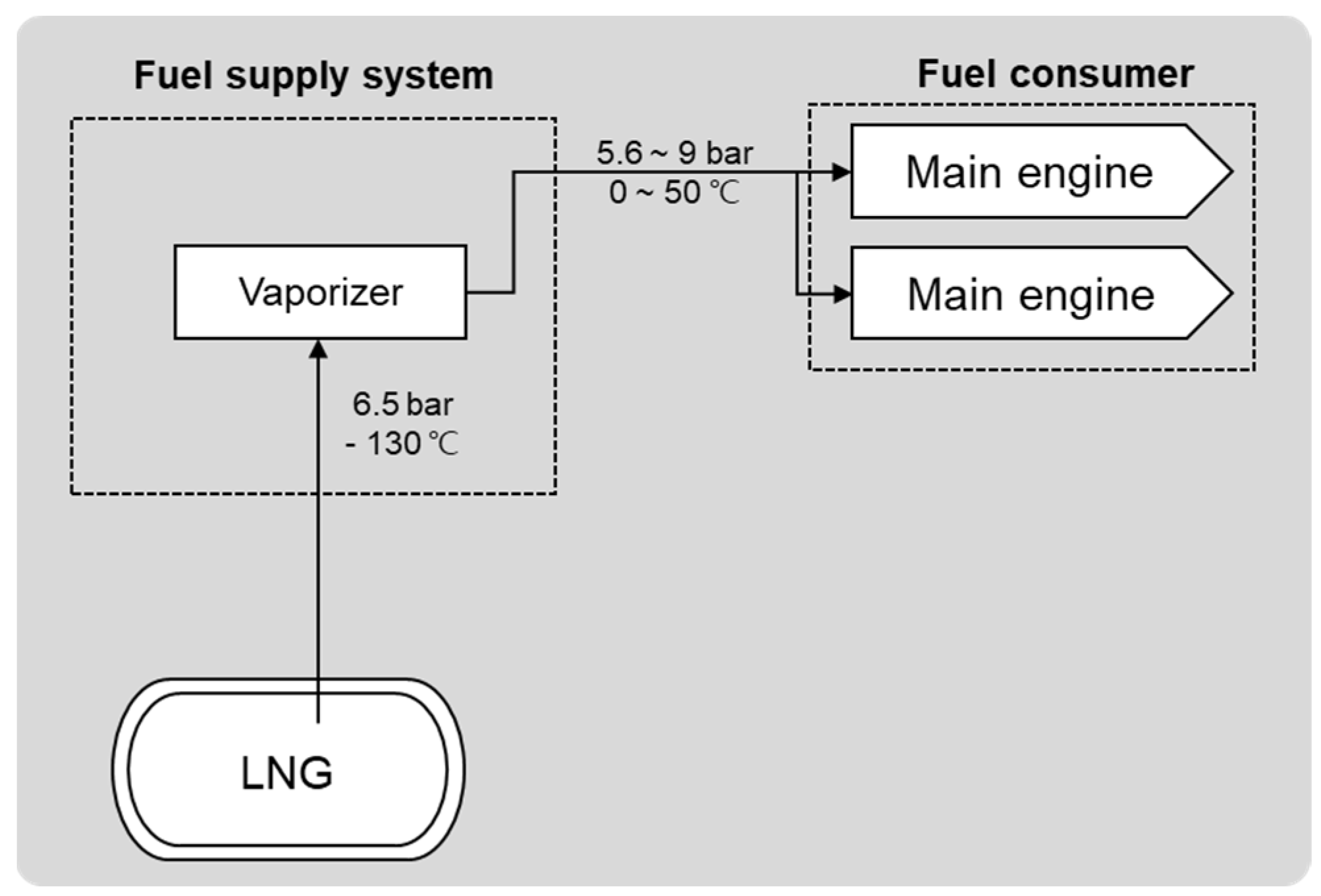
3.1. System Configuration

This section outlines the temperature, pressure, and other conditions for fuel containment, piping, and fuel consumption sources for ships powered by LNG and liquid hydrogen. From these conditions, the design requirements for each system are derived.
Figure 5 presents a schematic representation of the LNG-based low-pressure fuel supply system. In general, this system is composed of a fuel containment facility, a fuel supply system, and fuel consumption sources (e.g., internal combustion engines). LNG is stored at a temperature of −163 °C or below, and the design pressure may vary depending on the type of tank used. LNG is kept at a temperature of about −130 °C and a pressure of 6.5 bar while being fed to the vaporizer among the key components of the fuel supply system. Engines and boilers for propulsion and power generation are generally used as fuel consumers. The fuel supply system allows a gaseous fuel at 0–50 °C to be supplied at a pressure of 5.6–9 bar in a gaseous state to the fuel consumer in which it is consumed.
Figure 6 presents a schematic representation of the fuel supply system that is generally applied to hydrogen fuel cell-fueled ships based on liquid hydrogen. This system is composed of a liquid hydrogen tank, fuel supply system, and fuel consumer (e.g., fuel cells). Within each part of this system, hydrogen exists in various forms. Liquid hydrogen is stored in a tank at a temperature of −253 °C and fed to the fuel consumer via the fuel supply system. In general, the fuel supply system is composed of two heat exchangers, a compressor, and an LP heater. It is supplied to the heat exchangers in the state of either liquid or gas. From the liquid hydrogen tank, gaseous hydrogen is transported to one heat exchanger at −240 °C and 2 bar, while liquid hydrogen is transported to another heat exchanger at −245 °C and 4 bar. Afterward, the liquid hydrogen is converted into a gaseous form at the heat exchanger and then supplied to the LP heater while being kept at 4 bar and −10 °C. Finally, the liquid hydrogen is supplied by the LP heater to the fuel cell in a gaseous state at 1~2 bar and −20~50 °C. The fuel cell generates power by consuming the gaseous hydrogen to power the ship via the ECU, converter, and main propulsion motor.
Currently, there are no standards available for the design pressure and maximum allowable working pressure of the hydrogen storage and transport system equipped in liquid hydrogen carriers and liquid hydrogen-fueled ships. Safety regulations on land–use liquid hydrogen systems, which are operated under hydrogen conditions similar to those illustrated in the schematic diagram of Figure 6, are summarized, along with relevant R&D activities, in Table 1.
Liquid hydrogen containers are known to be designed to have a pressure level of 1–10 bar. The CGA H-3 (Standard for Cryogenic Hydrogen Storage) of the Compressed Gas Association (CGA) limits the maximum allowable pressure to the level of 150 psi (≒10.3 bar), and the Sandia National Laboratory also applied the same maximum allowable pressure to liquid hydrogen-fueled ships in its feasibility study [102,103]. Kim et al. (2021) attempted to propose a methodology for determining the design pressure of liquid hydrogen storage tanks that can be applied to liquid hydrogen terminals. To that end, the researchers developed specific operation scenarios and performed a series of thermal and structural analyses based on them. The maximum pressure reached during the import of liquid hydrogen to the storage tank was 197.9 kPa, and the design pressure was defined as 220 kPa, considering the hydrostatic pressure [104]. In practice, in GODU-LH2 (Ground Operations Demonstration Unit), a project executed to verify the liquid hydrogen zero boil-off technology of NASA, the design pressure of a container with an internal capacity of 125,000 L (125 m3) was found to be 95 psig (≒6.55 bar) [105].
Table 1. Operating conditions for the hydrogen system.
TargetCategoryPressure (bar)Temp. Range (K)Ref.
GODU–LH2 projectDesign pressure of the inner tank6.55Abt. 20[105]
LH2 terminalDesign pressure of the inner tank2.2Abt. 20[104]
CGA StandardMAWP of the inner tank10.3Abt. 20[103]
LH2 tankMAWP of the inner tank9.0Abt. 20[106]
PEMFCMAWP of the inlet≤3.5Ambient[106]
CGH tankMaximum fueling pressure≤875233 to 358SAE J2579
Before the normal operation starts, liquified gas is imported into liquified gas cargo or fuel tanks via the sequential process of drying, inerting, gassing up, and cooling down. In the gassing-up process, the inert gas contained in the tank is replaced by a gas of room temperature, and this process is followed by cooling down to prevent any damage due to a sudden temperature change. Here, the inside of the liquid hydrogen storage container may have different temperature distributions, ranging from 20 K, the evaporation temperature of liquid hydrogen, to 300 K, room temperature, depending on the position, and the pressure is expected to be 10 bar or lower.
The temperature range of the piping system may be wide, from 20 to 300 K, because it should be able to properly transport liquid hydrogen and gaseous hydrogen from the fuel tank to the fuel consumer. The maximum pressure was assumed to be 10 bar, which was the same as that of the storage container. At the CCC’s 8th conference, Norway proposed a requirement that the design pressure of liquid hydrogen supply and bunkering pipes be at least 20 bar, but further discussion is still needed on this issue. Accordingly, in this document, a review was performed while assuming that the design pressure was 10 bar or lower.

3.2. System Minimum Requirements

Natural gas in a gaseous or liquid state is colorless, odorless, non-toxic, and non-corrosive. It is stored in a liquid state at a pressure of up to 10 bar in cargo or fuel containment systems. Risk factors related to LNG that affect the selection of system materials, as well as measures to reduce such risk factors, are as follows.
  • Risk factors related to LNG
    -
    Cryogenic burns;
    -
    Low-temperature embrittlement;
    -
    Risk of suffocation;
    -
    Expansion and pressure;
    -
    Fire;
    -
    Rapid phase separation (evaporation).
  • Measures to reduce risk factors
    -
    Protection from external environments (cofferdams, airlocks, etc.);
    -
    Pressure relief and ventilation;
    -
    Secondary sealing (e.g., dual tubes and secondary barriers);
    -
    Application of welded connections rather than flange connections;
    -
    Drip tray capacity and liquid detection;
    -
    Protection of the hull structure from released cryogenic, high-pressure steam and gas.
The cargo and fuel containment systems specified in the IGC/IGF codes are required to be equipped with secondary full-liquid-tight barriers to safely contain any released fluid and must also be able to prevent the temperature of the hull structure, along with insulation facilities, from going below a critical level. If the possibility of structural damage and fluid leakage through the primary barrier is extremely slight or virtually zero, as in Independent Tank Type C, no secondary barriers are required for containment facilities for liquefied gas fuels. However, for independent tanks that require the installation of full or partial secondary barriers, additional measures to safely handle any possible leakage from tanks are required. In addition to the process facilities, as illustrated in Figure 5, drip trays may be additionally required depending on the type of tank used. Drip trays must be properly installed in places where any possible leakages that may damage the overall hull structure may occur. Suitable materials must be used to bear the low temperature of leaked liquified gas, and thus, aluminum alloys or austenitic stainless steel alloys are generally used.
The piping system requires the design pressure to be equivalent to or higher than the atmospheric pressure so that liquified gas cargoes and fuels can be properly transported and supplied. Accordingly, it is important to use materials with sufficiently high strength and ductility even in a low-temperature environment. It is also necessary to determine whether the diameter and thickness of pipes are suitable for a given design pressure.
Gaseous hydrogen is colorless, odorless, and highly penetrating because its molecules are very light and small, and thus, it is able to easily pass through leakage paths while rapidly diffusing out into the surrounding environment. Hydrogen, once penetrating into a metal, diffusing, and accumulating in specific parts, reduces the critical stress level above which cracking occurs, thereby degrading its mechanical properties, including strength and elongation. Liquid hydrogen has a light blue hue. When exposed to the atmospheric environment, it will rapidly start to evaporate. In case of other gases being directly exposed to liquid hydrogen, they may be solidified, damaging the overall system. Risk factors related to hydrogen that affect the selection of materials, as well as measures to reduce such risk factors, are as follows.
  • Risk factors related to hydrogen
    -
    Combustion-related factors: low ignition energy, a wide range of combustion conditions, less visible flame, and fast flame propagation;
    -
    Low temperature-related factors: low-temperature burns, oxygen enrichment by liquefaction/condensation, solidification of other fluids;
    -
    High permeability;
    -
    Low viscosity;
    -
    Hydrogen embrittlement in parent materials and weld metals.
  • Measures to reduce risk factors (focused on hydrogen embrittlement)
    -
    Reduction in working stress (to the level of 30–50% of yield strength) [107];
    -
    Minimization of low-temperature plastic deformation during cold working (estimated while considering all generated stress);
    -
    Solution heat treatment recommended for stainless steel;
    -
    Carbon steel pipes heat-treated by normalizing;
    -
    Alloy steel with a tensile strength of 950 MPa or less treated by quenching and tempering;
    -
    Seamless steel pipes used in a high-pressure hydrogen environment with a pressure level of 200 bar or more;
    -
    Flange connection methods avoided when connecting pipes if weld joints can be applied;
    -
    Full penetration butt weld.
The risk reduction measures described above were prepared by summarizing the details of international safety standards on the use of hydrogen. When it comes to the operation of the liquid hydrogen storage and supply system, its cryogenic properties, along with hydrogen permeability and embrittlement, must be thoroughly reviewed. For example, carbon steel may be used to a limited extent in a certain hydrogen environment, but it cannot be used in a temperature range below its ductile-brittle transition temperature. In addition to the previously mentioned mitigation measures, additional methods are available to prevent the diffusion of hydrogen atoms and avoid adverse impacts on the mechanical properties of materials [108,109,110]. Well-known hydrogen barriers include graphene and alumina. Most research focuses on diffusion prevention, making it difficult to achieve effective hydrogen blockage due to issues such as coating wear and delamination.
The IMO’s independent tank types are preferred as liquid hydrogen cargo and fuel containment systems because they are effective at minimizing heat transfer from the external environment. The liquid hydrogen storage and transport system using independent tanks equipped in ships requires the following facilities in addition to the ones described in Figure 6.
-
Cargo/fuel tanks and pressure vessels for processes;
-
Piping system for cargo/fuel and processes;
-
Drip trays;
-
Outer shells.
The IMO’s Independent Tank Type C for LNG storage does not require the installation of drip trays and secondary barriers, but in places where leakage may possibly occur, drip trays are required to prevent damage to the hull structure. Any fuel supply pipes that pass through enclosed spaces or gas safety zones in the ship must be mechanically ventilated or composed of dual tubes pressurized with inert gas. These requirements aim at preventing the risk of gas leakage.
Dual vacuum insulation must be applied to liquid hydrogen storage containers and piping systems in accordance with numerous international safety standards, unlike in the cases of LNG applications. In the case of adopting mechanical ventilation or applying inert gas, the air or inert gas may be liquified or solidified due to the very low temperature of liquid hydrogen. Furthermore, achieving reliable insulation performance requires a dual vacuum insulation structure.
The inner walls and surface of liquid hydrogen storage containers and piping systems remain constantly exposed to low-temperature liquid hydrogen or a low-temperature hydrogen atmosphere at all times, and thus, these parts must be sufficiently resistant to low temperatures and hydrogen penetration. The outer shells of liquid hydrogen storage containers and piping systems are separated by a vacuum layer and thus not exposed to a hydrogen atmosphere during normal operations. Even in case of leakage, they are exposed to hydrogen for a relatively short period of time due to the rapid evaporation of liquid hydrogen and forced ventilation. Therefore, a significantly high resistance to hydrogen embrittlement is not required. Similarly, drip trays are exposed to hydrogen only during abnormal operations, e.g., in case of leakage of liquid hydrogen, and thus do not have to be highly resistant to hydrogen embrittlement.

3.3. Applicable Materials

According to the IGF/IGC codes, applicable metallic materials for LNG containment systems are as below. At temperatures lower than the design temperature of LNG storage and supply systems, these metallic materials are considerably ductile and do not exhibit a ductile–brittle transition temperature (DBTT), demonstrating that they are highly stable.
-
9% nickel steel;
-
Austenitic stainless steel: AISI 304, 304 L, 316, 316 L, 321, 347;
-
Aluminum alloys: Al 5083;
-
Austenitic Fe-Ni alloy steel: 36% nickel steel;
-
Cryogenic high-manganese steel.
When necessary, corrosion resistance tests and impact tests may be required by the Korean Register of Shipping, depending on the purpose of use of the structural steel of interest, but given that LNG is a non-corrosive fuel, corrosion resistance tests are not required. According to Chapter 7 (Materials and Tube Design) of the Korean Register of Shipping’s regulations on ships using low flash–point fuels (Table 7), impact tests may be omitted for austenitic stainless steel alloys upon approval from the Korean Register of Shipping. This is because it has been verified to exhibit sufficiently high impact toughness at the test temperature of −253 °C, which is a condition achieved by cooling it using liquid helium [42].
Low-temperature applicability is the most important requirement for materials used for the LNG storage and transport system, but materials for liquid hydrogen facilities are additionally required to be suitable for the hydrogen atmosphere. Accordingly, according to historical safety regulations, including ISO/TR 15916, among materials that are applicable at the target temperature, those with excellent resistance to hydrogen are selected. These materials can be classified according to their sensitivity to hydrogen as follows [111].
  • Category 1: Materials that are almost not affected by hydrogen embrittlement under limited conditions;
  • Category 2: Materials that undergo hydrogen embrittlement and thus can only be used under limited conditions;
  • Category 3: Materials that are significantly affected by hydrogen embrittlement, for example, ending up failing or breaking, in an elastic range in which the stress is lower than the yield strength of the material.
Those that fall into Category 1 include aluminum alloys (Al 6061-T6) and austenitic stainless steel alloys (300 Series Stainless Steel). Not all austenitic stainless steel grades fall into this category. It has been found that if the Ni content is 12.5% or more, their mechanical properties are not affected even in an environment highly prone to hydrogen embrittlement [49,51]. ASME BPVC specifies that materials applicable to a high-pressure gaseous hydrogen environment with a pressure level of 1030 bar or less include alloy steels, including SA-372 and SA-723; stainless steel, including SA-336 Gr. F316; and aluminum alloys, including Al 6061-T6 (refer to Code Case 2938).
Those that fall into Category 2 include stainless steel and carbon steel in addition to stable austenitic stainless steel grades. Different safety standards (KGS FU671: 2021, CGA G-5.6 (2005), and CGA H-5 (2020)) specify that some carbon steel grades may be used if the partial pressure of hydrogen is 10 bar or less. It is also recommended that metastable stainless steel that may undergo transformations, ferritic stainless steel, martensitic stainless steel, duplex stainless steel, and precipitation-hardened stainless steel be only used in parts with low operating stress. As such, the operating stress is limited to a certain level because hydrogen embrittlement occurs when the three conditions regarding material, environment, and stress are all satisfied at the same time.
Among austenitic stainless steel grades, 316 L with the highest Ni content could be the safest choice for hydrogen-atmosphere applications, but applying 316 L to all components of the system that are exposed to gaseous hydrogen is considered a very conservative approach to material selection. As summarized in Section 3.1, the liquid hydrogen containment and piping systems of ships are exposed to hydrogen at low temperatures (20–300 K) and relatively low pressures (1–10 bar); this condition is considered to be moderate from a hydrogen embrittlement perspective compared to a high-pressure gaseous hydrogen atmosphere. More cost-effective materials, such as metastable austenitic stainless steel grades, may be selected and applied through material compatibility assessments considering various conditions, including temperature and the partial pressure of gaseous hydrogen.

4. Analysis of Safety Regulations for Material Selection

4.1. General Considerations in Material Selection

4.1.1. ISO/TR 15916

ISO/TR 15916 (Basic considerations for the safety of hydrogen systems) is one of the most fundamental safety standards for systems that handle hydrogen in a liquid or gaseous form [8]. The standard defines basic safety considerations and risks. The interim guidelines on hydrogen carriers and hydrogen-fueled ships currently under discussion by the Sub-committee on Carriage of Cargoes and Containers of the International Maritime Organization have also been developed and reviewed with reference to this standard. This section analyzes other safety standards for pressure vessels, cylinders, and piping systems for liquid and gaseous hydrogen storage, similar to ISO/TR 15916, especially with regard to material restrictions and material recommendations for different temperatures and hydrogen atmospheres.
ISO/TR 15916 defines different risk factors related to the hydrogen system. The standard specifies that among various risk factors, low temperature and hydrogen embrittlement may pose significant damage, but these risk factors can also be addressed by proper design and material selection. Hydrogen attack mainly occurs at temperatures higher than 200 °C, and thus, this phenomenon is not considered in the design of liquid hydrogen storage systems. The standard states that the following factors must be considered for the selection of materials suitable for a given hydrogen application and exposure condition: temperature, hydrogen embrittlement, permeability, porosity, and compatibility between different metals.
Here, the term ‘temperature’ mainly refers to low-temperature conditions. Given that most materials tend to shrink, and their ductility and specific heat are reduced when cooled down to the temperature of liquid hydrogen, sufficient toughness must be ensured at low temperatures. Charpy impact tests are among the simplest test methods for low-temperature toughness. This test aims to confirm that the ductile-to-brittle transition temperature (DBTT) of the tested material is lower than the target temperature. Here, the temperature difference between the air and liquid hydrogen is as large as 280 K, and thus, any heat stress that may arise from thermal expansion and contraction must also be considered. Thermal shrinkage resulting from the temperature difference between atmospheric and cryogenic conditions is known to be 0.3% for steel alloys and 0.4% or more for aluminum.
Measures to address hydrogen embrittlement may be divided into (1) those focused on design and structural aspects and (2) others focused on material characteristics, as follows.
  • Design and structural aspects
    -
    Reduction in operating stress levels;
    -
    Minimization of low-temperature plastic deformation during cold working;
    -
    Avoidance of repetitive loading to prevent fatigue cracks.
  • Material aspects
    -
    Constraints on the hardiness and strength of metallic materials;
    -
    Minimization of residual stress;
    -
    Application of materials with excellent resistance to hydrogen, e.g., austenitic stainless steel;
    -
    Assessments based on ISO 11114-4 in material selection.
Appendix C of ISO/TR 15916 provides a table that categorizes materials according to their sensitivity to hydrogen embrittlement. The major details are summarized in Table 2, which are also consistent with the content described in ASME B31.12 and ANSI/AIAA G-095A-2017.

4.1.2. KGS Code

The Korea Gas Safety Code (KGS Code) presents a systematic, detailed description of the technical matters specified in gas-related laws and regulations based on specific criteria, especially with respect to facility, technology, and inspection aspects. This technical standard was approved by the Ministry of Trade, Industry and Energy upon deliberation and resolution by the Gas Technical Standard Committee. This standard was enacted to streamline the existing complex procedure for legislative enactment and revision, thereby ensuring the safety of the general public in the use of gas. This code is applied based on the three acts on gas (High-Pressure Gas Safety Control Act, Safety Control and Business of Liquefied Petroleum Gas Act, and Urban Gas Business Act), along with the Hydrogen Economy Promotion and Hydrogen Safety Management Act. This code defines specific restrictions and technical/facility standards that must be applied in the manufacturing of vessels (containers, refrigerators, and other specific facilities), gas consumers, and other gas-related equipment or in the operation of facilities that treat gases (charging, producing, selling, supplying, storage, and utilization). Liquid hydrogen is related to the part of the KGS Code regarding the use of hydrogen and high-pressure gases. The following three specific codes were found to provide detailed standards for materials considering cryogenic conditions (with a liquefaction temperature of −253 °C) and fuel characteristics (hydrogen and high-pressure gases).
-
KGS AC111 2021 (Code for Facilities, Technology and Inspection for Manufacturing of High-Pressure Gas Storage Tanks and Pressure Vessels);
-
KGS AC213 2021 (Code for Facilities, Technology and Inspection for Manufacturing of Cryogenic Cylinders);
-
KGS FU671 2021 (Facility/Technical/Inspection Code for Use of Hydrogen Gases).
Most details of the KGS Code are referenced to the ASME Code. The major details and characteristics of each code, except for structure-related descriptions (structure thickness estimation, supports, etc.), are as follows.
(1)
Major Details of KGS AC111: 2021
KGS AC111 applies to the facilities, technology, and inspection that are employed for the manufacturing of storage tanks and pressure vessels, except for LNG storage tanks. The term “pressure vessel” refers to a container with a design pressure of 2 bar or more for liquified gas and 10 bar or more for compressed gas at 35 °C. Hydrogen embrittlement resistance tests may be required for pressure vessels operated at a temperature of 95 °C or less if the partial pressure of hydrogen with respect to the design pressure is 52 bar or more. This threshold may vary depending on the material type. This hydrogen embrittlement resistance assessment is performed by a series of tests, including SSRT, fracture tests, fatigue fracture tests, and fatigue tests, to determine the service life of materials.
The upper and lower limits of temperatures and tensile stress for materials are estimated (in the same manner as specified in ASME BPVC) based on the maximum allowable tensile stress levels for each temperature range specified in Appendix A (Maximum Allowable Tensile Stress for Steel Materials). Appendix B defines suitable impact test methods for each material type while also considering the test temperature and specimen thickness, but the test temperature range is defined to be up to −196 °C.
(2)
Major Details of KGS AC213: 2021
KGS AC213 applies to the facilities, technology, and inspection that are employed for the manufacturing of vessels intended for charging liquified gas with a temperature of −50 °C; however, a hydrogen atmosphere is not considered. Here, allowed materials will be limited to austenitic stainless steel alloys or aluminum alloys (5052, 5083) for safety purposes.
The material acceptance criteria for austenitic stainless steel include elongation-tensile strength measurements and squeeze test results. Tensile tests are performed according to KS B 0802 (Method of Tensile Test for Metallic Materials), and the elongation of the tested material must be in the range of 15–30%. Squeeze tests are performed on vessels after specific heat treatments. At the onset of cracking, the distance between the two wedges must not be more than eight times the thickness of the vessel shell.
Among aluminum alloys, 5082 and 5083 grades must have a tensile strength of at least 176–265 N / mm 2 with an elongation of at least 15–18%. In squeeze tests on these alloys, at the onset of cracking, the distance between the two wedges must not be more than 8.7 times the thickness of the vessel shell, similar to the cases of austenitic stainless steel.
Appendix A also presents material characteristic curves that can be used to estimate the properties of a cylindrical or spherical shell under external force, especially with regard to various materials, including austenitic stainless steel and aluminum alloys.
Materials for welded joints must be verified for compatibility in terms of the following items.
-
Tensile tests for welded seams: in terms of tensile strength/yield strength;
-
Bending tests for the inside of the welded joint: in terms of the amount of cracking;
-
Bending tests for the side of the welded joint: in terms of the amount of cracking;
-
Bending tests for the backside of the welded joint: in terms of the amount of cracking;
-
Tensile tests for the used weld metal: in terms of tensile strength/yield strength, with an elongation of 22% or more;
-
Impact tests for welded joints (applied only to stainless steel): in terms of impact absorption energy, measured by Charpy impact tests at −150 °C or less (with an impact absorption energy of at least 20 J/cm2 and 30 J/cm2 or more on average.
(3)
Major Details of KGS FU671: 2021
KGS FU 671 applies to the facilities, technology, and inspection of systems that use hydrogen as fuel. These systems include hydrogen facilities, including those used for hydrogen production and storage, as well as other gases and supplies. Applicable materials include those with specific mechanical properties and chemical compositions that suit the nature, temperature, and pressure of hydrogen.
If the hydrogen pressure is 10 bar or more, any material used should be regarded as a material for high-pressure piping systems. Thus, any materials with mechanical properties and chemical compositions equivalent or superior to those required for such material may be selected and used. If the hydrogen pressure is 10 bar or less, any material used should be regarded as a material for low-pressure piping systems. Thus, any materials that fulfill the requirements specified in KS D 3631 (Carbon Steel Pipes for Fuel Gas Piping) may be selected and used. The chemical composition requirements are presented in Table 3, and the requirements for mechanical properties are omitted here because they vary depending on the material thickness. The material specifications corresponding to materials for high-pressure and low-pressure piping systems are specified in the KGS Code. Any material that meets its material specifications may not be used beyond the temperature range that corresponds to the allowable stress of the material, and Appendix A of KGS AC111 may be referenced. Other materials that are equivalent or superior must meet the requirements for Charpy impact tests at the design temperature. The minimum allowable absorption energy may vary depending on the tensile strength and thickness of the parent material.

4.1.3. CGA Standard

The Compressed Gas Association (CGA) works for the enactment and dissemination of technical safety standards for the manufacturing, storage, transport, and supply of compressed, liquefied, and cryogenic gases while engaging in R&D activities to improve the quality of compressed gases while developing relevant technologies. As it currently stands, researchers in private-sector businesses, such as the American Society of Mechanical Engineers (ASME) and the American Petroleum Institute (API), are in charge of gas safety management based on collaboration with universities and government agencies. The following parts of the CGA Standard provide important safety standards for liquid hydrogen storage systems.
-
CGA H-3 (2019) Standard for Cryogenic Hydrogen Storage;
-
CGA H-5 (2020) Standard for Bulk Hydrogen Supply Systems;
-
CGA G-5.4 (2019) Standard for Hydrogen Piping System at User Locations;
-
CGA G-5.6 (2005) Hydrogen Pipeline Systems.
(1)
Major Details of CGA H-3 (2019)
CGA H-3 applies to liquid hydrogen storage vessels (with a design temperature range between −253 and 38 °C) with a gross volume of 3.8–94.6 m3 and a maximum allowable working pressure (MAWP) of 12.1 bar or less. Aluminum alloys are not recommended as materials for the inner vessel because their thermal conductivity and coefficient of thermal expansion are significantly larger than those of stainless steel. Similarly, 9% nickel steel alloys are not considered suitable for the inner vessel due to their low ductility.
Only full penetration butt welding may be applied to the inner vessel, and any corrosion allowance is not considered; thus, 300-series austenitic stainless steel alloys are mainly used for the inner vessel according to the ASME Boiler and Pressure Vessel Code. Austenitic stainless steel alloys are required to be subjected to solution heat treatment to reduce the generation of residual stress during cold working.
Steel may be used as a material for the outer jacket. Material selection and design for any pipes connected to pressure vessels are conducted according to ASME B31.12 (Hydrogen Piping and Pipelines). There are many measures available to minimize the occurrence of hydrogen embrittlement in piping systems.
-
All annular-space pipelines must be composed of seamless tubes or pipes made of austenitic stainless steel.
-
Welding on tube or pipe connections should be avoided as much as possible, and if unavoidable, butt welding should be used.
-
For 304 stainless steel, it must be ensured that any stress that exceeds 20% of its tensile strength is not generated. Here, any stress generated during cold working should also be counted in the estimation process.
-
The 316 stainless steel is a material with excellent resistance to hydrogen embrittlement.
(2)
Major Details of CGA H-5 (2020)
CGA H-5 applies to liquid and gaseous hydrogen fuel supply systems with a capacity of 141.6 m3 or more for gaseous hydrogen and 150 L or more for liquid hydrogen. The maximum allowable working pressure is 1034 bar.
Liquid hydrogen is a cryogenic liquid, and high-strength steel is generally susceptible to hydrogen embrittlement; thus, low-strength carbon steel is more suitable. Hydrogen embrittlement causes vessels to be damaged even under a stress that is significantly lower than the yield stress of the material used. Accordingly, the risk of hydrogen embrittlement must be thoroughly reviewed, especially in welded areas. Low-strength carbon steel is hardly affected by hydrogen in a gaseous hydrogen atmosphere (with a pressure of 10 bar or less) at room temperature. However, when the hydrogen pressure is 25 bar or more, the effect of hydrogen embrittlement is pronounced, and thus, the use of each material may be limited depending on the given pressure conditions.
Drip trays for liquid hydrogen storage vessels are supposed to collect the condensed air. Therefore, they must be installed under pipelines. Drip trays are mainly made of aluminum or stainless steel alloys.
(3)
Major Details of CGA G-5.4 (2019)
CGA G-5.4 applies to pipe systems for liquid or gaseous hydrogen from the pipes of the hydrogen supply system (including hydrogen valves) to the pipes of other systems in which hydrogen is consumed. The pipe system must be made of materials that comply with ASME B31.12. If the design temperature is below −29 °C, any materials that meet the minimum temperature requirements for each material specified in ASME B31.12 should be selected. If not applicable, the Charpy impact test requirements must be satisfied.
The 316 and 316 L stainless steel alloys may be used in both high-pressure gaseous hydrogen and liquid hydrogen atmospheres. Here, the high-pressure hydrogen is defined as having a pressure of 20,680 kPa (abt. 200 bar). The 316 and 316 L stainless steel alloys are generally preferred over 304 L and 321 alloys. It is recommended that stainless steel alloys be subjected to solution heat treatment. In a high-pressure hydrogen atmosphere, seamless pipes and tubes are preferred. Welded pipelines are very susceptible to hydrogen embrittlement unless they are properly annealed.
(4)
Major Details of CGA G-5.6 (2005)
CGA G-5.6 applies to metallic piping systems that deliver pure hydrogen and hydrogen mixtures with a working temperature range between −40 and 175 °C and a gaseous hydrogen pressure of 10–210 bar. If the partial pressure of gaseous hydrogen is 2 bar or more, stainless steel is recommended.
According to the guidelines for preventing hydrogen embrittlement, metallic materials may be used only to the extent that the upper limits for hardness and tensile strength are not exceeded, and those with a fine and uniform microstructure should be selected to ensure that the surface of all parts is free from defects. It is necessary to limit the stress to a certain level (whichever is lower between 30% of the yield strength and 20% of the tensile strength) for any materials other than austenitic stainless steel or carbon steel grades that are likely to fail to meet the requirements specified above. Sufficient toughness is also required, especially when the gaseous hydrogen pressure is 50 bar or more.
Safety precautions when applying stainless steel to the hydrogen atmosphere (regarding deformation-induced transformation) are as follows.
-
Ensure that the austenite stability factor has a positive value (typically 300-series stainless steel alloys with a Ni content of 10.5% or more).
-
Metallic materials with a high austenite stability factor (or with a high nickel equivalent) should be selected as much as possible.
-
The use of stainless steel grades with a metastable austenite phase, such as 201, 301, 302, 304, 304 L, and 321, must be avoided in a high-pressure hydrogen atmosphere.
-
Ferritic stainless steel, martensitic stainless steel, duplex stainless steel, and precipitation-hardened stainless steel may only be used for parts with low operating stress.

4.1.4. ISO 19881

ISO 19881:2018 (Gaseous hydrogen-Land vehicle fuel containers) specifies the material, design, and manufacturing of test methods for gaseous hydrogen storage vessels for land-use transportation equipment. This standard applies to vessels with a nominal working pressure of 250, 350, 500, and 700 bar at 15 °C, and the applicable gas temperature range within the vessel is −40 to 85 °C, which is the same temperature condition as applied to hydrogen vehicles.
The material requirements are mainly evaluated based on hydrogen compatibility and mechanical performance assessments. Hydrogen compatibility assessments considering hydrogen embrittlement and hydrogen fatigue may be performed by referring to the documents regarding hydrogen compatibility provided in ISO 11114, Sandia National Lab, as well as the acceptance criteria provided in AIAA, ANSI/CSA CHMC 1, ASME B31.12, and SAE J2579. Material characteristics, along with the required performance tests, are presented below.
  • Material characteristics
    -
    Steel: Vessels must be made of aluminum-killed steel with fine grains that is resistant to corrosion, deformation, and degradation when exposed to high-pressure hydrogen.
    -
    The content of additives must be specified, such as carbon, manganese, aluminum, silicon, nickel, chromium, molybdenum, boron, and vanadium.
  • Impact tests
    -
    Applicable to steel structures.
    -
    Tests are performed in accordance with ISO 148-1 (Metallic materials—Charpy pendulum impact test-Part 1: Test method) or ASTM E23 (Standard Test Methods for Notched Bar Impact Testing of Metallic Materials).
    -
    The notch is made in the C-L direction (perpendicular to the circumference and along the length direction).
    -
    All impact tests are performed at the lowest test temperature (−40 °C).
  • Tensile tests
    -
    Applicable to all metallic materials.
    -
    Subject to ASTM E8 (Standard Test Methods for Tension Testing of Metallic Materials), etc.
  • Sustained load cracking tests
    -
    Applicable to aluminum alloys.
    -
    Tests are performed in accordance with Appendix B of ISO 7866:2012 (Gas Cylinders-Refillable Seamless Aluminum Alloy Gas Cylinders-Design, Construction and Testing).
  • Corrosion tests
    -
    Applicable to aluminum alloys.
    -
    Tests are performed in accordance with Appendix A of ISO 7866:2012 (Gas Cylinders-Refillable Seamless Aluminum Alloy Gas Cylinders-Design, Construction and Testing).

4.1.5. ASME B31.12

In the petroleum refining industry, the design of hydrogen piping systems had been subject to ASME B31.3 (Process Piping) for more than a half-century. However, the ASME determined that it was inappropriate to apply this standard to the design of hydrogen infrastructure and thus issued B31.12 (Hydrogen Piping and Pipelines) of B31.3 (Process Piping), which specified the requirements for the design, manufacturing, operation, and maintenance of piping systems for hydrogen atmospheres, as a separate standard in 2008.
ASME B31.12 applies to pipe systems for gaseous/liquid hydrogen and specifies materials suitable for hydrogen atmospheres. The standard also proposed the material performance factor, which is an index designed to consider the reduction in mechanical properties in carbon steel and low-alloy steel grades operating under hydrogen embrittlement conditions.
In a hydrogen atmosphere, the bursting strength and toughness of piping materials are known to be reduced by 15% and 30%, respectively, making it difficult to supply hydrogen in a stable manner. B31.12 also attributes this reduction in fracture toughness mainly to hydrogen-induced fatigue crack growth and hydrogen embrittlement.
The requirements for hydrogen piping systems in terms of alloying elements, steel grades, pipe shapes, and working pressure vary due to restrictions resulting from hydrogen embrittlement. Given that alloying elements, such as Mn, S, P, and Cr, tend to improve the hydrogen embrittlement sensitivity of low-alloy steel, both hydrogen embrittlement and hydrogen-induced fatigue cracking become more pronounced as the hydrogen pressure and material strength increase. Accordingly, ASME B31.12 recommends the use of steel pipes while considering their material characteristics. It is also necessary to consider all relevant issues, including hydrogen embrittlement, low-temperature performance degradation, and cryogenic performance degradation.

4.2. Material Compatibility Test

This section specifies materials that can be applied to specific hydrogen atmospheres along with their required specifications. Any materials other than the standard materials need to be verified to have resistance to hydrogen embrittlement that is equivalent or superior to that of the standard ones. The next section identifies and analyzes safety standards for evaluating the compatibility of materials used for pressure vessels, cylinders, and piping systems for liquid and gaseous hydrogen storage. For some of the material compatibility test methods, detailed test procedures are proposed, but in most cases, the focus is placed on proposing material screening methods. Thus, it is guided that fatigue tests or fracture toughness tests be subject to established international test standards. Safety standards, material compatibility assessments, and detailed test procedures that are currently widely used are summarized in Table 4.

4.2.1. CSA/ANSI CHMC-1

CSA/ANSI CHMC-1 (Test Methods for Evaluating Material Compatibility in Compressed Hydrogen Applications-Metals) specifies methods for evaluating the properties of metallic materials in gaseous hydrogen atmospheres. Any materials that fail to comply with the acceptance requirements for slow strain-rate tensile tests (SSRTs) must be further verified for compatibility with the design conditions by fracture toughness and fatigue tests.
  • Hydrogen atmosphere: Tests are performed by designing a test chamber that complies with ASTM G142 or using hydrogen-precharged specimens.
  • Test temperature: At a temperature within the operating temperature range where the effect of hydrogen embrittlement is the most pronounced
    -
    At 220 K for 300-series stainless steel and at room temperature for other metallic materials.
  • Test pressure: Set equivalent or superior to the MAWP.
  • SSRT: Tests are performed on notched or smooth tensile specimens either in a hydrogen atmosphere or in a non-hydrogen atmosphere.
    -
    Verified to be compatible if the notch–tensile strength ratio (under ASTM G129) or the relative reduction area (under ASTM E8) is 0.9 or more.
    -
    Notched specimens must comply with ASTM G142, or the notch stress concentration coefficient should be 3 or more.
    -
    For smooth tensile specimens, the upper limit of the strain rate is twice the rate of 10−5 s−1. For notched specimens, the gauge length is set to 25.4 mm, and the effective strain rate is 10−6 s−1.
  • Fracture toughness tests: JIC threshold fracture toughness measured according to ASTM E1820.
  • Fatigue crack growth rate tests: ASTM E647.
  • Fatigue life tests: Evaluated according to ASTM E466 and ASTM E606.
    -
    In load-controlled tests, the stress ratio is 0.1 for notched specimens and −1.0 or 0.1 for smooth specimens.

4.2.2. ASME BPVC Division III Article KD-10

In ASME BPVC as well, which specifies the requirements for the design of high-pressure gas vessels, Article KD-10 provides the detailed specific requirements for pressure vessels intended for hydrogen atmospheres. The standard describes the requirements for the evaluation of fatigue crack growth and fracture toughness in materials used in a gaseous hydrogen atmosphere. It applies to the same items as those subject to hydrogen compatibility assessments specified in KGS AC111. Material compatibility assessments require a fracture mechanics-based evaluation approach, unlike the method provided in CHMC-1. For some materials for which sufficient research data have been obtained from specific hydrogen atmospheres, additional tests are not required (refer to Code Case 2938).
  • Applicable materials (in a high-pressure hydrogen atmosphere with a pressure of 1030 bar or less)
    -
    Alloy steel grades, including SA-372 and SA-723.
    -
    Stainless steel grades, including SA-336 Gr. F316.
    -
    Al 6061-T6.
  • Required tests for high-pressure hydrogen atmospheres
    -
    Crack growth initiation tests (KIC) according to ASTM E399 or E1820.
    -
    Crack growth stoppage tests (KIH) according to ASTM E1681.
    -
    Crack growth rate (da/dN) tests according to ASTM E647.

4.2.3. SAE J2579

Appendix B of SAE J2579 (Standard for Fuel Systems in Fuel Cell and Other Hydrogen Vehicles), enacted by the Society of Automotive Engineers (SAE International), provides material recommendations, lists of allowed materials, and test procedures for material compatibility assessments. SAE J2579 specifies detailed test procedures based on fatigue life tests, including SSRT, and adopts part of the material compatibility criteria provided in CSA CHMC-1. It has been determined that SAE J2579, which is considered less demanding, will be adopted in the material compatibility test method of UN GTR No. 13 Phase 2, which is currently under discussion. The decision may be attributed to the argument that CSA CHMC-1 and ASME are rather too demanding.
  • Applicable to: Compressed hydrogen vessels for automobiles with a pressure of 700 bar
  • Test conditions for SSRT
    -
    Test temperature: 228 ± 5 K (room temperature only for aluminum alloys).
    -
    Hydrogen pressure: 1.25 times the pressure level of 700 bar (under the same gas purity condition as specified in CSA CHMC-1).
    -
    Test specimen: Only smooth tensile specimens allowed.
    -
    Strain rate control: 5.0 × 10⁻⁵ s−1 or less (2.0 × 10⁻⁵ s−1 or less under CSA CHMC-1).
    -
    Evaluation criteria: The yield strength in a hydrogen atmosphere should be at least 0.8 times that measured in the air.
  • Test conditions for fatigue life tests
    -
    Test environment: Only at room temperature at the same hydrogen pressure.
    -
    Test specimen: Either notched specimens or round-bar tensile specimens.
    -
    In load-controlled tests, the maximum stress should be at least 1/3 of the tensile strength, and the frequency is set to 1 Hz.
    -
    Stress ratio: 0.1 for notched specimens and −1.0 for round-bar tensile specimens.
    -
    Evaluation criteria: 105 or more for notched specimens and 2.0 × 10⁵ or more for round-bar tensile specimens.

4.2.4. Other Standards

ASTM G142 (Standard Test Method for Determination of Susceptibility of Metals to Embrittlement in Hydrogen Containing Environments at High Pressure, High Temperature, or Both) presents methods for evaluating hydrogen embrittlement and hydrogen sensitivity in metallic materials used in high-pressure, high-temperature hydrogen atmospheres. The standard specifies the configuration of test chambers for high-temperature, high-pressure hydrogen atmospheres and detailed test methods using notched and smooth specimens. Here, only tensile characteristics are considered, and therefore, fracture toughness and fatigue life tests are beyond the scope of this standard.
ISO 11114-4 (Transportable gas cylinders-Compatibility of Cylinder and Valve Materials with Gas Contents-Part 4: Test Methods for Selecting Steels Resistant to Hydrogen Embrittlement) describes methods for evaluating the hydrogen compatibility of metallic materials used for portable gas cylinders. This standard may apply to gas cylinders with a seamless steel structure whose gas partial pressure is 50 bar or more. However, this standard does not include methods for fatigue life evaluation, which has recently drawn significant research attention.
EC 79, enacted upon request from the European Parliament, regulates the type approval of hydrogen vehicles, which will be adopted for environmental purposes and issued in Europe. The standard provides the specific requirements for parts designed to use gaseous/liquid hydrogen. Any materials for parts that use gaseous hydrogen are subject to hydrogen compatibility tests. Among parts that use liquid hydrogen, valves, receptacles, fuel inlets, and regulators are the subject of hydrogen compatibility tests. However, flexible fuel lines do not have to be verified for hydrogen compatibility.

5. Proposal of New Guidelines for the Acceptance of Alternative Metallic Materials for Hydrogen Service in Ships

5.1. Review of MSC.1/Circular.1622 for Use with Liquid Hydrogen

The minimum design temperatures for specific metallic materials used in low-temperature applications on ships constructed in accordance with the IGC and IGF codes are detailed in Tables 6.2, 6.3, and 6.4 of the IGC Code and Tables 7.2, 7.3, and 7.4 of the IGF Code. The requirements stated in both codes are identical and determined by chemical composition, mechanical properties, and heat treatment.
The Maritime Safety Committee recognized the growing use of high-manganese austenitic steel by the industry for cryogenic service and understood the need for guidance in this area. As a result, the “Interim guidelines on the application of high manganese austenitic steel for cryogenic service” were adopted and disseminated under MSC.1/Circ.1599. During the development of these interim guidelines, valuable experience was gained in evaluating this alternative material. The “Guidelines for the Acceptance of Alternative Metallic Materials for Cryogenic Service in Ships Carrying Liquefied Gases in Bulk and Ships Using Gases or Other Low-Flashpoint Fuels (MSC.1/Circular.1622)” were developed based on MSC.1/Circ.1599.
These guidelines are applicable to metallic materials not specified in Tables 6.2, 6.3, and 6.4 of the IGC Code and Tables 7.2, 7.3, and 7.4 of the IGF Code. The testing requirements outlined in this document offer guidance for the acceptance of alternative metallic materials, drawing upon the equivalency provisions in Section 1.3 of the IGC Code or the alternative design requirements in Section 2.3 of the IGF Code. These guidelines pertain solely to materials used for products enumerated in Chapter 19 of the IGC Code, MSC circulars endorsed by the organization, or fuels covered by the IGF Code. Fundamentally, these guidelines address alternative metallic materials designed for temperatures ranging from ambient to −165 °C.
The results of the feasibility study to include cryogenic and hydrogen environments in the required mechanical performance evaluation test items specified in MSC.1/Circular.1622 are listed in Table A3. As both hydrogen environments and cryogenic temperatures commonly result in the deterioration or alteration of a metal’s mechanical performance, tensile tests generally show an increase in yield and tensile strengths but a decrease in elongation. In hydrogen environments, elongation reduction is the prominent effect, which is often accompanied by a decrease in tensile strength. Fatigue performance degrades in hydrogen environments. However, at cryogenic temperatures, there is an improvement in fatigue performance, which is why SAE J2579 only requires testing at room temperature. The CTOD test and the JIC test are common methods used for evaluating fracture toughness. Based on numerous studies, both hydrogen environments and cryogenic temperatures reduce fracture toughness. Hence, it is necessary to conduct CTOD and JIC tests in hydrogen environments and at 20 K temperature. MSC.1/Circular.1622 states that the JIC test may serve as an alternative to the CTOD test. The JIC test is obligatory for assessing the welded condition, encompassing HAZ. To measure the welds’ ductility, the guided bend test, outlined in this test method, determines their ability to withstand cracking during bending. The material specifications, micrographic examination, corrosion test, hardness test, and bending test are the general material testing requirements listed. However, since they are not necessary to be conducted in hydrogen and low-temperature conditions, they will not be discussed further.

5.2. Test Methodology Based on MSC.1/Circular.1622 for Hydrogen Service

In this section, test items and procedures for evaluating the compatibility of metallic materials for hydrogen service, specifically liquid hydrogen, are presented based on MSC.1/Circular.1622. The process for assessing the suitability of materials for storing and utilizing liquid hydrogen on ships can be summarized as follows.
  • Hydrogen Atmosphere Identification
    -
    Evaluate exposure to hydrogen environment.
    -
    Assess design temperature and hydrogen pressure.
  • Material Specifications Verification
    -
    Examine chemical compositions, microstructure, mechanical performance, and heat treatment.
    -
    Ensure certification and other relevant documentation.
  • Review Material Acceptance
    -
    Verify that the material is permissible for the intended environment, considering temperature and hydrogen pressure.
    -
    If the material is not on the approved lists, initiate material compatibility assessments.
  • Material Compatibility Assessments for the Target Environment
    -
    Conduct simplified hydrogen sensitivity assessment based on SAE J2579.
    -
    Evaluate fracture toughness, taking into account the concurrent effects of low-temperature embrittlement and gaseous hydrogen-induced embrittlement.
Existing codes for handling cryogenic liquids like LNG consider only pressure when designing pressure vessels and piping. However, when dealing with hydrogen as cargo or fuel, material suitability assessments must concurrently consider both temperature and hydrogen pressure. If a metallic material is included in an approved list indicating its suitability for the target environment, no special testing or assessment is required. For instance, ASME BPVC code case 2938 lists materials suitable for use in high-pressure gaseous hydrogen environments up to 1030 bar, including alloy steels like SA-372 and SA-723, stainless steels such as SA-336 Gr. F316, and aluminum alloys like Al 6061-T6.
To assess the suitability of metallic materials for hydrogen service in ships, as explained in Section 4.3, assessments need to be made taking into account the hydrogen environment and the low temperature of 20 K. This will require changes to the existing list of test requirements and modifications to the test method. As stated in Section 2, displacement control at low speed is essential to consider the effects of low temperatures and hydrogen embrittlement. A high speed may cause a temperature increase due to specimen deformation, which makes it difficult to maintain a consistent temperature condition. Additionally, hydrogen diffusion speed in metallic materials is quite slow, so a fast test speed may underestimate the effects of hydrogen. Therefore, the Charpy V-notch impact test has been excluded from the assessment items since it is challenging to maintain the influence of hydrogen and ultra-low temperatures. Apart from that, the evaluation of mechanical performance consists of three tests: tensile, fatigue, and fracture toughness. The influence of environmental conditions on each testing item can be outlined as shown in Table 5. Based on these results, the following environmental conditions and acceptance criteria were established.
  • Slow strain rate tensile test (SSRT)
    -
    Test temperature: Design temperature and the temperature where hydrogen embrittlement is most pronounced (or the temperature close to the range).
    -
    Hydrogen exposure conditions: Exposed to high-purity gaseous hydrogen at the maximum allowable working pressure (or tests performed after injecting an equivalent amount of hydrogen into the specimen).
    -
    Test specimen: Typical round-bar tensile specimen (ASTM E8/E8M).
    -
    Strain rate control: ≤5.0 × 10⁻⁵ s−1.
    -
    Acceptance criteria: relative reduction in area ≥ 0.5.
    -
    If notched specimens are used in fatigue life tests, SSRT may be omitted.
  • Fatigue life test
    -
    Test temperature: Ambient temperature (fatigue life increased when exposed to low-temperature hydrogen).
    -
    Hydrogen exposure conditions: Same as in SSRT.
    -
    Test specimen: Either of notched specimen (ASTM G142) or typical round-bar tensile specimen (ASTM E8/E8M).
    -
    Load control: Maximum stress set to 1/3 or more of the tensile strength with a frequency of 1 Hz.
    -
    Stress ratio: 0.1 for notched specimens and −1.0 for round-bar specimens.
    -
    Evaluation criteria: Further discussion needed for the criteria for fatigue life (105 or more for notched specimens and 2.0 × 10⁵ or more for round-bar tensile specimens according to the reference standards).
  • Fracture toughness test
    -
    Test temperature: Design temperature and the temperature where hydrogen embrittlement is most pronounced (or the temperature close to the range).
    -
    Hydrogen exposure conditions: Same as in SSRT.
    -
    Test specimen and procedure: ASTM E1820 (JIC threshold fracture toughness or CTOD).
    -
    Acceptance criteria for CTOD can be adopted as an industry standard. Further discussion needed for JIC.
    -
    Remarks: Charpy impact tests is not allowed for hydrogen service.

6. Conclusions

Comprehensive reviews of previous studies have shown that austenitic stainless steels are generally suitable for both cryogenic and hydrogen environments, exhibiting exceptional mechanical performance as the nickel content increases. However, the application of high-nickel-content steel in all liquid hydrogen storage and supply systems may result in economically disadvantageous overdesign. As an extended version of ‘Research Report of Material Compatibility for Liquid Hydrogen Storage on Marine Application’ [22], this review article aims to propose a procedure for determining the most suitable metallic material for liquid hydrogen storage tanks and piping systems in marine ships, taking into account operational requirements.
An extensive investigation on the effects of liquid and gaseous hydrogen environments on metallic materials has been conducted. The adverse effects of hydrogen on metals are generally more pronounced at elevated temperatures compared to cryogenic conditions. Nevertheless, austenitic stainless steels require hydrogen embrittlement evaluation at low temperatures due to the promotion of martensitic transformation. To avoid underestimating these effects, mechanical performance assessments should be conducted at very slow rates. Consequently, the Charpy V-notch impact test, currently adopted in the IGC and IGF codes as an alternative test for fracture toughness, is not suitable for material compatibility for hydrogen service.
An analysis of safety standards concerning the use of liquid hydrogen has been conducted, focusing on material suitability tests for hydrogen environments. While tensile and fatigue testing research is abundant, resulting in well-established criteria and procedures, standards for fracture toughness tests have not yet been established. In particular, research evaluating the effects of external hydrogen on fracture toughness is scant due to the challenges in setting up testing facilities. Various alternative tests have been proposed, and their validity is currently being established.
New guidelines for the acceptance of alternative metallic materials for hydrogen service in ships have been proposed based on this analysis. A slow strain rate tensile test, fatigue life test, and fracture mechanics test are included as important evaluation items. The acceptance values for mechanical performance tests need to be further refined based on additional research. Future efforts should focus on expanding the database, particularly regarding cryogenic temperature and hydrogen-induced failure. As progress is made in this field, these review findings are expected to serve as a foundation for enhancing the economics, safety, and efficacy of hydrogen storage solutions in marine environments.

Author Contributions

Conceptualization, M.-S.K. and K.W.C.; methodology, M.-S.K. and K.W.C.; formal analysis, M.-S.K.; investigation, M.-S.K.; data curation, M.-S.K.; writing—original draft preparation, M.-S.K.; writing—review and editing, M.-S.K. and K.W.C.; funding acquisition, K.W.C. All authors have read and agreed to the published version of the manuscript.

Funding

This research was supported by the Korea Institute of Marine Science & Technology Promotion (KIMST) funded by the Ministry of Oceans and Fisheries (20220603).

Institutional Review Board Statement

Not applicable.

Informed Consent Statement

Not applicable.

Data Availability Statement

The data presented in this study are available on request from corresponding author.

Conflicts of Interest

The authors declare no conflict of interest.

Appendix A

Table A1. Tensile test results according to nickel content, temperature, and hydrogenation conditions from previous study.
Alloy TypeNi
Contents (%)
Hydrogen EnvironmentRelative
Tensile Strength
Relative ElongationRelative
Reduction in Area
RemarksRef.
Pressure (Bar)Temp. (K)
3048.11103000.87-0.41 [48,51]
3048.64103000.96-0.52 [48,51]
321 D9.3903000.920.470.57 [85]
304 LN9.6903000.950.790.57 [85]
3049.9903001.010.930.75 [85]
304 heat C8.15830300--0.37 [84]
3048.113453000.94-0.42Internal H2[48,51]
3048.643453001.03-0.47Internal H2[48,51]
31610103001.01-0.99 [48,51]
316103453001.10-0.68Internal H2[48,51]
31610.04103000.98-0.82 [48,51]
31610.043453001.13-0.55Internal H2[48,51]
316 heat C10.12830300--0.6 [84]
31610.18103001.00-0.70 [48,51]
30410.183453001.08-0.71Internal H2[48,51]
TP316NG10.4903001.010.990.85 [85]
347 B10.6903000.910.620.63 [85]
TP304 L11903000.990.930.77 [85]
31611.08103000.98-0.79 [48,51]
31611.083453001.04-0.83Internal H2[48,51]
31611.15103001.00-1.01 [48,51]
31611.153453001.09-0.86Internal H2[48,51]
304 L11.2903000.990.900.84 [85]
347 A11.3903000.980.970.94 [85]
321 C11.5903001.020.970.88 [85]
316 L12.02780300--0.94 [84]
316 L12.15103000.97-0.99 [48,51]
316 L12.153453001.04-0.89Internal H2[48,51]
316 L12.19103001.00-0.99 [48,51]
316 L12.193453001.07-0.90Internal H2[48,51]
31612.56103001.00-0.97 [48,51]
31612.563453001.05-0.91Internal H2[48,51]
31612.6103001.00-1.00 [48,51]
31612.63453001.07-0.90Internal H2[48,51]
31612.74103001.00-0.93 [48,51]
31612.743453001.04-0.84Internal H2[48,51]
316 LN13.2903001.001.020.99 [85]
316 L 17.061150300--0.95high-Ni[84]
304 L forged10.4413802931.12-0.60Internal H2[23]
304 L forged10.613802931.13-0.82Internal H2[23]
304 heat C8.151090249--0.2 [84]
316 heat C10.121020233--0.28 [84]
304 L forged10.4413802331.00-0.30Internal H2[23]
316 L12.021150233--0.84 [84]
316 L12.199002330.960.800.63 [86]
316 L12.199002330.981.010.93 [88]
316 L12.199002330.980.980.80 [88]
316 L12.199002331.040.940.73 [88]
316 L 17.061150233--0.73high-Ni[84]
3048.114002230.51-0.17 [48,51]
3168.784002230.57-0.22 [48,51]
3048.113452230.65-0.23Internal H2[48,51]
3168.33452230.73-0.21Internal H2[48,51]
3048.643452230.66-0.27Internal H2[48,51]
3168.783452230.68-0.31Internal H2[48,51]
316103452230.88-0.27Internal H2[48,51]
31610.044002230.66-0.16 [48,51]
31610.043452230.89-0.29Internal H2[48,51]
31610.13452230.88-0.30Internal H2[48,51]
30410.184002230.63-0.21 [48,51]
30410.183452230.82-0.28Internal H2[48,51]
31610.53452230.98-0.37 [48,51]
31611.084002230.72-0.30 [48,51]
31611.083452230.93-0.44Internal H2[48,51]
31611.154002230.80-0.35 [48,51]
31611.153452230.97-0.44Internal H2[48,51]
31611.23452231.04-0.41Internal H2[48,51]
316 L12.154002230.90-0.36 [48,51]
316 L12.153452231.08-0.53Internal H2[48,51]
316 L12.194002230.90-0.44 [48,51]
316 L12.193452231.07-0.49Internal H2[48,51]
31612.564002230.99-0.53 [48,51]
31612.563452231.04-0.81Internal H2[48,51]
31612.64002230.99-0.83 [48,51]
31612.63452231.06-0.67Internal H2[48,51]
31612.744002231.00-0.68 [48,51]
31612.743452231.05-0.93Internal H2[48,51]
304 L10.713801131.190.970.59Internal H2[87]
304 L10.71380771.081.060.75Internal H2[87]
304 LN9.61200.980.950.61 [87]
304 L10.71380201.011.140.62Internal H2[87]
316 LN13.21201.040.930.77 [85]
Table A2. Fracture toughness test results as a function of nickel content, temperature, and hydrogenation conditions from previous study.
Alloy TypeNi
Contents (%)
H2 EnvironmentFracture ToughnessRelative
Fracture Toughness
RemarksRef.
Pressure (Bar)Temp. (K)w/H2w/o H2
316 L10.04102933619400.38ASTM E1820 violated.[24]
317 L12.561029392510510.88ASTM E1820 violated.[24]
316 L13.23402933504800.73Internal H2 (3730 appm)[101]
304 L10.444102933906290.62Internal H2 (66 wppm)[23,25]
304 L10.4413802932566290.41Internal H2 (140 wppm)[23]
304 L10.613802933236700.48Internal H2 (140 wppm)[23]
304 L10.444102231597160.22Internal H2 (66 wppm)[23,25]
304 L10.4413802231667160.23Internal H2 (140 wppm)[23]
304 L10.613802231647680.21Internal H2 (140 wppm)[23]
3048.0804-66--[26]
3048.2077-161--[27]
3048.204-110--[27]
3048.60293-953--[28]
3048.60183-378--[28]
3048.60183-430--[28]
3048.60110-317--[28]
304 L9.15077-496--[29]
304 L9.1504-205--[29]
316 L9.6704-195--[26]
304 L100293-529-0.03C-2Mn-18Cr-10Ni[30]
304 L100273-418-0.03C-2Mn-18Cr-10Ni[30]
304 L100223-556-0.03C-2Mn-18Cr-10Ni[30]
304 L100183-386-0.03C-2Mn-18Cr-10Ni[30]
304 L100110-395-0.03C-2Mn-18Cr-10Ni[30]
304 L10077-300-0.03C-2Mn-18Cr-10Ni[30]
316 LN12.1604-500--[26]
Table A3. Assessment of test requirements in MSC.1/Circular.1622 for liquid hydrogen use.
List of TestTesting MethodAcceptance CriteriaTesting Conditions to Be ConsideredRemarks
20 KH2 Environment
Tensile testSection 6.3.1 of the IGC Code and Recognized standards
Charpy impact testSection 6.3.2 of the IGC Code and Recognized standards27 J (Transverse test specimen for ferrous alloy plates)--To be excluded
Fatigue testParagraph 4.18.2.4.2 of the IGC Code and IIW or DNVGL-RP-C203 or BS 7608105 to 108 cycles-
CTOD testRecognized standard (such as ASTM E1820, BS 7448 or ISO 12135)a minimum CTOD value
of 0.2 mm
Ductile fracture toughness testRecognized standard (such as ASTM E1820, ASTM E2818, ISO 15653 or ISO 12135)
(√: required).

References

  1. Ustolin, F.; Campari, A.; Taccani, R. An Extensive Review of Liquid Hydrogen in Transportation with Focus on the Maritime Sector. J. Mar. Sci. Eng. 2022, 10, 1222. [Google Scholar] [CrossRef]
  2. Berstad, D.; Gardarsdottir, S.; Roussanaly, S.; Voldsund, M.; Ishimoto, Y.; Nekså, P. Liquid hydrogen as prospective energy carrier: A brief review and discussion of underlying assumptions applied in value chain analysis. Renew. Sustain. Energy Rev. 2022, 154, 111772. [Google Scholar] [CrossRef]
  3. Ye, M.; Sharp, P.; Brandon, N.; Kucernak, A. System-level comparison of ammonia, compressed and liquid hydrogen as fuels for polymer electrolyte fuel cell powered shipping. Int. J. Hydrogen Energy 2022, 47, 8565–8584. [Google Scholar] [CrossRef]
  4. van Biert, L.; Godjevac, M.; Visser, K.; Aravind, P.V. A review of fuel cell systems for maritime applications. J. Power Sources 2016, 327, 345–364. [Google Scholar] [CrossRef]
  5. Aziz, M. Liquid Hydrogen: A Review on Liquefaction, Storage, Transportation, and Safety. Energies 2021, 14, 5917. [Google Scholar] [CrossRef]
  6. Qiu, Y.; Yang, H.; Tong, L.; Wang, L. Research Progress of Cryogenic Materials for Storage and Transportation of Liquid Hydrogen. Metals 2021, 11, 1101. [Google Scholar] [CrossRef]
  7. Takaoka, Y.; Mizumukai, K.; Kameno, Y. Suiso Frontier, the First LH2 Carrier—Demonstration of Technologies and Operational Phase. In Proceedings of the 33rd International Ocean and Polar Engineering Conference, Ottawa, QC, Canada, 18–23 June 2023. [Google Scholar]
  8. ISO/TR 15916; Basis Considerations for the Safety of Hydrogen Systems. International Organization for Standardization: Geneva, Switzerland, 2019.
  9. Lynch, S. Hydrogen embrittlement phenomena and mechanisms. Corros. Rev. 2012, 30, 105–123. [Google Scholar] [CrossRef]
  10. Dwivedi, S.K.; Vishwakarma, M. Hydrogen embrittlement in different materials: A review. Int. J. Hydrogen Energy 2018, 43, 21603–21616. [Google Scholar] [CrossRef]
  11. Oriani, R.A. Hydrogen Embrittlement of Steels. Annu. Rev. Mater. Sci. 1978, 8, 327–357. [Google Scholar] [CrossRef]
  12. Ratnakar, R.R.; Gupta, N.; Zhang, K.; van Doorne, C.; Fesmire, J.; Dindoruk, B.; Balakotaiah, V. Hydrogen supply chain and challenges in large-scale LH2 storage and transportation. Int. J. Hydrogen Energy 2021, 46, 24149–24168. [Google Scholar] [CrossRef]
  13. Kern, A.; Schriever, U.; Stumpfe, J. Development of 9% Nickel Steel for LNG Applications. Steel Res. Int. 2007, 78, 189–194. [Google Scholar] [CrossRef]
  14. Park, J.; Lee, J.; Kim, M. An Investigation of the Mechanical Properties of a Weldment of 7% Nickel Alloy Steels. Metals 2016, 6, 285. [Google Scholar] [CrossRef]
  15. Oh, D.-J.; Lee, J.-M.; Noh, B.-J.; Kim, W.-S.; Ando, R.; Matsumoto, T.; Kim, M.-H. Investigation of fatigue performance of low temperature alloys for liquefied natural gas storage tanks. Proc. Inst. Mech. Eng. C J. Mech. Eng. Sci. 2015, 229, 1300–1314. [Google Scholar] [CrossRef]
  16. Park, J.Y.; Kim, B.K.; Nam, D.G.; Kim, M.H. Effect of Nickel Contents on Fatigue Crack Growth Rate and Fracture Toughness for Nickel Alloy Steels. Metals 2022, 12, 173. [Google Scholar] [CrossRef]
  17. Takeda, T.; Hiraide, T.; Ueda, K. Safety Evaluation of the High Manganese Steel LNG SPB® Tank; Springer: Berlin/Heidelberg, Germany, 2021; pp. 715–728. [Google Scholar] [CrossRef]
  18. Han, I.W.; Lee, B.K.; Park, S.H.; Kang, C.Y. Microstructure and Mechanical Properties of Cryogenic High-Manganese Steel Weld Metal. Int. J. Offshore Polar Eng. 2017, 27, 260–265. [Google Scholar] [CrossRef]
  19. Jeong, D.-H.; Lee, S.-G.; Jang, W.-K.; Choi, J.-K.; Kim, Y.-J.; Kim, S. Cryogenic S–N Fatigue and Fatigue Crack Propagation Behaviors of High Manganese Austenitic Steels. Metall. Mater. Trans. A 2013, 44, 4601–4612. [Google Scholar] [CrossRef]
  20. Kim, J.H.; Lee, M.-K.; Jang, W.; Lee, J.-H. Strain behavior of very new high manganese steel for 200,000 m3 LNG cryogenic storage tank. Energy 2023, 271, 126889. [Google Scholar] [CrossRef]
  21. Fekete, J.R.; Sowards, J.W.; Amaro, R.L. Economic impact of applying high strength steels in hydrogen gas pipelines. Int. J. Hydrogen Energy 2015, 40, 10547–10558. [Google Scholar] [CrossRef]
  22. Korean Register. Research Report of Material Compatibility for Liquid Hydrogen Storage on Marine Application; Korea Institute of Machinery & Materials, Pusan National University: Busan, Republic of Korea, 2023. [Google Scholar]
  23. Jackson, H.; San Marchi, C.; Balch, D.; Somerday, B.; Michael, J. Effects of Low Temperature on Hydrogen-Assisted Crack Growth in Forged 304L Austenitic Stainless Steel. Metall. Mater. Trans. A 2016, 47, 4334–4350. [Google Scholar] [CrossRef]
  24. Michler, T.; Lindner, M.; Eberle, U.; Meusinger, J. Assessing Hydrogen Embrittlement in Automotive Hydrogen Tanks. Gaseous Hydrogen Embrittlement of Materials in Energy Technologies; Elsevier: Amsterdam, The Netherlands, 2012; pp. 94–125. [Google Scholar] [CrossRef]
  25. Ronevich, J.; San Marchi, C.; Maguire, M.; Balch, D. Fracture Properties of Welded 304L in Hydrogen Environments. In Proceedings of the 2021 International Conference on Hydrogen Safety, Albuquerque, NM, USA, 21–24 September 2021. [Google Scholar] [CrossRef]
  26. Murase, S.; Kobatake, S.; Tanaka, M.; Tashiro, I.; Horigami, O.; Ogiwara, H.; Shibata, K.; Nagai, K.; Ishikawa, K. Effects of a high magnetic field on fracture toughness at 4.2 K for austenitic stainless steels. Fusion Eng. Des. 1993, 20, 451–454. [Google Scholar] [CrossRef]
  27. Rana, M.D.; Doty, W.D.; Yukawa, S.; Zawierucha, R. Fracture Toughness Requirements for ASME Section VIII Vessels for Temperatures Colder Than 77K. J. Press. Vessel. Technol. 2001, 123, 332–337. [Google Scholar] [CrossRef]
  28. Kim, J.-G.; Kim, C.-S.; Jo, D.-H.; Kim, D.-S.; Yun, I.-S. Low Temperature Effects on the Strength and Fracture Toughness of Membrane for LNG Storage Tank. Trans. Korean Soc. Mech. Eng. A 2000, 24, 710–717. [Google Scholar]
  29. Lee, H.M.; Shin, J.Y.; Shin, H.S. Fracture Toughness of Structural Materials for LNG Storage Tank at Cryogenic Temperatures. Fracture Toughness of Structural Materials for LNG Storage Tank at Cryogenic Temperatures; The Korean Institute of GAS: Daejeon, Republic of Korea, 1998; pp. 340–349. [Google Scholar]
  30. Park, J.; Lee, K.; Sung, H.; Kim, Y.J.; Kim, S.K.; Kim, S. J-integral Fracture Toughness of High-Mn Steels at Room and Cryogenic Temperatures. Metall. Mater. Trans. A 2019, 50, 2678–2689. [Google Scholar] [CrossRef]
  31. Alomari, A.S. Serrated yielding in austenitic stainless steels. Mater. High Temp. 2021, 1–14. [Google Scholar] [CrossRef]
  32. Rodriguez, P. Serrated plastic flow. Bull. Mater. Sci. 1984, 6, 653–663. [Google Scholar] [CrossRef]
  33. Robinson, J.M.; Shaw, M.P. Microstructural and mechanical influences on dynamic strain aging phenomena. Int. Mater. Rev. 1994, 39, 113–122. [Google Scholar] [CrossRef]
  34. Pink, E.; Grinberg, A. Serrated flow in a ferritic stainless steel. Mater. Sci. Eng. 1981, 51, 1–8. [Google Scholar] [CrossRef]
  35. ASTM E1450-16; Standard Test Method for Tension Testing of Structural Alloys in Liquid Helium. ASTM International: Conshohocken, PA, USA, 2016.
  36. Ogata, T.; Ishikawa, K.; Hiraga, K.; Nagai, K.; Yuri, T. Temperature rise during the tensile test in superfluid helium. Cryogenics 1985, 25, 444–446. [Google Scholar] [CrossRef]
  37. Ogata, T. Evaluation of Mechanical Properties of Structural Materials at Cryogenic Temperatures and International Standardization for Those Methods; AIP Publishing: Melville, NY, USA, 2014; pp. 320–326. [Google Scholar] [CrossRef]
  38. Benzing, J.; Derimow, N.; Lucon, E.; Weeks, D. Fracture Toughness Tests at 77K and 4K on 316L Stainless Steel Welded Plates; The National Institute of Standards and Technology: Gaithersburg, MD, USA, 2022. [CrossRef]
  39. Zheng, C.; Yu, W. Effect of low-temperature on mechanical behavior for an AISI 304 austenitic stainless steel. Mater. Sci. Eng. A 2018, 710, 359–365. [Google Scholar] [CrossRef]
  40. Nanstad, R.; Swain, R.; Berggren, R. Influence of Thermal Conditioning Media on Charpy Specimen Test Temperature; Charpy Impact Test: Factors and Variables; ASTM International: West Conshohocken, PA, USA, 1990; pp. 195–210. [Google Scholar] [CrossRef]
  41. Wolfenden, A.; Tobler, R.; Reed, R.; Hwang, I.; Morra, M.; Ballinger, R.; Nakajima, H.; Shimamoto, S. Charpy Impact Tests Near Absolute Zero. J. Test. Eval. 1991, 19, 34–40. [Google Scholar] [CrossRef]
  42. Yoshida, H.; Kozuka, T.; Miyata, K.; Kodaka, H. Instrumented Charpy Impact Tests at Low Temperatures for Several Steels. Austenitic Steels at Low Temperatures; Springer: Boston, MA, USA, 1983; pp. 349–354. [Google Scholar] [CrossRef]
  43. Jin, S.; Horwood, W.A.; Morris, J.W.; Zackay, V.F. A Simple Method for Charpy Impact Testing below 6K. In Advances in Cryogenic Engineering; Springer: Boston, MA, USA, 1995; pp. 373–378. [Google Scholar] [CrossRef]
  44. Venezuela, J.; Gray, E.; Liu, Q.; Zhou, Q.; Tapia-Bastidas, C.; Zhang, M.; Atrens, A. Equivalent hydrogen fugacity during electrochemical charging of some martensitic advanced high-strength steels. Corros. Sci. 2017, 127, 45–58. [Google Scholar] [CrossRef]
  45. Bernstein, I.M.; Pressouyre, G.M. Role of Traps in the Microstructural Control of Hydrogen Embrittlement of Steels; Defense Technical Information Center: Fort Belvoir, VA, USA, 1985. [Google Scholar]
  46. Zhang, T.; Chu, W.Y.; Gao, K.W.; Qiao, L.J. Study of correlation between hydrogen-induced stress and hydrogen embrittlement. Mater. Sci. Eng. A 2003, 347, 291–299. [Google Scholar] [CrossRef]
  47. An, H.; Lee, J.; Park, H.; Yoo, J.; Chung, S.; Park, J.; Kang, N. Cold Cracks in Fillet Weldments of 600 MPa Tensile Strength Low Carbon Steel and Microstructural Effects on Hydrogen Embrittlement Sensitivity and Hydrogen Diffusion. Korean J. Met. Mater. 2021, 59, 21–32. [Google Scholar] [CrossRef]
  48. San Marchi, C.; Michler, T.; Nibur, K.A.; Somerday, B.P. On the physical differences between tensile testing of type 304 and 316 austenitic stainless steels with internal hydrogen and in external hydrogen. Int. J. Hydrogen Energy 2010, 35, 9736–9745. [Google Scholar] [CrossRef]
  49. Michler, T.; Yukhimchuk, A.A.; Naumann, J. Hydrogen environment embrittlement testing at low temperatures and high pressures. Corros. Sci. 2008, 50, 3519–3526. [Google Scholar] [CrossRef]
  50. Zhang, L.; Wen, M.; Imade, M.; Fukuyama, S.; Yokogawa, K. Effect of nickel equivalent on hydrogen gas embrittlement of austenitic stainless steels based on type 316 at low temperatures. Acta Mater. 2008, 56, 3414–3421. [Google Scholar] [CrossRef]
  51. Michler, T.; Naumann, J. Hydrogen environment embrittlement of austenitic stainless steels at low temperatures. Int. J. Hydrogen Energy 2008, 33, 2111–2122. [Google Scholar] [CrossRef]
  52. San Marchi, C.W. Austenitic Stainless Steels in Gaseous Hydrogen Embrittlement of High Performance Metals in Energy Systems; Sandia National Laboratories: Livermore, CA, USA, 2011. [Google Scholar]
  53. Kobayashi, H.; Yamada, T.; Kobayashi, H.; Matsuoka, S. Materials and Fabrication; American Society of Mechanical Engineers: New York, NY, USA, 2016; Volume 6B. [Google Scholar] [CrossRef]
  54. Ogata, T.; Balachandran, U.; Amm, K.; Evans, D.; Gregory, E.; Lee, P.; Osofsky, M.; Pamidi, S.; Park, C.; Wu, J.; et al. Hydrogen Embrittlement Evaluation in Tensile Properties of Stainless Steels at Cryogenic Temperatures. AIP Conf. Proc. 2008, 986, 124–131. [Google Scholar] [CrossRef]
  55. Sun, D.; Han, G.; Vaodee, S.; Fukuyama, S.; Yokogawa, K. Tensile behaviour of type 304 austenitic stainless steels in hydrogen atmosphere at low temperatures. Mater. Sci. Technol. 2001, 17, 302–308. [Google Scholar] [CrossRef]
  56. Nelson, H.G. Hydrogen Embrittlement; Elsevier: Amsterdam, The Netherlands, 1983; pp. 275–359. [Google Scholar] [CrossRef]
  57. Fidelle, J.-P. Closing Commentary—IHE-HEE: Are They the Same? Hydrogen Embrittlement Testing; ASTM International: West Conshohocken, PA, USA, 1974; pp. 267–272. [Google Scholar] [CrossRef]
  58. Nelson, H. Closing Commentary—IHE-HEE: Are They the Same? Hydrogen Embrittlement Testing; ASTM International: West Conshohocken, PA, USA, 1974; pp. 273–274. [Google Scholar] [CrossRef]
  59. Fukuyama, S.; Imade, M.; Yokogawa, K. Development of New Material Testing Apparatus in High-Pressure Hydrogen and Evaluation of Hydrogen Gas Embrittlement of Metals; Materials and Fabrication; ASMEDC: Washington, DC, USA, 2007; Volume 6, pp. 527–533. [Google Scholar] [CrossRef]
  60. Imade, M.; Zhang, L.; Wen, M.; Iijima, T.; Fukuyama, S.; Yokogawa, K. Internal Reversible Hydrogen Embrittlement and Hydrogen Gas Embrittlement of Austenitic Stainless Steels Based on Type 316; Materials and Fabrication, Parts A and B; ASMEDC: Washington, DC, USA, 2009; Volume 6, pp. 205–213. [Google Scholar] [CrossRef]
  61. Gibbs, P.J.; San Marchi, C.; Nibur, K.A.; Tang, X. Comparison of Internal and External Hydrogen on Fatigue-Life of Austenitic Stainless Steels; Volume 6B: Materials and Fabrication; American Society of Mechanical Engineers: New York, NY, USA, 2016. [Google Scholar] [CrossRef]
  62. Matsuoka, S.; Furuya, Y.; Takeuchi, E.; Hirukawa, H.; Matsunaga, H. Effect of external/internal hydrogen on SSRT properties of austenitic stainless steels and the role of martensitic transformation-induced plasticity. Trans. JSME 2020, 86, 20-00306. (In Japanese) [Google Scholar] [CrossRef]
  63. Omura, T.; Nakamura, J.; Hirata, H.; Jotoku, K.; Ueyama, M.; Osuki, T.; Terunuma, M. Effect of Surface Hydrogen Concentration on Hydrogen Embrittlement Properties of Stainless Steels and Ni Based Alloys. ISIJ Int. 2016, 56, 405–412. [Google Scholar] [CrossRef]
  64. ANSI/CSA CHMC 1-2014; Test Methods for Evaluating Material Compatibility in Compressed Hydrogen Applications—Metals (R2018). American National Standards Institute: Washington, DC, USA, 2018.
  65. San Marchi, C.; Ronevich, J.; Sabisch, J.; Sugar, J.; Medlin, D.; Somerday, B. Effect of microstructural and environmental variables on ductility of austenitic stainless steels. Int. J. Hydrogen Energy 2021, 46, 12338–12347. [Google Scholar] [CrossRef]
  66. Fukunaga, A. Differences between internal and external hydrogen effects on slow strain rate tensile test of iron-based superalloy A286. Int. J. Hydrogen Energy 2022, 47, 2723–2734. [Google Scholar] [CrossRef]
  67. Liu, Q.; Atrens, A.D.; Shi, Z.; Verbeken, K.; Atrens, A. Determination of the hydrogen fugacity during electrolytic charging of steel. Corros. Sci. 2014, 87, 239–258. [Google Scholar] [CrossRef]
  68. Nagumo, M. Fundamentals of Hydrogen Embrittlement; Springer: Singapore, 2016. [Google Scholar] [CrossRef]
  69. Eliezer, D. Hydrogen assisted cracking in type 304L and 316L stainless steel. In Proceedings of the Third International Conference on Effect of Hydrogen on Behavior of Materials, The Metallurgical Society of AIME, Moran, WY, USA, 26–31 August 1981; pp. 565–574. [Google Scholar]
  70. ISO 16573-2; Steel—Measurement Method for the Evaluation of Hydrogen Embrittlement Resistance of High-Strength Steels—Part 2, Slow Strain Rate Test. ISO: Geneva, Switzerland, 2022.
  71. Hwang, J.-S.; Kim, J.-H.; Kim, S.-K.; Lee, J.-M. Effect of PTFE coating on enhancing hydrogen embrittlement resistance of stainless steel 304 for liquefied hydrogen storage system application. Int. J. Hydrogen Energy 2020, 45, 9149–9161. [Google Scholar] [CrossRef]
  72. Fukuyama, S.; Sun, D.; Zhang, L.; Wen, M.; Yokogawa, K. Effect of Temperature on Hydrogen Environment Embrittlement of Type 316 Series Austenitic Stainless Seels at Low Temperatures. J. Jpn. Inst. Met. 2003, 67, 456–459. [Google Scholar] [CrossRef]
  73. Holbrook, J.H.; West, A.J. The effect of temperature and strain rate on the tensile properties of hydrogen charged 304L. In Proceedings of the Third International Conference on Effect of Hydrogen Behavior of Materials, Moran, WY, USA, 26–31 August 1981; pp. 655–663. [Google Scholar]
  74. Hofmann, W.; Rauls, W. Ductility of steel under the influence of external high pressure hydrogen (Hydrogen embrittlement of plain steel and Armco iron). Weld. J. 1965, 44, 225–230. [Google Scholar]
  75. Farrell, K.; Quarrell, A.G. Hydrogen Embrittlement of Ultra-high-tensile Steel. J. Iron Steel Inst. 1964, 102, 1002–1011. [Google Scholar]
  76. Iijima, T.; Enoki, H.; Yamabe, J.; An, B. Effect of High Pressure Gaseous Hydrogen on Fatigue Properties of SUS304 and SUS316 Austenitic Stainless Steel; Volume 6B: Materials and Fabrication; American Society of Mechanical Engineers: New York, NY, USA, 2018. [Google Scholar] [CrossRef]
  77. Kimura, M.; Yoshikawa, N.; Tamura, H.; Iijima, T.; Ishizuka, A.; Yamabe, J. Test Method to Establish Hydrogen Compatibility of Materials in High Pressure Hydrogen Gas Environments for Fuel Cell Vehicles. ISIJ Int. 2021, 61, 1333–1336. [Google Scholar] [CrossRef]
  78. Weber, S.; Martin, M.; Theisen, W. Impact of heat treatment on the mechanical properties of AISI 304L austenitic stainless steel in high-pressure hydrogen gas. J. Mater. Sci. 2012, 47, 6095–6107. [Google Scholar] [CrossRef]
  79. Chen, X.; Ma, L.; Zhou, C.; Hong, Y.; Tao, H.; Zheng, J.; Zhang, L. Improved resistance to hydrogen environment embrittlement of warm-deformed 304 austenitic stainless steel in high-pressure hydrogen atmosphere. Corros. Sci. 2019, 148, 159–170. [Google Scholar] [CrossRef]
  80. Olden, V.; Saai, A.; Jemblie, L.; Johnsen, R. FE simulation of hydrogen diffusion in duplex stainless steel. Int. J. Hydrogen Energy 2014, 39, 1156–1163. [Google Scholar] [CrossRef]
  81. Fussik, R.; Egels, G.; Theisen, W.; Weber, S. Stacking Fault Energy in Relation to Hydrogen Environment Embrittlement of Metastable Austenitic Stainless CrNi-Steels. Metals 2021, 11, 1170. [Google Scholar] [CrossRef]
  82. Martin, F.; Feaugas, X.; Oudriss, A.; Tanguy, D.; Briottet, L.; Kittel, J. State of Hydrogen in Matter: Fundamental Ad/Absorption, Trapping and Transport Mechanisms. In Mechanics—Microstructure—Corrosion Coupling; Elsevier: Amsterdam, The Netherlands, 2019; pp. 171–197. [Google Scholar] [CrossRef]
  83. Han, G.; He, J.; Fukuyama, S.; Yokogawa, K. Effect of strain-induced martensite on hydrogen environment embrittlement of sensitized austenitic stainless steels at low temperatures. Acta Mater. 1998, 46, 4559–4570. [Google Scholar] [CrossRef]
  84. Matsuoka, S.; Yamabe, J.; Matsunaga, H. Criteria for determining hydrogen compatibility and the mechanisms for hydrogen-assisted, surface crack growth in austenitic stainless steels. Eng. Fract. Mech. 2016, 153, 103–127. [Google Scholar] [CrossRef]
  85. Deimel, P.; Sattler, E. Austenitic steels of different composition in liquid and gaseous hydrogen. Corros. Sci. 2008, 50, 1598–1607. [Google Scholar] [CrossRef]
  86. Nguyen, T.T.; Park, J.; Nahm, S.H.; Baek, U.B. An experimental study for qualifying hydrogen compatibility of austenitic stainless steel under low temperature. J. Mech. Sci. Technol. 2022, 36, 157–165. [Google Scholar] [CrossRef]
  87. Merkel, D.R.; Nickerson, E.K.; Seffens, R.J.; Simmons, K.L.; Marchi, C.S.; Kagay, B.J.; Ronevich, J.A. Effect of Hydrogen on Tensile Properties of 304L Stainless Steel at Cryogenic Temperatures; Materials and Fabrication; American Society of Mechanical Engineers: New York, NY, USA, 2021; Volume 4. [Google Scholar] [CrossRef]
  88. Current status of round-robin tests for hydrogen material compatibility. In Proceedings of the 6th Meeting of the Informal Working Group on GTR No.13 (Phase 2), Tianjin, China, 18–20 June 2019.
  89. Koide, K.; Minami, T.; Anraku, T.; Iwase, A.; Inoue, H. Effect of Hydrogen Partial Pressure on the Hydrogen Embrittlement Susceptibility of Type304 Stainless Steel in High-pressure H2/Ar Mixed Gas. ISIJ Int. 2015, 55, 2477–2482. [Google Scholar] [CrossRef]
  90. Michler, T.; Elsässer, C.; Wackermann, K.; Schweizer, F. Effect of Hydrogen in Mixed Gases on the Mechanical Properties of Steels—Theoretical Background and Review of Test Results. Metals 2021, 11, 1847. [Google Scholar] [CrossRef]
  91. Martin, M.; Weber, S.; Izawa, C.; Wagner, S.; Pundt, A.; Theisen, W. Influence of machining-induced martensite on hydrogen-assisted fracture of AISI type 304 austenitic stainless steel. Int J Hydrogen Energy 2011, 36, 11195–11206. [Google Scholar] [CrossRef]
  92. Tsong-Pyng, P.; Altstetter, C.J. Effects of deformation on hydrogen permeation in austenitic stainless steels. Acta Metall. 1986, 34, 1771–1781. [Google Scholar] [CrossRef]
  93. Louthan, M.R.; Caskey, G.R.; Donovan, J.A.; Rawl, D.E. Hydrogen embrittlement of metals. Mater. Sci. Eng. 1972, 10, 357–368. [Google Scholar] [CrossRef]
  94. Louthan, M.R.J.; McNitt, R.P.; Sisson, R.D.J. Environmental Degradation of Engineering Materials in Hydrogen; No. CONF-810913-Vol. 2; Virginia Polytechnic Inst. and State Univ., Lab. for the Study of Environmental Degradation of Engineering Materials: Blacksburg, WV, USA, 1981. [Google Scholar]
  95. Schijve, J. Fatigue of Structures and Materials, 2nd ed.; Springer: Dordrecht, The Netherlands, 2009. [Google Scholar] [CrossRef]
  96. Michler, T.; Naumann, J.; Sattler, E. Influence of high pressure gaseous hydrogen on S–N fatigue in two austenitic stainless steels. Int. J. Fatigue 2013, 51, 1–7. [Google Scholar] [CrossRef]
  97. Ogata, T. Hydrogen Environment Embrittlement on Austenitic Stainless Steels from Room Temperature to Low Temperatures. IOP Conf. Ser. Mater. Sci. Eng. 2015, 102, 012005. [Google Scholar] [CrossRef]
  98. San Marchi, C.; Zimmerman, J.A.; Tang, X.; Kernion, S.J.; Thürmer, K.; Nibur, K.A. Fatigue Life of Austenitic Stainless Steel in Hydrogen Environments; Volume 6B: Materials and Fabrication; American Society of Mechanical Engineers: New York, NY, USA, 2015. [Google Scholar] [CrossRef]
  99. Murakami, Y.; Kanezaki, T.; Mine, Y.; Matsuoka, S. Hydrogen Embrittlement Mechanism in Fatigue of Austenitic Stainless Steels. Metall. Mater. Trans. A 2008, 39, 1327. [Google Scholar] [CrossRef]
  100. Ronevich, J.A.; San Marchi, C.; Balch, D.K. Temperature Effects on Fracture Thresholds of Hydrogen Precharged Stainless Steel Welds; Volume 6B: Materials and Fabrication; American Society of Mechanical Engineers: New York, NY, USA, 2017. [Google Scholar] [CrossRef]
  101. Morgan, M.J. Hydrogen Effects on the Fracture Toughness Properties of Forged Stainless Steels; Materials and Fabrication, Parts A and B; ASMEDC: Washington, DC, USA, 2008; Volume 6, pp. 217–222. [Google Scholar] [CrossRef]
  102. Klebanoff, L.E.; Pratt, J.W.; Madsen, R.T.; Caughlan, S.A.M.; Leach, T.S.; Appelgate, T.B., Jr.; Kelety, S.Z.; Wintervoll, H.-C.; Haugom, G.P.; Teo, A.T. Feasibility of the Zero-V: A Zero-emission Hydrogen Fuel Cell, Coastal Research Vessel; OSTI: Albuquerque, NM, USA; Livermore, CA, USA, 2018. [Google Scholar] [CrossRef]
  103. Compressed Gas Association. Standard for Cryogenic Hydrogen Storage; Compressed Gas Association: McLean, VA, USA, 2019. [Google Scholar]
  104. Kim, J.; Park, H.; Jung, W.; Chang, D. Operation scenario-based design methodology for large-scale storage systems of liquid hydrogen import terminal. Int. J. Hydrogen Energy 2021, 46, 40262–40277. [Google Scholar] [CrossRef]
  105. Swanger, A.M.; Notardonato, W.U.; Jumper, K.M. ASME Section VIII Recertification of a 33,000 Gallon Vacuum-Jacketed LH2 Storage Vessel for Densified Hydrogen Testing at NASA Kennedy Space Center; Design and Analysis; American Society of Mechanical Engineers: New York, NY, USA, 2015; Volume 3. [Google Scholar] [CrossRef]
  106. MAN Energy Solutions. Cryogenic Solutions for Onshore and Offshore Applications 2021. Available online: https://www.man-es.com/docs/default-source/document-sync/man-cryo-eng.pdf?sfvrsn=f1030ce2_2 (accessed on 15 September 2022).
  107. Hayden, L.E.; Stalheim, D. ASME B31.12 Hydrogen Piping and Pipeline Code Design Rules and Their Interaction with Pipeline Materials Concerns, Issues and Research; Codes and Standards; ASMEDC: Washington, DC, USA, 2009; Volume 1, pp. 355–361. [Google Scholar] [CrossRef]
  108. Dwivedi, S.K.; Vishwakarma, M. Hydrogen Embrittlement Prevention in High Strength Steels by Application of Various Surface Coatings—A Review; Springer: Singapore, 2021; pp. 673–683. [Google Scholar] [CrossRef]
  109. Bhadeshia, H.K.D.H. Prevention of Hydrogen Embrittlement in Steels. ISIJ Int. 2016, 56, 24–36. [Google Scholar] [CrossRef]
  110. Laadel, N.-E.; El Mansori, M.; Kang, N.; Marlin, S.; Boussant-Roux, Y. Permeation barriers for hydrogen embrittlement prevention in metals—A review on mechanisms, materials suitability and efficiency. Int. J. Hydrogen Energy 2022, 47, 32707–32731. [Google Scholar] [CrossRef]
  111. Iljima, T.; Abe, T.; Itoga, H. Development of Material Testing Equipment in High Pressure Gaseous Hydrogen and International Collaborative Work of a Testing Method for a Hydrogen Society. Synth. Engl. Ed. 2015, 8, 61–69. [Google Scholar] [CrossRef]
Figure 1. Fracture toughness of austenitic stainless steel as a function of temperature [23,24,25,26,27,28,29,30].
Jmse 11 01927 g001
Figure 2. Hydrogen susceptibility of hydrogen pre–charged austenitic stainless steel tensile specimens as a function of temperature and nickel content; (a) relative tensile strength and (b) relative reduction in area from [38,41,74,75,76,77,78].
Jmse 11 01927 g002
Figure 3. Effect of hydrogen pressure and nickel contents in terms of (a) relative tensile strength and (b) relative reduction in area from previous studies [38,41,74,75].
Jmse 11 01927 g003
Figure 4. Effect of nickel content, temperature, and hydrogen condition on fracture toughness (a) in terms of relative fracture toughness and (b) in terms of fracture toughness from previous studies [13,14,15,16,17,18,19,20,91,101].
Jmse 11 01927 g004
Figure 5. Schematic diagram of the natural gas storage and usage process of an LNG-fueled vessel [22].
Jmse 11 01927 g005
Figure 6. Schematic diagram of the hydrogen storage and usage process of a liquid hydrogen–fueled vessel [22].
Jmse 11 01927 g006
Table 2. Susceptibility of hydrogen embrittlement of metal (ISO/TR 15916).
CategoryMaterialSensitivity of Hydrogen Embrittlement
ExtremeModerate/SmallNegligible
Al alloyAl 6061-T6
FeSteel
Carbon steel
Stainless steelA286
304ELC
310
316
410
TiTi
Table 3. Chemical composition of carbon steel for low-pressure piping under 10 bar according to KS D 3631.
CodeChemical Composition (%)
CSiMnPS
KS D 3631<0.30<0.35<0.95<0.040<0.035
Table 4. Classification of safety standards related to hydrogen storage systems.
ClassificationList of Standards
Material compatibilityANSI/CSA CHMC1-2014 (R2018) Test Methods For Evaluating Material Compatibility In Compressed hydrogen Applications—Metals
ASME BPVC Section VIII Division 3 KD-10 Special Requirements for Vessels in Hydrogen Service
SAE J2579 (2018) Standard for Fuel Systems in Fuel Cell and Other Hydrogen Vehicles
ISO 11114-4 (2017) Transportable gas cylinders—Compatibility of cylinder and valve materials with gas contents—Part 4: Test methods for selecting steels resistant to hydrogen embrittlement
Test methodH2 chargingASTM G142-98 (2022) Standard Test Method for Determination of Susceptibility of Metals to Embrittlement in Hydrogen Containing Environments at High Pressure, High Temperature, or Both
ISO 16573-1 (2020) Steel—Measurement method for the evaluation of hydrogen embrittlement resistance of high-strength steels—Part 1: Constant load test
ISO 16573-2 (2022) Steel—Measurement method for the evaluation of hydrogen embrittlement resistance of high-strength steels—Part 2: Slow strain rate test
Fatigue crack growthASTM E647 (2015) Standard Test Method for Measurement of Fatigue Crack Growth Rates
Fatigue lifeASTM E466 (2021) Standard Practice for Conducting Force-Controlled Constant Amplitude Axial Fatigue Tests of Metallic Materials
ASTM E606/E606M (2021) Standard Test Method for Strain-Controlled Fatigue Testing
Fracture toughnessASTM E1820 (2022) Standard Test Method for Measurement of Fracture Toughness
ASTM E1681-03 (2020) Standard Test Method for Determining Threshold Stress Intensity Factor for Environment-Assisted Cracking of Metallic Materials (KIH)
ASTM E399 (2022) Standard Test Method for Linear–Elastic Plane-Strain Fracture Toughness of Metallic Materials (KIH)
Table 5. Comparison of hydrogen and low-temperature effects according to test items.
Test ItemTesting Temp. RangeRemarks
Under 150 K150~270 KOver 270 K
Tensile testLow temperatureH2 environment and low temperatureH2 environment-
Fatigue life test--H2 environmentNot necessary to consider evaluation at low temperature
Fracture mechanics testNot reportedH2 environment and low temperatureH2 environmentNot reported under 150 K with H2 environment
Disclaimer/Publisher’s Note: The statements, opinions and data contained in all publications are solely those of the individual author(s) and contributor(s) and not of MDPI and/or the editor(s). MDPI and/or the editor(s) disclaim responsibility for any injury to people or property resulting from any ideas, methods, instructions or products referred to in the content.

