Article

Study of Safety Auxiliary Facilities to Prevent the Start-Up Failure of Large Axial Flow Pump Systems under Gate Failure Working Conditions

College of Hydraulic Science and Engineering, Yangzhou University, Yangzhou 225009, China
*
Author to whom correspondence should be addressed.
J. Mar. Sci. Eng. 2023, 11(1), 220; https://doi.org/10.3390/jmse11010220
Submission received: 27 December 2022 / Revised: 12 January 2023 / Accepted: 12 January 2023 / Published: 14 January 2023
(This article belongs to the Section Ocean Engineering)

Abstract

:
Large axial flow pump systems are used in coastal pump stations. It is common and very dangerous for large axial flow pump systems to encounter the failure of the fast hydraulic gate during start-up operations. Methods for equipping LAPS with reasonable safety aids for start-up operations in order to deal with the unexpected situation that the quick gate cannot be opened, limiting the safety and stability of LAPS, have become a key focus of research. We aim to investigate the effect of safety aids on the LAPS’s start-up characteristics under gate rejection conditions and to find the best safety aid allocation method to solve the LAPS’s start-up failure problem. Based on the verification of the model test, a numerical simulation of the start-up process of the large axial flow pump system equipped with auxiliary safety features was carried out under the condition of gate rejection. The results show that under the condition of gate rejection, the auxiliary FLVA or OVHO can help LAPS reduce the risk of start-up failure to a certain extent. The FLVA will play the main protective role during the start-up operations of the LAPS if the LAPS is equipped with both the OVHO and FLVA of unrestricted size under the gate rejection condition. LAPS equipped with OVHO (1.27 Hm) and FLVA (49.1% Ag) and LAPS equipped with FLVA (49.1% Ag) have comparable start-up safety. The latter has an His of 1.783 Hr and a Pis of 1.30 Pr. The former has an instantaneous shock head of 1.772 Hr and a Pis of 1.30 Pr, which exhibit a decrease of 0.38% and 0 %, respectively. The research results will provide an important reference value for the prevention of pump station start-up failures under gate rejection conditions.

1. Introduction

In recent years, coastal pump stations have played an increasingly important role in drainage projects in coastal areas [1,2,3,4]. Coastal pump stations use large axial flow pump systems (LAPS). A large number of pump station field operations found that the start-up of LAPS often faces start-up instability risks or even start-up failure. Sometimes, the starting process results in motor overload and burning, and the breakage of blades also occurs. The inability to open the hydraulic gates that LAPS is equipped with is one of the main reasons for this situation. Methods for equipping the LAPS start-up procedure with reasonable safety aids have become a focus of research for improving the safety and stability of the LAPS.
When the LAPS encounters a situation where the gate refuses to move during the start-up process and cannot open normally, water accumulates at the gate’s outlet and will not be discharged; the pump system’s overhead will increase sharply. If the LAPS is not equipped with start-up safety aids in this situation or if the safety aids equipped are not sufficient, the motor will overload, or the pump system will fall into the saddle zone and become unstable, which will cause irreversible and serious damage to the unit. However, since the study of the LAPS start-up process is still in its initial stage [5,6], the influence of safety aids on the start-up characteristics of LAPS is not clear, and no relevant theoretical guidance can be referred to for the design of safety aids under gate refusal working conditions.
Currently, the study of the start-up process of centrifugal pump stations and pumped storage power plants has intensively progressed. The research method is mainly based on numerical calculations performed with respect to electronic computers. Numerical simulation can be divided into three-dimensional numerical simulations and one-dimensional numerical pipeline simulations. One-dimensional numerical simulation can save computing resources and quickly obtain flow characteristics with respect to the pipeline system. Zhang [7] studied the transient characteristics of the start-up and shutdown process of three centrifugal pumps possessing impeller structures by using a dimensionless analysis and quasi-steady-state methods. Walseth et al. [8] used a one-dimensional analysis model of the turbine to reproduce the dynamic characteristics of the turbine model before the generator was disconnected. Wan et al. [9] also conducted in-depth research. The main research study focused on the water hammer theory, and compared with experimental data, a substantial amount of research focused on the transition process of the pressure system of a hydropower station, including the diversion system. Based on the theory of rigid water hammers, Chen et al. [10] analyzed the hydraulic characteristics of the starting transition process of a tubular pump unit in order to simplify the calculation of long diversion pipelines using one-dimensional characteristic methods [11,12]. An increasing number of scholars are choosing to apply one-dimensional, three-dimensional coupling numerical simulation methods. Mao et al. [13] used DES to calculate the numerical simulation process, and they carried out transient numerical simulations of the transition process of the prototype pump turbine; they studied the transient process of the initial guide vane’s ability to close quickly. Zhang Xiao et al. [14] used one-dimensional, three-dimensional coupling numerical simulation methods to simulate the transition process of Francis turbines. By conducting a comparison with experimental results, it was observed that the numerical simulation method exhibits high accuracy in simulating the transition process of the turbine.
The transition process of many hydraulic mechanical systems has been studied with valuable results [15,16,17], and these results can provide some references for the study of LAPS start-up processes. However, it should be noted that, unlike the hydraulic systems constructed by hydraulic turbines [18,19,20] and pump storage power stations [21,22,23], the research focus of the LAPS start-up process is to establish a relationship between the operating parameters—such as the pump system’s flow, head, shaft power, and impeller torque—and to propose measures to prevent the unit’s overload. Currently, due to the high cost and risk of the start-up test of large pumping stations, the only research studies on the start-up process of LAPS equipped with fast gates were carried out using numerical simulations, including one-dimensional and three-dimensional numerical simulation methods. One-dimensional numerical simulation is mainly used to establish the relationship between the characteristic parameters of the pump system during the start-up process and to seek prevention and control measures to improve the quality of the start-up process [24,25]. Three-dimensional numerical simulations are mainly used to study the evolution of the internal three-dimensional flow field during the start-up process and to reveal abnormal hydraulic phenomena in the flow field during the start-up process [26,27]. As far as the application of these two research methods in LAPS is concerned, three-dimensional numerical simulation has significant advantages in revealing three-dimensional flow fields [28,29,30]. However, because of the dynamic boundary, such as the fast gate, the required amount of calculations for a single case is very large, and convergence is difficult to attain; moreover, the calculation’s accuracy is not guaranteed. Moreover, if auxiliary safety facilities are considered, dynamic boundaries such as FLVA and OVHO need to be added. Expanding the three-dimensional numerical simulation method is often difficult.
In this paper, the secondary development of Flomaster software was carried out. Moreover, the pump performance curve obtained from the pump performance test and the pressure drop characteristics of the inlet and outlet channels predicted by CFD are stored in the Flomaster database. Based on the creation of custom flow resistance elements, the simulation model of LAPS is established. Then, the energy test and power-off runaway test of the LAPS model were carried out on the test platform, and the established simulation model was verified. Finally, the numerical simulation of the start-up process of LAPS equipped with safety auxiliary facilities under the gate refusal working condition is carried out. The applicability of different types of safety auxiliary facilities in dealing with LAPS start-up failure caused by gate rejection is discussed. The influence of the size of the safety auxiliary facilities on the start-up characteristics of LAPS under the gate refusal working condition is analyzed. Moreover, the effects of different safety auxiliary facilities on preventing the start-up failure of LAPS are comprehensively compared.

2. Research Object

2.1. LAPS Model

This paper studies the start-up process of LAPS in China. The design flow, Qr, of LAPS is 12.79 m3/s. The design’s net head, Hr, is 4.55 m, and the maximum net head, Hm, is 5.35 m. The vertical axial flow pump is adopted, and the impeller diameter, D, is 1.86 m. The rated speed, nr, is 214.3 r/min. The blade angle, β, is +2°. The system’s moment of inertia, Ji, is 425.8 kg·m2. The motor’s maximum power, PM, is 1000 kW. The motor’s moment of inertia, Jm, is 3350 kg·m2. Figure 1 shows a schematic diagram of LAPS. If LAPS encounters a fast gate refusal problem, LAPS will start at the maximum net head, which will be the most dangerous situation. Therefore, in this paper, the maximum net head is used as the calculation boundary of LAPS’s start-up process.

2.2. Safety Auxiliary Facilities

Conventional safety aids used by LAPS to enhance start-up safety include overflow holes (OVHO) and flap values (FLVA). In order to investigate the effect of safety aids on the prevention of LAPS start-up failure under gate refusal working conditions, five OVHOs and five FLVAs are designed in this paper. The relative elevations of OVHO for the five different schemes are 5.55 m, 5.85 m, 6.15 m, 6.45 m, and 6.75 m, corresponding to 1.04, 1.09, 1.15, 1.21, and 1.27 times the maximum net head (Hr), respectively. The areas of FLVA for the five different schemes were 1.0 m2, 2.0 m2, 3.5 m2, 5.0 m2, and 6.5 m2, corresponding to 7.5%, 15.0%, 26.4%, 37.7%, and 49.1% of the fast gate area (Ag), respectively. The detailed dimensional parameters of OVHO and FLVA are shown in Table 1.

3. Numerical Schemes and Experimental Setup

3.1. Mathematical Equations and Methods

In this paper, the pressure drop characteristics of the inlet and outlet water channels of the axial flow pump unit will first be solved and calculated by using the CFD method. The Reynolds-averaged N-S equation and the SST k-ω turbulence model, which can better adapt to the inverse gradient variation and predict the flow separation more accurately, were chosen as the computational models. The boundary conditions were set as follows: the inlet for the velocity inlet and the outlet for free outflow. The solid wall’s surface boundaries are all hydraulically smooth slip-free boundaries.
Flowmaster simulations treat LAPS as a series of pipes and a combination of various computational elements. The pipeline elements are connected by nodes, and the one-dimensional transient flow between the elements can be described by the equations of motion and the continuity equation, which are represented by a pair of hyperbolic-type partial differential equations:
v H x + H t v   s i n   α + c 2 g v x = 0
g H x + v v x + v t + f v v 2 d = 0
where H is the head of the piezometer, which is the sum of pressure energy and potential energy in the pipeline and the free surface water level in the reservoir. V is the average flow velocity in the pipe. G is the acceleration of gravity. X is the distance. T is the time. F is the friction coefficient. D is the pipe diameter. C is the wave velocity. A is the angle between the center line of the pipe and the horizontal line.
In general, a component has two interfaces, and it has two linearization equations: One is the linearization equation of the mass flow rate of the inlet with a variation in the inlet and outlet pressure of the component. The other is the linearization equation of the mass flow rate of the outlet with variations in the inlet and outlet pressure of the component.
Q 1 = A 1 P 1 + A 2 P 2 + B 1
Q 2 = A 3 P 1 + A 4 P 2 + B 2
Equations (3) and (4) need to be expressed in terms of mass flow rates rather than the average fluid velocity. The mass flow rate notation used by Flowmaster is conventionally positive from the component to the node, taking into account the direction and pressure variations of the mass’s flow. Conversely, it is negative when considered from the node to a component.
The coefficient matrix in this system of linear equations is as follows:
A 1 A 2 B 1 A 3 A 4 B 2
where A1, A2, A3, A4, B1, and B2 are linearization factors.
The pressure loss of the fluid medium after the pressure loss element is not only related to the loss coefficient of the element but also related to the fluid density and fluid flow rate, which can be obtained by deduction:
Δ P = K ρ v 2 2 = K Q m 2 2 ρ A 2
where ΔP is the pressure loss of the fluid flowing through the element; K is the loss coefficient of the element; v is the fluid flow rate; ρ is the fluid density.
Considering the direction of the liquid mass flow rate, Equation (7) can be changed into
Δ P = K Q m Q m 2 ρ A 2
Thus, the linearization equation that derives the change in the inlet and outlet flow of a single element with the inlet and outlet pressure is as follows.
Q m 1 = 2 ρ A 2 K Q m 1 P 1 + 2 ρ A 2 K Q m 1 P 2
Q m 2 = 2 ρ A 2 K Q m 2 P 1 2 ρ A 2 K Q m 2 P 2
Due to the continuity of the fluid, Q m 1 = Q m 2 , finally, the coefficient matrix can be obtained as follows.
2 ρ A 2 K Q m 1 2 ρ A 2 K Q m 1 0 2 ρ A 2 K Q m 1 2 ρ A 2 K Q m 1 0
In this paper, LAPS involves any fluid node in order to satisfy the continuity equation for any node, n, with
i = 1 N Q i n = q n
where Qin is the mass flow rate of cell i connected to node n; qn is the total mass flow rate in the node; the left side of the equation is the sum of the nodal flow rates of all N cells flowing into or out of the node.

3.2. Simulation Strategy and Simulation Model

In this paper, the secondary development of Flowmaster will be carried out, and the specific simulation strategy is shown in Figure 2. Firstly, the simulation model of LAPS was established based on Flomaster, and the simulation platform was redeveloped to create custom flow resistance components. Then, the data obtained from pump model experiments and CFD (based on commercial software ANSYS CFX) were stored in the Flomaster database. Finally, the steady-state and transient simulations of LAPS are performed. Moreover, the experimental results of the LAPS model are used to verify the feasibility of the simulation strategy and the accuracy of the simulation’s results.
The control of the pump’s starting speed in the Flomaster platform is based on the measured data obtained at the pumping station. Moreover, the pump’s speed increases linearly from 0 to the rated speed of 214.3 r/min in 6 s. After testing the independence of the calculation time step, 0.0025 s was selected as the time step for transient calculation. The total calculation time is 120 s. The water level height of the upstream and downstream reservoirs is set according to the actual water level height of LAPS at the maximum net head. The dimensions of the inlet and outlet channels are set as follows: Component 1’s pipe length is taken as the centerline length of the model inlet pipe, which is 10.62 m. The inlet channel is uniformly taken as 25 sections from the inlet to the outlet, and the weighted average of the hydraulic diameters of these 25 sections is the pipe diameter of component 1, which is 2.82 m. Component 2’s pipe length is taken as the centerline length of the model’s outlet pipe, which is 23.87 m. Moreover, the outlet channel is uniformly taken as 25 sections from the inlet to the outlet, and the weighted average of the hydraulic diameters of these 25 sections is the pipe diameter of component 2, which is 2.87 m. Table 1 shows the details of the components in the simulation model. Figure 3 shows the schematic diagram of the LAPS simulation model.

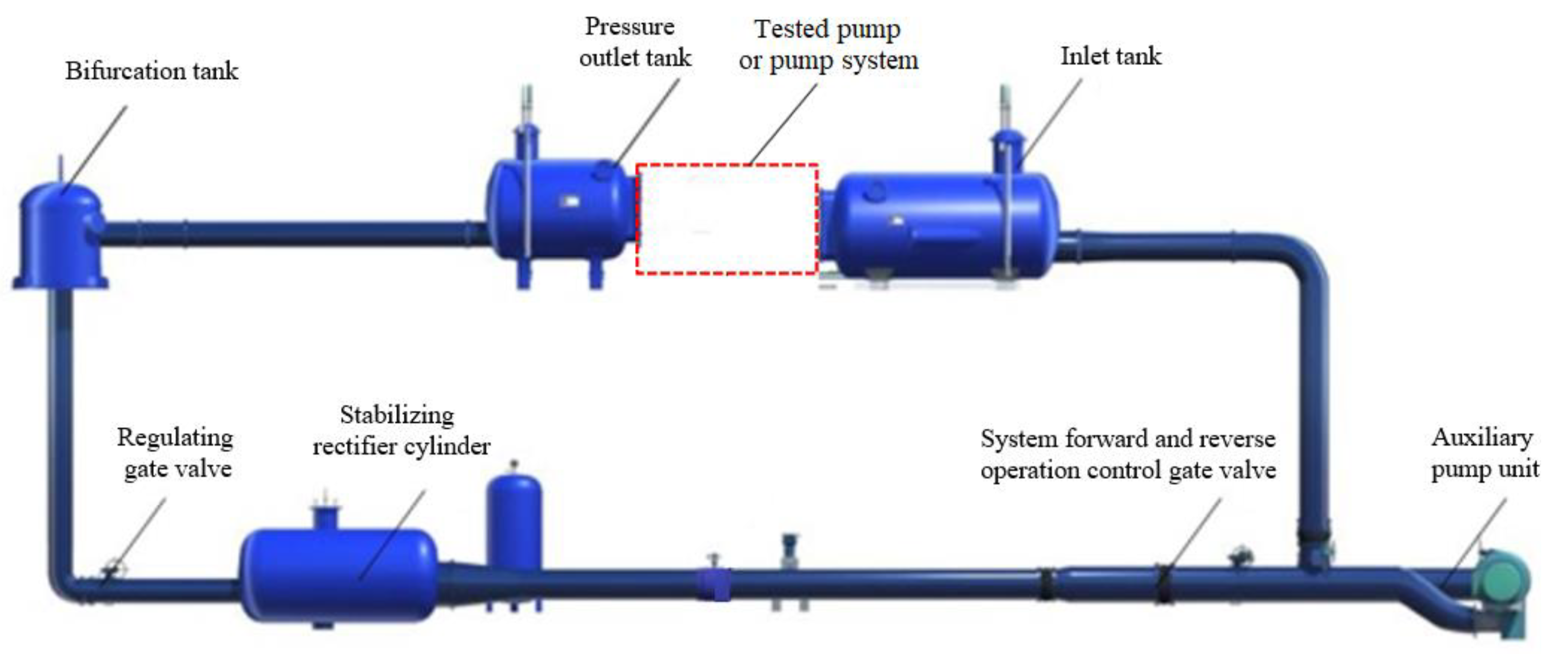
3.3. Experimental Platform and Experimental Model

The experimental tests in this paper were conducted on a high-precision hydraulic machinery test bench at the Key Laboratory of Hydraulic Power Engineering in Jiangsu Province. The test bench is a closed-cycle system with a comprehensive system uncertainty of ±0.39%. The test bench uses differential pressure transmitters to measure the head. The differential pressure transmitter’s model is EJA110A. The range is 0~200 kPa. The calibration accuracy is ± 0.1%. The flow is measured by using an electromagnetic flow meter. The electromagnetic flow meter model’s type comprises E-mag. The range is DN400 mm. The calibration accuracy is ± 0.20%. The torque is measured by the speed and torque sensor. The speed and torque sensor’s model is ZJ. The range is within 200 N-m. The calibration accuracy is ±0.15%. Figure 4 shows the schematic diagram of the high-precision hydro-mechanical test bench.
To support the numerical simulations in this paper, experimental tests of the pump model and experimental tests of the LAPS model need to be carried out. One of the experimental tests of the LAPS model includes the experimental test of energy characteristics and the experimental power-off runaway test. Figure 5 shows the physical field diagram of the experimental test of the LAPS model.

4. Model Validation

4.1. Steady-State Simulation Verification

In this section, the energy characteristics tests of the LAPS model are carried out on the experimental platform to verify the steady-state simulation results of the simulation model. The experimental and simulated energy characteristics of LAPS are provided in Figure 6. From Figure 6, it can be observed that the head and shaft power obtained from the experimental test are very close to those obtained from the simulation, and the maximum error under different flow conditions did not exceed 10%. A simulation error value within 10% is often acceptable. The error in energy characteristics is mainly a result of the roughness of the model used in the experiment, which is affected by processing, and there are often some errors. From the overall point of view, the variation trends observed in simulation results and experimental results are consistent. This shows that the simulation model built in this paper is more accurate, and the steady-state simulation based on the simulation model in this paper exhibits high accuracy.

4.2. Transient Simulation Verification

In this section, a power-off runaway test and a power-off runaway simulation were carried out for the LAPS model to validate the transient simulation results for the simulation model. The runaway speed of the pump after LAPS is powered off is provided in Figure 7. From Figure 7, it can be observed that after LAPS was powered off at different heads. The experimental measurements and simulations of the runaway speed are very close to each other. Moreover, the variation pattern exhibits very high consistency, with a maximum error of no more than 10%, indicating that the transient simulation of LAPS’s transition process based on the numerical strategy and simulation model of this paper is highly feasible and the accuracy of the simulation’s results can be guaranteed.

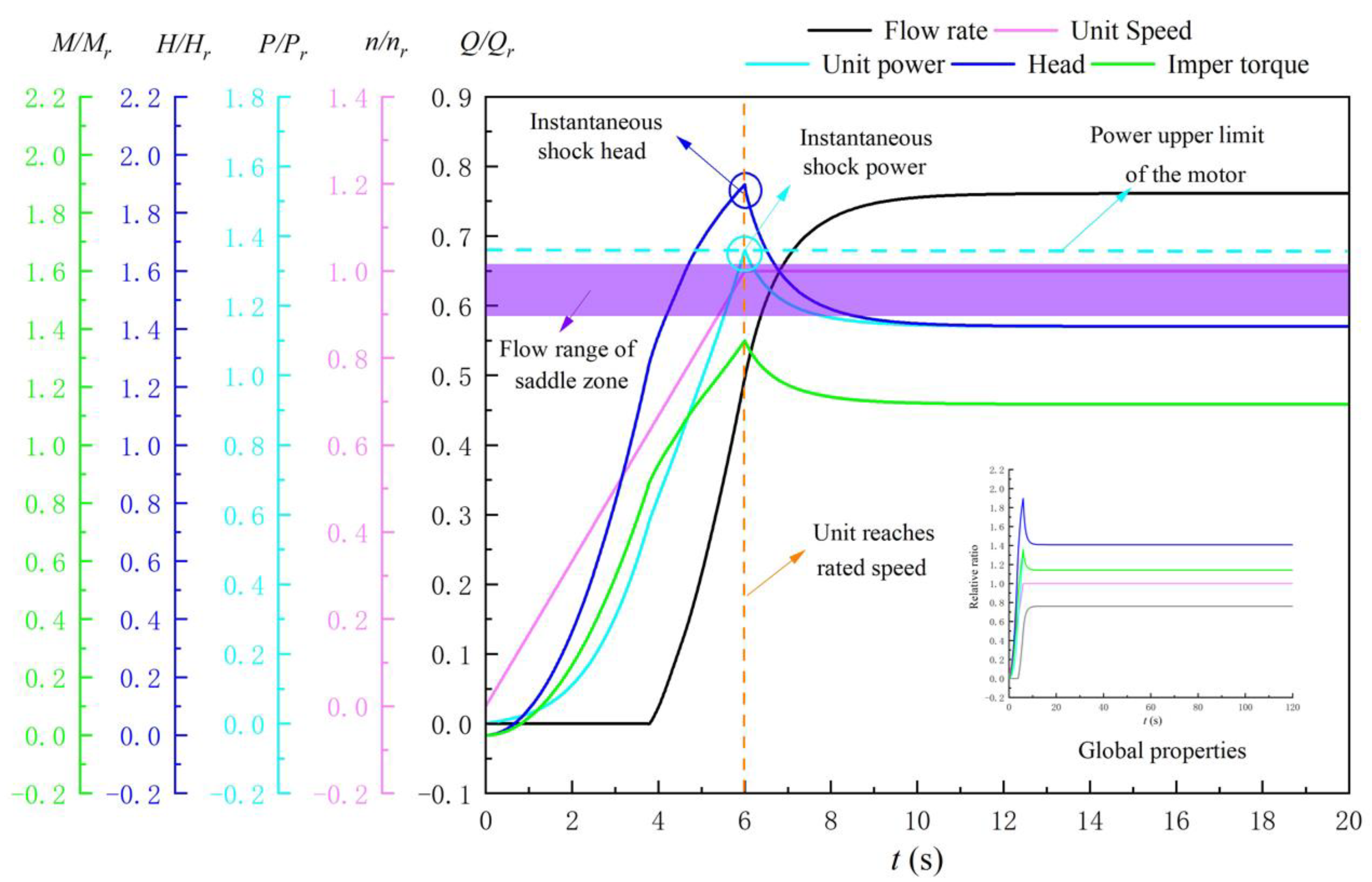
5. Results and Discussion

5.1. Gate Refusal Working Condition Equipped with OVHO

In order to investigate the applicability of OVHO to the problem of start-up failure due to gate refusal working conditions, numerical simulations of the start-up process under gate refusal working conditions were performed for the LAPS equipped with OVHO in this section. Five different elevations, including 5.55 m, 5.85 m, 6.15 m, 6.45 m, and 6.75 m OVHO, corresponding to 1.04, 1.09, 1.15, 1.21, and 1.27 times the maximum net head, respectively, were examined. The simulation model in this section includes an upstream reservoir; components 1, 2, 3, 4, and 5; a 60° bend; a downstream reservoir; a gate controller; a pump speed controller; and no FLVA (component 6) is set. The opening of the fast gate is always kept at zero during the simulation. It should be noted that the descriptions of OVHO elevations in this paper are all relative elevations.
According to the operation experience of LAPS’s field, when the pump system reaches the rated speed, the corresponding flow falls within the flow range of the saddle area, or the corresponding flow falls within the flow range of the saddle area when the pump system starts, which will lead an unstable LAPS start-up process that is affected by the saddle area. The pump’s performance test found that the flow in the saddle zone ranges from 7.5 m3/s (0.586 Qr) to 8.5 m3/s (0.664 Qr).
Figure 8 provides the variation pattern of the flow and head of LAPS equipped with OVHO under the gate refusal working condition. The purple area range in Figure 8 is the LAPS saddle zone’s flow range. The following conclusions can be drawn from Figure 8. First, the LAPS equipped with a 6.75 m elevation (1.27 Hm) OVHO under gate refusal working conditions may experience start-up instability due to falling within the saddle zone. The flow rate corresponding to the unit—when the start-up is completed and enters into stable operation—is 0.646 Qr, which falls within the flow rate range of the saddle zone. Second, the LAPS equipped with different OVHO elevations under gate refusal working conditions did not have any backflow during the start-up process. The timing of overflow at LAPS initiation varies for different elevations of OVHO, but it is very close. When equipped with a 5.55 m elevation OVHO. The time for overflow to occur at the OVHO is 3.850 s. Moreover, when equipped with a 6.75 m elevation (1.27 Hm) OVHO, the time for overflow to occur at the OVHO is 4.225 s.
The His and Pis of the LAPS equipped with OVHO for the gate refusal working condition are provided in Figure 9. The following conclusions can be drawn from Figure 9. First, under the gate refusal working condition, when the elevation of LAPS equipped with OVHO is higher than 5.55 m (1.04 Hm). The Pis during LAPS start-up will exceed the power limit of the motor, which will lead to motor overload and pump station start-up failure. The Pis of the LAPS equipped with a 5.85 m elevation (1.09 Hm) OVHO reached 1.377 Hr. Second, under the gate refusal working condition, His and Pis increase gradually as the elevation of the LAPS equipped with OVHO increases gradually. The His of LAPS equipped with 5.55 m (1.04 Hm) OVHO elevation is 1.876 Hr, and the Pis is 1.349. The His of the LAPS equipped with OVHO at 6.75 m elevation (1.27 Hm) is 2.100 Hr, and Pis is 1.467 Pr.
The start-up characteristic curve of the LAPS equipped with 6.15 m elevation (1.15 Hm) OVHO under gate refusal working conditions is provided in Figure 10. As observed in Figure 10, when the unit starts, the pump’s speed gradually increases. The key characteristic parameters, such as the head and shaft power, increase linearly, and water gradually fills the outlet channel of LAPS. As the gate refuses to open, when t = 4.050 s, the OVHO starts to overflow, and the rising trend of the head and power of LAPS becomes steep and slow. When t = 6 s, the unit reaches the rated speed. The head and power of LAPS reach the maximum value simultaneously at 1.988 Hr and 1.407 Pr, respectively. When the unit reaches the rated speed, LAPS gradually transitions to the regular operating condition, and the key characteristic parameters rapidly converge toward stable values within a few seconds. After stabilization, the flow rate of LAPS is 0.721 Qr. The head is 1.475 Hr. The power is 1.169 Pr, and the impeller torque is 1.169 Mr. It should be noted that the LAPS equipped with a 6.15 m height (1.15 Hm) OVHO has a Pis of 1.407 Pr, which exceeds the upper power limit of the motor and may result in a failed start or even motor burnout.

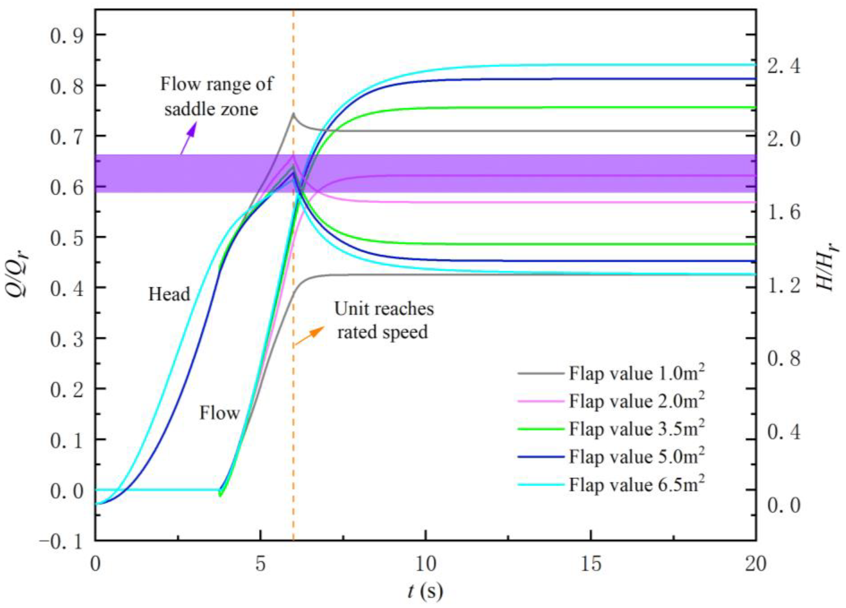
5.2. Gate Refusal Working Conditions Equipped with FLVA

To investigate the applicability of FLVA with respect to the problem of gate refusal working conditions leading to start-up failure, in this section, numerical simulations of the start-up process under gate refusal working conditions were performed for the LAPS equipped with FLVA. Five different sizes of the FLVA measuring 1.0 m2, 2.0 m2, 3.5 m2, 5.0 m2, and 6.5 m2 at 7.5%, 15.0%, 26.4%, 37.7%, and 49.1% of the fast gate area (Ag), respectively, were applied. The simulation model in this section includes the upstream reservoir; components 1, 2, 3, 5, and 6; a 60° bend; a downstream reservoir; a gate controller; a pump speed controller; and no OVHO (component 4). The opening of the fast gate is always kept at zero during the simulation.
Figure 11 provides the variation pattern of the flow and head of the LAPS equipped with FLVA under the gate refusal working condition. The purple area range in Figure 11 is the LAPS saddle zone’s flow range. The following conclusions can be drawn from Figure 11. First, the LAPS equipped with a 2.0 m2 (15% Ag) FLVA under gate refusal working conditions may experience starting instability during start-up due to falling into the saddle zone. The flow rate corresponding to the unit when the start-up is complete, and it enters steady operation is 0.622 Qr, which falls within the flow rate range of the saddle zone.
LAPS with 1.0 m2 (7.5% Ag) FLVA exhibits a flow rate of 0.387 Qr, and the LAPS with 6.5 m2 (49.1% Ag) FLVA has a flow rate of 0.548 Qr when the unit reaches the rated speed. None are within the flow range of the saddle zone. Second, the LAPS equipped with FLVA is free from backflows during the start-up process under the gate refusal working condition. During the start-up process of LAPS, the time for the FLVA of different sizes to flow out of FLVA after being opened by water impact is very similar.
The His and Pis of the LAPS equipped with FLVA under the gate refusal working condition are provided in Figure 12. The following conclusions can be drawn from Figure 12. First, under the gate refusal working condition, when LAPS is equipped with an FLVA with an area of less than 2.0 m2, Pis during LAPS start-up processes will exceed the upper power limit of the motor, resulting in motor overload and pump station start-up failure. The Pis of LAPS equipped with 2.0 m2 (15.0% Ag) of the FLVA reached 1.364 Pr. Second, His and Pis both decrease gradually as the area of the FLVA equipped with LAPS increases gradually under the gate refusal working condition. The LAPS with 1.0 m2 (7.5% Ag) FLVA has an His of 2.133 Hr and a Pis of 1.485 Pr. The LAPS with 6.5 m2 (49.1% Ag) FLVA has an His of 1.772 Hr and a Pis of 1.308 Pr. Third, when the FLVA area is greater than 2.0 m2 (15% Ag). The decreasing trend of the His of the pump’s system tends to level off, and Pis remains basically unchanged.
The start-up characteristic curve of LAPS equipped with 3.5 m2 (26.4%Ag) FLVA under gate refusal working conditions is provided in Figure 13. As observed in Figure 13, when the unit starts, the pump’s speed gradually increases. The key characteristic parameters, such as the head and shaft’s power, increase linearly, and the water gradually fills the outlet channel of LAPS. As the gate refuses to open, when t = 3.90 s, the FLVA starts to overflow. When t = 6 s, the unit reaches the rated speed, and the head and power of LAPS reach the maximum value simultaneously at 1.988 Hr and 1.407 Pr, respectively. When the unit reaches the rated speed, LAPS gradually transitions to the regular operating condition, and the key characteristic parameters rapidly converge toward stable values within a few seconds. After stabilization, the flow rate of LAPS is 0.756 Qr. The head is 1.418 Hr. The power is 1.144 Pr, and the impeller torque is 1.144 Mr. The LAPS equipped with a 3.5 m2 (26.4%Ag) FLVA has a Pis of 1.332 Pr, which is lower than the upper power limit of the motor and can avoid motor overload when LAPS starts.

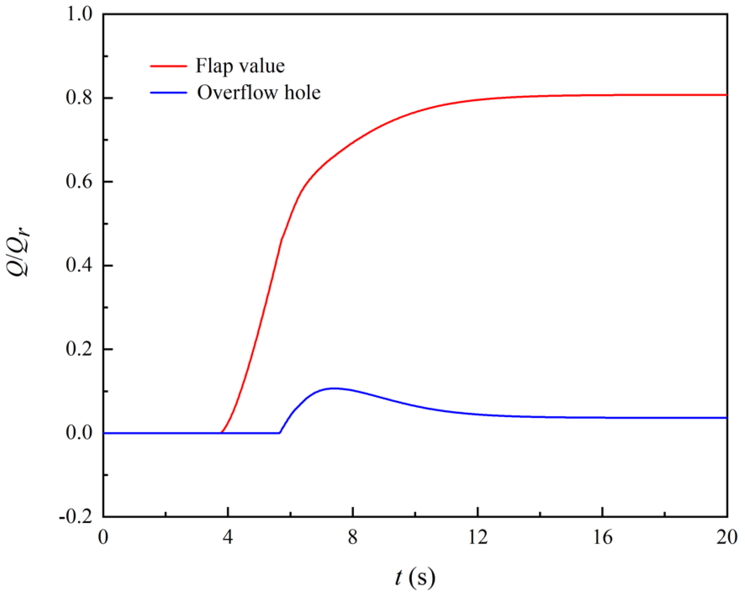
5.3. Gate Refusal Working Conditions with Both FLVA and OVHO

From Section 5.1 and Section 5.2, it was observed if the LAPS is equipped with a suitable FLVA or OVHO, both will provide good protection for the LAPS start-up process under gate refusal working conditions. This section is based on the premise that the installation of safety aids is not restricted, and an installation of 5.55 m OVHO (1.04 Hm) and 6.5 m2 (49.1% Ag) FLVA was selected. Numerical simulations of the start-up process under gate refusal working conditions for LAPS equipped with both OVHO and FLVA were performed. The simulation model in this section includes the upstream reservoir, elements 1, 2, 3, 4, 5, and 6, a 60° bend, a downstream reservoir, a gate controller, and a pump speed controller. The opening of the fast gate is always kept at zero during the simulation.
The starting characteristic curve of the LAPS equipped with OVHO (1.04 Hm) and FLVA (49.1% Ag) for the gate refusal working condition is provided in Figure 14. The flow at OVHO (1.04 Hm) and FLVA (49.1% Ag) are provided in Figure 15. The following conclusions can be drawn by combining Figure 14 and Figure 15. First, during the start-up of LAPS equipped with both OVHO and FLVA, FLVA plays the main protective role. When t = 3.80 s, the outflow at FLVA starts, and then the flow at FLVA gradually increases until it fully assumes the outflow task of LAPS. Second, OVHO plays a very weak protective role during the start-up of LAPS equipped with both OVHO and FLVA. When t = 5.675 s, the flow starts to exit OVHO. Subsequently, the flow at OVHO first increases and then decreases, with a maximum diversion flow of 0.106 Qr. When t = 15.975 s, OVHO stops working. Third, the LAPS equipped with both OVHO (1.04 Hm) and FLVA (49.1% Ag) is equivalent to LAPS that are only equipped with an FLVA (49.1% Ag) in terms of safety during start-up operations. The latter has an His of 1.783 Hr and a Pis of 1.30 Pr. The former has an His of 1.772 Hr and a Pis of 1.30 Pr. They decreased by 0.38% and 0%, respectively.

5.4. Gate Refusal Working Condition and Limited FLVA Area

As both FLVA and OVHO are equipped, the actual project requires a comprehensive consideration of structural safety, construction difficulties, and other factors, which often leads to limitations for FLVA or for the elevation of the OVHO. Therefore, when the size of an auxiliary safety facility is limited, it is often necessary to coordinate with another safety facility to ensure the safety of LAPS start-up processes. This section is based on the premise that FLVA area settings are limited. The numerical simulation of the start-up process under gate refusal working conditions is performed for LAPS equipped with a 1.0 m2 (7.5% Ag) FLVA and different elevations of OVHO. Auxiliary OVHO elevations include 5.55 m, 5.85 m, 6.15 m, 6.45 m, and 6.75 m, corresponding to 1.04, 1.09, 1.15, 1.21, and 1.27 times the maximum net head, respectively. The simulation model in this section includes the upstream reservoir; elements 1, 2, 3, 4, 5, and 6; a 60° bend; a downstream reservoir; a gate controller; and a pump speed controller. The opening of the fast gate is always kept at zero during the simulation.
The variation patterns of the flow and head of LAPS equipped with OVHO and a restricted FLVA under gate refusal working conditions are provided in Figure 16. The purple area range in Figure 16 is the LAPS saddle zone’s flow range. Figure 17 provides the Pis and His of the LAPS equipped with OVHO and a restricted FLVA for the gate refusal working condition. The following conclusions can be obtained by combining Figure 16 and Figure 17. First, the LAPS equipped with a 6.75 m elevation (1.27 Hm) OVHO under gate refusal working conditions may experience start-up instability during start-up processes due to falling into the saddle area. The flow rate corresponding to the unit when the start-up is completed and enters steady operation is 0.652 Qr, which falls within the flow rate range of the saddle area. Secondly, under the gate refusal working condition, as the elevation of the equipped auxiliary OVHO gradually increases, His and Pis also increase in an approximately linear manner. Third, under gate refusal working conditions, on the basis of the LAPS equipped with 1.0 m2 FLVA (49.1% Ag), further equipping OVHO below 5.85 m of elevation (1.09 Hm) can ensure the safety of the motor during starting operations. The LAPS equipped with a 5.85 m elevation OVHO (1.09 Hm) has an His of 1.897 Hr and a Pis of 1.359 Pr. The LAPS equipped with a 5.55 m OVHO (1.04 Hm) has an His of 1.852 Hr and a Pis of 1.337 Pr.
Figure 18 shows the variation in the outflow from the safety aid using restricted FLVA settings. The following conclusions can be drawn from Figure 18. First, under the gate refusal working condition, as the elevation of the equipped auxiliary OVHO gradually increases, the shunting effect of OVHO gradually decreases, and the shunting effect of FLVA gradually increases. When the auxiliary is equipped with a 5.55 m elevation (1.04 Hm) OVHO, the flow rate at FLVA after the start-up process is completed is 0.176 Qr, accounting for 22% of the system’s outflow. The flow at OVHO is 0.624 Qr, accounting for 78% of the system’s outflow. When the auxiliary is equipped with 6.75 m elevation (1.27 Hm) OVHO, the flow rate at FLVA after the start-up is completed is 0.292 Qr, which is 45% of the system’s outflow. The flow at OVHO is 0.360 Qr, which is 55% of the system’s outflow. Second, under the gate refusal, working conditions. As the height of the equipped auxiliary OVHO gradually increases, the time for the water to top off the FLVA’s outflow remains essentially the same. The time period for when water flows over OVHO’s outflow gradually becomes delayed. When equipped with 5.55 m of elevation (1.04 Hm), the time period for the water to diffuse through the OVHO is 4.40 s. When the auxiliary is equipped with 6.75 m elevation OVHO (1.27 Hm), the time period for the water to diffuse through the OVHO’s outflow is 5.325 s.
The start-up characteristic curves of the LAPS equipped with 5.85 m OVHO (1.09 Hm) and FLVA (7.5% Ag) for the gate refusal working condition are provided in Figure 19. According to Figure 19, when the unit reaches the rated speed, the head and power of LAPS also reach the maximum value simultaneously at 1.897 Hr and 1.359 Pr, respectively. Subsequently, LAPS gradually transitioned to conventional operating conditions, and the key characteristic parameters quickly stabilized within a few seconds. After stabilization, the flow rate of LAPS is 0.496 Qr. The head is 1.409 Hr. The power is 1.141 Pr, and the impeller torque is 1.141 Mr. The LAPS equipped with a 1.0 m2 area (7.5%Ag) FLVA has a Pis of 1.359 Pr, which is lower than the upper power limit of the motor exhibiting 1.360 Pr and may avoid motor overload when LAPS starts.

5.5. Gate Refusal Working Condition and Limited OVHO Height

Section 5.4 investigates the LAPS initiation process when the FLVA’s area is limited, and the auxiliary is equipped with OVHO. In this section, the numerical simulation of the start-up process under gate refusal working conditions is carried out for LAPS equipped with an OVHO that is 6.75 m in height (1.27 Hm) and FLVAs measuring different areas, with the premise that the OVHO’s height setting is restricted. The simulation model in this section includes the upstream reservoir; elements 1, 2, 3, 4, 5, and 6; a 60° bend; a downstream reservoir; a gate controller; and a pump speed controller. The opening of the fast gate is always kept at zero during the simulation.
Figure 20 provides the variation law of the flow and head of LAPS equipped with FLVA and restricted OVHO under gate refusal working conditions. The purple area range in Figure 20 is the LAPS saddle zone’s flow range. The Pis and His of the LAPS equipped with OVHO and restricted FLVA for the gate refusal working condition are provided in Figure 21. The following conclusions can be obtained by combining Figure 20 and Figure 21. First, under gate refusal working conditions, the LAPS with an auxiliary 1.0 m2 (7.5% Ag) FLVA may experience instability during start-up procedures because it falls within the saddle area. The flow rate corresponding to the unit—when the start-up operation is completed, and it enters steady operation—is 0.652 Qr, which falls within the flow rate range of the saddle area. Second, His and Pis gradually decrease with the increase in area with respect to the auxiliary FLVA that is equipped under the gate refusal working condition. Pis tends to stabilize when the equipped auxiliary FLVA area is greater than 2.0 m2 (15.0% Ag). The Pis of the LAPS with the equipped auxiliary 3.5 m2 (26.4% Ag) FLVA is 1.333 Pr. The Pis of the equipped auxiliary 6.5 m2 (49.1% Ag) FLVA is 1.305 Pr. Third, the gate refusal working condition, on the basis of being equipped with a 6.75 m elevation (1.27 Hm) OVHO and that is further equipped with more than 2.0 m2 (15.0% Ag) of FLVA, can ensure the safety of the motor during the starting process.
Figure 22 provides the outflow variations for different safety aids with restricted OVHO settings. The following conclusions can be drawn from Figure 22. First, under gate refusal working conditions, the protective role of OVHO in LAPS start-up operations discernibly weakened as the area of the equipped auxiliary FLVA gradually increased. Moreover, the FLVA dominated in its protective role. When the auxiliary was equipped with an FLVA with an area of 3.5 m2 (26.4% Ag) or more, the protection against LAPS initiation was fully covered by the FLVA. When the auxiliary was equipped with a 1.0 m2 (7.5% Ag) FLVA, the flow rate at the FLVA after the start-up operation was completed was 0.292 Qr, which is 45% of the system’s outflow. The flow at OVHO is 0.360 Qr, accounting for 55 % of the system’s flow. When the auxiliary was equipped with a 2.0 m2 (15.0% Ag) FLVA, the flow rate at the FLVA after the start-up operation was completed was 0.555 Qr, which is 82% of the system’s outflow. The flow at OVHO is 0.118 Qr, accounting for 18 % of the system’s flow. Secondly, under the gate refusal working condition, as the elevation of the equipped auxiliary OVHO gradually increased, the time period of water flowing out of the FLVA remained the same, and the time period of water flowing out of OVHO was gradually delayed. When the auxiliary was equipped with a 1.0 m2 (7.5% Ag) FLVA, the time period for the water to diffuse through the OVHO’s outflow was 5.325 s. When the auxiliary was equipped with a 2.0 m2 (15.0% Ag) FLVA, the time for the water to diffuse through the OVHO’s outflow was 6.225 s.
The starting characteristic curves of the LAPS equipped with FLVA (26.4% Ag) and OVHO (1.27 Hm) for the gate refusal working condition are provided in Figure 23. According to Figure 23, it can be seen that when the unit reaches its rated speed. The head and power of LAPS also reached their maximum values simultaneously at 1.905 and 1.364, respectively. Subsequently, the LAPS gradually transitions to regular operating conditions, and each key characteristic parameter rapidly converges to a stable value within a few seconds. After stabilization, the flow rate of LAPS is 0.673 Qr. The head is 1.557 Hr. The power is 1.204 Pr, and the impeller torque is 1.204 Mr. The LAPS equipped with a 2.0 m2 (15.0% Ag) FLVA has a Pis of 1.364 Pr, which is higher than the motor power limit of 1.360 Pr and may avoid motor overload when LAPS starts.

5.6. Analysis of Different Safety Auxiliary Facilities to Prevent Starting Failure

In order to comprehensively assess the effectiveness of different safety aids in preventing LAPS start-up failures under the gate refusal working condition, this section analyzes the start-up failure data of LAPSs equipped with different safety aids. The LAPS start-up risk under gate refusal working conditions is also compared based on the key indicators for predicting start-up failure. The key reasons for the failure of LAPS start-ups under gate refusal working conditions have been explained in a previous section. One is the flow range falling into the saddle area during the start-up process, and the other is that Pis is too large and cannot cause an overload in the motor. Therefore, the key indicators analyzed in this section include the flow rate, Qus, corresponding to the LAPS when the unit reaches synchronous speeds; the flow rate, Qsc, corresponding to the LAPS when the start-up is completed, and Pis during start-up operations.
The key indicators of the LAPS start-up process under gate refusal working conditions are provided in Figure 24. The following conclusions can be drawn from Figure 24. First, the gate refusal working condition will cause a failure when LAPS starts at the saddle area if the safety aids are not properly sized. When only one safety auxiliary facility is equipped, setting an FLVA of 2.0 m2 or 6.75 m elevation OVHO will cause the corresponding flow in LAPS to fall within the flow range of the saddle area when it reaches a stable operating state.
Second, the gate refusal working condition will cause the LAPS motor to overload and fail to start if the safety aids are not properly sized. When an FLVA is selected for safety assistance, a 1.0~2.0 m2 (7.5% Ag~15% Ag) FLVA will not be able to avoid motor overload during LAPS start-up operations. When choosing to equip OVHO for safety assistance, an OVHO of 5.85~6.75 m (1.09 Hm~1.27 Hm) will result in motor overload during LAPS start-up operations.
Third, when the size of a certain safety auxiliary facility is limited, other safety auxiliary facilities can further be equipped to avoid the failure of LAPS start-up operations under the condition of gate rejection. When the size of the FLVA is severely limited, OVHOs with elevations below 1.09 Hm guarantee the safety of the LAPS start-up process. When OVHO’s size is severely limited, an FLVA that is larger than 2.0 m2 (15% Ag) is sufficient for ensuring the safety of the LAPS’s start-up process.

6. Conclusions

This paper presents a numerical simulation of the start-up process of LAPS equipped with safety aids under gate refusal working conditions. The applicability of different types of safety auxiliary facilities in dealing with the failure of LAPS start-ups caused by gate refusal working conditions was discussed. The effect of the size of the safety aids on the LAPS’s start-up characteristics under gate refusal working conditions was analyzed. A comprehensive comparison of the effects of different safety aids on LAPS’s start-up failures was also conducted. The main conclusions drawn are as follows:
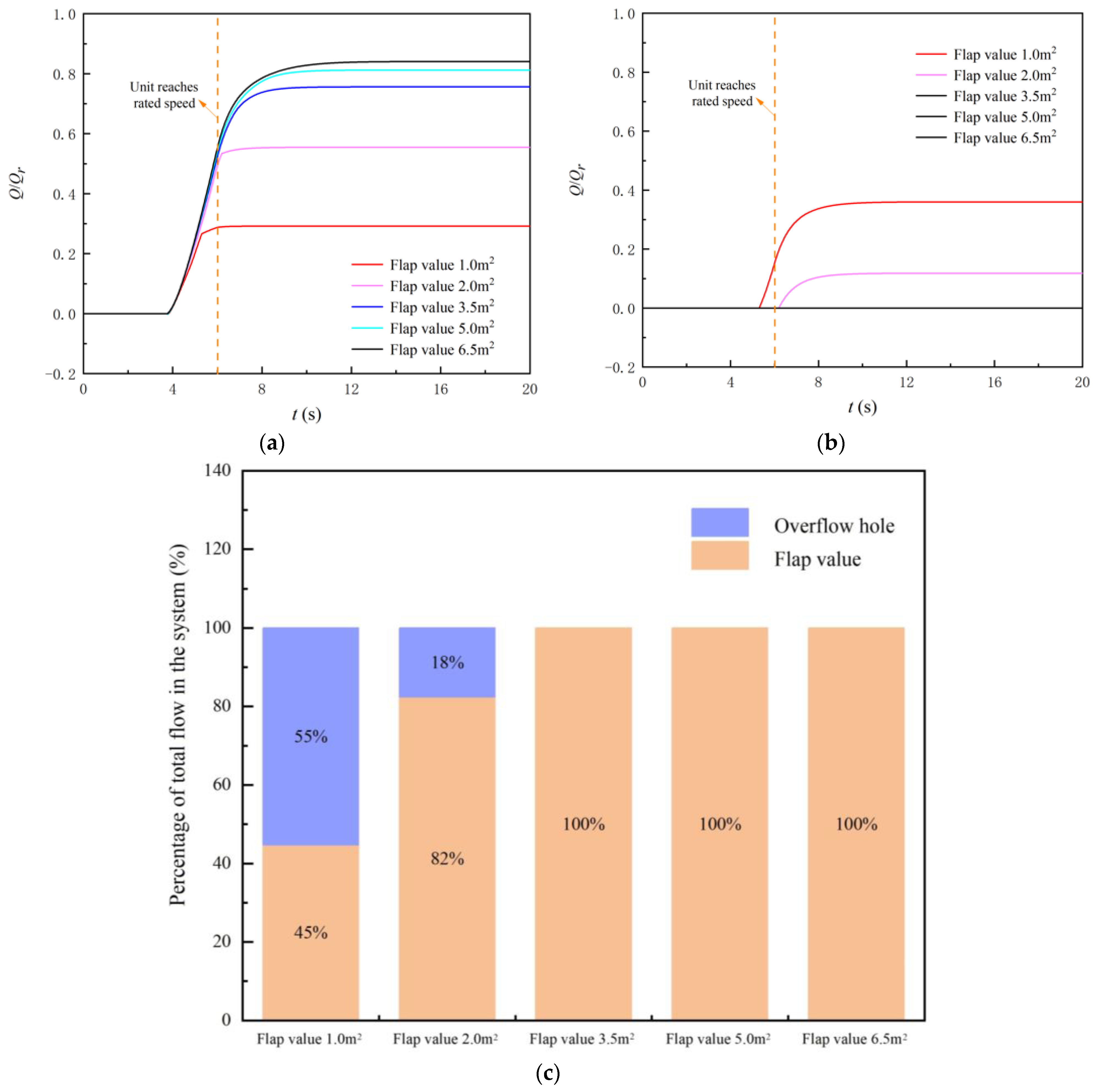
  • Auxiliary OVHO or FLVA equipment can help LAPS in reducing risks that may occur during start-up failure to some extent under gate refusal working conditions. The LAPSs equipped with FLVA or OVHO are basically free from backflow during start-up operations. Moreover, the time periods with respect to FLVA or OVHO assist LAPS’s outflow and are minimally influenced by FLVA’s area or OVHO’s elevation;
  • Under the gate refusal working condition, when Pis during the start-up process is reduced by setting up safety auxiliary facilities, LAPS falls into the saddle area after start-up operations are completed, and the start-up is unstable. When equipped with only one type of safety aid, setting an FLVA measuring 2.0 m2 or 6.75-meter elevation OVHO will cause the flow corresponding to the LAPS’s transition to behave in a steady-state manner and to fall within the flow range of the saddle’s zone;
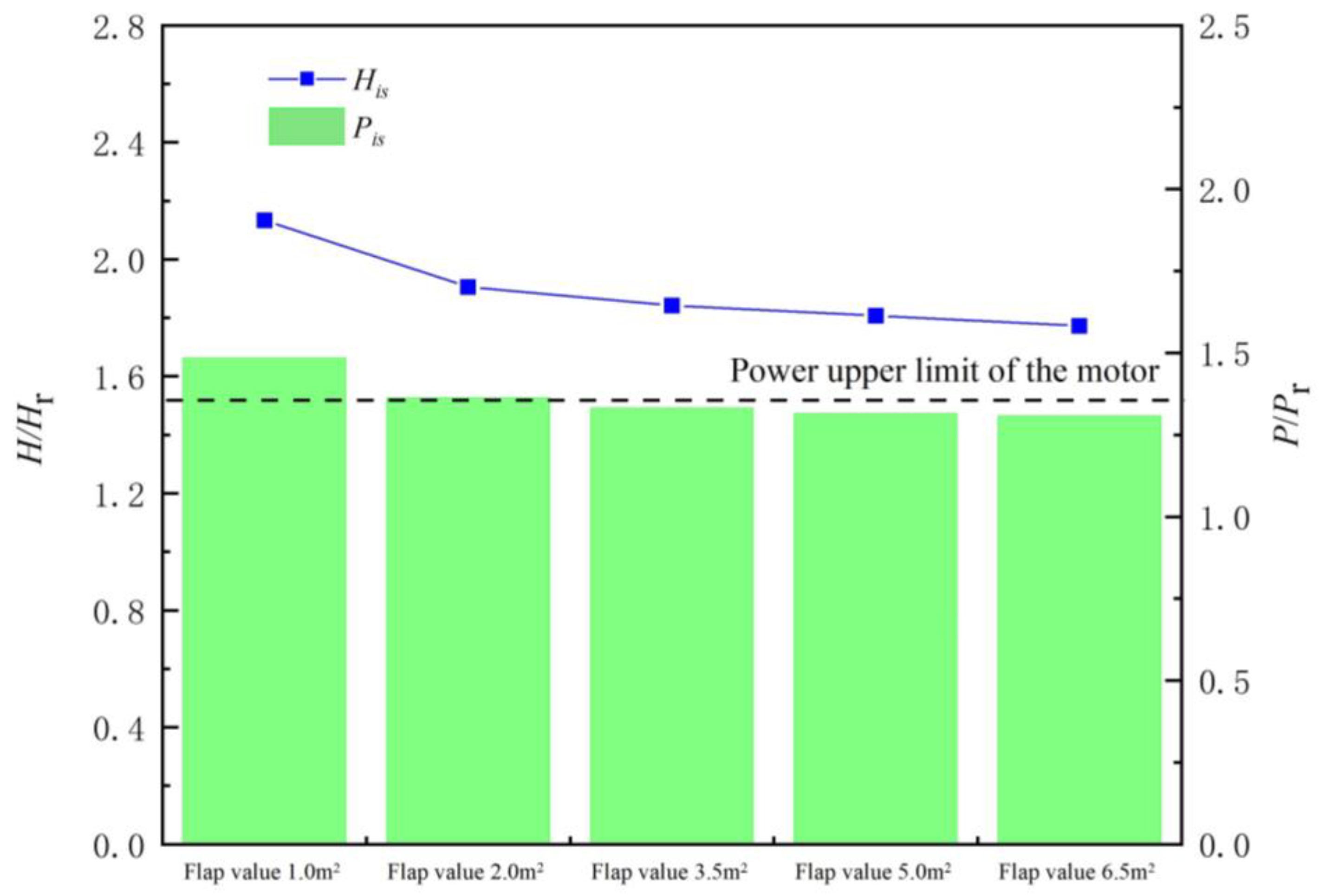
  • The FLVA will play the main protective role during the start-up operation of the LAPS if the LAPS is equipped with both an OVHO and FLVA of unrestricted size under the gate refusal condition. The LAPS equipped with OVHO (1.27 Hm) and FLVA (49.1% Ag) and the LAPS equipped with FLVA (49.1% Ag) both exhibit comparable safe start-up operations. The latter has an His of 1.783 Hr and a Pis of 1.30 Pr. The former has an instantaneous shock head of 1.772 Hr and a Pis of 1.30 Pr, which exhibit decreases of 0.38% and 0%, respectively;
  • When the size of a safety aid is limited, other safety aids can be further equipped to avoid the failure of LAPS activations under gate refusal working conditions. When the FLVA’s size is severely limited, possessing an OVHO below 1.09 Hm in elevation will ensure the safety of the LAPS’s start-up process. When the OVHO’s size is severely limited, an FLVA with more than 2.0 m2 (15% Ag) will ensure the safety of the LAPS’s start-up process.

Author Contributions

X.Z.: Conceptualization, Software, Methodology, Writing—Original, draft preparation, and Supervision, C.Y.: Model experiment, Data curation, and Visualization, X.S.: Data curation, and Visualization, F.T.: Writing-Reviewing, Supervision, and Funding acquisition, C.H.: Model experiment and Data curation, F.Y.: Model experiment and Visualization, L.S.: Funding acquisition. All authors have read and agreed to the published version of the manuscript.

Funding

This research work was funded by the National Natural Science Foundation of China (funding number: 51376155), the National Natural Science Foundation of China (funding number: 52209116), the Scientific and Technological Research and Development Program of South-to North Water Transfer in Jiangsu Province (funding number: JSNSBD202201), and the Jiangsu Water Conservancy Science and Technology Project (funding number: 2021012).

Informed Consent Statement

Informed consent was obtained from all subjects involved in the study.

Data Availability Statement

Data available on request due to restrictions, e.g., privacy or ethics. The data presented in this study are available on request from the corresponding author.

Acknowledgments

A project funded by the Priority Academic Program Development (PAPD) of Jiangsu Higher Education Institutions Support for the construction and assembly of the facility was also provided by the Hydrodynamic Engineering Laboratory of Jiangsu Province.

Conflicts of Interest

The authors declare no conflict of interest.

Nomenclature

QrThe design flow (m3/s)
HrThe design net head (m)
HmThe maximum net head (m)
DThe impeller diameter (m)
nrThe rated speed (r/min)
JiThe inertia moment of the LAPS (kg·m2)
JmThe motor’s moment of inertia (m3/s)
PMThe motor’s maximum power (kW)
AgThe fast gate area (m2)
gLocal acceleration of gravity (m/s2)
HHead (m)
nRated speed (r/min)
tTime (s)
ρThe density of flow (kg/m3)
PrThe motor design power (kW)
MrThe design impeller torque
ηexpExperimental Efficiency (%)
ηsimSimulated Efficiency (%)
PisInstantaneous shock power (kW)
HisInstantaneous shock head (m)
HexpExperimental head (m)
HsimSimulated head (m)
QusUnit synchronous speed flow (m3/s)
QscUnit start-up completion flow (m3/s)
Abbreviations
CFDComputational fluid dynamics
LAPSLarge axial flow pump station system
FLVAFlap value
OVHOOverflow hole

References

  1. Song, X.; Chao, L.; Wang, Z. Prediction on the pressure pulsation induced by the free surface vortex based on experimental investigation and Biot-Savart Law. Ocean Eng. 2022, 250, 110934. [Google Scholar] [CrossRef]
  2. Yang, F.; Li, Z.; Yuan, Y.; Lin, Z.; Zhou, G.; Ji, Q. Study on vortex flow and pressure fluctuation in dustpan-shaped conduit of a low head axial-flow pump as turbine. Renew. Energy 2022, 196, 856–869. [Google Scholar] [CrossRef]
  3. Zhang, W.; Chen, F.; Tang, F.; Shi, L.; Liu, H.; Wang, L. An analysis of the hydraulic characteristics of different impel-lers in axial-flow pump devices. China Rural. Water Hydropower 2022, 8, 132–139. [Google Scholar]
  4. Zhang, X.; Tang, F. Investigation on hydrodynamic characteristics of coastal axial flow pump system model under full working condition of forward rotation based on experiment and CFD method. Ocean Eng. 2022, 253, 111286. [Google Scholar] [CrossRef]
  5. Zhang, X.; Tang, F. Investigation of the hydrodynamic characteristics of an axial flow pump system under special utilization conditions. Sci. Rep. 2022, 5, 5159. [Google Scholar] [CrossRef]
  6. Xu, Z.; Zheng, Y.; Kan, K.; Huang, J. Runaway characteristics of bidirectional horizontal axial flow pump with super low head based on entropy production theory. Trans. Chin. Soc. Agric. Eng. 2021, 37, 49–57. [Google Scholar]
  7. Zhang, Y.-L.; Ji, Y.-Y.; Zhao, Y.-J. Deep analysis of the transient behavior of centrifugal pumps during startup and shutdown. Meas. Control. 2022, 55, 155–163. [Google Scholar] [CrossRef]
  8. Walseth, E.C.; Nielsen, T.K.; Svingen, B. Measuring the Dynamic Characteristics of a Low Specific Speed Pump—Turbine Model. Energies 2016, 9, 199. [Google Scholar] [CrossRef] [Green Version]
  9. Wan, W.; Huang, W. Investigation of Fluid Transients in Centrifugal PumpIntegrated System with MultiChannel Pressure Vessel. J. Press. Technol. 2013, 135, 61301. [Google Scholar] [CrossRef]
  10. Chen, S.; Jiang, H.; Zhou, Z.; He, Z.; Yan, D. Study on start-up transient process simulation of large scale tubular pumping stations. J. Yangzhou Univ. (Nat. Sci. Ed.) 2009, 12, 74–78. [Google Scholar]
  11. Gu, M.X. Influence of Pump Characteristics on Water Hammer during Long-Distance Pressurized Water Supply Project; North China University of Water Resources and Hydropower: Zhengzhou, China, 2022. [Google Scholar]
  12. Zhang, L.; Zhang, J.; Yu, X.; Lv, J.; Zhang, X. Transient Simulation for a Pumped Storage Power Plant Considering Pressure Pulsation Based on Field Test. Energies 2019, 12, 2498. [Google Scholar] [CrossRef] [Green Version]
  13. Xiuli, M.; Giorgio, P.; Yuan, Z. Francis-Type Reversible Turbine Field Investigation During Fast Closure of Wicket Gates. J. Fluids Eng. Trans. ASME 2018, 140, 061103. [Google Scholar] [CrossRef]
  14. Zhang, X.X.; Cheng, Y.G.; Yang, J.D.; Xia, L.S.; Lai, X. Simulation of the load rejectiontransient process of a francis turbine by using a 1-D-3-D coupling approach. J. Hydrodyn. 2014, 5, 51–60. [Google Scholar]
  15. Li, Q.; Ma, X.; Wu, P.; Yang, S.; Huang, B.; Wu, D. Study on the Transient Characteristics of the Centrifugal Pump during the Startup Period with Assisted Valve. Processes 2020, 8, 1241. [Google Scholar] [CrossRef]
  16. Yun, L.; Bin, L.; Jie, F.; Rongsheng, Z.; Qiang, F. Research on the Transient Hydraulic Characteristics of Multistage Centrifugal Pump During Start-Up Process. Front. Energy Res. 2020, 8, 76. [Google Scholar] [CrossRef]
  17. Sun, K.; Li, Y.; Zhao, J.; Zhang, L. Transient starting performance analysis of vertical axis tidal turbine. J. Huazhong Univ. Sci. Tech. (Nat. Sci. Ed.) 2017, 45, 51–56. [Google Scholar]
  18. Zhang, Y.-L.; Zhu, Z.-C.; Li, W.-G. Experiments on transient performance of a low specific speed centrifugal pump with open impeller. Proc. Inst. Mech. Eng. Part A J. Power Energy 2016, 230, 648–659. [Google Scholar] [CrossRef]
  19. Zhang, Y.; Zhu, Z.; Jin, Y.; Cui, B.; Li, Y.; Dou, H. Experimental study on a cen-trifugal pump with an open impeller during startup period. Therm. Sci. 2013, 22, 1–6. [Google Scholar] [CrossRef]
  20. Zhang, Y.-L.; Zhu, Z.-C.; Li, W.-G.; Xiao, J.-J. Effects of viscosity on transient behavior of a low specific speed centrifugal pump in starting and stopping periods. Int. J. Fluid Mech. Res. 2018, 45, 113–125. [Google Scholar] [CrossRef]
  21. Batista, N.C.; Melicio, R.; Matias JC, O.; Catalão, J.P.S. New bladeprofile for Darrieus wind turbines capable to self-start. In Proceedings of the IET Conference on Renewable Power Generation, Edinburgh, UK, 6–8 September 2011; pp. 1–5. [Google Scholar]
  22. Singh, M.A.; Biswas, A.; Misra, R.D. Investigation of self-starting and high rotor solidity on the performance of a three S1210 blade H-type Darrieus rotor. Renew. Energy 2015, 76, 381–387. [Google Scholar] [CrossRef]
  23. He, H.Y.; Sun, K.; Ma, Y.; Zhang, L. Self-starting performance numerical analysis of fixed-pitch verticalaxis hydro-turbine. Appl. Mech. Mater. 2014, 535, 102–105. [Google Scholar] [CrossRef]
  24. Shi, W.; Gong, R.; Tang, G.; Chen, S. Analysis on Start-up Transition of Diving Tubular Pumping Station Based on Matlab/Simulink Simulation. J. Irrig. Drain. 2016, 35, 97–102. [Google Scholar]
  25. Ge, Q.; Chen, S.; Wang, G.; Wang, L.; Yan, D. The Simulation During Start-up Transition of Bulb Type Tubular Pumping Station. Proc. CSEE 2006, 5, 159–163. [Google Scholar]
  26. Fu, S.; Zheng, Y.; Kan, K.; Chen, H.; Han, X.; Liang, X.; Liu, H.; Tian, X. Numerical simulation and experimental study of transient characteristics in an axial flow pump during start-up. Renew. Energy 2019, 146, 1879–1887. [Google Scholar] [CrossRef]
  27. Zhang, X.; Tang, F.; Liu, C.; Shi, L.; Liu, H.; Sun, Z.; Hu, W. Numerical Simulation of Transient Characteristics of Start-Up Transition Process of Large Vertical Siphon Axial Flow Pump Station. Front. Energy Res. 2021, 9, 706975. [Google Scholar] [CrossRef]
  28. Zhou, D.; Chen, H.; Zhang, L. Investigation of Pumped Storage Hydropower Power-Off T ransient Process Using 3D Numerical Simulation Based on SP-VOF Hybrid Model. Energies 2018, 11, 1020. [Google Scholar] [CrossRef] [Green Version]
  29. Zhou, D.; Chen, Y.; Chen, H.; Chen, S.; Yang, C. Study of Hydraulic Disturbances from Single-Unit Load Rejection in a Pumped-Storage Hydropower Station with a Shared Water Delivery System. IEEE Access 2019, 7, 153382–153390. [Google Scholar] [CrossRef]
  30. Menéndez, J.; Fernández-Oro, J.M.; Galdo, M.; Loredo, J. Transient Simulation of Underground Pumped Storage Hydropower Plants Operating in Pumping Mode. Energies 2020, 13, 1781. [Google Scholar] [CrossRef]
Figure 1. Schematic diagram of LAPS.
Jmse 11 00220 g001
Figure 2. Flowchart of the start-up process’s simulation strategy.
Jmse 11 00220 g002
Figure 3. Schematic diagram of the LAPS simulation model.
Jmse 11 00220 g003
Figure 4. Schematic diagram of the high-precision hydro-mechanical test bench.
Jmse 11 00220 g004
Figure 5. Experimental testing of the LAPS model.
Jmse 11 00220 g005
Figure 6. Energy characteristics of LAPS.
Jmse 11 00220 g006
Figure 7. Runaway speed of pumps after being powered off.
Jmse 11 00220 g007
Figure 8. Variation pattern of flow and head of LAPS equipped with OVHO under gate refusal working condition.
Jmse 11 00220 g008
Figure 9. His and Pis of LAPS with OVHO under gate refusal working conditions.
Jmse 11 00220 g009
Figure 10. Start-up characteristic curve of LAPS equipped with 6.15 m OVHO elevation under gate refusal working conditions.
Jmse 11 00220 g010
Figure 11. Variation pattern of the flow and head of LAPS equipped with FLVA under gate refusal working conditions.
Jmse 11 00220 g011
Figure 12. His and Pis of LAPS with FLVA under gate refusal working conditions.
Jmse 11 00220 g012
Figure 13. The start-up characteristic curve of LAPS equipped with 3.5 m2 (26.4%Ag) FLVA under gate refusal working conditions.
Jmse 11 00220 g013
Figure 14. Start-up characteristics curve of LAPS equipped with OVHO (1.04 Hm) and FLVA (49.1% Ag) under gate refusal working conditions.
Jmse 11 00220 g014
Figure 15. Flow at OVHO (1.04 Hm) and FLVA (49.1% Ag).
Jmse 11 00220 g015
Figure 16. Variation patterns in the flow and head of LAPS equipped with OVHO and restricted FLVA under gate refusal working conditions.
Jmse 11 00220 g016
Figure 17. His and Pis of LAPS with OVHO and restricted FLVA under gate refusal working operations.
Jmse 11 00220 g017
Figure 18. Variation in outflow from safety auxiliary facilities in the case of restricted FLVA settings. (a) FLVA. (b) OVHO. (c) Flow at FLVA and OVHO after start-up is complete.
Jmse 11 00220 g018
Figure 19. Start-up characteristic curves of LAPS equipped with OVHO (1.15 Hm) and FLVA (7.5% Ag) under gate refusal working conditions.
Jmse 11 00220 g019
Figure 20. Variation patterns of the flow and head of the LAPS equipped with FLVA and restricted OVHO under gate refusal working conditions.
Jmse 11 00220 g020
Figure 21. His and Pis of LAPS with FLVA and restricted OVHO under gate refusal working conditions.
Jmse 11 00220 g021
Figure 22. Variations in the outflow of safety auxiliary facilities in the case of restricted OVHO settings. (a) FLVA. (b) OVH. (c) Flow at FLVA and OVHO after completing start-up operations.
Jmse 11 00220 g022
Figure 23. Start-up characteristics curve of LAPS equipped with FLVA (15.0% Ag) and OVHO (1.27 Hm) under gate refusal working conditions.
Jmse 11 00220 g023
Figure 24. The key indicators of the LAPS start-up process under gate refusal working conditions. (a) Flow rate corresponds to LAPS when the unit reaches synchronous speeds. (b) Flow rate corresponding to LAPS at the completion of the unit’s start-up operations. (c) The instantaneous shock power during starting operations.
Jmse 11 00220 g024aJmse 11 00220 g024b
Table 1. The detailed dimensional parameters of OVHO and FLVA.
Area (m2)Mass (kg)Volume (m3)Moment of Inertia (kg∙m2)
1.03910.050124
2.07830.100498
3.513700.1751528
5.019580.2503118
6.525460.3255270
(a) FLVA
Elevation (m)Diameter (m)
5.551.5
5.851.5
6.151.5
6.451.5
6.751.5
(b) OVHO
Disclaimer/Publisher’s Note: The statements, opinions and data contained in all publications are solely those of the individual author(s) and contributor(s) and not of MDPI and/or the editor(s). MDPI and/or the editor(s) disclaim responsibility for any injury to people or property resulting from any ideas, methods, instructions or products referred to in the content.

