1. Introduction
Energy demand drove the industrial revolution in the 1800s, and it may drive another new round of industrial revolution in the 21st century [
1]. The ocean has abundant resources (e.g., minerals, renewable energy, genes, space, etc.), which are essential for human beings to achieve sustainable development [
2]. However, we have just explored less than 20% of the ocean, and only 5% in detail [
3,
4]. Although submersibles are the main working force for the research fleet, various deep-sea equipment deployed in the oil and gas (O&G) industry, offshore renewable energy (ORE), and undersea observatories are also fundamental to the effective exploration and utilization of the ocean world and marine resources.
Underwater wet-mateable connectors can be mated and de-mated under the sea, they have been extensively used in the above fields to reduce the cost and the time of installation, maintenance and reconfiguration [
5]. The O&G industry is the biggest consumer of wet-mateable connectors. With the increase in the depth of exploitation, wet-mateable electrical connectors that can be used in a harsh environment with high ocean pressure and submarine seismic risks are the main demand. As is experienced in the O&G exploration and production, most of the needed wet-mateable connectors with high voltage rates (less than 12 kV) should be operated at depths of up to 3000 m [
6]. ORE farms also need a large number of wet-mateable electrical connectors. With the development of technologies of offshore wind energy, tidal stream, and ocean current energy, the requirement for wet-mateable connectors with high power is also increasing [
7,
8]. In this field, the voltage rate of the required wet-mateable connectors ranges from 1 kV to 33 kV, while their depth rate is only up to 100 m [
6,
8]. The application of wet-mateable connectors in ORE farms has the advantage of allowing the transformer to be lifted out of the water with no need to lift the long and heavy cable [
9]. Another important application field of wet-mateable connectors is undersea observatories, for example, the Astronomy with a Neutrino Telescope and Abyss environmental RESearch (ANTARES) project [
10] and the next-generation neutrino telescopes KM3NeT [
11].
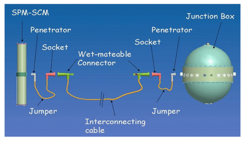
Figure 1 presents a schematic of the complete link between the string power module/string control module (SPM/SCM) and the junction box in ANTARES. Whereas the mounting of the jumpers is performed on shore, the completion of the wet-mate connection can be realized by a remotely operated vehicle (ROV) [
10]. So, wet-mateable connectors can provide an effective solution to the expansion and networking of undersea observatories [
3].
However, only a few developed countries can produce wet-mateable connectors worldwide. The key technologies are mostly confidential and protected by patents, so there are few published papers on this topic, which makes wet-mateable connectors become one of the bottleneck techniques in China [
3,
5]. Conceivably, the market price of wet-mateable connectors is very expensive. For example, the cost of a wet-mateable hybrid connector rated at 11 kV is expected to be in the range of £250 k/unit [
8], and even low-spec products may cost as much as £20 k/unit [
6]. Today, the top manufacturers of wet-mateable connectors include SEACON, MacArtney Group, Teledyne ODI, Siemens Energy, and so on. Each vendor has its own unique technology [
3,
7,
8].
In the past few years, the authors’ group has made some efforts in developing wet-mateable connectors. In 2021, Song and Cui [
3] gave a very detailed overview of wet-mateable connectors and proposed the concept of functional units to present a better understanding of the key technologies involving electrical/optical connection, pressure-balanced oil-filled (PBOF), penetrable self-sealing, automatic interlocking/docking (AID) and so on. Readers can refer to the literature [
3] for details. Among these key technologies, PBOF is the most essential for wet-mateable connectors, which can eliminate the differential pressure of connectors, making the wet-mate possible [
3,
5,
7,
12]. In 2022, Song et al. [
5] presented a very detailed investigation of PBOF technology and developed the core component used in wet-mateable connectors: a rubber-made resilient bladder [
5]. Compared to commercial off-the-shelf (COTS) products, this resilient bladder has a simple structure and lower cost, and it is more suitable for mass production. The results of the tests verified that the depth rate of the new bladder is greater than 6500 m. In the next step, the authors’ group aims to develop a wet-mateable electrical connector. The simulation technique involving a coupled multi-field problem is a proven way to save the cost and the time of research and development (R&D) [
13]. The finite element method (FEM) can be easily adapted to constitutive equations of different physical fields [
14]. So, finite element analysis (FEA) will play a very important role in this work.
In the future, the next-generation submersible will be more inspired by fish in nature. Compared with traditional submersibles, bio-inspired fish robots have the advantages of high efficiency, high maneuverability, low noise, and so on [
15,
16]. Meanwhile, the next-generation submersible will have more functions, such as underwater charging. If submersibles land on an underwater docking station, the power transfer can be achieved by using wet-mateable connectors [
17,
18]. Foreseeably, wet-mateable connectors must have a bright application prospect.
In this paper, the authors proposed an underwater wet-mateable electrical connector with dual-bladder PBOF technology. First, the generalized differential pressure equations of dual-bladder PBOF technology are derived. Second, a procedure of coupled multi-field simulation for wet-mateable electrical connectors is proposed. Then, a series of FEA is conducted, including thermal-electric coupling analysis, static structural analysis, and dynamic analysis. Finally, a prototype of the proposed connector is developed successfully, and its electrical performance is verified by a series of tests. The technical level of this prototype has reached the leading position in China. This paper might be the first discloser on wet-mateable connectors in the aspects of design, theory, simulation, and testing, which might be helpful to many ocean scientists in developing countries who are technically blocked or could not afford the high cost.
2. Design and Theory
2.1. Overall Design
The main specifications of the proposed wet-mateable electrical connector are listed in
Table 1. Considering the current demands in the O&G industry and undersea observatories in China, the operating depth of wet-mateable connectors will not exceed 3000 m in the next five years. Other specifications mainly refer to some first-class COTS products, such as SECAON HydraElectric, Nautilus
TM WM1.7-30, and Siemens DigiTRON.
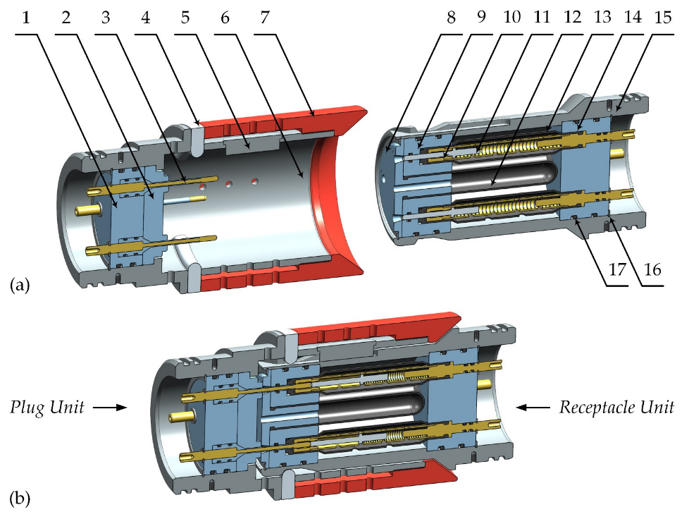
Figure 2 presents a schematic of the proposed connector which consists of two parts: the plug unit and the receptacle unit. The dual-bladder PBOF technology is introduced to improve reliability, and its core components are two kinds of resilient bladder (parts 12 and 13). The shuttle pin design is used in electric connections to achieve penetrable self-sealing, and its core component is a moveable stopper (part 11) and the contact pin with an insulating layer (part 3). The proposed connector also has the AID technology which can facilitate ROVs to operate under the sea, and its core component is a latching member (part 4). Compared to available products, the proposed connector is a smaller-sized one, whose maximum radial dimension is less than 100 mm and the axial dimension in the mated state is less than 210 mm. The key technologies of the proposed connector are patented by China National Intellectual Property Administration [
19].
2.2. PBOF Design
PBOF technology can provide a small mating/de-mating force and sealing pressure with better reliability. Thus, the general O-ring sealing design can be used in the proposed connector.
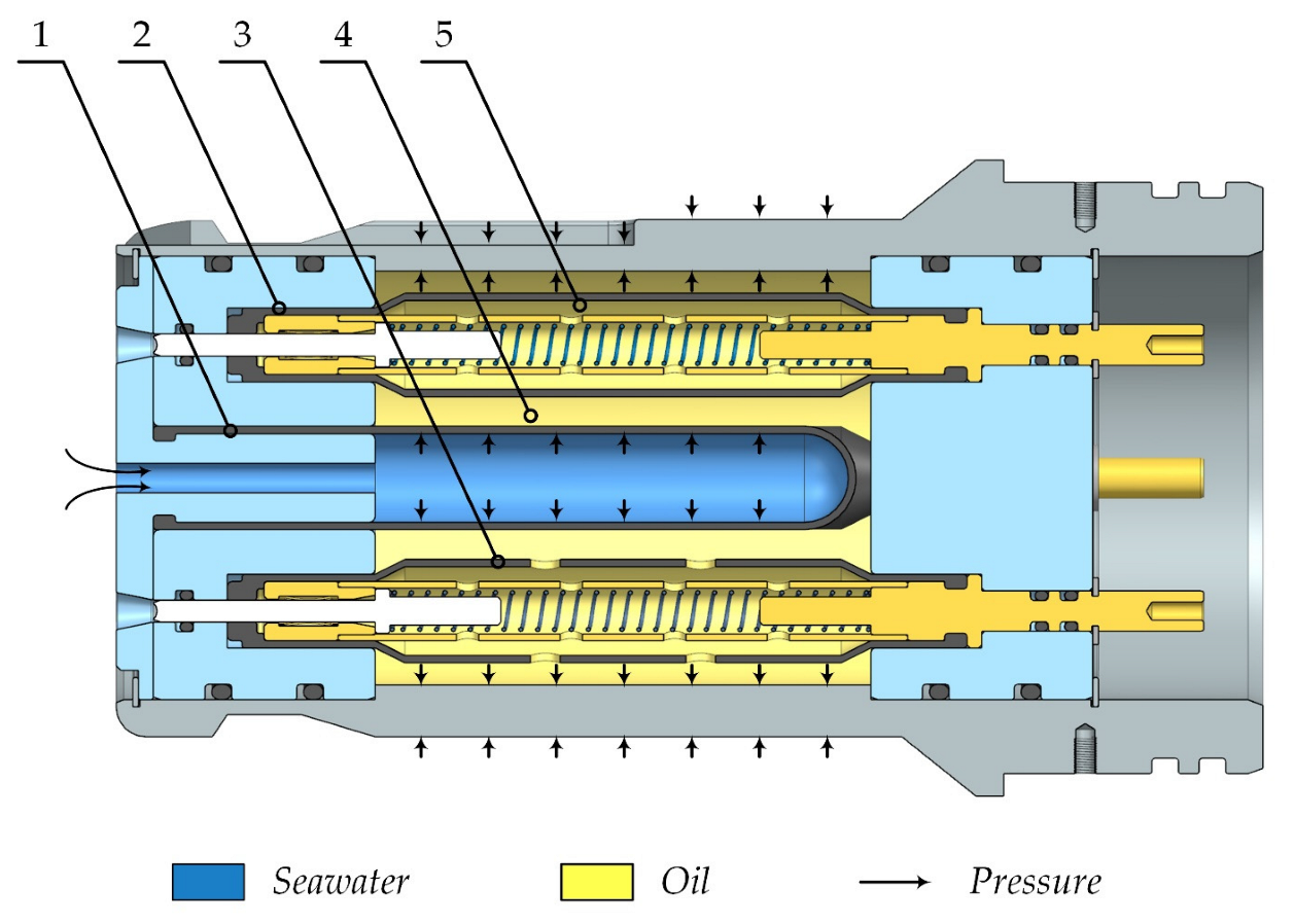
Figure 3 presents a schematic of the dual-bladder PBOF technology used in the proposed connector. The primary oil chamber is formed outside of the primary resilient bladder, while the independent secondary oil chambers are formed inside each secondary bladder. The oil chambers are all filled with the dielectric oil by a custom hypodermic tube of a syringe which can be inserted through each passageway of the moveable stopper. In the ocean, the primary bladder separates seawater and filled-oil. The ocean pressure can be transmitted to the oil in the primary oil chamber first and then to that in the secondary oil chamber, so an internal pressure is produced to balance the ocean pressure.
In particular, to fill the primary oil chamber, one secondary bladder must be punched through with holes to connect the primary oil chamber and its secondary oil chamber. So, this electrical channel protected by only one bladder can be used for unimportant circuits or ground terminals. The frequently used filled oil is the XIAMETER
TM PMX-200 silicon fluid (previously known as DC 200) produced by Dow Corning, which has good water-repellency, lubrication, and dielectric property [
3]. Fluorosilicone rubber is preferred to make such bladders that shall not react with silicone oil and seawater.
2.3. PBOF Theory
Due to the compressibility of oil, a differential pressure between the ambient pressure and the oil pressure will arise, which is a very important indicator of PBOF technology. The authors’ group has studied this problem systematically and the results are presented in a previous publication [
5]. On this basis, this paper further gives the generalized differential pressure equations of the dual-bladder PBOF technology. For the proposed connector, the differential pressure of the primary resilient bladder can be determined by the following equations.
where
P is the ocean pressure, in the unit of MPa;
ΔP1 is the differential pressure of the primary resilient bladder, in the unit of MPa;
E1 is the apparent elastic modulus of the primary resilient bladder, in the unit of MPa;
EB is the bulk modulus of the filled-oil, in the unit of MPa;
L0 is the length of the primary oil chamber, in the unit of mm;
L1 is the length of the primary resilient bladder, in the unit of mm;
R0 is the internal radius of the primary oil chamber, in the unit of mm;
R1 is the external radius of the primary resilient bladder, in the unit of mm;
δ1 is the thickness of the primary resilient bladder, in the unit of mm;
μ1 is the Poisson’s ratio of the primary resilient bladder.
Similarly, the differential pressure equation of the secondary resilient bladder can be obtained by the following equations.
where
ΔP2 is the differential pressure of the secondary resilient bladder, in the unit of MPa;
E2 is the apparent elastic modulus of the secondary resilient bladder, in the unit of MPa;
L2 is the length of the secondary resilient bladder, in the unit of mm;
R2 is the external radius of the secondary resilient bladder, in the unit of mm;
δ2 is the thickness of the secondary resilient bladder, in the unit of mm;
μ2 is the Poisson’s ratio of the secondary resilient bladder.
Therefore, the total differential pressure of the proposed connector is as follows:
For the proposed connector, we have
R0 = 28 mm,
L0 = 67 mm, and
EB = 1034 MPa. For two resilient bladders, we have
E1 =
E2 = 22 MPa,
R1 =
R2 = 7 mm,
δ1 =
δ2 = 1 mm,
μ1 =
μ2 = 0.5,
L1 = 65 mm, and
L2 = 67 mm. Then, the differential pressures of the proposed connector can be determined.
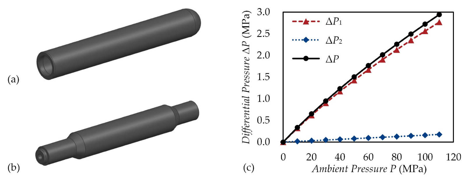
Figure 4 presents a three-dimensional (3D) view of two bladders, as well as the theoretical results of their differential pressures. The results are given as follows:
(1) The total differential pressure is mainly determined by the primary bladder, which is almost less than 3.5% of the ocean pressure.
(2) The differential pressure of the secondary bladder is much smaller than that of the primary bladder. This reminds us that the differential pressure provided by the bladder under the action of internal pressure is much larger than that provided by such a bladder with a similar dimension but under the action of external pressure.
(3) Although the dual-bladder PBOF technology can improve reliability, it may also increase the total differential pressure. Nevertheless, due to the pressure-balanced mode of the secondary bladder, there is only a slight impact on the performance.
2.4. Shuttle Pin Design
The shuttle pin design can provide the sealing performance in the dynamic process of mating and de-mating, which belongs to a penetrable seal-sealing [
3,
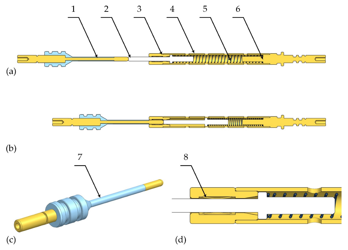
20]. As is depicted in
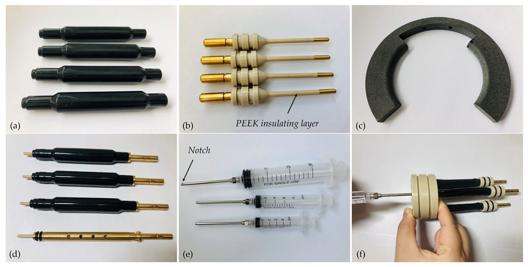
Figure 5, when the contact pin is inserted into the electric socket, it will push the moveable stopper inside and make full contact with the crown spring. Thus, the current will flow through the pin to the socket, and then to the conductive sleeve and the conductive shaft in turn. When the pin is de-mated, the stopper will be followed by the pin closely under the action of the spring force. Therefore, the sealing performance can always be guaranteed by this penetrable self-sealing design.
The shuttle pin design involves the following essential components and subtle design skills:
(1) The moveable stopper must be an insulating part, which is made of polyetheretherketone (PEEK). The diameter of the stopper is only 3 mm, which almost reaches the limit of commercial off-the-shelf (COTS) products. The stopper’s small size brings great challenges to the manufacturing and the penetrable self-sealing. Therefore, it presents one of the most difficult challenges in developing wet-mateable electrical connectors.
(2) The contact pin, as shown in
Figure 5c, has an insulating layer made of PEEK to prevent seawater from contacting the conductor after the intrusion, which is almost as expensive as the resilient bladder due to the difficulty of processing.
(3) The maximum deformation of the spring should satisfy the hypodermic tube of the syringe and can reach the position of oil-filling. Additionally, the authors recommend using the piano-wire spring which has good performance in strength and fatigue resistance.
(4) According to the requirement of the maximum operating current, the standard parts can be selected for the crown spring, which is usually made of beryllium copper. The other conductive components can be made of copper alloys, such as brass or lead brass. Moreover, gold plating can be used on the electrical contact surface to decrease contact resistance.
(5) An easily occurred and fatal failure mode of the shuttle pin design is that the moveable stopper cannot eject to the original position after de-mating. To avoid this, the end of the stopper and the end of the fitted hole in the electric socket are both designed as cone types, which are shown in
Figure 5d. This skill can also increase allowable fit tolerances to decrease the cost of manufacturing.
(6) It is worth noting that PEEK plastic is a very important dielectric material used in wet-mateable electrical connectors, which has good insulating properties in harsh environments under the sea. Also, PEEK is a self-lubricating material with higher tensile and yield strength and excellent fatigue resistance [
3].
3. Finite Element Analysis
3.1. Coupled Multi-Field Simulation
Due to the Joule heating effect, wet-mateable electrical connectors will inevitably generate heat when they transfer electricity. However, the excessive temperature will reduce the elasticity of electric contact and soften the insulating material, resulting in the failure of connection and insulation. Moreover, thermal stress may also cause a fatal effect on the reliability of the structure. For example, if high stress produces a large deformation of the moveable stopper, the function of the penetrable self-sealing will be totally lost. Therefore, the coupled multi-field simulation is indispensable for the development of wet-mateable electrical connectors.
Here, the basic equations of thermal-electric coupling are given as follows. Equations (8) and (9) are derived from the heat flow equation and the charge continuity equation respectively, and Equation (10) is the constitutive equation for the dielectric medium [
14,
21].
where
C is the specific heat capacity, in the unit of J/(kg·°C);
T is the absolute temperature, in the unit of °C;
q is the heat generation rate, in the unit of W/m3;
ρ is the density, in the unit of kg/m3;
D is the electric flux density vector, in the unit of C/m2;
E is the electric field intensity vector, in the unit of V/m;
J is the electric current density vector, in the unit of A/m2;
[Π] is the Peltier coefficient matrix, [Π] = T·[α], in the unit of V;
[α] is the Seebeck coefficient matrix, in the unit of V/°C;
[ε] is the dielectric permittivity matrix, in the unit of F/m;
[λ] is the thermal conductivity matrix, in the unit of W/m·°C;
[σ] is the electrical conductivity matrix, in the unit of S/m.
By applying the Galerkin FEM procedure to the above-derived coupled equations, the thermoelectric finite element equations can be obtained as follows [
14,
21]:
where
CTT is the thermal damping matrix;
Cφφ is the dielectric damping matrix;
KTT is the thermal stiffness matrix;
KφT is the Seebeck stiffness matrix;
Kφφ is the electric stiffness matrix;
I is the electric current load vector;
Q is the combined heat load vector;
Te is the nodal temperature vector;
φe is the nodal electric potential vector.
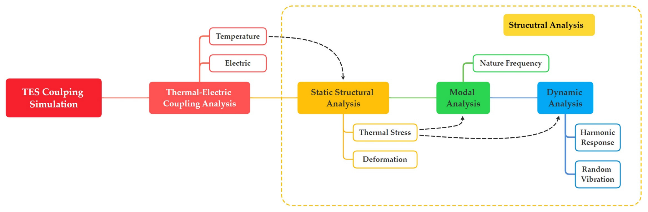
As is depicted in
Figure 6, the authors proposed a procedure of thermal-electric-structure (TES) coupling simulation for wet-mateable electrical connectors, which can be achieved by FEM based on ANSYS software. The interface of ANSYS Workbench can easily realize coupled-field analysis. First, an FEA model involving thermal-electric coupling is proposed to verify the thermoelectricity of the above-designed connector. Second, the obtained temperature distribution should be transferred to the static structural FEA model. Then, the thermal stress distribution can be determined to verify the reliability of the structure. Furthermore, the pre-stress in the structure cannot be ignored in dynamic analysis. Thus, thermal stress should be transferred to the FEA model of modal analysis. Only in this step can accurate dynamic analyses be done. The simulation results of the proposed connector will be presented and discussed next. All the material specifications used in the FEA models are listed in
Table 2, which are from ANSYS GRANTA Materials Database.
3.2. Thermal-Electric Coupling Analysis
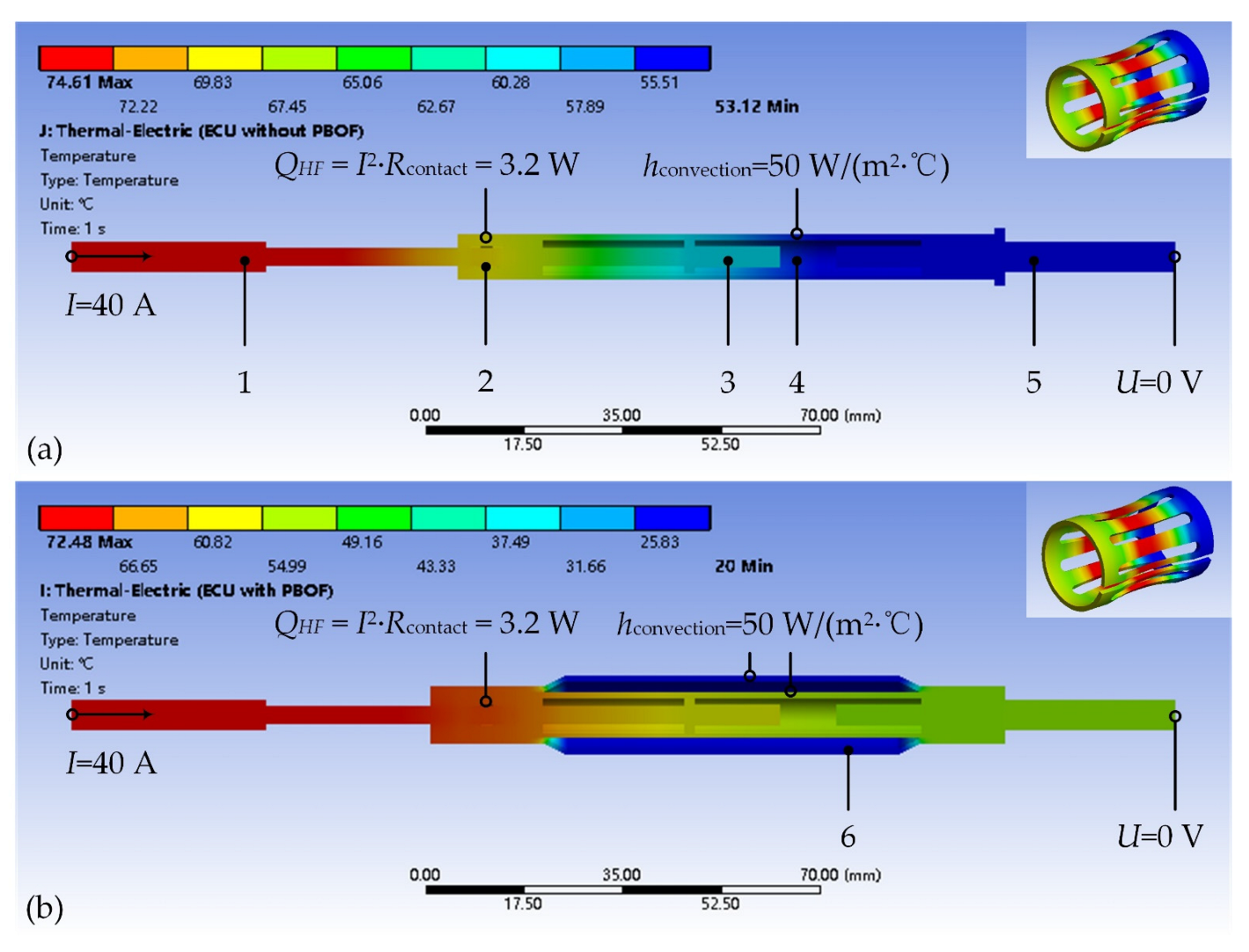
A thermal-electric coupling FEA model is proposed based on ANSYS Mechanical, and the corresponding boundary conditions include the following aspects:
(1) The current I is applied to the end-face of the contact pin (here I = 40 A). The voltage U of the end-face of the conductive shaft is set to be zero (U = 0).
(2) Due to the existence of contact resistance Rcontact, a heat flow QHF is applied on the surface of the electric contact (here, QHF = I2·Rcontact = 3.2 W).
(3) According to different conditions of the environment, the convective film coefficient hconvective is set on the corresponding heat dissipation surface.
To begin with,
Figure 7 presents the temperature distribution of the electric contact with PBOF technology, as well as corresponding boundary conditions. The results are shown as follows:
(1) The maximum temperature of the electric contact in
Figure 7a is about 74.61 °C, while it is decreased by 2.85% to about 72.48 °C in
Figure 7b. The maximum temperature of the crown spring in
Figure 7a is about 69.29 °C, while it is decreased by 3.09% to about 67.15 °C in
Figure 7b.
(2) Due to the higher convective film coefficient of oil, PBOF technology can improve the heat dissipation capability of the electric contact. Importantly, because the use of the secondary resilient bladder increases the area of dissipation, the dual-bladder PBOF technology can further reduce thermal power by about 3%.
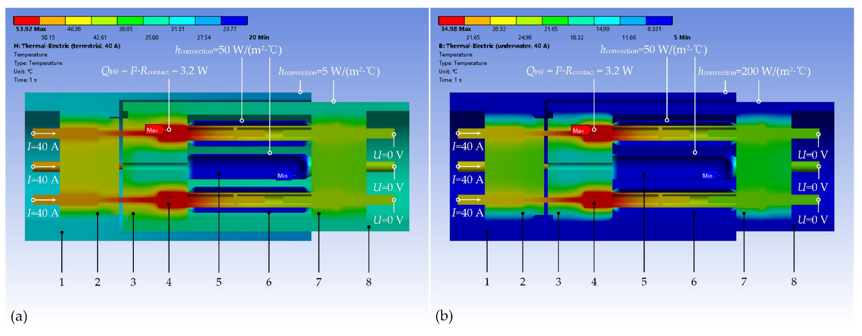
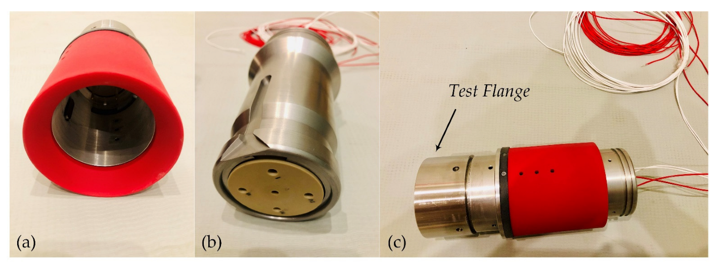
Figure 8 further gives the temperature distribution of the whole connector in terrestrial and underwater environments respectively, as well as the corresponding boundary conditions.
Figure 9 presents the electric field distribution of some insulating components in an underwater environment, as well as the corresponding maximum intensity
Emax. The results are shown as follows:
(1) The maximum temperature of the proposed connector in a terrestrial environment is about 53.92 °C, while it is decreased by about 35.17% to 34.98 °C in the underwater environment. The maximum temperature in both cases appears on the contact pin.
(2) The ambient temperature under the sea is much lower than the terrestrial temperature. Also, the convective film coefficient of seawater is much larger than that of air. This allows better heat dissipation of wet-mateable electrical connectors in the operating condition, which can further be improved by the dual-bladder PBOF technology. As a result, the overcurrent capacity of the proposed connector will exceed the rated current of the crown spring.
(3) The receptacle front pedestal has the strongest electric field with an intensity of 21.8 kV/mm, which almost reaches the breakdown field of PEEK. The electric field intensities of other insulating components are much smaller. The analysis of thermoelectric performance further confirms that the maximum operating current of the proposed connector can reach 40 A.
To this extent, the thermal-electric coupling analysis further reveals a characteristic of wet-mateable electrical connectors, that is, the overcurrent capacity can be enhanced by the underwater environment and PBOF technology. Therefore, we revised the maximum operating current in
Table 1 as follows: 30 A in dry conditions and 40 A under the sea. Moreover, the glass fibre-reinforced PEEK can be used to provide better resistance to dielectric breakdown.
3.3. Static Structural Analysis
A static structural FEA model based on ANSYS Mechanical is proposed. The obtained temperature distribution from the thermal-electric analysis is coupled with this FEA model to calculate the thermal stress.
Figure 10 presents the stress distribution of some core components, as well as the corresponding maximum stress
σmax. The results are shown as follows:
(1) The components having large deformation are the resilient bladders, and the maximum deformation is about 0.97 mm which has no influence on the reliability of the structure. The deformation of the moveable stopper is just about 0.02 mm at maximum, which has no effect on the function of the shuttle pin design.
(2) The components having large thermal stress are the contact pins, and the maximum equivalent stress is about 123.44 MPa which is less than the yield stress of copper alloy. The equivalent stress of the crown spring is about 24.45 Mpa in maximum, which has no effect on its elasticity. The thermal stress of the moveable stopper is much smaller.
In this subsection, a static structural FEA model of the AID technology is also proposed to verify the performance and provide guidance for the selection of the latching member’s material.
Figure 11 presents the mating process in the simulation, and
Figure 12 gives the change curves of the mating/de-mating force and the equivalent stress of the latching member. The results are given as follows:
(1) The latching member must have the appropriate elastic constants. If the Young’s modulus of the material is too small, it cannot provide enough locking force, while if Young’s modulus is too large, the mating force will be increased. According to the simulation results, the material with Young’s modulus of about 70 MPa is the ideal material for the latching member.
(2) The de-mating force of the proposed AID technology is about 66.50 N, while the mating force is about 31.01 N. The de-mating force should be appropriately larger than the mating force, which can achieve easy docking and reliable interlocking of the wet-mateable connectors.
3.4. Dynamic Analysis
A pre-stress FEA model of modal analysis based on ANSYS Mechanical is proposed. The obtained thermal stress distribution from the TES coupling analysis is transferred to this FEA model. The results are given as follows:
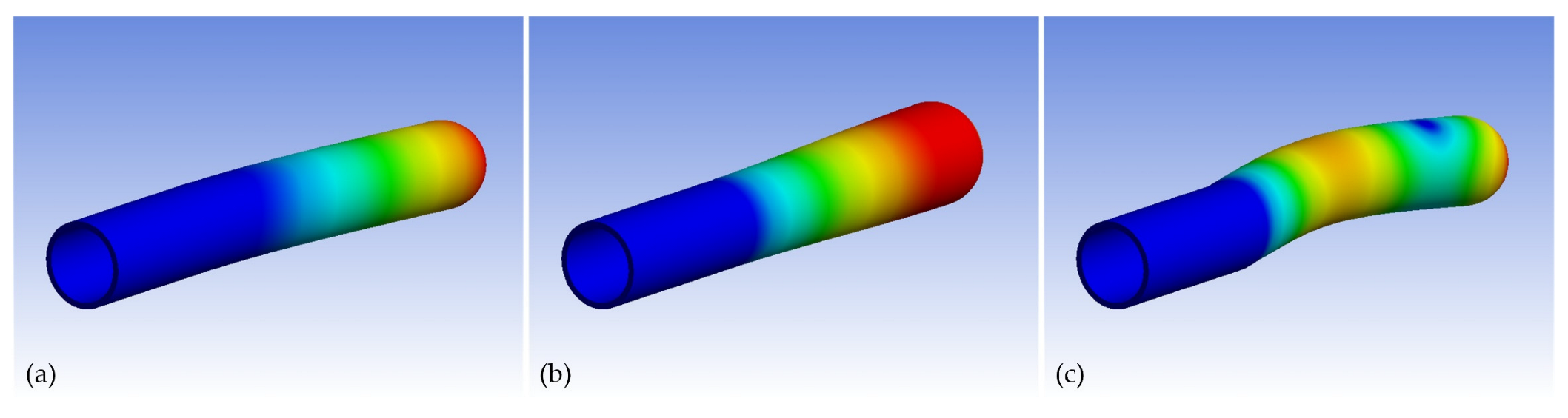
(1) The natural frequencies of the proposed connector are around 24.2 Hz, 75.4 Hz, 96.2 Hz and 113.6 Hz, which should be avoided in the operating condition in engineering practice.
(2) The inherent vibration is concentrated on the primary resilient bladder, which indicates that the primary bladder has a good effect on vibration attenuation. Some typical mode shapes of the primary bladder are shown in
Figure 13.
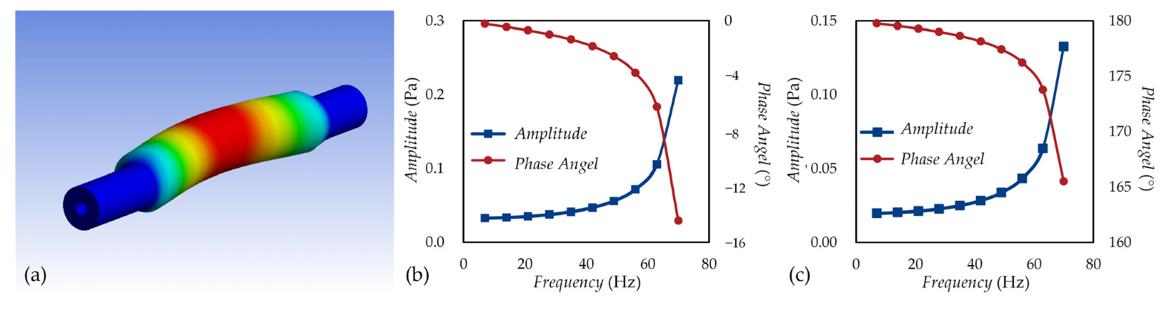
Moreover, a pre-stress FEA model of harmonic response based on ANSYS Mechanical is also proposed. The obtained thermal stress distribution from the TES coupling analysis is transferred to this FEA model, too. The frequency spacing ranges from 0 Hz to 70 Hz.
Figure 14 gives the mode shape and the frequency response of the secondary resilient bladder. The results show that the harmonic response is concentrated on the secondary resilient bladder. Therefore, we can realize another advantage of the proposed dual-bladder PBOF technology; that is, the primary bladder has the function of inherent vibration attenuation, while the secondary bladder has the function of harmonic vibration attenuation.
5. Discussion and Conclusions
This paper presents a methodology for designing and testing a wet-mateable electrical connector, which might be the first discloser on this topic in the aspects of design, theory, simulation and testing. The innovations of the proposed connector can be summarized as follows:
(1) The dual-bladder PBOF design used in the proposed connector is mainly based on the low-cost primary resilient bladder, which is different from some COTS products’ designs (e.g., SECAON HydraElectric, NautilusTM WM1.7-30 and Siemens DigiTRON). The bladders used in COTS products are often very large, which are usually very difficult to manufacture by injection moulding.
(2) The AID design used in the proposed connector is also different from what is used in NautilusTM WM1.7-30 and Siemens DigiTRON. Also, the latching member can be made directly by 3D printing, which is cost-effective.
(3) In fact, the cost of developing a wet-mateable connector is very high. We have almost reached the limit of cost control in the R&D process. From another perspective, with lower cost and a shorter development cycle, we have made some major breakthroughs in this bottleneck field in China, and this benefited from the previous review research and the use of innovative simulation techniques.
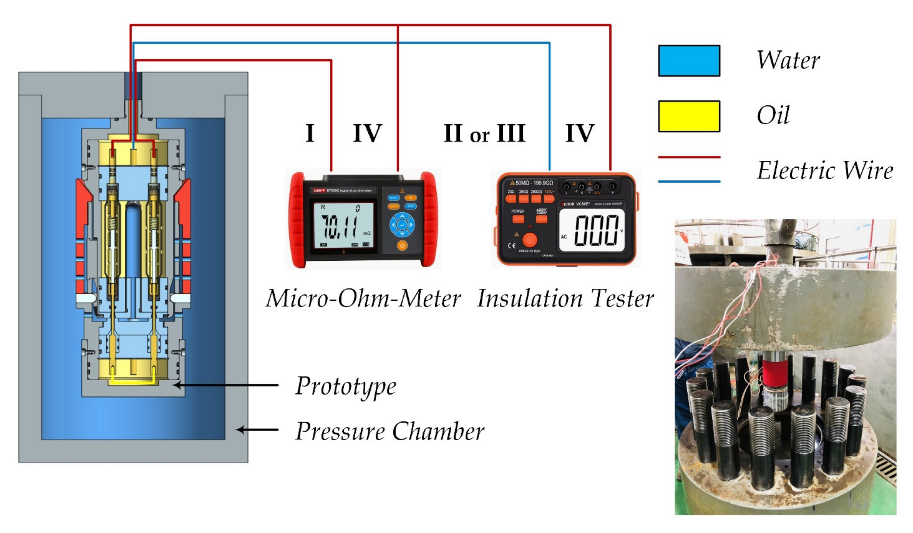
It should be noted that the wet-mating online test of electrical performance in a high-pressure environment has not been carried out in this paper. To realize the wet-mating operation in a high-pressure environment, a specially-customed pressure chamber should be required. Unfortunately, such equipment is unavailable to us at present, which also involves a lot of key technologies. Limited by our financial conditions, the depth rate of the prototype and the test condition can only reach the present level, which can be improved in the future.
The main conclusions can be summarized as follows:
(1) An innovative wet-mateable connector has been proposed, which involves the dual-bladder PBOF technology, the penetrable self-sealing design, and the AID technology.
(2) The generalized differential pressure equations of the dual-bladder PBOF technology have been derived. The results show that the differential pressure provided by the bladder under the action of internal pressure is much larger than that provided by such a bladder with a similar dimension but under the action of external pressure.
(3) A procedure of thermal-electric-structure (TES) coupling simulation for wet-mateable electrical connectors has been proposed, and a series of FEA involving coupled multi-field problems have been conducted, including thermal-electric coupling analysis, static structural analysis, and dynamic analysis. The results show that the underwater environment allows better heat dissipation of wet-mateable electrical connectors, which can further be improved by the dual-bladder PBOF technology. Also, the primary resilient bladder has the function of inherent vibration attenuation while the secondary resilient bladder has the function of harmonic vibration attenuation.
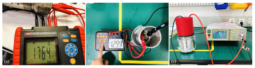
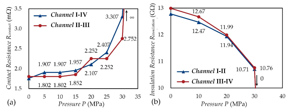
(4) A prototype of the proposed connector has been developed successfully, and many process problems of core components have been solved. The electrical performance of the prototype has been verified by the online test in the hydrostatic pressure environment with an ocean depth of 3000 m. The technical level has reached the leading position in China.
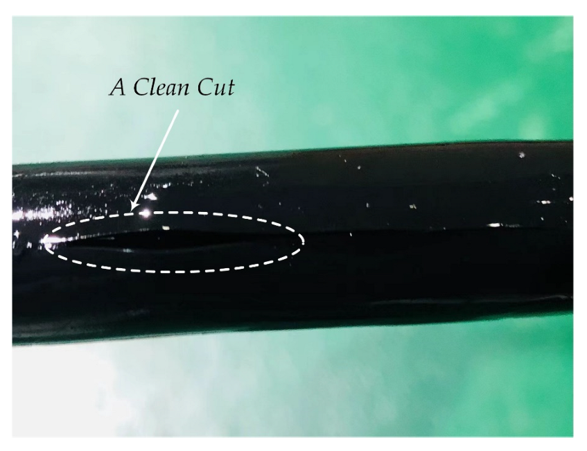
(5) The failure modes of wet-mateable connectors have been revealed, mainly including the sealing failure and the PBOF failure. The rod seals with high sealing pressure should be used in the shuttle pin design. The woven fabric-reinforced fluorosilicone rubber can be used to make resilient bladders to improve the reliability of PBOF technology. Additionally, the glass fibre-reinforced PEEK can be used to provide better resistance to dielectric breakdown.


 ,
, 


