
Effect of Flow Rate on Regular Patterns of Pressure Load Distribution on Helico-Axial Pump Impeller Blade Surface

Abstract
:1. Introduction
2. Prototype Pump
3. Numerical Methods
3.1. Governing Equations
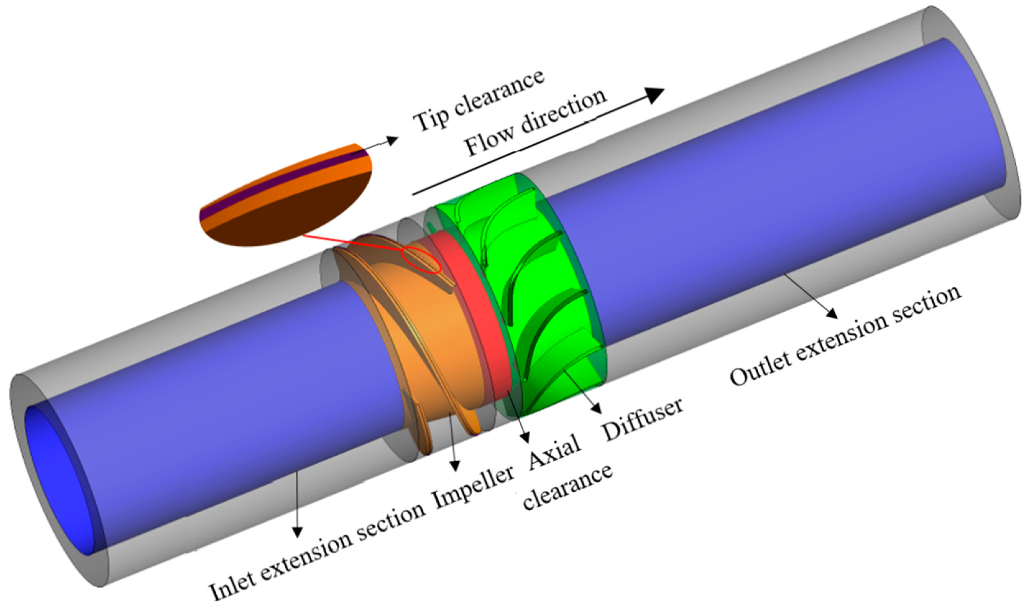
3.2. Model of Helico-Axial Pump
3.3. Mesh Arrangement and Mesh Independence Validation
3.4. Numerical Simulation Setting
3.5. Numerical Method Verification
4. Result Analysis
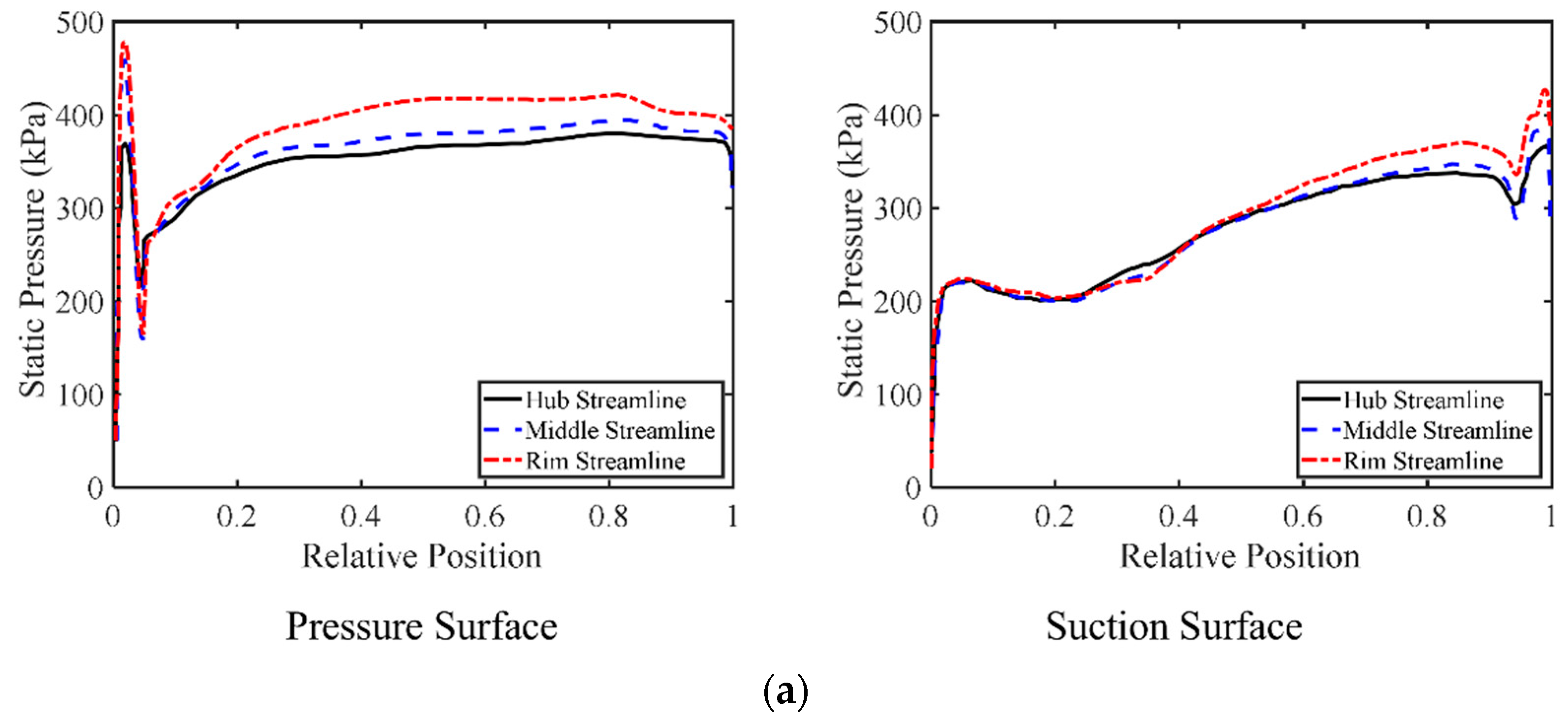
4.1. Static Pressure Distribution of Impeller Blade Surface under Different Flow Rates
4.2. Pressure Load Distribution of Impeller Blade under Different Flow Rate
5. Conclusions
- (1)
- With the increase of flow rate, the head of both the helico-axial pump and impeller gradually decreases, while the hydraulic efficiency of the helico-axial pump increases first and decreases then with a gradual lowering of impeller efficiency. Moreover, with the increase in flow rate, the decreased rate of the impeller hydraulic efficiency under the working condition of a large flow rate is apparently higher than that under the working condition of a small flow rate.
- (2)
- The static pressure difference between each streamline of the helico-axial pump impeller working surface under the working condition of a small flow rate is significantly larger than that under the working condition of a large flow rate. With the increase in flow rate, the lowest point of static pressure on the back surface of the helico-axial pump blade at different blade heights gradually shifts from the relative position of 0.2 to 0.4, and the low-pressure area gradually expands.
- (3)
- Under different flow rates, the pressure load distribution curves of the impeller blade surface at different blade heights all show the trend of increasing first and decreasing then. In the impeller inlet area, with the increase in flow rate, the range of negative blade pressure load in the area gradually expands. Under the working condition of a small flow rate, the work capacity of the hub is significantly stronger than other areas of the impeller within the range of relative position of 0~0.2, and the work capacity gradually increases from hub to rim within the range of relative position of 0.2~1. With the increase in flow rate, the area of the strong work capacity of the hub gradually expands while the area of the strong work capacity of the rim gradually narrows.
Author Contributions
Funding
Institutional Review Board Statement
Informed Consent Statement
Data Availability Statement
Conflicts of Interest
References
- Saadawi, H. An overview of multiphase pumping technology and its potential application for oil fields in the gulf region. In Proceedings of the International Petroleum Technology Conference, Dubai, United Arab Emirates, 4–6 December 2007. [Google Scholar]
- Falcimaigne, J.; Brac, J.; Charron, Y.; Pagnier, P.; Vilaginès, R. Multiphase Pumping: Achievements and Perspectives. Oil Gas Sci. Technol. 2002, 57, 99–107. [Google Scholar] [CrossRef] [Green Version]
- Ming, L.; Lei, T.; Shuliang, C. Method of dynamic mode decomposition and reconstruction with application to a three-stage multiphase pump. Energy 2020, 208, 1118343. [Google Scholar]
- Kim, J.H.; Lee, H.C.; Kim, J.H.; Choi, Y.S.; Yoon, J.Y.; Yoo, I.S.; Choi, W.C. Improvement of Hydrodynamic Performance of a Multiphase Pump Using Design of Experiment Techniques. J. Fluids Eng. 2015, 137, 081301. [Google Scholar] [CrossRef]
- Wang, J.; Zha, H.; McDonough, J.; Zhang, D. Analysis and numerical simulation of a novel gas–liquid multiphase scroll pump. Int. J. Heat Mass Transf. 2015, 91, 27–36. [Google Scholar] [CrossRef]
- Shi, Y.; Zhu, H.; Zhang, J.; Zhang, J.; Zhang, J. Experiment and numerical study of a new generation three-stage multiphase pump. J. Pet. Sci. Eng. 2018, 169, 471–484. [Google Scholar] [CrossRef]
- Zhang, J.; Zhu, H.; Yang, C.; Li, Y.; Wei, H. Multi-objective shape optimization of helico-axial multiphase pump impeller based on NSGA-II and ANN. Energy Convers. Manag. 2011, 52, 538–546. [Google Scholar] [CrossRef]
- Suh, J.W.; Kim, J.H.; Choi, Y.S.; Joo, W.G.; Lee, K.Y. A study on numerical optimization and performance verification of multiphase pump for offshore plant. Proc. Inst. Mech. Eng. Part A J. Power Energy 2017, 231, 382–397. [Google Scholar] [CrossRef]
- Shi, G.; Liu, Z.; Xiao, Y.; Yang, H.; Li, H.; Liu, X. Effect of the inlet gas void fraction on the tip leakage vortex in a multiphase pump. Renew. Energy 2020, 150, 46–57. [Google Scholar] [CrossRef]
- Liu, M.; Tan, L.; Xu, Y.; Cao, S. Optimization design method of multi-stage multiphase pump based on Oseen vortex. J. Pet. Sci. Eng. 2019, 184, 106532. [Google Scholar] [CrossRef]
- Kim, S.; Kim, Y.I.; Kim, J.H.; Choi, Y.S. Three-objective optimization of a mixed-flow pump impeller for improved suction performance and efficiency. Adv. Mech. Eng. 2020, 11, 7–40. [Google Scholar] [CrossRef]
- Xu, Y.; Cao, S.; Sano, T.; Wakai, T.; Reclari, M. Experimental Investigation on Transient Pressure Characteristics in a Helico-Axial Multiphase Pump. Energies 2019, 12, 461. [Google Scholar] [CrossRef]
- Zhang, J.; Cai, S.; Zhu, H.; Zhang, Y. Experimental investigation of the flow at the entrance of a rotodynamic multiphase pump by visualization. J. Pet. Sci. Eng. 2015, 126, 254–261. [Google Scholar] [CrossRef]
- Zhang, J.; Cai, S.; Li, Y.; Zhu, H.; Zhang, Y. Visualization Study of Gas-Liquid Two-Phase Flow Patterns inside a Three-Stage Rotodynamic Multiphase Pump. Exp. Therm. Fluid Sci. 2016, 70, 125–138. [Google Scholar] [CrossRef]
- Liu, M.; Tan, L.; Cao, S. Design method of controllable blade angle and orthogonal optimization of pressure rise for a multiphase pump. Energies 2018, 11, 1048. [Google Scholar] [CrossRef] [Green Version]
- Zhang, J.-X.; Zhang, J.-Y.; Zhou, Y.; Cheng, Z.-Y.-Y.; Cap, G.-D. Investigation on the performance of a helico-axial multiphase pump under slug flow. Pet. Sci. 2022, 19, 1812–1824. [Google Scholar] [CrossRef]
- Suh, J.W.; Kim, J.W.; Choi, Y.S.; Kim, J.Y.; Joo, W.G.; Lee, K.Y. Development of numerical Eulerian-Eulerian models for simulating multiphase pumps. J. Pet. Sci. Eng. 2018, 162, 588–601. [Google Scholar] [CrossRef]
- Cao, F.; Gao, T.; Li, S.; Xing, Z.; Shu, P. Experimental analysis of pressure distribution in a twin screw compressor for multiphase duties. Exp. Therm. Fluid Sci. 2011, 35, 219–225. [Google Scholar] [CrossRef]
- Xiao, Y.; Gui, Z.; Li, X.; Shu, Z.; Shi, G.; Gu, C. Numerical Investigation of Gas-Liquid Flow in a Multiphase Pump with Special Emphasis on the Effect of Tip Leakage Vortex on the Gas Flow Pattern. J. Mar. Sci. Eng. 2022, 10, 1665. [Google Scholar] [CrossRef]
- Yu, Z.; Zhu, B.; Cao, S. Interphase force analysis for air-water bubbly flow in a multiphase rotodynamic pump. Eng. Comput. 2015, 32, 2166–2180. [Google Scholar] [CrossRef] [Green Version]
- Cao, S.; Peng, G.; Yu, Z. Hydrodynamic Design of Rotodynamic Pump Impeller for Multiphase Pumping by Combined Approach of Inverse Design and CFD Analysis. J. Fluids Eng.-Trans. ASME 2005, 127, 330–338. [Google Scholar] [CrossRef]
- Quan, H.; Li, Y.; Kang, L.; Yu, X.; Song, K.; Wu, Y. Influence of Blade Type on the Flow Structure of a Vortex Pump for Solid-Liquid Two-Phase Flow. Machines 2021, 9, 353. [Google Scholar] [CrossRef]
- Li, D.; Zhu, Y.; Lin, S.; Gong, R.; Wang, H.; Luo, X. Cavitation effects on pressure fluctuation in pump-turbine hump region. J. Energy Storage 2022, 47, 103936. [Google Scholar] [CrossRef]
- Li, X.; Gao, P.; Zhu, Z.; Li, Y. Effect of the blade loading distribution on hydrodynamic performance of a centrifugal pump with cylindrical blades. J. Mech. Sci. Technol. 2018, 32, 1161–1170. [Google Scholar] [CrossRef]
- Shi, G.; Yan, D.; Liu, X.; Xiao, Y.; Shu, Z. Effect of the Gas Volume Fraction on the Pressure Load of the Multiphase Pump Blade. Processes 2021, 9, 650. [Google Scholar] [CrossRef]
- Zhang, M.; Tsukamoto, H. Unsteady Hydrodynamic Forces due to Rotor-Stator Interaction on a Diffuser Pump with Identical Number of Vanes on the Impeller and Diffuser. J. Fluids Eng.-Trans. ASME 2005, 127, 743–751. [Google Scholar] [CrossRef]
- Zhou, L.; Shi, W.; Wei, L.; Agarwal, R. Numerical and Experimental Study of Axial Force and Hydraulic Performance in a Deep-Well Centrifugal Pump with Different Impeller Rear Shroud Radius. J. Fluids Eng.-Trans. ASME 2013, 135, 104501. [Google Scholar] [CrossRef]
- Li, J.W.; Zhang, Y.N.; Liu, K.H.; Xian, H.Z.; Yu, J.X. Numerical simulation of hydraulic force on the impeller of reversible pump turbines in generating mode. J. Hydrodyn. 2017, 29, 603–609. [Google Scholar] [CrossRef]
- Zhu, D.; Xiao, R.; Liu, W. Influence of leading-edge cavitation on impeller blade axial force in the pump mode of reversible pump-turbine. Renew. Energy 2021, 163, 939–949. [Google Scholar] [CrossRef]
- Kang, C.; Zhu, Y.; Li, Q. Effects of hydraulic loads and structure on operational stability of the rotor of a molten-salt pump. Eng. Fail. Anal. 2020, 117, 104821. [Google Scholar] [CrossRef]
- Zhou, W.; Wang, Y.; Li, C.; Zhang, W.; Wu, G. Analysis of fluid-induced force of centrifugal pump impeller with compound whirl. Alex. Eng. J. 2021, 59, 4247–4255. [Google Scholar] [CrossRef]
- Shi, G.; Zhu, Z.; Wang, B.; Wen, H. Effect of the Gap Matching Relation on the Pressure Pulsation Characteristics at Blade’s Surface of the Multiphase Pump. Machines 2022, 10, 418. [Google Scholar] [CrossRef]
- Liu, M.; Tan, L.; Cao, S. Theoretical model of energy performance prediction and BEP determination for centrifugal pump as turbine. Energy 2019, 172, 712–732. [Google Scholar] [CrossRef]
- Wilcox, D.C. Turbulence Modeling for CFD; DCW Industries: La Canada, CA, USA, 1998. [Google Scholar]
- Menter, F.R. Two-equation eddy-viscosity turbulence models for engineering applications. AIAA J. 1994, 32, 1598–1605. [Google Scholar] [CrossRef]


| Parameters | Value | Unit |
|---|---|---|
| Design volume flow rate | 90 | m3/h |
| Design rotational speed | 3600 | r/min |
| Number of impeller blade | 3 | - |
| Number of diffuser blade | 11 | - |
| Outer diameter of impeller | 161 | mm |
| Outer diameter of diffuser | 161 | mm |
| Group 1 | Group 2 | Group 3 | Group 4 | |
|---|---|---|---|---|
| number of grids in inlet extension (106) | 0.51 | 0.51 | 0.51 | 0.51 |
| number of grids in impeller (106) | 0.78 | 1.20 | 1.75 | 2.60 |
| number of grids in diffuser (106) | 0.61 | 0.97 | 1.44 | 2.08 |
| number of grids in outlet extension (106) | 0.56 | 0.56 | 0.56 | 0.56 |
| number of total grids (106) | 2.46 | 3.24 | 4.26 | 5.75 |
| H/H1 | 1 | 1.021 | 1.036 | 1.040 |
| Instrument | Range | Precision | Unit |
|---|---|---|---|
| Inlet pressure gauge | 0–0.8 | 0.3 class | MPa |
| Outlet pressure gauge | 0–1 | ±0.2% | MPa |
| Water flow meter | 0–140 | ±0.5% | m3/h |
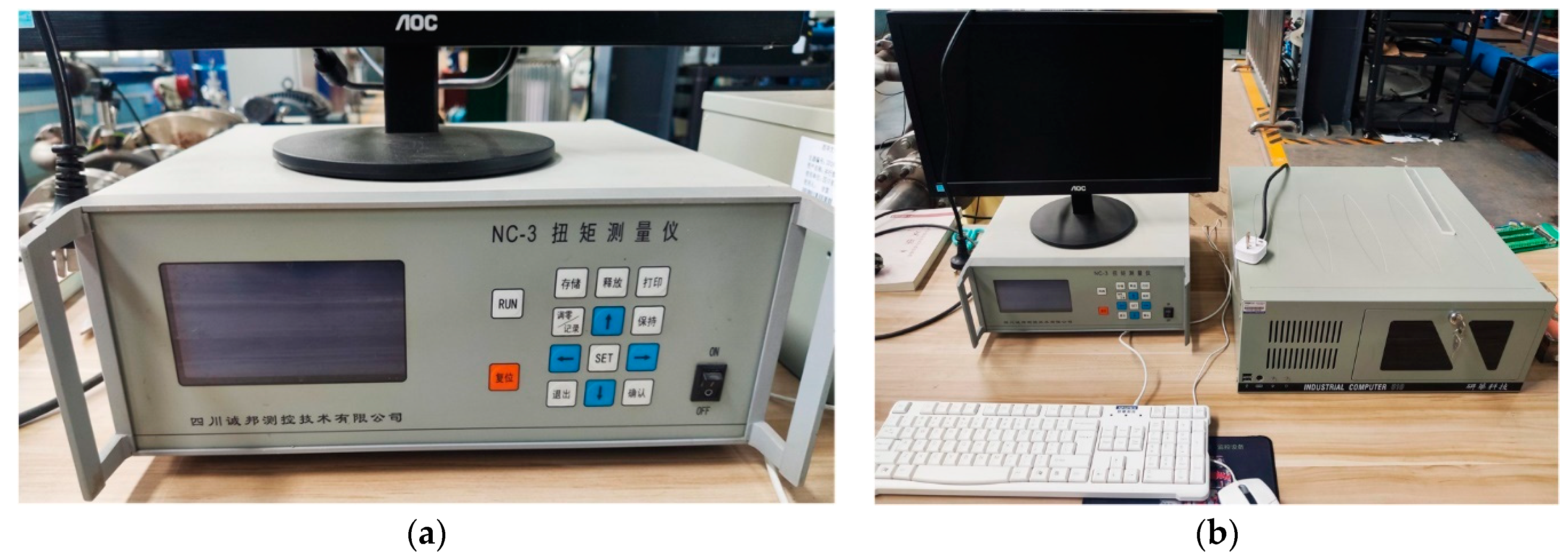
| Torquemeter | 0–50 | 0.2 class | N·m |
Disclaimer/Publisher’s Note: The statements, opinions and data contained in all publications are solely those of the individual author(s) and contributor(s) and not of MDPI and/or the editor(s). MDPI and/or the editor(s) disclaim responsibility for any injury to people or property resulting from any ideas, methods, instructions or products referred to in the content. |
© 2022 by the authors. Licensee MDPI, Basel, Switzerland. This article is an open access article distributed under the terms and conditions of the Creative Commons Attribution (CC BY) license (https://creativecommons.org/licenses/by/4.0/).
Share and Cite
Huang, Z.; Shi, G.; Wen, H. Effect of Flow Rate on Regular Patterns of Pressure Load Distribution on Helico-Axial Pump Impeller Blade Surface. J. Mar. Sci. Eng. 2023, 11, 13. https://doi.org/10.3390/jmse11010013
Huang Z, Shi G, Wen H. Effect of Flow Rate on Regular Patterns of Pressure Load Distribution on Helico-Axial Pump Impeller Blade Surface. Journal of Marine Science and Engineering. 2023; 11(1):13. https://doi.org/10.3390/jmse11010013
Chicago/Turabian StyleHuang, Zongliu, Guangtai Shi, and Haigang Wen. 2023. "Effect of Flow Rate on Regular Patterns of Pressure Load Distribution on Helico-Axial Pump Impeller Blade Surface" Journal of Marine Science and Engineering 11, no. 1: 13. https://doi.org/10.3390/jmse11010013