Article

Near-Optimal Control for Offshore Structures with Nonlinear Energy Sink Mechanisms

1
College of Automation and Electronic Engineering, Qingdao University of Science and Technology, Qingdao 266061, China
2
College of Science, China Jiliang University, Hangzhou 310018, China
3
College of Engineering, Ocean University of China, Qingdao 266100, China
*
Author to whom correspondence should be addressed.
J. Mar. Sci. Eng. 2022, 10(6), 817; https://doi.org/10.3390/jmse10060817
Submission received: 10 April 2022 / Revised: 5 June 2022 / Accepted: 10 June 2022 / Published: 14 June 2022
(This article belongs to the Special Issue Hydrodynamics of Offshore Structures)

Abstract

:
To improve the safety and reliability of offshore structures subject to wave loading, the active vibration control problem is always one of significant issues in the field of ocean engineering. This paper deals with the near–optimal control problem of offshore structures with a nonlinear energy sink (NES) mechanism. By taking the dominant vibration mode of the offshore structure with the NES into account, a nonlinear dynamic model of the steel–jacket structure subject to wave loading is presented first. Then, using the parameter perturbation approach to solve a nonlinear two–point boundary value problem, an NES–based optimal controller with the form of infinite series sum is presented to suppress the vibration of the offshore structure. Third, an iteration algorithm is provided to obtain the near–optimal controller. Simulation results demonstrate that the NES–based near–optimal controller can mitigate the oscillation amplitude of offshore structures significantly. Moreover, the NES–based optimal controller outperforms the one based on active tuned mass damper.

1. Introduction

Offshore structures are generally located in a complex marine environment and suffer a variety of external loads such as wind, waves, earthquakes and currents [1,2,3,4]. It is known that these loads may cause the offshore structures to experience continuous vibrations, which affects the service life of the platform and even threaten the lives of staff. To suppress the vibrations and guarantee the safety of the offshore structures, passive and/or active control of offshore structures has aroused more and more attention, and several control schemes, such as nonlinear and robust control [1,5], optimal control [6], sampled-data control [7,8], delayed dynamic output feedback control [9], sliding mode control [9,10], and networked control [11,12], have been reported. A more detailed review of the vibration control of offshore structure can be found in [13,14,15,16], and the references therein. Most recently, for a floating-type platform, an active-tuned heave-plate mechanism is presented and then an event-triggered robust control scheme is developed for those platforms subject to deception attacks.
Note that the aforementioned active control strategies are mainly based on a tuned mass damper and a tuned liquid damper device. In fact, these mechanisms are extensively used to reduce the vibration of offshore structures in a passive and/or active manner. It is not difficult to find that such devices are generally treated as a linear component and are made use of for vibration absorbers. In other words, such dynamic vibration absorbers are the strength of linear damping systems. It is believed that the linear characteristics of the system are simple to realize. However, the damping effects of the system may be limited to some degree. Therefore, a natural question is that, in order to further improve the performance of the offshore structures, are there any other devices with nonlinear characteristics for vibration suppression? To answer this question is our main motivation in this study.
In recent years, as one of the novel types of nonlinear dynamic vibration absorbers, nonlinear energy sink (NES) has attracted much attention in passive and/or active structural vibration areas [17,18,19,20,21]. Contrary to the classic dynamic vibration absorber, i.e, the tuned mass damper (TMD), NES has no fixed frequency because of the introduced nonlinear rigidity. In fact, it is found that the NES mechanism has better robustness against detuning and the potential ability of resonance capture cascading [22,23]. Thus, vibration suppression via a nonlinear vibration system can be further realized. It has been demonstrated that the NES is effective in suppressing the vibration of structure systems, and different types of NES, such as hysteretic NES [24], tuned bistable NES [25], and lever-type NES [26] have been proposed. In addition, NES–based vibration absorbers have been investigated and applied in several practical systems. For example, the flywheel system vibration reduction [27], nonlinear fluid-conveying pipe [28], panel flutter suppression [29], coupled oscillators [30], vibration suppression of nonlinear beams [31], and so on. Most recently, the NES mechanism is introduced to mitigate the vibration of offshore wind turbine towers [32,33]. Specifically, an NES is introduced as a passive device to control the vibration of offshore structures subject to wave loading [34], where a comparative analysis of the damping performance of NES and TMD has been made. It is shown that compared with the TMD, the NES can achieve better damping effects on the offshore structure. Due to the robustness of the vibration frequency and efficiency of vibration damping, there is a great development and utilizing prospect of the active control of the offshore structure.
In this paper, an active NES mechanism is introduced to control the marine structure in the presence of wave loading. First, based on the active NES mechanism, a nonlinear vibration model of the offshore platform is established. Then, NES-based optimal control scheme under finite horizon is proposed. Third, using parametric perturbation approach [35], a numerical algorithm is developed to design the near-optimal controller. Simulation results are provided to demonstrate the effectiveness of NES-based optimal controller and the superiority over the TMD-based optimal controller for the offshore structure.
The rest of the paper is organized as follows: the next section formulates the optimal control problem, where a nonlinear dynamic model of the offshore structure with an NES is presented, and a quadratic performance index functional under finite horizon is given. In Section 3, an NES–based optimal control scheme is developed, and a numerical algorithm is derived to compute the near–optimal controller. In Section 4, simulation results are given to show the effectiveness and advantages of the presented control scheme. The main conclusions are summarized in Section 5.

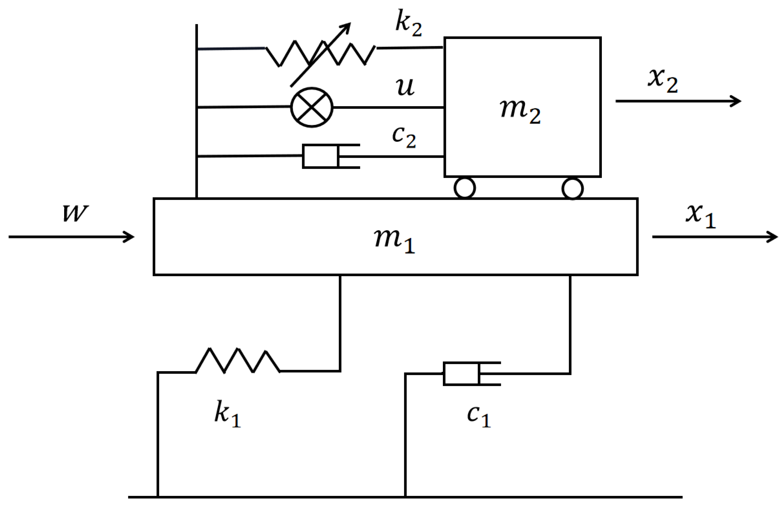
2. Problem Formulation

The offshore structure with an active NES mechanism considered in this paper is depicted in Figure 1, where the first vibration mode of the offshore structure equipped with an NES is adopted to describe dynamic characteristics of the structure vibration system. By Newton’s second law of motion, the dynamic equation of the offshore structure can be expressed as
m 1 x ¨ 1 = c 2 ( x ˙ 1 x ˙ 2 ) k 2 ( x 1 x 2 ) 3 u ( t ) c 1 x ˙ 1 k 1 x 1 + w ( t ) m 2 x ¨ 2 = c 2 ( x ˙ 1 x ˙ 2 ) k 2 ( x 2 x 1 ) 3 + u ( t )
where m 1 , c 1 and k 1 are the mass, damping, and stiffness of the first vibration mode of the platform, respectively; m 2 , c 2 , and k 2 represent the mass, damping and stiffness of the NES, respectively; x 1 and x 2 represent displacements of the structure and the NES, respectively; u ( t ) is the control input, and w ( t ) is the external wave load acting on the structure.
Let
z 1 ( t ) = x 1 ( t ) , z 2 ( t ) = x ˙ 1 ( t ) , z 3 ( t ) = x 2 ( t ) , z 4 ( t ) = x ˙ 2 ( t )
and denote
z ( t ) = [ z 1 ( t ) z 2 ( t ) z 3 ( t ) z 4 ( t ) ] T
Then from (1), one yields the state space model of the structure as
z ˙ ( t ) = A z ( t ) + B u ( t ) + H f ( z ( t ) ) + D w ( t )
where f ( z ) = ( z 1 z 3 ) 3 and
A = 0 1 0 0 k 1 m 1 c 1 + c 2 m 1 0 c 2 m 1 0 0 0 1 0 c 2 m 2 0 c 2 m 2 B = 0 1 m 1 0 1 m 2 T D = 0 1 m 1 0 0 T H = 0 k 2 m 1 0 k 2 m 2 T
Suppose that the wave propagation is unidirectional, and the wave force w ( t ) comes from the direction of x-axis. As stated in [36], w ( t ) can be expressed as
w ( t ) = 0 d ϕ ( s ) ς ( ω , s , t ) d z
where ω is the wave frequency, s is the vertical coordinate, ϕ ( s ) is the shape function, d denotes the water depth, and ς ( s , t ) represents the wave force per unit length along the structural members. Based on Morison equation, it can be computed as [36]
ς ( ω , s , t ) = 1 2 ρ C d D ˜ 8 π σ υ ( ω , s ) υ ( ω , s , t ) + 1 4 ρ π C m D ˜ 2 υ ˙ ( ω , s , t )
where C d the drag coefficient and C m the inertia coefficient, ρ the fluid density, D ˜ the diameter of the cylinder, υ ( ω , s , t ) the water particle velocity, υ ˙ ( ω , s , t ) the water particle acceleration, and σ υ ( ω , s ) the standard deviation of the velocity at location s.
Denote
( ω , s ) = ω cosh ( k z ) sinh ( k d ) , ( ω , s ) = j ω 2 cosh ( k z ) sinh ( k d )
where k represents the wave number satisfying ω 2 = g k tanh ( k d ) , g is the acceleration of gravity, and j = 1 . Then, it follows from the linear wave theory that [36]
υ ( ω , s , t ) = ( ω , s ) η ( t )
υ ˙ ( ω , s , t ) = ( ω , s ) η ( t )
σ v ( ω , s ) = 0 ω | ( ω , s ) | 2 S η ( ω ) d ω 1 / 2
where η ( t ) represents the wave elevation, in this paper, it is determined by JONSWAP wave spectrum as [36]
S η ( ω ) = 5 H s 2 16 ω 0 ω 0 ω 5 exp 1.25 ω 0 ω 4 γ ¯ β
with H s the significant wave height, ω 0 the peak frequency, 0 γ ¯ H s is the coefficient of peakedness, and
β = exp ω ω 0 2 θ ω 0 2
where θ = 0.09 for ω > ω 0 and θ = 0.07 for ω ω 0 .
Suppose that the jth component η j ( t ) of the wave elevation is approximated by [6]
η j ( t ) = a j cos ( ω j t + ς j )
where a j and ω j are amplitude and frequency of the wave, respectively, and 0 ς j 2 π represents the random phase angle. Then, from [6], one obtains
η ( t ) = i = 1 m η i ( t )
where m represents a positive integer.
Denote
M = M 0 I G M 0 , N = Π H N 0
where M 0 and N 0 represent the m × m and 1 × m null matrices, respectively, I is the m × m identity matrix, the matrices G, H and Π are given as
G = diag { ω 1 2 , ω 2 2 , , ω m 2 } H = 1 1 1 , Π = j = 1 m ( ω j )
with ( ω j ) = 0 d ϕ ( s ) ς ( ω j , s , t ) d z . Then, the wave force w ( t ) can be formulated as an output of following exosystem [6,15]:
ξ ˙ ( t ) = M ξ ( t ) , w ( t ) = N ξ ( t )
where ξ ( t ) = η 1 ( t ) η m ( t ) η ˙ 1 ( t ) η ˙ m ( t ) T .
Remark 1. 
Generally, the active tuned mass damper is applied to control the vibration of the offshore structure. In this case, the dominant characteristics of the structure are determined by a linear system subject to parametric perturbations and external disturbance. In this paper, a nonlinear energy sink is introduced to suppress the vibration of the offshore structure. Correspondingly, the offshore structure is modeled as a nonlinear system subject to external wave force, which can be observed from (2).
Remark 2. 
The exosystem (15) provides a scheme to approximately compute the wave force on the offshore steel jacket structure. In other words, the dynamic characteristics of the wave force can be described by the exosystem, which can be used to analyze and simulate the wave force conveniently. For example, in this paper, due to the given dynamic properties of the wave, a feedforward mechanism can be adopted to design an active controller to enhance the performance of the structure.
In this paper, a near-optimal control law u * ( t ) with feedforward components is designed for the nonlinear system (2) such that the following finite horizon quadratic performance index is to be minimized:
J ( u ( t ) ) = 1 2 z T ( t f ) Q f z ( t f ) + 1 2 0 t f [ z T ( t ) Q z ( t ) + r u 2 ( t ) ] d t
where Q f and Q are 4 × 4 semi-positive definite symmetric matrices, and r > 0 .

3. Design of NES-Based Near-Optimal Controller

In this section, an NES-based near-optimal control scheme with feedforward components is developed, and an iteration algorithm is provided to design the near-optimal controller.

3.1. NES-Based Optimal Controller Design

By optimal control theory, one obtains the quadratic optimal control law as
u ( t ) = r 1 B T λ ( t )
where 4 × 1 Lagrange multiplier vector λ ( t ) satisfies the following boundary value problem as
z ˙ ( t ) = A z ( t ) r 1 B B T λ ( t ) + H f ( z ( t ) ) + D N ξ ( t ) , z ( 0 ) = z 0 λ ˙ ( t ) = [ A T + H T f z T ( z ( t ) ) ] λ ( t ) Q z ( t ) , λ ( t f ) = Q f z ( t f )
where f z ( z ( t ) ) = f ( z ( t ) ) z .
In general, it is not easy to obtain the analytical solution of the above nonlinear two-point boundary value problem. To numerically solve this problem and design the optimal control law, in this paper, a parameter perturbation approach [35] is adopted.
Introduce a small parameter κ , 0 κ 1 , and construct two-point boundary value problems with the parameter κ as follows:
z ˙ ( t , κ ) = A z ( t , κ ) r 1 B B T λ ( t , κ ) + D N ξ ( t ) + κ H f ( z ( t , κ ) , κ ) , z ( 0 , κ ) = z 0 λ ˙ ( t , κ ) = [ A T + κ H T f z T ( z ( t , κ ) , κ ) ] λ ( t , κ ) Q z ( t , κ ) , λ ( t f , κ ) = Q f z ( t f , κ )
Correspondingly, from (17), one obtains
u ( t , κ ) = r 1 B T λ ( t , κ )
Note that as κ = 0 , the nonlinear boundary value problem (19) reduces to a linear one, and as κ = 1 , it is equivalent to the original problem (18), and the control law (20) reduces to the one in (17).
Suppose that at κ = 0 , the functions z ( t , κ ) , λ ( t , κ ) , u ( t , κ ) , f ( z ( t , κ ) , κ ) , and f z ( z ( t , κ ) , κ ) ) are infinitely differentiable with respect to κ , and at κ = 1 , the following Maclaurin series are convergent [35] :
φ ( t , κ ) = j = 0 κ j j ! φ ˜ ( j ) ( t ) , φ { z , u , λ } ϑ ( z ( t , κ ) , κ ) ) = j = 0 κ j j ! ϑ ˜ ( j ) ( z ˜ ( t ) ) , ϑ { f , f z }
where
φ ˜ ( j ) ( t ) = j φ ( t , κ ) κ j κ = 0 , ϑ ˜ ( j ) ( z ˜ ( t ) ) = j ϑ ( z ( t , κ ) , κ ) κ j κ = 0
Substituting (21) into (19) and comparing the coefficients of κ j , j = 0 , 1 , 2 , , one yields
z ˜ ˙ ( 0 ) ( t ) = A z ˜ ( 0 ) ( t ) r 1 B B T λ ˜ ( 0 ) ( t ) + D N ξ ( t ) , z ˜ ( 0 ) ( 0 ) = z 0 λ ˜ ˙ ( 0 ) ( t ) = A T λ ˜ ( 0 ) ( t ) Q z ˜ ( 0 ) ( t ) , λ ˜ ( 0 ) ( t f ) = Q f z ( 0 ) ( t f )
and
z ˜ ˙ ( j ) ( t ) = A z ˜ ( j ) ( t ) r 1 B B T λ ˜ ( j ) ( t ) + j H f ˜ ( z ˜ ( j 1 ) ( t ) ) , z ˜ ( j ) ( 0 ) = z 0 λ ˜ ˙ ( j ) ( t ) = A T λ ˜ ( j ) ( t ) + Q z ˜ ( j ) ( t ) + j H T f ˜ z ( z ˜ ( j 1 ) ( t ) ) λ ˜ ( j 1 ) ( t ) λ ˜ ( j ) ( t f ) = Q f z ( j ) ( t f ) , j = 1 , 2 ,
Correspondingly, the control-related sequences are obtained as
u ˜ ( j ) ( t ) = r 1 B T λ ˜ ( j ) ( t ) , j = 0 , 1 , 2 ,
Note that the obtained two-point boundary value problems (22) and (23) subject to z ˜ ( j ) ( t ) and λ ˜ ( j ) ( t ) can be solved iteratively. Consequently, the optimal control law of the platform system is in the form as
u ( t ) = r 1 B T j = 0 λ ˜ ( j ) ( t )
In what follows, two cases, i.e., j = 0 and j = 1 , 2 , are discussed respectively. First, the case of j = 0 is taken into account. Let
λ ˜ ( 0 ) ( t ) = X 1 ( t ) z ˜ ( 0 ) ( t ) + X 2 ( t ) ξ ( t )
where X 1 ( t ) is a 4 × 4 matrix satisfying the Riccati matrix differential equations as
X ˙ 1 ( t ) = X 1 ( t ) A A T X 1 ( t ) Q + r 1 X 1 ( t ) B B T X 1 ( t ) , X 1 ( t f ) = Q f
and X 2 ( t ) is a 4 × 2 m matrix to be determined.
From (24) and (26), one yields
u ˜ ( 0 ) ( t ) = r 1 B T [ X 1 ( t ) z ˜ ( 0 ) ( t ) + X 2 ( t ) ξ ( t ) ]
Further, from (22), one obtains
z ˜ ˙ ( 0 ) ( t ) = S ( t ) z ˜ ( 0 ) ( t ) + ( D N r 1 B B T X 2 ( t ) ) ξ ( t )
and
λ ˜ ˙ ( 0 ) ( t ) = [ Q + A T X 1 ( t ) ] z ˜ ( 0 ) ( t ) + A T X 2 ( t ) ξ ( t )
where
S ( t ) = A r 1 B B T X 1 ( t )
Note from (26), (29), and (30), together with (15) and (27), it is easy to obtain that the matrix X 2 satisfies the following equations as
X ˙ 2 ( t ) = X 2 ( t ) M + S T ( t ) X 2 ( t ) + X 1 ( t ) D N , X 2 ( t f ) = Q 0
with Q 0 the 4 × 2 m null matrix.
Clearly, by solving matrix differential Equations (27) and (32), one can obtain the matrices X 1 ( t ) and X 2 ( t ) , respectively. Then, by (28) and (29), the initial values of control and state variables u ˜ ( 0 ) ( t ) and z ˜ ( 0 ) ( t ) can be solved. Further, by solving two-point boundary value problems (23), for j = 1 , 2 , , u ˜ ( j ) ( t ) and z ˜ ( j ) ( t ) can be computed. For this, let
λ ˜ ( j ) ( t ) = X 1 ( t ) z ˜ ( j ) ( t ) + g ˜ ( j ) ( t ) , j = 1 , 2 ,
where g ( j ) ( t ) is a 4 × 1 nonlinear compensation vector to be determined, and g ˜ ( 0 ) ( t ) = g 0 with g 0 representing a 4 × 1 null vector.
It follows from (24) and (33) that
u ˜ ( j ) ( t ) = r 1 B T [ X 1 ( t ) z ˜ ( j ) ( t ) + g ˜ ( j ) ( t ) ] , j = 1 , 2 ,
and from (23), one obtains
z ˜ ˙ ( j ) ( t ) = S ( t ) z ˜ ( j ) ( t ) r 1 B B T g ˜ ( j ) ( t ) + j H f ˜ ( z ˜ ( j 1 ) ( t ) ) , j = 1 , 2 ,
and
λ ˜ ˙ ( j ) ( t ) = [ X 1 ˙ ( t ) + X 1 ( t ) S ( t ) X 1 ( t ) ] z ˜ ( j ) ( t ) + g ˜ ˙ ( j ) ( t ) r 1 X 1 ( t ) B B T g ˜ ( j ) ( t ) + j X 1 ( t ) H f ˜ ( z ˜ ( j 1 ) ( t ) ) , j = 1 , 2 ,
Note from (33) and (36), one yields
λ ˜ ˙ ( j ) ( t ) = [ Q + A T X 1 ( t ) ] z ˜ ( j ) ( t ) + A T g ˜ ( j ) ( t ) + j H T f ˜ z T ( z ˜ ( j 1 ) ( t ) ) λ ˜ ( j 1 ) ( t ) , j = 1 , 2 ,
Then from (36) and (37), together with (27), one yields
g ˜ ˙ ( j ) ( t ) = S T ( t ) g ˜ ( j ) ( t ) + j X 1 ( t ) H f ˜ ( z ˜ ( j 1 ) ( t ) ) + j H T f ˜ z T ( z ˜ ( j 1 ) ( t ) ) X 1 ( t ) z ˜ ( j 1 ) ( t ) + j H T f ˜ z T ( z ˜ ( j 1 ) ( t ) ) g ˜ ( j 1 ) ( t ) , j = 1 , 2 ,
By iteratively solving two-point boundary value problems (35) and (38), one can obtain z ˜ ( j ) ( t ) , g ˜ ( j ) ( t ) , and u ˜ ( j ) ( t ) . Further, from (25), one can compute the optimal control law u ( t ) .
Now, a Proposition is given to present the existence and uniqueness of the optimal control law of the offshore structure system (2).
Proposition 1. 
Consider the quadratic optimal control problem of the nonlinear offshore structure (2) subject to (16). There exists an optimal control law as:
u ( t ) = r 1 B T [ X 1 ( t ) z ( t ) + X 2 ( t ) ξ ( t ) + g * ( t ) ]
where X 1 ( t ) and X 2 ( t ) are unique solutions of the Riccati Equation (27) and Lyapunov Equation (32), respectively, and
g * ( t ) = j = 0 g ˜ ( j ) ( t ) j !
with g ˜ ( j ) ( t ) satisfying the differential Equations (29), (35) and (38), j = 0 , 1 , 2 , , and g ˜ ( 0 ) ( t ) = g 0 .
Remark 3. 
It should be pointed out that, in this paper, to obtain the optimal control law of the nonlinear offshore structure, the solution of nonlinear two-point boundary value problem (18) is required. To solve this problem, a small perturbation parameter, κ, is introduced. Based on such a parameter, the original nonlinear two-point boundary value problem is transformed into a series new solvable two-point boundary value problems with κ. Specifically, as κ = 0 , the obtained boundary value problem is a linear one and can be computed as an initial iteration value.
Remark 4. 
As can been seen from (39), the control law u * ( t ) is composed of K z ( t ) z ( t ) , K ξ ( t ) ξ ( t ) , and K g ( t ) g * ( t ) , where
K z ( t ) = r 1 B T X 1 ( t ) , K ξ ( t ) = r 1 B T X 2 ( t ) , K g ( t ) = r 1 B T
The last two terms are feedforward control terms. In fact, the term K ξ ( t ) ξ ( t ) is introduced to suppress the effects of wave-induced vibration on the offshore structure, and K g ( t ) g * ( t ) is utilized to compensate the nonlinear characteristics of the structure thereby improving the performance of the structure.
For the sake of comparison, a tuned mass damper (TMD)-based optimal controller is provided below. A dynamic model of the structure equipped with a TMD mechanism is in the form as
z ˙ ( t ) = A ¯ z ( t ) + B ¯ u ( t ) + D ¯ w ( t )
where A ¯ , B ¯ , and D ¯ are matrices related to the structural parameters of offshore structure and the TMD. An optimal control law is given as
u ( t ) = r 1 B ¯ T [ Y 1 ( t ) z ( t ) + Y 2 ( t ) ξ ( t ) ]
where Y 1 ( t ) and Y 2 ( t ) are unique solutions of the following differential equations
Y ˙ 1 ( t ) = Y 1 ( t ) A ¯ A ¯ T Y 1 ( t ) Q + r 1 Y 1 ( t ) B ¯ B ¯ T Y 1 ( t ) , Y 1 ( t f ) = Q f
and
Y ˙ 2 ( t ) = Y 2 ( t ) M + S ¯ T ( t ) Y 2 ( t ) + Y 1 ( t ) D N , Y 2 ( t f ) = Q 0
with S ¯ ( t ) = A ¯ r 1 B ¯ B ¯ T Y 1 ( t ) .

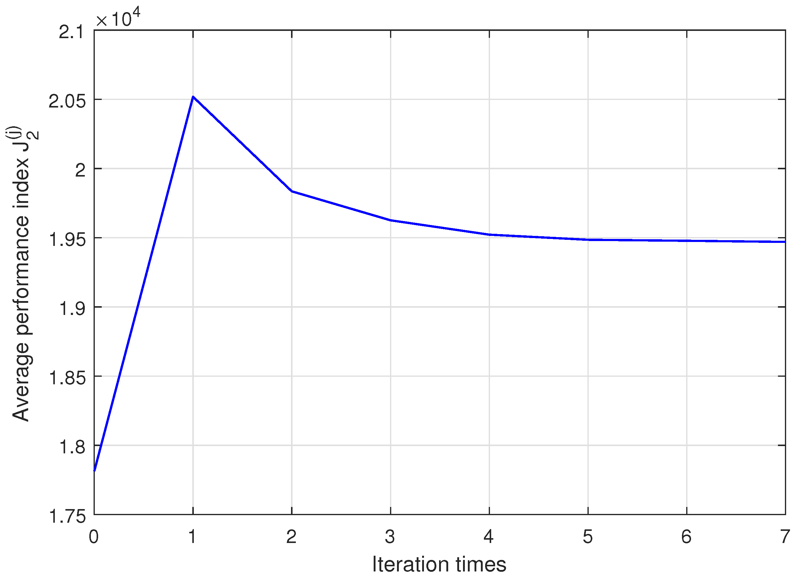
3.2. Computation of NES-Based Near-Optimal Controllers

Note from (39) and (40) that the optimal control law u * ( t ) is the sum of infinite series. Consequently, it is impossible to obtain its analytic value. In this situation, by taking finite terms of the series, a near-optimal control law can be obtained. For this, for a given positive integer , denote
g ( ) ( t ) = j = 0 g ˜ ( j ) ( t ) j ! , u ( ) ( t ) = j = 0 u ˜ ( j ) ( t ) j !
Then, one yields
g ( j ) ( t ) = g ( j 1 ) ( t ) + g ˜ ( j ) ( t ) j ! u ( j ) ( t ) = u ( j 1 ) ( t ) + u ˜ ( j ) ( t ) j ! , j = 1 , 2 , ,
which provide iterative formulae to compute near-optimal control law u ( ) ( t ) . Correspondingly, under the control of u ( ) ( t ) , the closed-loop system of the offshore structure is in the form as
z ˙ ( ) ( t ) = A z ( ) ( t ) + B u ( ) ( t ) + H f ( z ( ) ( t ) ) + D w ( t ) , z ( ) ( 0 ) = z 0
and the system performance index of the -th iteration is given as
J ( ) : = J ( u ( ) ( t ) ) = 1 2 ( z ( ) ( t f ) ) T Q f z ( ) ( t f ) + 1 2 0 t f ( z ( ) ( t ) ) T Q z ( ) ( t ) + r ( u ( ) ( t ) ) 2 d t
which can be utilized to compute the stopping criterion for the iterations.
Now, Algorithm 1 to compute the near-optimal control law is presented as follows.
Algorithm 1: An iterative algorithm.
Step 1. Given a small enough number ϵ > 0 . Set j = 0 and ϑ ( 0 ) = J ( 0 ) .
Step 2. Solve Equations (27) and (32) to obtain X 1 ( t ) and X 2 ( t ) , respectively.
Step 3. Solve Equations (29) and (28) to obtain the initial iteration values of z ˜ ( 0 ) ( t ) and u ˜ ( 0 ) ( t ) , set u ( 0 ) ( t ) = u ˜ ( 0 ) ( t ) , g ( 0 ) ( t ) = g 0 . Then compute z ( 0 ) ( t ) by (48) and J ( 0 ) by (49), respectively.
Step 4. Let j : = j + 1 , and solve Equations (35), (38) and (34) to obtain the j-th iterative values of z ˜ ( j ) ( t ) , g ˜ ( j ) ( t ) , and u ˜ ( j ) ( t ) , respectively.
Step 5. Solve (47) to obtain u ( j ) ( t ) and g ( j ) ( t ) . Then compute z ( j ) ( t ) by (48) and J ( j ) by (49), respectively.
Step 6. Compute ϑ ( j ) : = | J ( j ) J ( j 1 ) J ( j ) | . If ϑ ( j ) > ϵ , then go to Step 4; If ϑ ( j ) ϵ , the j-th iteration values of u ( j ) ( t ) and z ( j ) ( t ) are near-optimal control law and near-optimal state, respectively, and then complete the iteration.

4. Simulation Results

In this section, a nonlinear energy sink (NES)-based near-optimal controller is designed. Then, the controller is applied to offshore structures with regular waves and irregular waves, respectively, to show the effectiveness of the proposed control scheme. Moreover, the NES-based controller is compared with the TMD-based optimal controller to show the superiority of the proposed scheme.

4.1. Parameters of Offshore Structure with the NES

In Figure 1, the equivalent diameter of the structure D ˜ = 3.66 m, the structure length L = 249 m, the drag coefficient C d = 1.4, and the inertia coefficient C m = 2, the sea water density ρ = 1024 kg·m 3 . The parameters of the offshore structure with the NES are set as m 1 = 7,825,307 kg, c 1 = 641,150.15 N·s·m 1 , k 1 = 328,32,059.81 N·m 3 , and m 2 = 391,270 kg [34]. By optimizing the two parameters of c 2 and k 2 of the NES, in this paper, let c 2 = 400,000 N·s·m 1 and k 2 = 10,250,000 N·m 3 . Then one obtains the matrices A , B , D and H of (3) as
A = 0 1 0 0 4.1956 0.1330 0 0.0511 0 0 0 1 0 1.0223 0 1.0223 B = 10 6 × 0 0.128 0 2.556 T D = 10 7 × 0 1.278 0 0 T H = 0 1.3099 0 26.1967 T
The stiffness k t , damping c t , and mass of a TMD are set as k t = 1,489,000 N·m 3 , c t = 204,000 N·s·m 1 , and m t = 391,270 kg, respectively. The system parameters A ¯ , B ¯ and D ¯ of the offshore structure with the TMD in (42) are given as
A ¯ = 0 1 0 0 4.3859 0.1080 0.1903 0.0261 0 0 0 1 3.8056 0.5214 3.8056 0.5214 B ¯ = 10 5 × 0 0.0128 0 0.2556 T D ¯ = 10 6 × 0 0.1278 0 0.2556 T

4.2. Simulation of Regular and Irregular Wave Force

The significant wave hight H s =10 m, the water depth d = 218 m, and the JONSWAP spectrum is presented in Figure 2.
In what follows, for the regular wave and irregular wave, NES–based optimal controllers are designed, and the controlled performance of the structure is investigated respectively.
To obtain the regular wave force, set m = 1 in (12), and choose the peak frequency ω 0 = 0.6283 Hz. In this case, one yields the values M and N in (15) as
M = 0 1 0.3948 0 , N = 10 4 × 2.5082 0
The wave force on the structure is depicted in Figure 3. To yield irregular wave force, set m = 6 in (12). Then the matrices G and Π in (13) can be obtained as
G = G 1 G 2 , Π = 8.2635 × 10 5
where
G 1 = diag { 0.4329 , 1.7317 , 3.8964 } G 2 = diag { 6.9269 , 10.8232 , 15.5855 }
Further, by (15), one can obtain the irregular wave force, which is presented in Figure 4.

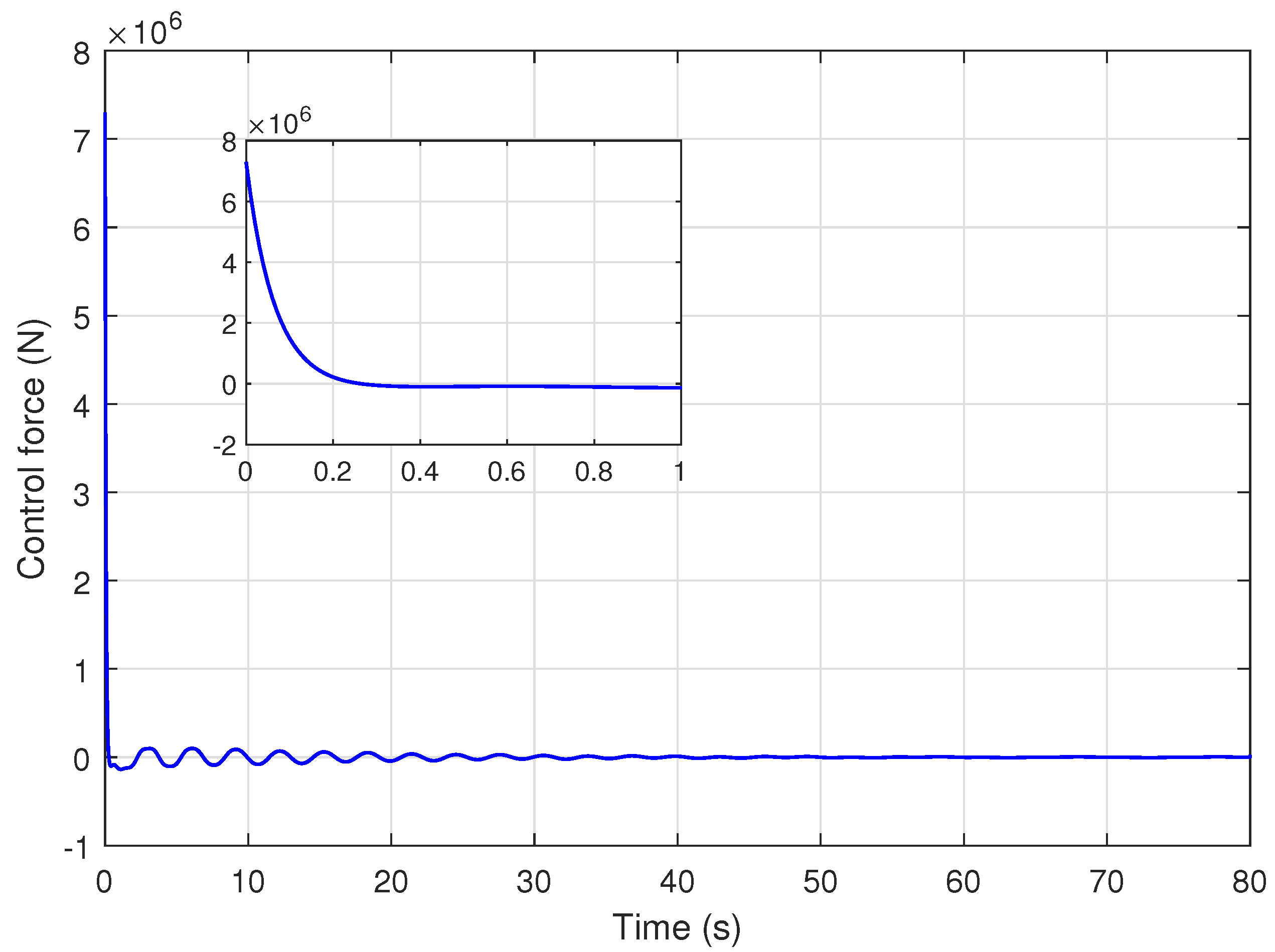
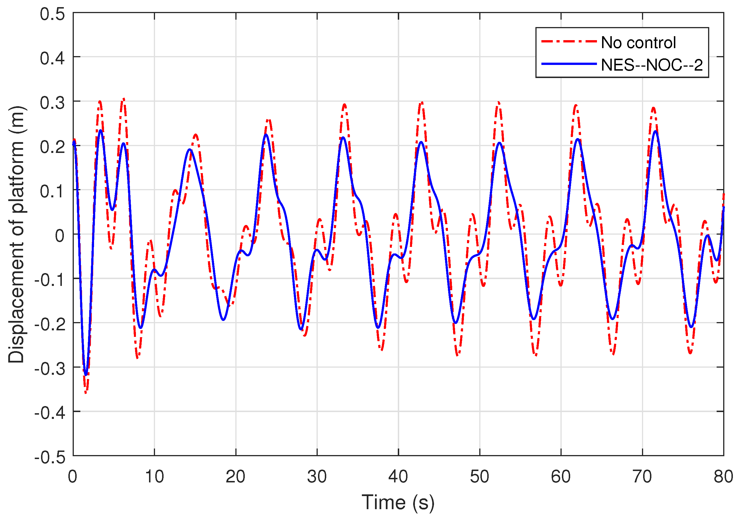
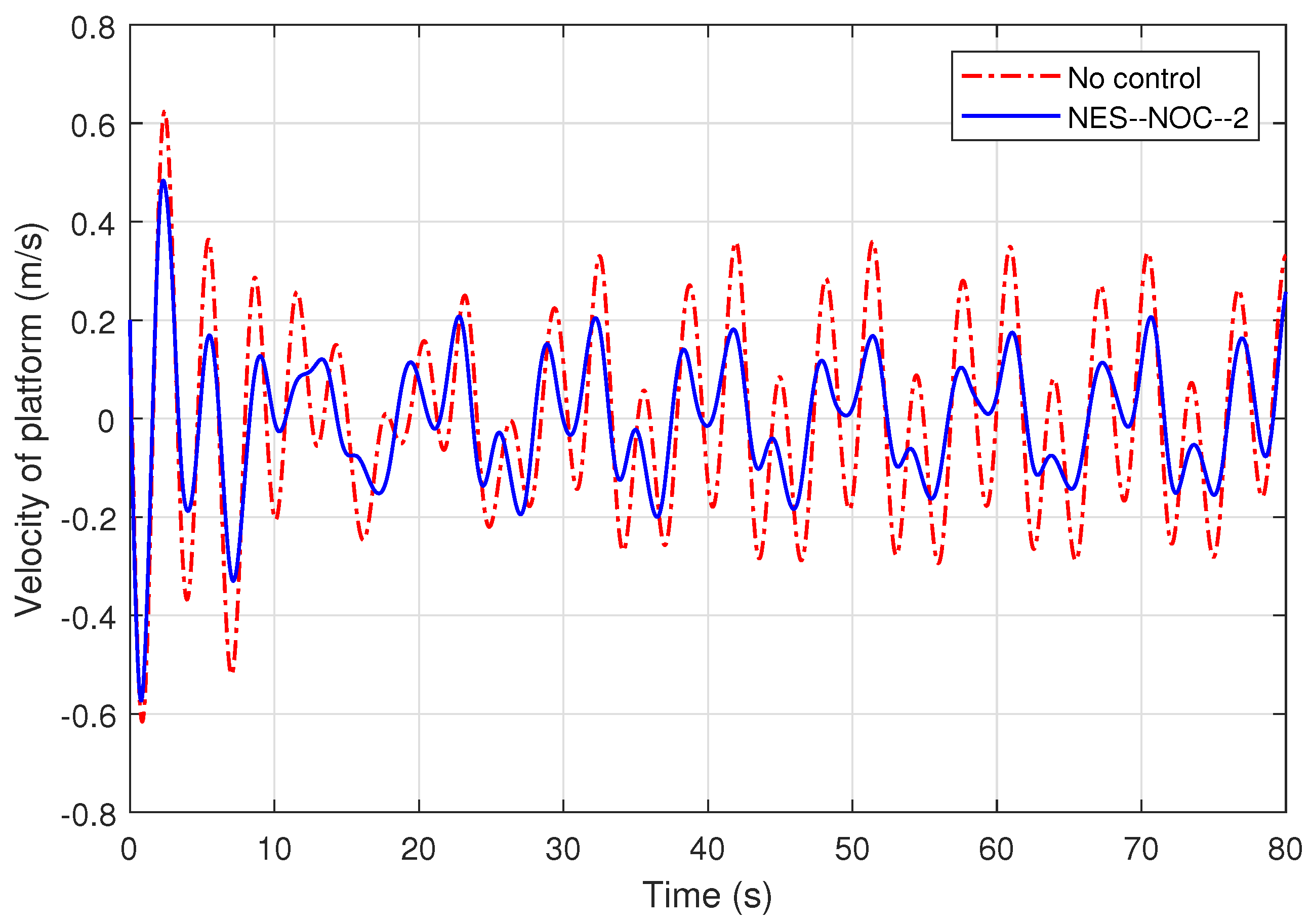
4.3. Performance of Structure with NES-Based Near-Optimal Controllers

The weight matrices Q f , Q, and r in (16) are set as
Q f = Q = 10 7 × diag { 5 , 2 , , 5 , 1 } , r = 5 × 10 7
and the initial state of the offshore structure is set as z 0 = 0.2 0.2 0.2 0.2 T .
Set the error bound ϵ = 0.0005 . By Proposition 1 and the iterative algorithm, one can obtain the NES–based near–optimal controllers (NOC). It is computed that after 7 iterations, one yields the near–optimal controller u ( 7 ) satisfying given error bound. Note that the designed optimal controllers depend on the wave–related matrices M and N. The designed NES–based near-optimal controllers are denoted u 1 ( j ) for regular wave case and u 2 ( j ) for irregular wave case, j = 0 , 1 , 2 , , 7 . Correspondingly, the system average performance index values of different iteration times under u 1 ( j ) and u 2 ( j ) are represented by J 1 ( j ) and J 2 ( j ) , which are listed in Table 1, and the curves of J 1 ( j ) and J 2 ( j ) versus j are depicted in Figure 5 and Figure 6, respectively.
To show the effectiveness of the proposed NES-based near-optimal controllers, denote u 1 ( 7 ) and u 2 ( 7 ) by NES–NOC–1 and NES–NOC–2, respectively. As the two controllers are respectively applied to the offshore structure subject to regular waves and irregular waves, the displacement and velocity response curves of the offshore structure and the control force are shown in Figure 7, Figure 8, Figure 9, Figure 10, Figure 11 and Figure 12, where the displacement and velocity of the offshore structure without controller are also depicted. The figures show that under the proposed controllers, the displacement and velocity of the structure are attenuated significantly.

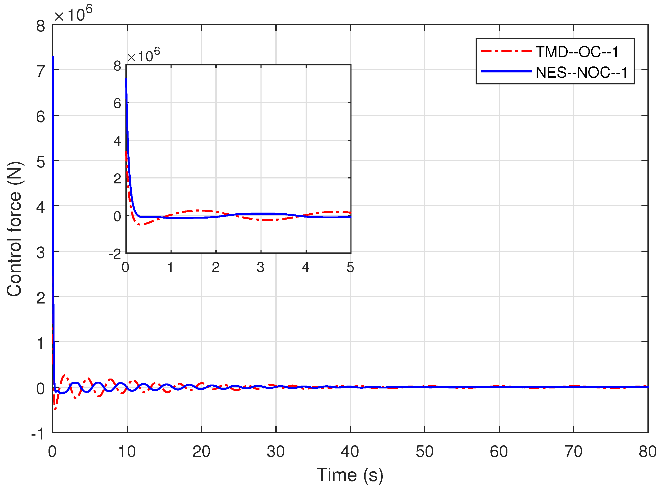
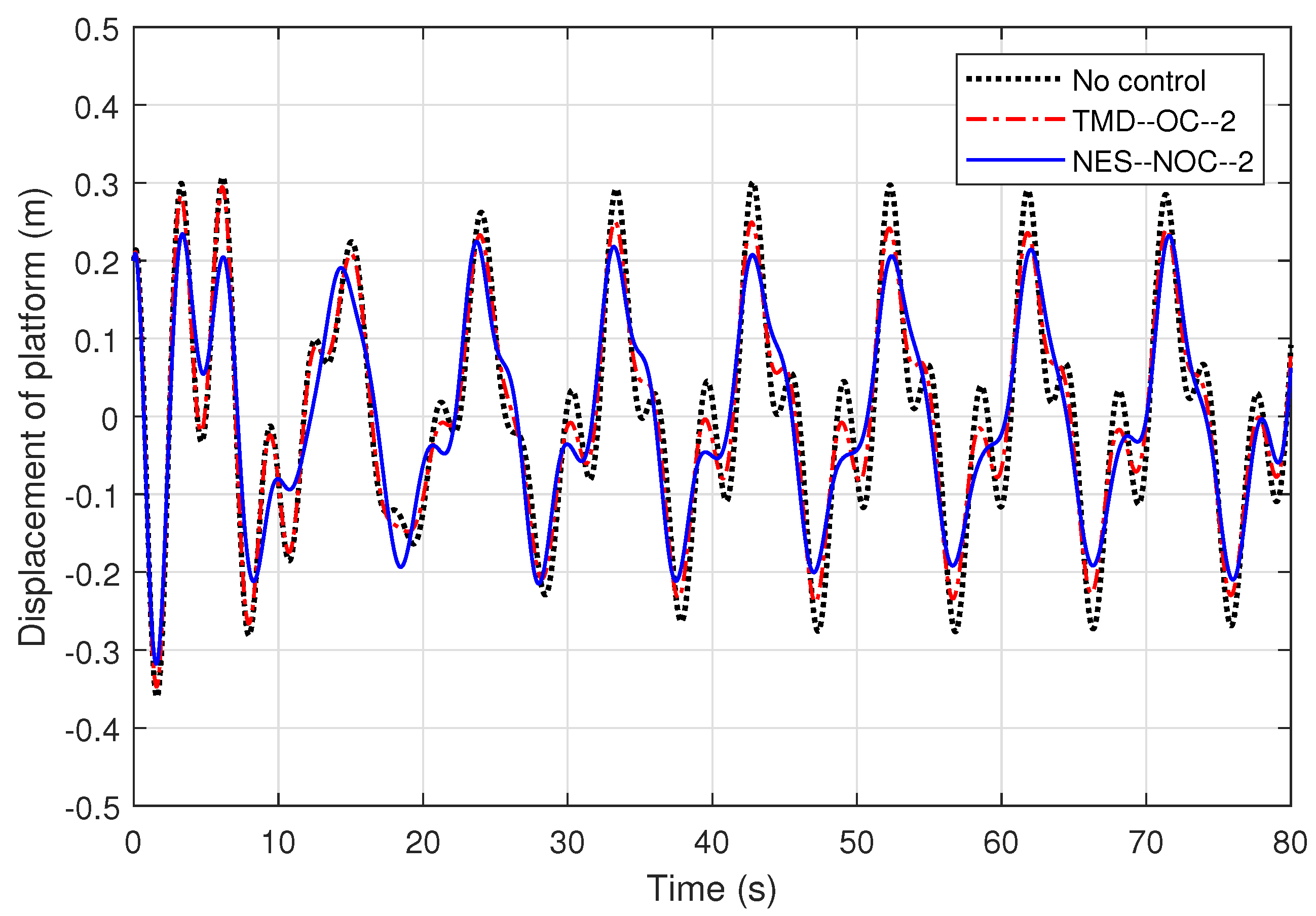
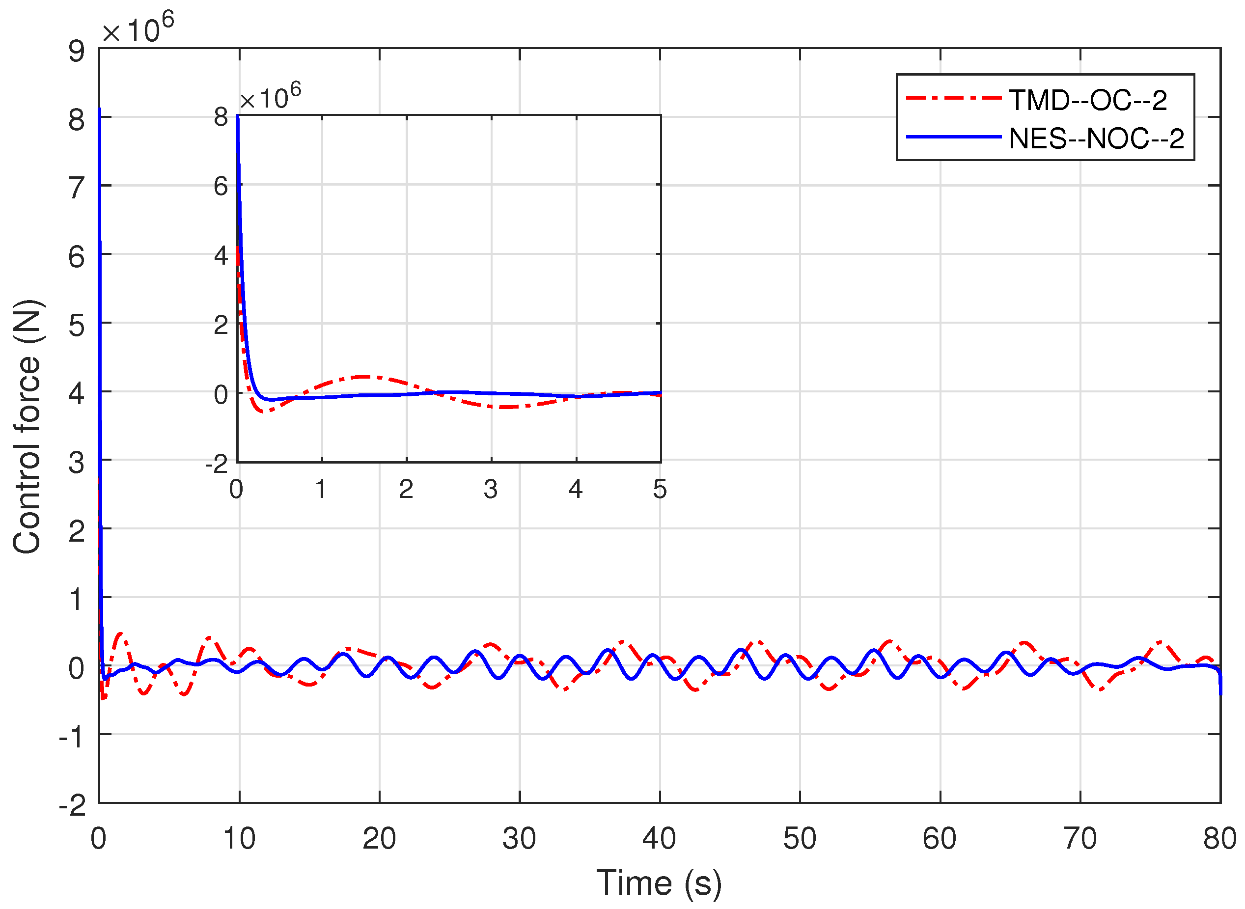
4.4. Comparisons between NES-Based Near-Optimal Controller and TMD-Based Optimal Controller

To demonstrate the superiority of the NES-based control over the linear TMD–based control, in this subsection, a TMD–based optimal controller is designed for the aforementioned offshore structure, which is equipped with an active TMD instead of the NES. The weight matrices Q f , Q and R are set same values as the ones of the NES–based controller.
Solving differential Equations (44) and (45) yields the matrices Y 1 ( t ) and Y 2 ( t ) , respectively. Then, one yields TMD–based optimal controllers in the form (43). The obtained controllers are denoted by TMD–OC–1 for the structure subject to regular waves and by TMD–OC–2 for the system subject to irregular waves. When the TMD–OC–1 and TMD–OC–2 are utilized the offshore structure subject to regular waves and the structure subject to irregular waves, the displacement and velocity responses of the offshore structure are presented by Figure 13, Figure 14, Figure 15, Figure 16, Figure 17 and Figure 18, respectively. In these Figures, the curves of the control force, the displacement and velocity of the structure without control and with NES–based controllers are also provided. Figure 13, Figure 14, Figure 15, Figure 16, Figure 17 and Figure 18 show that TMD-based optimal controllers can remarkably attenuate the wave-induced displacement and velocity responses of the structure. However, compared with the NES–based near optimal controllers and the TMD–based ones, the former is better than the latter. In fact, the structure under the NES-based optimal controllers presents better transient performance as well as steady-state performance than that under the TMD–based optimal controllers. Moreover, the average control cost of the former is smaller than that of the latter. In a word, the NES–based near-optimal controllers outperform the TMD–based optimal controllers from the point of view of the performance of the structure and the control cost.

5. Conclusions

The optimal control based vibration suppression issue of the offshore structure equipped with a nonlinear energy sink (NES) has been addressed in this paper. By introducing an active NES mechanism to the damping control system of the offshore structure, a nonlinear system model of the offshore structure has been established. By using the parameter perturbation approach, the optimal controller in the form of infinite series sum has been presented, and an iteration algorithm has been developed to compute the near–optimal controller for the offshore structure. Simulation results have shown that based on the NES, the performance of the marine structure with the designed near–optimal controller has been improved significantly. In fact, the key findings can be summarized as follows:
  • The active NES mechanism can be used to attenuate the vibration of the offshore structure. Based on the NES mechanism, the designed optimal controller can reduce the displacement and velocity of the structure remarkably.
  • Compared with the tuned mass damper (TMD) mechanism, the NES-based near-optimal controllers are better than the TMD-based optimal controllers to improve the performance of the offshore structure.
Notice that in the nonlinear dynamic model of the offshore structure considered in this paper, only the first dominant vibration mode is considered, while other vibration modes are ignored. Furthermore, only the wave force is taken into account, while other external disturbances on the structure are not considered. In addition, the parametric perturbation and saturation issues of actuator are not taken into account. Therefore, there still exist certain limitations of the vibration system modelling and controller design of the offshore structure. In the future, related investigations regarding more general NES-based dynamic models and effective active control schemes for the offshore structure can be carried out continuously.

Author Contributions

The conception, methodology and design were carried out by W.C. and B.-L.Z. The preparation, software and the first draft of the manuscript were written by X.D. and the draft was reviewed and edited by B.-L.Z. Material preparation, analysis, and validation were performed by Z.C. and Z.Z. All authors have read and agreed to the published version of the manuscript.

Funding

This work was supported in part by the Key Project of Natural Science Foundation of Zhejiang Province of China under Grant LZ19F030001 and the National Natural Science Foundation of China under Grants 61773356 and 51809245.

Institutional Review Board Statement

Not applicable.

Informed Consent Statement

Not applicable.

Data Availability Statement

The authors confirm that the data supporting the findings of this study are freely available upon request.

Conflicts of Interest

The authors declare that they have no conflict of interest.

References

  1. Zribi, M.; Almutairi, N.; Abdel-Rohman, M.; Terro, M. Nonlinear and robust control schemes for offshore steel jacket platforms. Nonlinear Dyn. 2004, 35, 61–80. [Google Scholar] [CrossRef]
  2. Qiao, D.; Li, B.; Yan, J.; Qin, Y.; Liang, H.; Ning, D. Transient responses evaluation of FPSO with different failure scenarios of mooring lines. J. Mar. Sci. Eng. 2021, 9, 103. [Google Scholar] [CrossRef]
  3. Feng, H.-N.; Zhang, B.-L.; Li, Q.; Tang, G.-Y. Delayed fuzzy output feedback H control for offshore structures. J. Mar. Sci. Eng. 2020, 8, 434. [Google Scholar] [CrossRef]
  4. Li, B. Operability study of walk-to-work for floating wind turbine and service operation vessel in the time domain. Ocean Eng. 2021, 220, 108397. [Google Scholar] [CrossRef]
  5. Kazemy, A. Robust mixed H/passive vibration control of offshore steel jacket platforms with structured uncertainty. Ocean Eng. 2017, 139, 95–102. [Google Scholar] [CrossRef]
  6. Ma, H.; Tang, G.-Y.; Hu, W. Feedforward and feedback optimal control with memory for offshore platforms under irregular wave forces. J. Sound Vib. 2009, 328, 369–381. [Google Scholar] [CrossRef]
  7. Sakthivel, R.; Santra, S.; Kaviarasan, B.; Park, J.H. Finite-time sampled-data control of permanent magnet synchronous motor systems. Nonlinear Dyn. 2016, 86, 2081–2092. [Google Scholar] [CrossRef]
  8. Huang, S.; Cai, M.; Xiang, Z. Robust sampled-data H control for offshore platforms subject to irregular wave forces and actuator saturation. Nonlinear Dyn. 2017, 88, 2705–2721. [Google Scholar] [CrossRef]
  9. Zhang, X.-M.; Han, Q.-L.; Han, D. Effects of small time-delays on dynamic output feedback control of offshore steel jacket structures. J. Sound Vib. 2011, 330, 3883–3900. [Google Scholar] [CrossRef]
  10. Zhang, B.-L.; Han, Q.-L.; Zhang, X.-M.; Yu, X. Sliding mode control with mixed current and delayed states for offshore steel jacket platforms. IEEE Trans. Control Syst. Technol. 2014, 22, 1769–1783. [Google Scholar] [CrossRef]
  11. Zhang, B.-L.; Han, Q.-L.; Zhang, X.-M. Event-triggered H reliable control for offshore structures in network environments. J. Sound Vib. 2016, 368, 1–21. [Google Scholar] [CrossRef]
  12. Zhang, Y.; Ma, H.; Xu, J. Neural network-based fuzzy vibration controller for offshore platform with random time delay. Ocean Eng. 2021, 225, 108733. [Google Scholar] [CrossRef]
  13. Kandasamy, R.; Cui, F.; Townsend, N.; Foo, C.C.; Guo, J.; Shenoi, A.; Xiong, Y. A review of vibration control methods for marine offshore structures. Ocean Eng. 2016, 127, 279–297. [Google Scholar] [CrossRef]
  14. Zhang, B.-L.; Han, Q.-L.; Zhang, X.-M. Recent advances in vibration control of offshore platforms. Nonlinear Dyn. 2017, 89, 755–771. [Google Scholar] [CrossRef]
  15. Zhang, B.-L.; Han, Q.-L.; Zhang, X.-M.; Tang, G.-Y. Active Control of Offshore Steel Jacket Platforms, 1st ed.; Springer: Singapore, 2019. [Google Scholar]
  16. Zhang, B.-L.; Cao, E.-Z.; Cai, Z.; Su, H.; Tang, G.-Y. Event-triggered H control for networked spar-type floating production platforms with active tuned heave plate mechanisms and deception attacks. J. Franklin Inst. 2021, 358, 3554–3584. [Google Scholar] [CrossRef]
  17. Vakakis, A.F. Inducing passive nonlinear energy sinks in vibrating systems. J. Vib. Acoust. 2001, 123, 324–332. [Google Scholar] [CrossRef]
  18. Tripathi, A.; Grover, P.; Kalmar-Nagy, T. On optimal performance of nonlinear energy sinks in multiple-degree-of-freedom systems. J. Sound Vib. 2017, 388, 272–297. [Google Scholar] [CrossRef] [Green Version]
  19. Gomez, F.; Fermandois, G.A.; Spencer, B.F. Optimal design of nonlinear energy sinks for mitigation of seismic response on structural systems. Eng. Struct. 2021, 232, 111756. [Google Scholar] [CrossRef]
  20. Tsiatas, G.C.; Charalampakis, A.E.; Tsopelas, P. A comparative study of linear and nonlinear mass damping systems under seismic excitation. Eng. Struct. 2020, 219, 110926. [Google Scholar] [CrossRef]
  21. Zhao, G.; Raze, G.; Paknejad, A.; Deraemaeker, A.; Kerschen, G.; Collette, C. Active nonlinear energy sink using force feedback under transient regime. Nonlinear Dyn. 2020, 102, 1319–1336. [Google Scholar] [CrossRef]
  22. Dekemele, K.; De Keyser, R.; Loccufier, M. Performance measures for targeted energy transfer and resonance capture cascading in nonlinear energy sinks. Nonlinear Dyn. 2018, 93, 259–284. [Google Scholar] [CrossRef]
  23. Dekemele, K.; Van Torre, P.; Loccufier, M. Design, construction and experimental performance of a nonlinear energy sink in mitigating multi-modal vibrations. J. Sound Vib. 2020, 473, 115243. [Google Scholar] [CrossRef]
  24. Tsiatas, G.C.; Charalampakis, A.E. A new hysteretic nonlinear energy sink. Commun. Nonlinear Sci. Numer. Simul. 2018, 60, 1–11. [Google Scholar] [CrossRef] [Green Version]
  25. Habib, G.; Romeo, R. The tuned bistable nonlinear energy sink. Nonlinear Dyn. 2017, 89, 179–196. [Google Scholar] [CrossRef]
  26. Zang, J.; Yuan, T.C.; Lu, Z.Q.; Zhang, Y.W.; Ding, H.; Chen, L.Q. A lever-type nonlinear energy sink. J. Sound Vib. 2018, 437, 119–134. [Google Scholar] [CrossRef]
  27. Sun, Y.H.; Zhang, Y.W.; Ding, H.; Chen, L.Q. Nonlinear energy sink for a flywheel system vibration reduction. J. Sound Vib. 2018, 429, 305–324. [Google Scholar] [CrossRef]
  28. Zhao, X.Y.; Zhang, Y.W.; Ding, H.; Chen, L.Q. Vibration suppression of a nonlinear fluid-conveying pipe under harmonic foundation displacement excitation via nonlinear energy sink. Int. J. Appl. Mech. 2019, 10, 1850096. [Google Scholar] [CrossRef]
  29. Pacheco, D.R.Q.; Marques, F.D.; Ferreira, A.J.M. Panel flutter suppression with nonlinear energy sinks: Numerical modeling and analysis. Int. J. Non-Linear Mech. 2018, 106, 108–114. [Google Scholar] [CrossRef]
  30. Jiang, X.; McFarland, D.M.; Bergman, L.A.; Vakakis, A.F. Steady state passive nonlinear energy pumping in coupled oscillators: Theoretical and experimental results. Nonlinear Dyn. 2003, 33, 87–102. [Google Scholar] [CrossRef]
  31. Zhang, Z.; Ding, H.; Zhang, Y.-W.; Chen, L.-Q. Vibration suppression of an elastic beam with boundary inerter-enhanced nonlinear energy sinks. Acta Mech. Sin. Lixue Xuebao 2021, 37, 387–401. [Google Scholar] [CrossRef]
  32. Zuo, H.; Zhu, S. Development of novel track nonlinear energy sinks for seismic performance improvement of offshore wind turbine towers. Mech. Syst. Signal Process. 2022, 172, 108975. [Google Scholar] [CrossRef]
  33. Zuo, H.; Zhang, J.; Yuan, G.-K.; Zhu, S. Wind- and sea wave-induced response mitigations of offshore wind turbines using track nonlinear energy sinks. Struct. Control Health Monit. 2022. in Press. [Google Scholar] [CrossRef]
  34. Zheng, Z.Q.; Yao, Z.P.; Chang, Z.Y. Vibration control of jacket offshore platform under random waveload based on nonlinear energy sink. Period. Ocean. Univ. China 2021, 51, 103–110. (In Chinese) [Google Scholar]
  35. Tang, G.-Y.; Sun, H.; Pang, H. Approximately optimal tracking control for discrete time-delay systems with disturbances. Prog. Nat. Sci. 2008, 18, 225–231. [Google Scholar] [CrossRef]
  36. Li, H.J.; James Hu, S.L.; Jakubiak, C. H2 active vibration control for offshore platform subjected to wave loading. J. Sound Vib. 2003, 263, 709–724. [Google Scholar] [CrossRef]
Figure 1. An NES-based offshore structure.
Jmse 10 00817 g001
Figure 2. The JONSWAP spectrum.
Jmse 10 00817 g002
Figure 3. The regular wave force on the structure.
Jmse 10 00817 g003
Figure 4. The irregular wave force on the structure.
Jmse 10 00817 g004
Figure 5. Performance index values of structure with u 1 ( j ) ( t ) .
Jmse 10 00817 g005
Figure 6. Performance index values of structure with u 2 ( j ) ( t ) .
Jmse 10 00817 g006
Figure 7. Displacements of the structure with NES–NOC–1.
Jmse 10 00817 g007
Figure 8. Velocities of the structure with NES–NOC–1.
Jmse 10 00817 g008
Figure 9. Control force by NES–NOC–1.
Jmse 10 00817 g009
Figure 10. Displacements of the structure with NES–NOC–2.
Jmse 10 00817 g010
Figure 11. Velocities of the structure with NES–NOC–2.
Jmse 10 00817 g011
Figure 12. Control force by NES-NOC-2.
Jmse 10 00817 g012
Figure 13. Displacements of the structure without control, with TMD–OC–1 and NES–NOC–1.
Jmse 10 00817 g013
Figure 14. Velocities of the structure without control, with TMD–OC–1 and NES–NOC–1.
Jmse 10 00817 g014
Figure 15. Control force by TMD–OC–1 and NES–NOC–1.
Jmse 10 00817 g015
Figure 16. Displacements of the structure without control, with TMD–OC–2 and NES–NOC–2.
Jmse 10 00817 g016
Figure 17. Velocities of the structure without control, with TMD–OC–2 and NES–NOC–2.
Jmse 10 00817 g017
Figure 18. Control force by TMD–OC–2 and NES–NOC–2.
Jmse 10 00817 g018
Table 1. System performance index values J 1 ( j ) and J 2 ( j ) for different iteration times j.
j01234567
J 1 ( j ) 3138.95745.74939.84709.54594.64553.54545.54535.5
J 2 ( j ) 17,81320,51919,835196,2619,5221948519,47819,470
Publisher’s Note: MDPI stays neutral with regard to jurisdictional claims in published maps and institutional affiliations.

