Article

A Novel Wellbore-Wall Heating Method without External Energy Injection for Natural Gas Hydrate Production—A Heat Transfer Device

1
College of Civil Engineering, Fuzhou University, Fuzhou 350108, China
2
School of Storage, Transportation and Construction Engineering, China University of Petroleum, Qingdao 266590, China
3
Graduate School of Engineering, Nagasaki University, Nagasaki 852-8521, Japan
*
Author to whom correspondence should be addressed.
J. Mar. Sci. Eng. 2022, 10(6), 799; https://doi.org/10.3390/jmse10060799
Submission received: 13 May 2022 / Revised: 3 June 2022 / Accepted: 5 June 2022 / Published: 10 June 2022

Abstract

:
Natural gas hydrate (NGH) dissociation is a heat-absorbing process, and the cooling around the wellhead is more pronounced during depressurization production. Low temperature will cause NGH regeneration or ice formation, blocking gas flow paths and reducing extraction efficiency. In this study, a novel heat transfer device (HTD) was innovatively proposed to alleviate this problem. Theoretical analysis and numerical simulations were used to research the methodological principles, applicable conditions, and expected benefits of the HTD. Results show that the HTD utilizes the characteristics of the geothermal gradient to rapidly transfer energy from the lower reservoir to the wellbore wall, which in turn raises the temperature and prevents the ice and NGH regeneration causing the blockage from adhering to the wellbore wall. The heat transfer radius, the length of the endothermic section, and the operating temperature difference make a tremendous difference in the heat transfer efficiency of the HTD. The HTD may be more suitable for Class 1 reservoir conditions and help to improve gas production under the depressurization method in the Shenhu sea of the South China Sea. The device can achieve continuous self-heat transfer without external energy injection to significantly reduce costs, which provides a new idea for marine NGH production.

1. Introduction

Natural gas hydrate (NGH) is stable at high pressure and low-temperature conditions, most of which exist in marine sediments where salts and sea mud are involved [1,2]. Water and methane gas molecules can form NGH in a specific range of temperatures and pressures after the gas migrates upward through sediment pores or fractures to the NGH stability zone [3,4]. The global estimates of methane gas trapped in NGH range widely between 1015 and 1018 STm3, with a total carbon content equivalent to twice the proven available fossil fuel resources [5,6,7]. Currently, gas recovery from the NGH reservoir is accomplished mainly by first dissolving the NGH in sediments into methane and water, then collecting the gas through the production well. The main production methods include depressurization, thermal stimulation, inhibitor injection, and CO2 displacement [8], which are widely applicable in trial tests. The depressurization method is the least expensive and most likely to be developed commercially today [9], which has been widely applied in four marine NGH production tests. In 2013 and 2017, Japan implemented offshore NGH production in the Nankai Trough two times by depressurization in a vertical well, with the highest average gas production of about 19,833 m3/day [10,11]. In 2017 and 2020, a single vertical well and a single horizontal well were used to successfully implement short-term depressurization test production of marine NGH in the Shenhu sea area of the South China Sea, with the highest average gas production of about 28,713 m3/day [12,13]. Thus far, there is still a certain distance from the threshold of commercial exploitation for all field trials [2]. In the process of depressurization production, the NGH dissociation requires a large amount of heat absorption, which in turn leads to a decrease in temperature and the Joule–Thomson (J–T) effect [14]. Around the wellbore, water may then freeze, and methane gas and water may also synthesize NGH again under low-temperature and high-pressure conditions, limiting productivity. On the one hand, ice and secondary NGH may reduce the reservoir’s effective porosity and permeability, negatively impacting the release of methane gas. On the other hand, they block openings in the wellbore wall, preventing methane gas and water from flowing into the wellbore.
Generally speaking, to solve the wellbore blockage problem, the depressurization method is usually combined with the thermal stimulation method to achieve the exploitation. The thermal stimulation method raises the NGH reservoir temperature above the phase equilibrium point mainly by injecting hot water or steam, whose main advantage is that the rate of NGH dissociation can be effectively controlled [15]. So far, it has been applied in practice in the Mackenzie Delta (Canada) and the Qilian Mountains permafrost zone (China) [16,17]. However, due to the poor heat transfer conditions of the NGH reservoir, simply increasing the heat source temperature or the heat injection will result in a large amount of heat lost [18]. Meanwhile, it is difficult to build and maintain heating equipment due to the storage conditions of NGH (permafrost or deep-sea). Thus, thermal stimulation alone fails to achieve high-efficiency production of NGH [19]. However, it offers significant advantages in applications where localized areas are exploited to avoid NGH regeneration or ice formation around the well, thus maintaining better seepage channels, which is manifested by heating the wellbore wall to fulfill the purpose of heat transfer.
In recent years, numerical simulations and experimental studies have been carried out mainly from thermal stimulation methods and efficiency viewpoints. Kurihara et al. studied depressurization combined with wellbore-wall heating by numerical simulation and found that the wellbore-wall heating may effectively promote NGH dissociation, but the corresponding energy efficiency is low [20]. The related conclusion was further confirmed by Loh et al. with an experiment in which increasing the wellbore wall temperature failed to increase the energy efficiency [21]. Despite the differences in wellbore structure or thermal stimulation methods used in different literature, they all involve geothermal application modes of direct heating by hot water/steam [18]. These methods will inevitably form a high-pressure area around the heat injection wellbores, which is not conducive to NGH dissociation.
Therefore, the non-fluid-assisted heating mode has also been extensively researched. Liang et al. showed that electric heating-assisted production increase was better than hot water heating under direct wellbore depressurization conditions [22]. Fasler et al. found that gas production with the assistance of electric heating increased by 3.8 times compared with gas production under the pure depressurization method through experiments [23]. Ning et al. proposed using renewable solar power to heat the extraction of marine hydrates, reducing the cost of energy use [24]. Zhao et al. found that microwave stimulation is more suitable for formations with high initial NGH saturation and more suitable for local heating [25]. Li et al. and Islam demonstrated that the dissociation efficiency of NGH due to microwave heating and electromagnetic heating is much higher than that of hot water injection heating conditions under the same thermal power conditions [26,27]. Liu et al. proposed a geothermal-assisted CO2 displacement method, in which CO2 is first injected into the geothermal reservoir for heating and subsequently returned to the NGH reservoir to promote NGH dissociation [28,29]. In conclusion, the non-fluid-assisted heating exploitation method overcomes the potential engineering geological risks of fluid heating and improves the efficiency of gas production [18]. However, transmitting energy through electric, microwave, electromagnetic wave, and radiofrequency to heat the wellbore wall consumes a large amount of energy if it is continuously turned on. Low-consumption measures such as renewable energy or geothermal heat may be an essential adjunct to future depressurization production.
In this work, a novel heat transfer device (HTD) was first proposed to avoid ice formation and NGH regeneration phenomena. The HTD can realize continuous self-heat transfer and conduct heat to the wellbore wall without external energy injection, significantly reducing the cost of use. First, the principle and conditions of application of the HTD were elaborated. Then, the improving mechanism of the HTD on depressurization production of marine NGH was analyzed, and the heat transfer power of the HTD was theoretically derived. Finally, the applicability of HTD-based wellbore-wall heating combined with the depressurization method in the Shenhu sea of the South China Sea was explored. The study aims to provide a new idea for preventing ice and NGH regeneration from clogging wellbore openings.

2. Method Description

2.1. Thermal Pipe Technology

In 1963, George Grover created a highly efficient heat transfer element [30], the heat pipe, which has attracted significant attention in the science community. The heat pipe uses the principle of thermal conductance and the rapid thermal transfer nature of the phase-change medium. It can transfer heat rapidly from a heated object to the outside of the heat source, whose thermal conductance capacity exceeds that of most metal. Thus, thermal pipes have been widely used in aerospace, metallurgy, petroleum, and chemical industries [31,32]. Its overall structure can usually be divided into the evaporation, adiabatic, and condensation sections (Figure 1a). The adiabatic section is wrapped with adiabatic material. The working medium changes into steam in the evaporation section by absorbing heat and condenses into a liquid state in the condensation section by releasing heat exotherm. The liquid working medium flows back to the evaporation section by the capillary force of the wick. Then, the evaporated steam diffuses to the condensation section under the pressure difference action so that the working medium can circulate in the thermal pipe, allowing the heat from the evaporation section to transfer to the condensation section.
The gravity heat pipe is one of the heat pipes, also known as a two-phase closed thermosyphon [33]. It creates medium reflux mainly by gravity, ignoring the complex capillary core structure, is less challenging to produce, and has lower production costs. The gravity heat pipe plays an essential role in solving the plateau permafrost problem due to the unidirectional thermal conductivity, meaning the heat can only be transferred from a lower to a higher positioned area [34]. The gravity heat pipe can bring the heat out of the ground, distribute it into the air in winter, and effectively stop the heat from passing downward in summer, which is an efficient heat-conducting device to control heat transfer. Figure 1b shows its operating mode during the cold season (top cold and bottom hot), and Figure 1c shows its dormant state during the hot season (top hot and bottom cold). In addition, the gravity heat pipe does not require external power and has no moving parts, no noise interference, and no daily maintenance. If these properties could be applied to NGH exploitation, it would be an economical, green, and efficient way of auxiliary heating.
Figure 1. The working principle of heat pipe [35,36]: (a) heat pipe structure; (b) heat pipe start (cold season); (c) heat pipe dormancy (hot season).
Jmse 10 00799 g001

2.2. Application in Wellbore-Wall Heating

During depressurization production, NGH dissociation absorbs heat, resulting in a decrease in reservoir temperature, which can instantaneously reduce the local sediment temperature by 33 °C [37]. Low reservoir temperature will reduce the NGH dissociation rate and may trigger NGH regeneration and block methane transport channels. In this study, based on the principles of the gravity heat pipe, a novel HTD attached to the wellbore wall was proposed to prevent ice and NGH regeneration from clogging wellbore openings. Several HTDs and fixtures form an annular fence net type, which is fixed inside/outside the suitable position of the drilling trap casing and enters the NGH reservoir together when drilling the wellbore (Figure 2). The HTD is a heat conduction pipe of gas-liquid two-phase flow circulation. It consists of a closed vacuum cavity injected with a working medium, relying on its internal working medium phase change to realize heat transfer. The HTD consists of a seamless steel tube and the liquid ammonia contained within, divided into the exothermic, connecting, and endotherm sections. The exothermic section is located in the NGH reservoir that needs energy replenishment, whereas the endotherm section is located in the high-temperature region. Liquid ammonia can boil and change into gaseous ammonia to absorb heat when it touches the high-temperature region in the endotherm section. Then, the gaseous ammonia moves upward, condenses and releases heat in the exothermic section, and changes back into liquid to flow back to the lower part. The HTD can continuously transfer heat to the low-temperature region in this cycle.
Figure 3 illustrates the vertical wellbore depressurization exploitation mode with HTD assistance. The entire production process is as follows: (i) the drilling trap casing and HTD are installed together into the NGH reservoir when drilling and placing the casing; (ii) after the drilling is completed, the completion fluid is injected to fill the void around the drilling trap casing and then forms the annular fence mesh-type package together; (iii) the wellbore starts to execute depressurized production, and the temperature around the wellbore wall attachment drops sharply due to heat absorption by the NGH dissociation; and (vi) the HTD starts to activate under the ground temperature gradient, which transfers heat from the lower part of the extraction area to the transport wellbore wall by the internal phase change of the working medium. Theoretically, the HTD has the advantages of high thermal conductivity, no external power source, and no daily maintenance, which achieves low-cost utilization of subsea heat to prevent NGH regeneration and ice formation from clogging the wellbore. However, more than the conventional vertical wellbore length into the reservoir (typically 1/2 to 2/3 of the reservoir thickness), the HTD requires that the bottom of the wellbore be drilled to reach the free gas layer or the underlying layer to meet the conditions required for temperature differentials. This process will undoubtedly increase the difficulty and risk of the project. Nevertheless, in the current marine trial cases, the drilling depths have reached over 200 m. The HTD only needs to drill tens of meters more than the original one, with specific engineering feasibility. The applicability of the HTD to different NGH reservoirs will be discussed in detail in Section 3.3.

3. Heat Transfer Efficiency Analysis

3.1. Reaction Heat of Hydrate Dissociation

The essential principle of NGH dissociation or formation is to use specific physical and chemical means to decompose the in situ NGH into gas-water in two phases (Figure 4). The basic NGH dissociation formula is given as follows:
C H 4 n H 2 O ( s o l i d ) C H 4 ( g a s ) + n H 2 O ( l i q u i d / i c e ) Δ r H m = + 52 ~ 54.49 kJ / mol
The dissociation of NGH into methane and water is a heat-absorbing reaction, and the dissociation of NGH requires 52~54.49 kJ/mol of heat absorption, depending on the crystal type [38]. Therefore, only specific measures are required to heat the wellbore wall or reservoir around the wellbore to prevent ice formation and NGH regeneration from plugging the wellbore.

3.2. Heat Transfer Control Formula

The heat transfer capacity of the HTD is its total heat transfer during coupling with the reservoir, which is related to the heat transfer area of the HTD, reservoir temperature, reservoir temperature difference, and other factors.
{ Ω ( S , α , Δ T , t ) = α × S × Δ T ( t ) Δ T > 0 Ω ( S , α , Δ T , t ) = 0 Δ T > 0
where Ω is heat transfer capacity; α is convective heat transfer coefficient; ΔT is the temperature difference of the NGH reservoir, °C; and t is time, s.
The HTD, like other heat pipes, is affected by the thermal resistance of different parts in the heat transfer process and exhibits different heat transfer efficiency, so it is also necessary to consider the thermal resistance when calculating the heat transfer. The total heat production Q in unit time t can be expressed as follows:
Q = T s ( t ) T a ( t ) R f ( t ) + R s ( t ) + R c w ( t ) d t
where Q is total heat transfer, J; Ts is the temperature of the endotherm section, °C; Ta is the temperature of the exothermic section, °C; Rf is the condenser thermal resistance, °C/W; Rs is the reservoir thermal resistance, °C/W; and Rcw is the HTD internal thermal resistance, °C/W.
The Rf is a function of various factors, such as exothermic section condenser shape, size, surface temperature, gas/liquid flow rate, etc. It is usually determined experimentally and is also referred to using the following formula:
R f = 1 A h α
where Ah is the heating surface area of the condenser, m2.
The Rs describes the diffusion capacity of heat in the NGH reservoir, which is related to the thermal conductivity of the NGH reservoir concerning the endotherm section diameter. Assuming that the heat-absorbing section of the hot rod is an infinitely long linear heat transfer body, the analytical solution of Rs can be obtained by using the cylindrical thermal resistance formula.
R s = ln ( 2 r d ) 2 π λ z
where d is the HTD diameter, m; λ is the average thermal conductivity of the reservoir, W/m/K; z is the length of the endotherm section, m; and r is the HTD heat transfer radius, which can be found by Fourier’s second law as follows:
r = k r λ t π C ln ( A 0 A r )
where kr is the correction coefficient; A0 is the temperature range of the sidewall, °C; Ar is the temperature range of r, °C; and C is volumetric heat capacity, J/m3/K.
The Rcw is mainly composed of tube wall thermal resistance (Rw), condensate film thermal resistance (Rc), phase change thermal resistance (Rp), and flow thermal resistance (Rt). Usually, the Rw, Rc, Rp, and Rt are of the order 10−4~10−8 °C/W. However, the Rf and Rs are of the order 10−1~10−2 °C/W, which are much larger than RCW. In the actual calculation, ignoring other thermal resistance, only Rf and Rs are used for analysis (Figure 5), and the accuracy is fully satisfied for engineering applications.

3.3. Reservoir Condition

For most marine reservoirs, there is a top-down difference in ground temperature. As the temperature of the upper core exploitation area decreases, it will intensify the temperature difference between the exothermic section and endotherm section, which can fully utilize the effectiveness of the HTD. In addition, since the HTD mainly relies on the internal working medium for heat transfer and its primary purpose is to heat the wellbore wall, the thermal conductivity sensitivity to water, rock, and NGH is low. Thus, it can be used in any NGH reservoir suitable for the depressurization method.
The temperature difference between the two ends of the HTD plays a crucial role in its efficacy. The distribution of temperature characteristics varies for different NGH reservoir types during the exploitation process. Based on the type of sediment in the NGH bearing layer (NBL), NGH content, and the trap structure of the strata, Moridis et al. revealed four main classes of the NGH reservoirs in nature [39] (Figure 6):
(1)
First category. The NBL, with an underlying two-phase fluid layer including free gas and water, makes up the Class 1 reservoir. Methane gas can be recovered directly before NGH dissociation in the Class 1 reservoir, which has excellent gas production potential to achieve commercial production, with distribution areas such as the Messoyakha gas field in Russia [40], North Slope tundra in the USA [20], Mallik area in Canada [16], the Black Sea in Turkey [41], and northern land slope of the South China Sea [42];
(2)
Second category. The NBL and underlying mobile water constitute the Class 2 reservoir. It is easy to carry out depressurization production in distribution areas like the Gulf of Mexico [43] and the Nankai Trough, Japan [44];
(3)
Third category. The NBL without underlying mobile water makes up the Class 3 reservoir. It is usually distributed in terrestrial areas, such as the Qilian Mountain tundra in China [45] and the Ulleung Basin in Korea [46];
(4)
Fourth category. Low saturation and dispersed hydrate reservoirs are classified as the Class 4 reservoir, which is challenging to recover gas from, without commercial exploitation value [47].
In summary, both Class 1 and Class 2 reservoirs contain high-saturation NGH, which are the most critical types of NGH resources in the world. However, the most critical working condition for the HTD is to have sufficient temperature difference at its upper and lower ends. In both reservoir classes, the exothermic section of the HTD is located in the NBL, where the temperature decreases sharply during depressurization production, as required. The endotherm section is located in the free gas layer (FGL) and the water layer (WL), where there is no NGH dissociation and the temperature remains relatively stable. The FGL can increase gas production even when the contribution of NGH dissociation is small, whereas the WL may intensify the water flow and inhibit gas production. In addition, Merey and Sinayuc found that wellbore heating might help avoid NGH reformation near perforation intervals [41]. Thus, the Class 1 reservoir may be the best choice for meeting the working conditions of the HTD.

4. Application Example Analysis

In view of the difficulty and cost of in situ tests of marine NGH, numerical simulation techniques have been applied to study the long-term dissociation characteristics and exploitation patterns of NGH reservoirs under different production methods. This section established different cases referring to the relevant parameters of the first production in the South China Sea to (i) explore the variation of HTD heat transfer power, temperature, and NGH evolution of the wellbore wall under different production pressures and (ii) study the applicability of depressurization combined wellbore-wall heating exploitation in NGH reservoirs in the Shenhu sea.

4.1. Model Construction

4.1.1. Geological Model

In 2017 and 2020, China carried out the first and second trial production of NGH in the Shenhu sea of the South China Sea, where the Shenhu reservoir is considered one of the most promising deposits of NGH [17]. Since the HTD is used in conjunction with vertical wellbores, station W17, where the first exploitation took place, was used as the basis for the numerical model. The NGH reservoir at station W17 is a Class 1 reservoir, which can be subdivided into the NBL from 201 to 236 m below the seafloor, the mixing layer (ML), with fissures being filled with solid NHG, free gas, and liquid water, from 236 to 251 m below the seafloor, and the FGL, from 251 to 278 m below the seafloor. The porosity of the NBL, the ML, and the FGL are 35%, 33%, and 32%, respectively, and their mean average permeability are 2.9 mD, 1.5 mD, and 7.4 mD, respectively. The NGH saturation of the NBL and the ML is 31.0% and 11.7%, and the gas saturation of ML and the FGL is 13.2% and 7.3% [12,48]. The specific parameters are shown in Table 1.
Figure 7 shows the cylinder model, divided into overburden layer (OL), NBL, MX, FGL, and underlying layer (UL) from top to bottom, corresponding to thicknesses of 30 m, 36 m, 15 m, 27 m, and 30 m, respectively. Benefitting from the symmetry of the cylinder model, only a quarter of the NGH reservoir was used for simulation. The cylinder model has a grid size (Δz) of 10 m along the z-direction for the OL and UL, and Δz is 3 m for NBL, ML, and FGL. The outer boundary was extended to R = 250 m to minimize the boundary effect as much as possible. The boundary conditions assume no heat flux or mass movement in the lateral direction. At the same time, the top of the OL and the bottom of the UL are held at a constant temperature to supply heat flux into the reservoir from the adjacent strata. Furthermore, to accurately portray the NGH dissociation process, the simulation approach considers NGH regeneration and ice formation during synthesis.

4.1.2. Numerical Simulator Code

CMG STARS was used in this study for the numerical simulations in wellbore-wall heating. The code uses a kinetic reaction model [49] and considers stress field response characteristics when performing NGH exploitation, which is widely used in the numerical simulation of NGH communities [50]. The model considered the following conditions: (i) three phases (gas phase, liquid phase, and solid phase) and three components (dissociation gas component, liquid component, and NGH component) were considered, where NGH was treated as a solid phase existing in porous media in the form of spherical particles; (ii) the reservoir was considered to be homogeneous, including porosity and permeability, etc. (iii) the diffusion of methane gas and its dissolution in water during production was neglected; and (iv) the heat conduction, heat convection, and endothermic NGH dissociation were considered [8].
The sediment pore capillary pressure was calculated using the Van Genuchten formula [51].
P c = P c o [ ( S * ) 1 δ 1 ] 1 δ
S * = S w S w r 1 S w r S g r
where Pc is the capillary force, N; Pco is the capillary force endpoint value, N; δ is the Van Genuchten parameter; Sw is water saturation; Swr is the residual water saturation; and Sgr is the residual gas saturation.
During the NGH dissociation process, the ice produced will change the effective porosity due to the heat-absorbing by NGH. Furthermore, the changes in effective porosity will affect the value of the effective permeability using the Kozeny–Carman formula [52].
ϕ = ϕ o ( 1 S i )
k = k o ( ϕ ϕ o ) ε [ ( 1 ϕ o ) ( 1 ϕ ) ] 2
where ϕo is the initial porosity; Si is the ice saturation; k is the permeability, mD; ko is the initial permeability, mD; and ε is the experience index.

4.1.3. Production Method and Case Design

The depressurization method is considered the most cost-effective method for NGH exploitation, allowing the continuous promotion of gas production rate as the effective permeability of the NGH reservoir increases due to the NGH dissociation [9]. However, with the current increased strength and stiffness of the wellbore and the emergence of steel construction devices [53], the magnitude of depressurization has further expanded, which exacerbates the problem of NGH regeneration and ice production. Therefore, in this study, the HTD-assisted heat transfer was used with the depressurization method to produce methane gas. First, the average temperature difference between the NBL and FGL was extracted from the literature of the simulated area, and the ΔT value interval of the HTD was calculated according to the local temperature difference of 33 °C proposed by Cranganu [37]. Then, the heat transfer power of the HTD in different cases was calculated by substituting the relevant parameters into Formula (3). Finally, the effect of the combined depressurized wellbore-wall heating method was evaluated by CMG STARS.
As shown in Figure 7, the vertical well is located in the center of the model and is distributed along the z-direction, covering the entire NGH reservoir. The length of the wellbore opening section covers the NBL. The HTD (exothermic section 36 m, connecting section 15 m, evaporation section 27 m) is equidistant around the inner surface of the wellbore wall. To calculate the heat transfer power of the HTD, in the model, the outer diameter of the HTD is 0.02 m, the outer diameter of the wellbore is 0.3 m, the production pressures are 2 MPa and 4 MPa, the production period is 500 days, and the production method is a one-time depressurization.
The heat transfer power of a single HTD can be obtained by substituting the relevant parameters into Formula (3) (Figure 8). The temperature difference in the NGH reservoir (ΔT) on the heat transfer power (q) is a linear increase. The larger the ΔT, the better the heat transfer performance of the HTD. The increase of the heat transfer radius (r) fails to strengthen the q, which may be due to the increased heat loss by extensive heat transfer. In contrast, the enhancement in the length of the evaporation section (z) can increase q, especially at larger ΔT. This is because the larger z allows more heat in the reservoir to be absorbed simultaneously. However, an increase in z inevitably leads to an enlargement in thermal resistance, which slows down the promotion in q. Overall, the heat transfer limit of a single HTD is about 1200 W, which fails to meet the demand for wellbore-wall heating. In practice, the number of HTDs used can be considered to increase q, although the total power inevitably needs to be discounted as the number increases. In order to explore the variation of gas production and temperature evolution of wellbore walls under different production pressure, 8 cases were established (Table 2).

4.2. Numerical Simulation Results

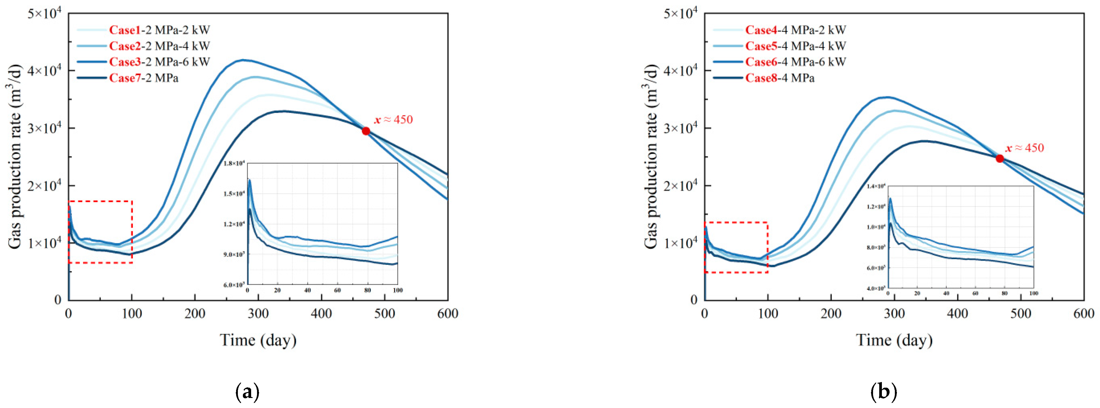
4.2.1. Gas Production

Figure 9 shows the methane gas production rates of various cases with different heat transfer powers (2, 4, 6 kW) and production pressures (2, 4 MPa). The gas production rate increases with the promotion of heat transfer power. Case three and six with the heat transfer power of 6 kW are at the highest level before 450 days, although they remain low and far less than the commercial production criterion. Also, comparing Figure 9a,b, it can be found that the gas production effects under the three different wellbore-wall heating powers differ very little in the first 100 days, and the curves oscillate downwards. It indicates that the NGH dissociation at this stage mainly relies on depressurization drive, and ice formation and NGH regeneration appear. As exploitation progressed, the effect of heating began to make a difference, and the gas production curve started to rise. At the end of production, the NGH near the well is fully dissociated, but that portion of the heat generated by the wellbore-wall heating has a restricted range of influence and has little effect on the NGH dissociation farther away. Besides, limited by model size and boundary conditions, the curves begin to diverge after 450 days. In addition, Ruan et al. also confirm that the variation of gas production rate at different wellbore wall temperatures is slight, which can be almost negligible [54]. Consequently, the emphasis on heat injection temperature or heating power may not improve the energy efficiency ratio. The power provided by the HTD is limited but sufficient to achieve the goal of preventing clogging of the wellbore wall at a low cost.
Figure 10 further counts the cumulative gas production of each case. Although the gas production rate is high early on with HTD, when the gas production rate peaked, it is essentially the same for both production methods, and the final results do not differ as much as the experimental scale [23]. During the 600-day production cycle, the cumulative gas production of Cases one to three increased by 7.35%, 14.55%, and 20.09%, respectively, compared to Case seven at a production pressure of 2 MPa. Furthermore, at a production pressure of 4 MPa, the cumulative gas production of Cases four to six increased by 8.28%, 15.52%, and 21.19%, respectively, compared to Case eight. Overall, the wellbore-wall heating helps improve the NGH gas production in the depressurization mode, which is better than in the pure depressurization mode. Moreover, from the simulation results, the following references can be provided for actual production: (i) during the tried test period (100 d), the HTD plays a limited role due to the slight temperature difference between the two ends of the HTD; (ii) during the short-term production period (365 d), the HTD effectively avoids well wall blockage, allowing the pressure reduction method to continue efficiently; and (iii) the HTD fails to increase auxiliary depressurization production in the long-term period.

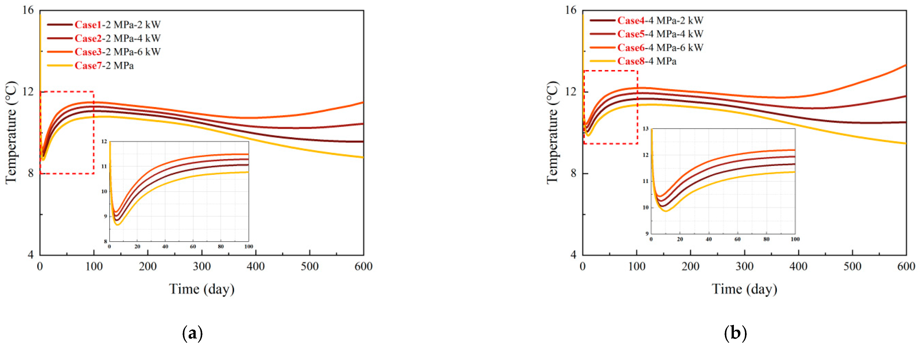
4.2.2. Temperature Evolution

Figure 11 shows the temperature dependence on time at the location of the measurement points in the open-hole section of the wellbore for different extraction pressures of NGH, with two different ways of extraction: pressure reduction combined with wellbore-wall heating and simple pressure reduction. The temperature around the wellbore drops rapidly due to a combined effect of massive NGH dissociation and J–T cooling. As the temperature difference between the upper and lower ends continues to increase, heat from below the reservoir begins to transfer to the open-hole section, causing the temperature to rise back up to some extent. Immediately afterward, the region around the wellbore begins to warm up due to the warmer water from the OL and UL flowing into the well. Then, many NGHs around the well dissociate into methane gas and water flowing into the production well, which is heat-absorbing and causes the temperature to decrease again slowly. Finally, the NGH around the well dissociates out, and the temperature of Cases one to six increases again under the action of heat transfer, whereas in Cases seven to eight it continues to decrease. In general, wellbore-wall heating in production wells can provide heat to the area and raise the temperature effectively, but at the same time, its scope and effectiveness are minimal. This may be due to (i) the heat transfer area and thermal conductivity associated with the wellbore wall, which would increase if replaced with a steel wellbore or device, and (ii) the much lower heat transfer power of the HTD than the rewarming effect from the hot water/steam injection.

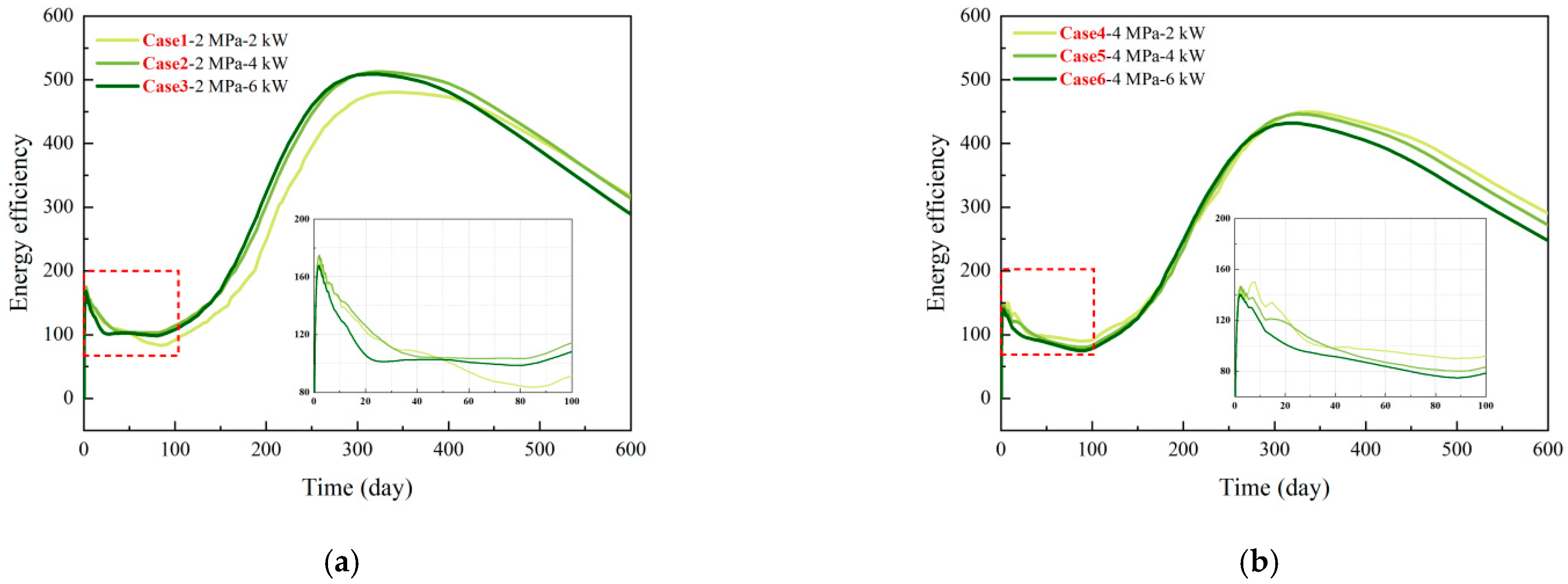
4.2.3. Energy Efficiency

Energy efficiency is an essential metric of concern for all thermal stimulation methods, which can intuitively reflect the relationship between the heat input in NGH exploitation and the resulting additional methane gas production. In this work, energy efficiency is defined as the ratio of the calorific value (33,494.4 kJ/m3) for the additional produced methane gas (based on the pure depressurization method) to the heat input from the HTD. The relationship between energy efficiency and time is shown in Figure 12. In general, the curves follow roughly the same trend as that of the gas production rate, with a change in trend at around 100 d and 300 d. Cases one to three reveal that higher heat transfer power can improve energy efficiency in the short term, with the most pronounced change especially at 2 kW to 4 kW. However, at higher production pressures, such as Cases four to six, the effect of different heat transfer powers on the energy efficiency is more negligible, which indicates that the degree of wellbore plugging is related to the production pressure, i.e., the higher the production pressure, the less NGH regeneration and ice formation will occur. Regardless of the type of thermal stimulation, the emphasis on heat injection temperature or heating power may not improve energy efficiency. Therefore, it is unnecessary to “over-dose” the heat source as an auxiliary tool in the depressurization method to assist thermal stimulation production; instead, the maximum energy efficiency ratio for heat injection or heating parameters should be used as the preferable criterion [18].
The energy efficiency of HTD is highly satisfactory, mainly because its idea of assisted depressurization is different from the conventional thermal stimulation method. The heat transfer method of the HTD is designed to solve the wellbore plugging problem and thus take full advantage of the depressurization method so that only the proper heat input is required and that heat does not need to be input manually. The latter is mainly done by injecting large amounts of hot water/steam, which solves the wellbore plugging problem and sufficiently raises the temperature of the reservoir around the wellbore. Although it can enhance methane gas production, its energy loss is enormous. This type of thermal stimulation method is proposed to solve more of a long-term production problem. However, in terms of the current production cycle of marine trial production (6~60 d), achieving a short-term production capacity increase and adopting appropriate measures to mitigate wellbore plugging and the sanding problem may be the urgent issues to be addressed. The HTD may provide a new way of thinking to solve these problems.

5. Conclusions

A novel HTD was first proposed to prevent ice and NGH regeneration from clogging wellbore openings in this study. To reveal the effect of this new device, the principles of the HTD, heat transfer formulas, and application cases were analyzed and explored. The following conclusions were obtained:
(1)
The HTD is a heat conduction pipe of gas-liquid two-phase flow circulation, attached circumferentially to the inside or outside of the wellbore wall. It can transfer heat from the lower part of the NGH reservoir to the open-hole section of the wellbore without external energy injection by using the temperature difference between the upper and lower ends during the pressure-reducing production process.
(2)
The ΔT on the q is a linear increase. The increase of the r fails to strengthen the q due to the increased heat loss by extensive heat transfer. The enhancement in the z can increase q, especially at larger ΔT. However, an increase in z inevitably leads to an enlargement in thermal resistance, slowing down the promotion in q.
(3)
The HTD can be used in any NGH reservoir suitable for the depressurization method. The FGL for a Class 1 reservoir can increase gas production even when the contribution of NGH dissociation is small and will not intensify the water flow and inhibit gas production. Thus, it may be the best choice for meeting the working conditions of the HTD.
(4)
The power provided by the HTD is limited but sufficient to achieve the goal of preventing clogging of the wellbore wall at a low cost. In addition, wellbore-wall heating helps to improve gas production under the depressurization method, which is better than the pure depressurization exploitation scenario. However, from the simulation results, HTD may be more suitable for production in the short term (365 d).
(5)
Wellbore-wall heating in production wells can provide heat to the area and raise the temperature effectively. However, at the same time, its scope and effectiveness are minimal because of the low power of the HTD and the low thermal conductivity of the production well.
(6)
The energy efficiency of HTD is highly satisfactory because its heat transfer technique is designed to address the wellbore clogging problem. It can entirely take advantage of the depressurization method, requiring only the proper heat input, and eliminate the need for manual heat input.

Author Contributions

Conceptualization, H.Y. and X.W.; methodology, X.W.; software, D.L.; validation, X.W.; formal analysis, G.G.; investigation, H.Y.; resources, X.W.; data curation, H.Y.; writing—original draft preparation, H.Y.; writing—review and editing, X.W.; visualization, H.Y.; supervision, X.W.; project administration, X.W.; funding acquisition, X.W. and Y.J. All authors have read and agreed to the published version of the manuscript.

Funding

This study has been partially funded by the Natural Science Foundation of China (41907251, 52179098), the Natural Science Foundation of Shandong Province (ZR2019ZD14), and the Natural Science Foundation of Fujian Province (2019J05030).

Institutional Review Board Statement

Not applicable.

Informed Consent Statement

Not applicable.

Data Availability Statement

Not applicable.

Conflicts of Interest

The authors declare no conflict of interest.

References

  1. Zeng, H.; Zhang, Y.; Zhang, L.; Chen, Z.; Li, X. Effects of the NaCl Concentration and Montmorillonite Content on Formation Kinetics of Methane Hydrate. J. Mar. Sci. Eng. 2022, 10, 548. [Google Scholar] [CrossRef]
  2. Sloan, E.D. Fundamental principles and applications of natural gas hydrates. Nature 2003, 426, 353–359. [Google Scholar] [CrossRef] [PubMed]
  3. Li, C.; Zhan, L.; Lu, H. Mechanisms for Overpressure Development in Marine Sediments. J. Mar. Sci. Eng. 2022, 10, 490. [Google Scholar] [CrossRef]
  4. Kida, M.; Suzuki, K.; Kawamura, T.; Oyama, H.; Nagao, J.; Ebinuma, T.; Narita, H.; Suzuki, H.; Sakagami, H.; Takahashi, N. Characteristics of natural gas hydrates occurring in pore-spaces of marine sediments collected from the eastern Nankai trough, off Japan. Energy Fuels 2009, 23, 5580–5586. [Google Scholar] [CrossRef]
  5. Zhang, P.; Tian, S.; Zhang, Y.; Li, G.; Zhang, W.; Khan, W.A.; Ma, L. Numerical simulation of gas recovery from natural gas hydrate using multi-branch wells: A three-dimensional model. Energy 2021, 220, 119549. [Google Scholar] [CrossRef]
  6. Koh, C.A.; Sloan, E.D.; Sum, A.K.; Wu, D.T. Fundamentals and applications of gas hydrates. Annu. Rev. Chem. Biomol. Eng. 2011, 2, 237–257. [Google Scholar] [CrossRef]
  7. Kvenvolden, K.A. Methane hydrate—A major reservoir of carbon in the shallow geosphere? Chem. Geol. 1988, 71, 41–51. [Google Scholar] [CrossRef]
  8. Ye, H.; Wu, X.; Li, D. Numerical simulation of natural gas hydrate exploitation in complex structure wells: Productivity improvement analysis. Mathematics 2021, 9, 2184. [Google Scholar] [CrossRef]
  9. Aghajari, H.; Moghaddam, M.H.; Zallaghi, M. Study of effective parameters for enhancement of methane gas production from natural gas hydrate reservoirs. Green Energy Environ. 2019, 4, 453–469. [Google Scholar] [CrossRef]
  10. Yamamoto, K.; Wang, X.X.; Tamaki, M.; Suzuki, K. The second offshore production of methane hydrate in the Nankai Trough and gas production behavior from a heterogeneous methane hydrate reservoir. RSC Adv. 2019, 9, 25987–26013. [Google Scholar] [CrossRef] [Green Version]
  11. Yamamoto, K.; Terao, Y.; Fujii, T.; Ikawa, T.; Seki, M.; Matsuzawa, M.; Kanno, T. Operational overview of the first offshore production test of methane hydrates in the Eastern Nankai Trough. In Proceedings of the Offshore Technology Conference, Houston, TX, USA, 5–8 May 2014; Volume 3, pp. 1802–1812. [Google Scholar] [CrossRef]
  12. Li, J.F.; Ye, J.L.; Qin, X.W.; Qiu, H.J.; Wu, N.Y.; Lu, H.L.; Xie, W.W.; Lu, J.A.; Peng, F.; Xu, Z.Q.; et al. The first offshore natural gas hydrate production test in South China Sea. China Geol. 2018, 1, 5–16. [Google Scholar] [CrossRef]
  13. Ye, J.L.; Qin, X.W.; Xie, W.W.; Lu, H.L.; Ma, B.J.; Qiu, H.J.; Liang, J.Q.; Lu, J.A.; Kuang, Z.G.; Lu, C.; et al. The second natural gas hydrate production test in the South China Sea. China Geol. 2020, 3, 197–209. [Google Scholar] [CrossRef]
  14. Oldenburg, C.M. Joule-Thomson cooling due to CO2 injection into natural gas reservoirs. Energy Convers. Manag. 2007, 48, 1808–1815. [Google Scholar] [CrossRef] [Green Version]
  15. Liu, B.; Yuan, Q.; Su, K.H.; Yang, X.; Wu, B.C.; Sun, C.Y.; Chen, G.J. Experimental simulation of the exploitation of natural gas hydrate. Energies 2012, 5, 466–493. [Google Scholar] [CrossRef]
  16. Moridis, G.J.; Collett, T.S.; Dallimore, S.R.; Satoh, T.; Hancock, S.; Weatherill, B. Numerical studies of gas production from several CH4 hydrate zones at the Mallik site, Mackenzie Delta, Canada. J. Pet. Sci. Eng. 2004, 43, 219–238. [Google Scholar] [CrossRef] [Green Version]
  17. Zhu, Y.; Wang, P.; Pang, S.; Zhang, S.; Xiao, R. A Review of the Resource and Test Production of Natural Gas Hydrates in China. Energy Fuels 2021, 35, 9137–9150. [Google Scholar] [CrossRef]
  18. Wu, N.; Li, Y.; Wan, Y.; Sun, J.; Huang, L.; Mao, P. Prospect of marine natural gas hydrate stimulation theory and technology system. Nat. Gas Ind. 2020, 40, 100–115. [Google Scholar] [CrossRef]
  19. Collett, T.S. Gas hydrate production testing—Knowledge gained. In Proceedings of the Offshore Technology Conference, Houston, TX, USA, 6–9 May 2019. [Google Scholar] [CrossRef]
  20. Kurihara, M.; Sato, A.; Funatsu, K.; Ouchi, H.; Masuda, Y.; Narita, H.; Collett, T.S. Analysis of formation pressure test results in the Mount Elbert methane hydrate reservoir through numerical simulation. Mar. Pet. Geol. 2011, 28, 502–516. [Google Scholar] [CrossRef]
  21. Loh, M.; Too, J.L.; Falser, S.; Linga, P.; Khoo, B.C.; Palmer, A. Gas production from methane hydrates in a dual wellbore system. Energy Fuels 2015, 29, 35–42. [Google Scholar] [CrossRef]
  22. Liang, Y.P.; Liu, S.; Wan, Q.C.; Li, B.; Liu, H.; Han, X. Comparison and optimization of methane hydrate production process using different methods in a single verticalwell. Energies 2019, 12, 124. [Google Scholar] [CrossRef] [Green Version]
  23. Falser, S.; Uchida, S.; Palmer, A.C.; Soga, K.; Tan, T.S. Increased gas production from hydrates by combining depressurization with heating of the wellbore. Energy Fuels 2012, 26, 6259–6267. [Google Scholar] [CrossRef]
  24. Ning, F.; Wu, N.; Jiang, G.; Zhang, L.; Guan, J.; Yu, Y.; Tang, F. A method to use solar energy for the production of gas from marine hydrate-bearing sediments: A case study on the Shenhu Area. Energies 2010, 3, 1861–1879. [Google Scholar] [CrossRef] [Green Version]
  25. Zhao, J.; Fan, Z.; Wang, B.; Dong, H.; Liu, Y.; Song, Y. Simulation of microwave stimulation for the production of gas from methane hydrate sediment. Appl. Energy 2016, 168, 25–37. [Google Scholar] [CrossRef]
  26. Li, D.L.; Liang, D.Q.; Fan, S.S.; Li, X.S.; Tang, L.G.; Huang, N.S. In situ hydrate dissociation using microwave heating: Preliminary study. Energy Convers. Manag. 2008, 49, 2207–2213. [Google Scholar] [CrossRef]
  27. Islam, M.R. A new recovery technique for gas production from Alaskan gas hydrates. J. Pet. Sci. Eng. 1994, 11, 267–281. [Google Scholar] [CrossRef]
  28. Liu, Y.; Hou, J.; Zhao, H.; Liu, X.; Xia, Z. A method to recover natural gas hydrates with geothermal energy conveyed by CO2. Energy 2018, 144, 265–278. [Google Scholar] [CrossRef]
  29. Liu, Y.; Hou, J.; Chen, Z.; Su, H.; Zhao, E.; Li, G. A novel natural gas hydrate recovery approach by delivering geothermal energy through dumpflooding. Energy Convers. Manag. 2020, 209, 112623. [Google Scholar] [CrossRef]
  30. Grover, G.; Cotter, T.; Erickson, G. Erratum: Structures of very high thermal conductance. J. Appl. Phys. 1964, 35, 3072. [Google Scholar] [CrossRef]
  31. Yue, C.; Zhang, Q.; Zhai, Z.; Wang, J.; Ling, L. Numerical study on flow and thermal characteristics of a micro-channel separated heat pipe under various surface wettability. Case Stud. Therm. Eng. 2021, 28, 101345. [Google Scholar] [CrossRef]
  32. Wang, Y.; Liu, Y.; Cui, Y.; Guo, W.; Lv, J. Numerical simulation of soil freezing and associated pipe deformation in ground heat exchangers. Geothermics 2018, 74, 112–120. [Google Scholar] [CrossRef]
  33. Nikolaenko, Y.E.; Pekur, D.V.; Sorokin, V.M.; Kravets, V.Y.; Melnyk, R.S.; Lipnitskyi, L.V.; Solomakha, A.S. Experimental study on characteristics of gravity heat pipe with threaded evaporator. Therm. Sci. Eng. Prog. 2021, 26, 101107. [Google Scholar] [CrossRef]
  34. Cen, J.; Li, F.; Li, T.; Huang, W.; Chen, J.; Jiang, F. Experimental study of the heat-transfer performance of an extra-long gravity-assisted heat pipe aiming at geothermal heat exploitation. Sustainability 2021, 13, 12481. [Google Scholar] [CrossRef]
  35. Shafieian, A.; Khiadani, M.; Nosrati, A. Strategies to improve the thermal performance of heat pipe solar collectors in solar systems: A review. Energy Convers. Manag. 2019, 183, 307–331. [Google Scholar] [CrossRef]
  36. Wang, E.L.; Tian, Y.; Liu, X.; Ren, Z.; Hu, S. Thermosyphon Application in the Embankment Project in Permafrost Area. J. Water Resour. Archit. Eng. 2021, 19, 148–153159. [Google Scholar] [CrossRef]
  37. Cranganu, C. In-situ thermal stimulation of gas hydrates. J. Pet. Sci. Eng. 2009, 65, 76–80. [Google Scholar] [CrossRef]
  38. Rydzy, M.B.; Schicks, J.M.; Naumann, R.; Erzinger, J. Dissociation enthalpies of synthesized multicomponent gas hydrates with respect to the guest composition and cage occupancy. J. Phys. Chem. B 2007, 111, 9539–9545. [Google Scholar] [CrossRef]
  39. Moridis, G.J.; Collett, T.S.; Boswell, R.; Kurihara, M.; Reagan, M.T.; Koh, C.; Sloan, E.D. Toward production from gas hydrates: Current status, assessment of resources, and simulation-based evaluation of technology and potential. SPE Reserv. Eval. Eng. 2009, 12, 745–771. [Google Scholar] [CrossRef] [Green Version]
  40. Makogon, Y.F.; Omelchenko, R.Y. Commercial gas production from Messoyakha deposit in hydrate conditions. J. Nat. Gas Sci. Eng. 2013, 11, 1–6. [Google Scholar] [CrossRef]
  41. Merey, S.; Sinayuc, C. Investigation of gas hydrate potential of the Black Sea and modelling of gas production from a hypothetical Class 1 methane hydrate reservoir in the Black Sea conditions. J. Nat. Gas Sci. Eng. 2016, 29, 66–79. [Google Scholar] [CrossRef]
  42. Ning, F.; Liang, J.; Wu, N.; Zhu, Y.; Wu, S.; Liu, C.; Wei, C.; Wang, D.; Zhang, Z.; Xu, M.; et al. Reservoir characteristics of natural gas hydrates in China. Nat. Gas Ind. 2020, 40, 1–24. [Google Scholar] [CrossRef]
  43. Klapp, S.A.; Murshed, M.M.; Pape, T.; Klein, H.; Bohrmann, G.; Brewer, P.G.; Kuhs, W.F. Mixed gas hydrate structures at the Chapopote Knoll, southern Gulf of Mexico. Earth Planet. Sci. Lett. 2010, 299, 207–217. [Google Scholar] [CrossRef]
  44. Fujii, T.; Suzuki, K.; Takayama, T.; Tamaki, M.; Komatsu, Y.; Konno, Y.; Yoneda, J.; Yamamoto, K.; Nagao, J. Geological setting and characterization of a methane hydrate reservoir distributed at the first offshore production test site on the Daini- Atsumi Knoll in the eastern Nankai Trough, Japan. Mar. Pet. Geol. 2014, 66, 310–322. [Google Scholar] [CrossRef]
  45. Li, X.S.; Yang, B.; Li, G.; Li, B. Numerical simulation of gas production from natural gas hydrate using a single horizontal well by depressurization in Qilian mountain permafrost. Ind. Eng. Chem. Res. 2012, 51, 4424–4432. [Google Scholar] [CrossRef]
  46. Ryu, B.-J.; Riedel, M. Gas hydrates in the Ulleung Basin, East Sea of Korea. Terr. Atmos. Ocean. Sci. 2017, 28, 943–963. [Google Scholar] [CrossRef] [Green Version]
  47. Le, A.N.; Huuse, M.; Redfern, J.; Gawthorpe, R.L.; Irving, D. Seismic characterization of a Bottom Simulating Reflection (BSR) and plumbing system of the Cameroon margin, offshore West Africa. Mar. Pet. Geol. 2015, 68, 629–647. [Google Scholar] [CrossRef]
  48. Sun, Y.; Ma, X.; Guo, W.; Jia, R.; Li, B. Numerical simulation of the short- and long-term production behavior of the first offshore gas hydrate production test in the South China Sea. J. Pet. Sci. Eng. 2019, 181, 106196. [Google Scholar] [CrossRef]
  49. Kim, H.C.; Bishnoi, P.R.; Heidemann, R.A.; Rizvi, S.S.H. Kinetics of methane hydrate decomposition. Chem. Eng. Sci. 1987, 42, 1645–1653. [Google Scholar] [CrossRef]
  50. Gaddipati, M. Code Comparison of Methane Hydrate Reservoir Simulators using CMG STARS Manohar. Master’s Thesis, West Virginia University, Morgantown, WV, USA, 2008. [Google Scholar]
  51. Genuchten, V.M. A closed-form equation for predicting the hydraulic conductivity of unsaturated soils. Soil Sci. Soc. Am. J. 1980, 44, 892–898. [Google Scholar] [CrossRef] [Green Version]
  52. Carman, P.C. Permeability of saturated sands, soils and clays. J. Agric. Sci. 1939, 29, 262–273. [Google Scholar] [CrossRef]
  53. Wu, X.; Ye, H.; Jiang, Y.; Li, D.; Wang, G. Development of a novel self-entry exploitation device for marine natural gas hydrate and the feasibility studies. Ocean Eng. 2022, 254, 111365. [Google Scholar] [CrossRef]
  54. Ruan, X.; Li, X.; Xu, C.; Zhang, Y.; Yan, K. Numerical simulation of gas production from hydrate by depressurization combined with well-wall heating. Huagong Xuebao/CIESC J. 2015, 66, 1544–1550. [Google Scholar] [CrossRef]
Figure 2. The connection between the HTD and the wellbore wall.
Jmse 10 00799 g002
Figure 3. Schematic of the HTD working in depressurization production.
Jmse 10 00799 g003
Figure 4. NGH three-phase balance curve [8].
Jmse 10 00799 g004
Figure 5. Heat transfer process of the HTD.
Jmse 10 00799 g005
Figure 6. The classification of hydrate reservoirs.
Jmse 10 00799 g006
Figure 7. Simplified numerical simulation system and the mesh distribution.
Jmse 10 00799 g007
Figure 8. The heat transfer efficiency of the HTD: (a) the relationship between q, r, and ΔT; (b) the relationship between q, z, and ΔT.
Jmse 10 00799 g008
Figure 9. Gas production characteristics: (a) production pressure of 2 MPa; (b) production pressure of 4 MPa.
Jmse 10 00799 g009
Figure 10. Cumulative gas production of different cases.
Jmse 10 00799 g010
Figure 11. Temperature evolution of the open-hole section of wellbore: (a) production pressure of 2 MPa; (b) production pressure of 4 MPa.
Jmse 10 00799 g011
Figure 12. Evolution of energy efficiency: (a) production pressure of 2 MPa; (b) production pressure of 4 MPa.
Jmse 10 00799 g012
Table 1. Numerical simulation model parameters for station W17 in Shenhu sea.
ParameterValueParameterValue
Thickness of OL and UL15 mInitial saturation of OL and ULSh = 0, Sw = 1, Sg = 0
Thickness of NBL36 mInitial saturation of NBLSh = 0.34, Sw = 0.66, Sg = 0
Thickness of ML15 mInitial saturation of MLSh = 0.31, Sw = 0.526, Sg = 0.164
Thickness of FGL27 mInitial saturation of FGLSh = 0, Sw = 0.922, Sg = 0.078
Porosity of OL and UL0.3NGH molar mass0.119543 kg/gmole
Porosity of NBL0.35NGH density919.7 kg/m3
Porosity of ML0.33Seawater density1020 kg/m3
Porosity of FGL0.32Thermal conductivity of rock2.7 W/m/K
Initial permeability of OL and ULkox = koy = 2 mD, koz = 1 mDThermal conductivity of water0.69 W/m/K
Initial permeability of NBLkox = koy = 2.9 mD, koz = 1.45 mDThermal conductivity of NGH0.5 W/m/K
Initial permeability of MLkox = koy = 1.5 mD, koz = 0.75 mDFormation temperatureT = 14.475 + 0.03z °C, z is the depth (m)
Initial permeability of FGLkox = koy = 7.4 mD, koz = 3.7 mDFormation pressureP = 1.469 + 0.01z MPa, z is the depth (m)
Table 2. Production parameters for different cases.
CaseProduction PressureHeat Transfer PowerProduction Method
Case 12 MPa2 kWDP + WH 1
Case 22 MPa4 kWDP + WH
Case 32 MPa6 kWDP + WH
Case 44 MPa2 kWDP + WH
Case 54 MPa4 kWDP + WH
Case 64 MPa6 kWDP + WH
Case 72 MPa/DP 2
Case 84 MPa/DP
1 Depressurization combined with wellbore-wall heating; 2 Pure depressurization.
Publisher’s Note: MDPI stays neutral with regard to jurisdictional claims in published maps and institutional affiliations.

