Article

Dumbbell-Shaped Damage Effect of Closed Cylindrical Shell Subjected to Far-Field Side-On Underwater Explosion Shock Wave

Institute of Defense Engineering, AMS, PLA, Beijing 100850, China
*
Authors to whom correspondence should be addressed.
J. Mar. Sci. Eng. 2022, 10(12), 1874; https://doi.org/10.3390/jmse10121874
Submission received: 25 October 2022 / Revised: 21 November 2022 / Accepted: 22 November 2022 / Published: 3 December 2022
(This article belongs to the Special Issue Failure Analysis of Marine Structure)

Abstract

:
In naval warfare, underwater explosion (UNDEX) shock waves significantly influence the stability and safety of the pressure hull structure of the equipment. This study investigated the unique dynamic buckling of a closed cylindrical shell subjected to a far-field side-on UNDEX shock wave using a three-dimensional numerical simulation based on acoustic–structural arithmetic. In particular, the flow-field response characteristics, plastic deformation, and yield characteristics of the cylindrical shell were determined under the influence of the UNDEX shock wave. Subsequently, the failure mode of the cylindrical shell was analyzed to propose the dumbbell-shaped damage effect. The results revealed that when the UNDEX shock wave encounters a finite cylindrical shell, the fluid exhibits a perturbation such as pressure division, stress wave deflection, and flow in the surroundings of the circular cylinder. However, the fluid cannot produce a sizeable instantaneous displacement that yields certain strong constraints at both ends of the cylindrical shell. These constraints generate an irregular distribution of the flow field pressure, and the cylindrical shell tends to exhibit an “arch” deformation along the direction of shock wave propagation. Owing to the flow surrounding the circular cylinder, a negative pressure zone is generated in the flow field at both ends of the cylindrical shell, which induces a “sucking disc” shape at both ends of the cylindrical shell and ultimately produces a dumbbell-shaped damage effect. The present findings will aid in the structural design and impact resistance of submarines, unmanned undersea vehicles, and additional equipment under the impact load of the UNDEX.

1. Introduction

In modern warfare, the role of naval warfare is becoming increasingly critical. Since World War II [1,2], scholars have been conducting systematic research on UNDEX [3]. In particular, the underwater precision strike in war bears a complex nature and often occurs in the noncontact explosion in the vicinity of the target. The damaging impact of a blast is related to the explosion source and is closely related to the stand-off distance, surrounding medium, target size, material properties, and other factors [4,5,6]. In the case of near-field explosions, the target is influenced by the initiation process, detonation products, shock waves, etc. The distance from the detonation center progressively weakens the impact of detonation products on the target and shock wave energy [7,8]. However, for far-field explosions, the initiation of the explosion is not the focus of this study, and comparatively, the process of shock wave propagation and the effect of damage is more crucial.
The persistence of shock waves is related to the surrounding medium in the propagation process. The shock wave generated by the explosion is fundamentally related to the transmission of the response state of the medium [9]. J. Masson et al. [10] demonstrated that the energy of an explosion shock wave rapidly decays in the air and poses a marginal impact on long-range targets. In comparison, R.M. lance et al. [11], T. Wei and M.J. Hargather [12] determined that the energy of a shock wave in water dissipates less than in air in the process of transmission. Additionally, it delivers a more considerable impact damage force on the target, and it can more significantly impact the target, and eventually, the damaging effect is noticeable.
Based on the target of the shock wave, the cylindrical shell offers the advantages of adequate pressure resistance, high volume utilization, streamlined shape, etc. The cylindrical shell is one of the most common structural forms of underwater equipment, such as the core structure of a submarine, unmanned underwater vehicle, torpedo, and submarine pipeline [13,14,15,16]. Therefore, researchers follow a typical approach of considering a closed cylindrical shell as an example to investigate the damaging effect of the UNDEX on the target. The ideal research method is to conduct a highly engineered physical model test. The basic idea of the research is to suspend the target model on the water surface or immerse it in a lake, pool, or water tank. Subsequently, the dynamic load is applied by an explosive charge or a mechanical device situated at a certain distance from the target. Many researchers [17,18,19,20,21,22,23,24,25,26,27] have conducted relevant research on UNDEX through tests. Kwon, Y. W., and Fox, P. K. [17] detected that in the case of the far-field side-on UNDEX, the deformation of the plastic zone of the cylindrical shell appears to be an asymmetric phenomenon. Thereafter, combined with numerical simulation, the simulation results at a position proximate to the physical model test were obtained by rotating the cylindrical shell by 7.5°. This indicates that although several factors have been considered in the physical examination, the complete symmetry in the test process and the comprehensive elimination of systematic error are still challenging. Nonetheless, the ideal experimental data cannot be easily obtained owing to the limitations of the experimental equipment and technology. Therefore, this paper adopts a numerical simulation as the main means of research. Furthermore, the deep-seated mechanism of the impact damage caused by the UNDEX has been explored following a scientific approach that employs the numerical simulation method for analysis [28,29,30,31,32,33]. Li, Jian, and Rong, Ji Li [34], Shukla, A. et al. [16] demonstrated that a primary shock wave in the UNDEX requires a short action duration and exhibits high strength. The immediate high-pressure impact significantly affects the cylindrical shell. Based on the present study, the failure mechanism of the closed cylindrical shell influenced by the far-field UNDEX is unclear. Therefore, this paper aims to describe the extraordinary mechanical phenomenon of far-field UNDEX on a closed cylindrical shell by systematically studying the flow field and the mechanical response of the structure under the shock wave induced by the far-field side-on UNDEX. Accordingly, we adopted the coupled acoustic–structural arithmetic numerical method and discussed the causes and mechanism of dynamic buckling under the fluid–structure interaction to establish a reference for the structural impact design of underwater equipment. This study intends to provide a basis for evaluating the stability of the structure and the mechanical response behavior under the impact condition.
For UNDEX damaging a cylindrical shell, this is an intriguing study based on the literature [17] from 1993. The fact that the center of the front face of the cylindrical shell was subjected to UNDEX is not the most significant deformation that attracted present research attention. Surprisingly, the most distorted components were located on both ends of the front face. The literature [17] merely recounts the occurrence based on experimental and simulation data, with no analysis or explanation of its occurrence. As this phenomenon requires further clarification for deep understanding, this research was conducted to test and validate the stated findings.
The study was conducted using the built-in code of ABAQUS (Abaque Software, Dassault Systèmes Simulia Corp., Johnston, RI, USA). The simulation results were similar to those reported [17] in 1993, i.e., the deformation features of cylindrical shells follow natural laws. As the simulation results were consistent, the near-field explosion, far-field explosion, air explosion, and water explosion were further compared. Ultimately, the fluid–structure coupling problem was determined to act as the influence of the physical parameters of the medium in which the cylindrical shell is placed. Therefore, this paper analyzed the hydrodynamic phenomenon and structural response of the interaction between the fluid and structure. According to the deformation and failure modes of the cylindrical shells, this study proposed the concept of the dumbbell-shaped damage effect. The current findings will aid in the design of ocean structures and marine engineering.

2. Scientific Problem

2.1. Problem Description

The instant an explosive charge explodes underwater, high-temperature and high-pressure detonation products are produced, which transmit enormous explosive energy. Consequently, it radiates energy to the surrounding medium in waves, thereby generating a shock wave in the fluid medium [23]. The shock wave propagates through the water medium and contacts the cylindrical shell, resulting in the deformation and failure of the cylindrical shell.
As depicted in Figure 1, the effect of far-field UNDEX is generally studied by conducting physical model tests in which a closed cylindrical shell is suspended in a pool of a given water depth. The cylindrical shell is situated at a distance from the water surface, the bottom of the pool, and all around to weaken the cut-off effect of the water surface, and the influence of the reflected waves at the bottom and around the pool as much as possible. In Figure 1, the X-axis represents the horizontal direction; the Y-axis denotes the vertical direction, and the Z-axis indicates the longitudinal direction of the cylindrical shell. The test uses an explosive charge for applying loads. The explosive charge is set in the X-axis direction and at a certain distance from the cylindrical shell to eliminate the influence of factors such as the detonation products and initial local cavitation. To simplify the analysis, the explosion source is simplified as a spherical form such that the UNDEX problem can be reduced to a spherical pressure wave problem.

2.2. General Knowledge

Fermat’s principle states that waves travel from one point to another point along the smallest path in space [35,36]. In a far-field explosion, the shock wave generated by the explosive charge follows the propagation law of the acoustic wave. Here, this should be defined as two surfaces of the cylindrical shell. The blast side denotes the front face, and the side located most remotely from the explosive charge is the rear face. According to the propagation law of acoustic waves, the center of the front face should encounter the first impact. The relevant research on near-field explosions in the air [37,38] and near-field UNDEX [18,25] reports that the center of the front face is destroyed first. Subsequently, the shock wave energy dissipates rapidly for far-field explosions in the air and minimally impacts the structure. However, a series of unique phenomena are produced under the action of far-field UNDEX, which were distinct from an explosion in air and near-field UNDEX [39,40,41].
Kwon YW and Fox PK [17] determined that the damage to cylindrical shells in far-field UNDEX often occurs in the following three positions, as depicted in Figure 2. These damaged positions include the left-hand side of the front face, the right-hand side of the front face, and the center of the rear face. Specifically, the plastic strain region is concentrated at the two sides of the front face instead of the central region, which corresponds to the first location of the UNDEX shock wave. Although the shock wave does not directly work on the rear face, the plastic strain region is concentrated at the center of the rear face.
The investigation of UNDEX problems is essential for the two following aspects: the particularity of fluid medium and the interaction between fluid and structure. Therefore, the analysis of UNDEX should combine these two aspects to study the deformation and failure mechanism of the structure. Thus, the shock wave transmission of the fluid medium must be considered along with the transient dynamic response of the transient impact load on the solid target. This involves the complexity of coupling between various physical mediums and the highly nonlinear characteristics of numerical analysis. However, the relevant research primarily focuses on a single aspect of the UNDEX study and neglects the impact of other vital aspects. Most of them focused on the apparent description of their results, and their exploration of the deep-seated mechanism acting on the macroscopic phenomenon is insufficient. Thus, the generally recognized explanation of the mechanism is still unclarified. Given the above-mentioned problems, this study considered a closed cylindrical shell as the research object, integrated the interaction between the fluid medium and solid target, and deeply analyzed the damaging effect of the far-field side on UNDEX.

3. Numerical Simulations

3.1. Acoustic Equations [42,43]

In this study, we used ABAQUS built-in UNDEX code to conduct the numerical simulation. The equilibrium equation for small motions of a compressible, adiabatic fluid with velocity-dependent momentum losses was accounted for, as expressed in Equation (1),
p x + γ ( x , θ i ) u ˙ f + ρ f ( x , θ i ) u ¨ f = 0
where p denotes the excess pressure in the fluid (pressure in excess of any static pressure); x denotes the spatial position of the fluid particle; u ˙ f represents the fluid particle velocity; u ¨ f denotes the fluid particle acceleration; ρ f indicates the fluid density; γ represents the “volumetric drag” (force per unit volume per velocity); θ i are i independent field variables such as temperature, the humidity of the air, or salinity of water on which and γ may depend. The d’Alembert term has been expressed without convection assuming no steady fluid flow. Generally, this is considered sufficiently accurate for steady fluid velocities up to Mach 0.1.

3.2. Surface-Based Acoustic–Structural Medium Interaction [43]

The equations on the contact interface between the structure and acoustic medium are derived herein. The tractions and volumetric acceleration fluxes were computed in the surface-based method between structural and acoustic media. Instead of the consistently distributed tractions or fluxes in both mediums, a side receives point tractions/fluxes based on the interpolation with the shape functions from the other side.
The transient expressions for the coupled acoustic–structural problem can be expressed by Equations (2) and (3). The acoustic medium is stated in Equation (2):
V f [ δ p ( 1 K f p ¨ + r ρ f K f p ˙ ) + 1 ρ f δ p x p x ] d V + S fs S frs δ p n p x d S S ft δ p a i n d S + S fr S frs δ p ( r ρ f 1 c 1 p + ( r ρ f 1 k 1 + 1 c 1 ) p ˙ + 1 k 1 p ¨ ) d S = 0
and the structural medium of Equation (3) is expressed as
V δ ε : σ d V + V α c ρ δ u m u ˙ m d V + V ρ δ u m u ¨ m d V + S fs S frs δ u m n p d S S t δ u m t d S = 0
where n denotes the normal vector representing the fluid. The fluid–structure surface comprises the union of the directly coupled fluid–structure region, Sfs, and a region coupled via a “reactive” acoustic surface or impedance boundary, Sfrs. In primary interest, the terms integrated over SfrSfrs by coupling the two variational equations are expressed herein. More specifically, the fluid impedance integral, over SfrSfrs, depends only on the acoustic pressure field and its variations, and thus, it is unaffected by contact with the solid.

3.3. Computational Model

The geometric dimensions of the numerical model are illustrated in Figure 3a. The cylindrical shell is located 3.66 m underwater with a length of 1.067 m and an outer diameter of 305 mm. The wall thickness of the cylindrical shell body was 6.35 mm, and the thickness of the endcaps was 25.40 mm. The cylindrical shell is composed of T6061-T6 aluminum with a density of 2784.50 kg/m3, elastic modulus = 75.60 GPa, and Poisson’s ratio = 0.33, yield stress = 300 MPa, tensile strength = 330 MPa. To diminish the influence of the boundary effect, the outer boundary of the external fluid must be adequately distant from the cylindrical shell. The characteristic diameter of the external fluid was six times [44]. The diameter of the cylindrical shell, i.e., 1.830 m. Based on an outer boundary to cylinder diameter ratio of 6.0, the characteristic diameter results in an additional mass error of around 6% for infinite cylinders [45]. The external fluid was water, and the density of the fluid was 1000 kg/m3. The bulk modulus of fluid was 2.14 GPa, and the sound velocity was 1463 m/s. The grid division diagram is illustrated in Figure 3b. To establish the mesh division of the model, we spliced along the XZ plane. Moreover, the cylindrical shell adopted a four-node S4R shell element, and the normal direction of the shell element was oriented toward the external fluid, which was categorized into 2400 elements. The cylinder’s mesh has 53 axial divisions and 40 circumferential divisions. There are 2402 nodes and 14,412 degrees of freedom all throughout these partitions.
The exterior boundary of the external fluid is represented by the cylindrical body with spherical ends. For the cylindrical shell, a space was excavated in the middle of the external fluid. The cylinder is free to move within the fluid domain [27]. Accordingly, we adopted the four-node AC3D4 acoustic tetrahedron element. The nodal seeding on the fluid inner interface with the test cylinder is set at 0.04 m. The nodal seeding on the fluid outer boundary is set at 0.10 m. The grid of external fluid was arranged from the interior toward the exterior—from dense to sparse—and it was divided into 45,586 elements. The numerical model has a total of 23,337 active degrees of freedom. Abaqus/Explicit is used to predict the transient response of submerged structures under the shock wave. The transient analysis was conducted with a 1.69 × 10⁻⁶ critical time increment.

3.4. Fluid–Structure Interface

As the explosive charge exploded in an infinite water medium, the shock wave in water propagated to the entire fluid space. To simulate the infinite water area, the exterior surface of the external fluid was set as a non-reflective boundary [27], i.e., no cut-off effect existed on the water surface, and no obstacles were present in the water except the cylindrical shell. The external fluid and cylindrical shell at their joint surface are completed based on the surface constraint by the coupled acoustic–structural arithmetics. The inner surface of the external fluid was used as the primary surface, and the outer surface of the cylindrical shell was used as the secondary surface. The two surfaces were connected by a surface-based ‘‘Tie’’ constraint. This method creates the coupling between acoustic pressure and structural displacement. The numerical model evaluating the fluid and solid domain data were exchanged and transmitted within each other based on the coupled fluid–structure interface. The structural response is a strongly coupled acoustic-structural system. It is characterized by a strong coupling between the structural motions and acoustic pressures on the coupled fluid–structure interface between the external fluid and the structure.

3.5. Layout of Measuring Points and Lines

To verify the accuracy of the model parameters and rationality of the simulation results, two monitoring points (B1; C1) are arranged on the exterior surface of the cylindrical shell, as depicted in Figure 4. The measuring point B1 is located at the center of the front face. Overall, B1 represents the point located closest to the explosive charge, i.e., the position in which the shock wave in the propagation process reaches the surface of the cylindrical shell. C1 and B1 are situated in the Z-axis direction of the cylindrical shell. C1 is located on the left side of the front face which is 0.419 m away from the measuring point B1.
To derive the variation law of displacement on the front and rear faces, the element node was picked up from the left to right along the negative direction of the Z-axis to form two monitoring lines; lines 1 and 2, respectively, as denoted by the two pink lines in Figure 4.

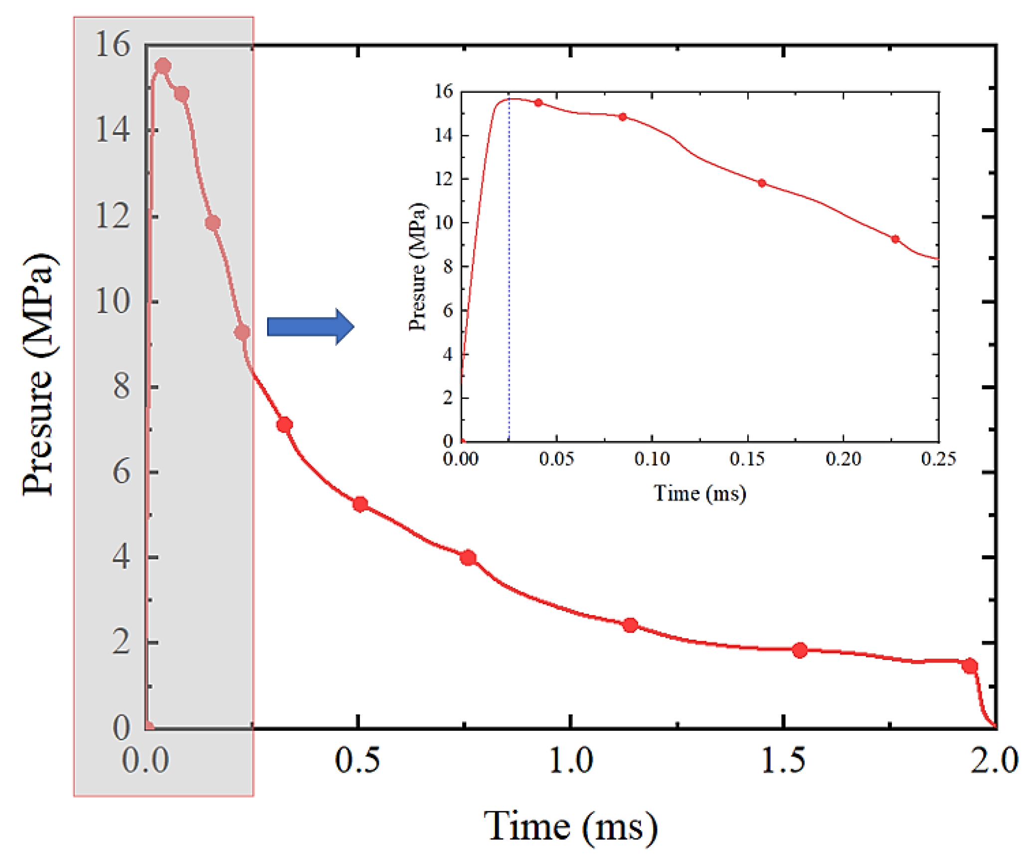
3.6. Explosion Source and Shock Wave

The explosion source is a 27.22 kg HBX-1 explosive charge. The center of the explosive charge is located on the same axis as the geometric center of the cylindrical shell, situated 7.62 m away from the outer surface of the front face (Figure 4). Notably, the cylindrical shell was not placed deep into the water, and consequently, a low hydrostatic pressure acted on the outer surface of the cylindrical shell, such that the hydrostatic pressure is neglected. The relationship between the pressure and time of the incident pressure wave acting on the cylindrical shell is presented in Figure 5. The curve shape intuitively indicated that the shock wave in water exhibited the characteristics of the rising and falling stages. The shock wave manifests an extremely steep front and rapidly attains its maximum amplitude. In contrast, the falling stage approximately decays according to the exponential function relation. The curve indicated that the waveform is initially steep, and the amplitude rapidly decreased with time. The duration of the complete process exceeds a few milliseconds, thereby reflecting the instantaneity of explosion impact and the strong dynamic and nonlinear characteristics of the load.

4. Model Validation

Kwon YW and Fox PK [17] conducted a physical model test and numerical simulation of UNDEX. Their physical model constituted a closed cylindrical shell immersed in a pool loaded with an explosive charge. Their numerical simulation adopted both finite element and boundary element methods. More specifically, they conducted a structural analysis using the VEC-DYNA3D code. Considering their research as an example, the rationality of the calculation results of the model was verified. Subsequently, the corresponding strain–time curve was extracted, considering the two measuring points B1 and C1 on the cylindrical shell as the reference, as depicted in Figure 4.
The results of three groups of data within 8 ms are comparatively presented in Figure 6. Despite using diverse simulation software and methods, the three groups of curves were observed to attain an initial peak, which later declined drastically, and eventually, displayed fluctuations. Although the amplitude, frequency, and phase of vibration exhibited a certain deviation, the variations were marginal. Overall, it was consistent in terms of shape, strain response law, and variation trends, which verified the reliability of the simulation method.

5. Flow Field Characteristics

The pressure diagram of the three-dimensional flow field at the instant of the shock wave of far-field UNDEX acting on the closed cylindrical shell is illustrated in Figure 7.
At t = 0.01 ms, the initial condition at which the shock wave impacts the cylindrical shell forms a positive pressure zone on the front face (Figure 7a). After the explosive charge is detonated underwater, the detonation products emerging from the explosive charge expand rapidly outward. The sudden release of a considerable amount of energy instantly compresses the surrounding fluid, forming a high-speed shock wave propagating in the water. If the cylindrical shell is perpendicular to the movement direction of the wavefront, the incident wave is generated at the fluid–structure surface. Consequently, the hydrodynamic pressure increases rapidly and forms a positive pressure zone.
At t = 0.03 ms, a negative pressure zone is formed near the center of the front face (Figure 7b). Owing to the fluid–structure boundary, the velocity of the fluid suddenly becomes zero. The instant the shock wave front impacts the front face in a direction perpendicular to the moving direction of the wavefront. The fluid pressure is suddenly increased, and a reflected rarefaction wave propagating in the direction of the explosive charge is formed at a fluid–structure interface. The rarefaction wave and incident wave are superimposed adjacent to the front face such that the pressure in this area is reduced drastically and is less than the surrounding pressure. As the cavitation pressure of water is achieved, a negative pressure region is formed.
At t = 0.06 ms, the fluid flow around the circular cylinder occurs simultaneously (Figure 7c). At the wavefront impacts the obstruction, it encounters a cylindrical shell of finite size in the propagation of the shock wave in water. The fluid flow around the circular cylinder initiates from the front to the rear face, whereas the shock wave acts vertically on the front face. However, the pressure on the front face abruptly increased to the level of reflected overpressure. Moreover, the fluid surrounding the cylindrical shell did not encounter obstacles, except for the front face. As the overpressure in the shock wave did not increase, the overpressure varied across multiple positions of the cylindrical shell. Under the action of the rarefaction wave, the fluid present near the front face flowed upward and downward from the central axis of the front face at the same time. Under the influence of the incident shock wave, the fluid at the top and bottom of the cylindrical shell moving direction varied, thereby forming a “cyclone” moving counterclockwise and clockwise, respectively, which emerges into a continuously spread circulation.
At t = 0.22 ms, the circulation develops further, and the rear face encounters complex stress (Figure 7d). The fluid flows symmetrically surrounding the top and bottom of the cylindrical shell, from the front to the rear face, thereby forming a diffracted wave. The superposition of the diffracted wave and transmitted wave acts on the center of the rear face, resulting in the continuous rise of fluid pressure. The fluid pressure on the rear face was at a high level with a state of more complex stress than that on the front face or the top and bottom surface of the center of the cylindrical shell. Moreover, the fluid bypassed the top of the cylindrical shell by flowing counterclockwise to the rear face, whereas the fluid bypassed the bottom of the cylindrical shell by flowing clockwise to the rear face. The pressure gradually increased with the convergence at the center of the rear face. In contrast, the pressure on the front face gradually decreased because of the action of the rarefaction wave. As the two circulations continued to flow around the rear face, they collided with each other and the pressure in the collision area gradually increased. After a cylindrical shell with a small length and diameter is influenced by the shock wave, the fluid flows were simultaneously generated at the top, bottom, left, and right of the cylindrical shell. At this instant, four diffracted wave regions were formed at the convergence of the fluid waves at a certain distance from the rear face, and the pressure in those areas was extremely high.
At t = 0.35 ms, the circulation bypassed the rear face thereafter, as depicted in Figure 7e. The circulation continues to flow in the direction of shock wave propagation. The rear face continuously compressed the fluid in contact with it, which generates radiation pressure waves and transmission waves. Owing to the deformation of the cylindrical shell under the action of the shock wave, the gap between the structure and fluid continued to widen, which signified the continuous reduction in pressure prevailing in this area and the continuous expansion of the negative pressure area.
The entire process of the UNDEX shock wave from the incident and diffusion on the front face as well as the diffraction and circulation to the rear face is portrayed in Figure 7. After the fluid acts on the cylindrical shell by the shock wave in water, the pressure range of the flow field was classified into positive and negative pressure zones. In chronological order: an initial positive pressure region, followed by a negative pressure zone. In space: in the direction of shock wave propagation, the positive pressure zone was at the front, and the negative pressure zone was situated at the rear. Thereafter, a negative pressure zone formed behind the positive pressure zone, and the action area of the positive pressure zone was smaller than that of the negative pressure zone. Initially, the positive pressure zone appeared at the center of the front face, after which it was observed along the top and bottom sides of the front face. Eventually, it converged at the center of the rear face before flowing away. The pressure variations in the flow field started at the center of the front face and transferred to two sides of the rear face. Ultimately, it was transferred from the two sides of the rear face toward the center of the rear face.
As the shock wave of UNDEX impacted the cylindrical shell, the structure traveled along the propagation direction of the shock wave. In addition, stress waves were formed in the fluid and cylindrical shell. More importantly, incident waves reflected rarefaction waves, radiation pressure waves, transmitted waves, and diffracted waves were generated in the vicinity of the fluid–structure interface, which resulted in local cavitation and fluid flow around the circular cylinder. The shock wave caused by UNDEX acted on the cylindrical shell, and the interaction between the fluid and cylindrical shell formed the flow field pressure. Subsequently, the flow field pressure reacted on the cylindrical shell to produce a dynamic response. The vibration and deformation of the cylindrical shell reacted to the fluid, affected the pressure distribution of the flow field, and further affected the structural stability of the cylindrical shell. This process revealed the transient process of shock wave propagation, reproduced the behavior of fluid stratification, and the vortex generation caused by the fluid bypassing the cylinder, which obtained the distribution characteristics of the flow field pressure.

6. Dynamic Response of Cylindrical Shell

6.1. Plastic Deformation

Generally, the cylindrical shell is utilized as a bearing component outside the structure. However, its deformation and vibration can deteriorate its structural strength and stability, apart from influencing the operation of the internal equipment. As the UNDEX shock wave acted on the cylindrical shell, the shell will produce local distortion and deformation that causes folding and fracture in severe cases. To understand the plastic deformation of cylindrical shells impacted by the UNDEX, the equivalent plastic strain was considered to characterize the structural plastic deformation. Thereafter, we analyzed the local response of the cylindrical shell under explosion. The typical equivalent plastic strain isosurface diagram of the cylindrical shell in the evolution of several analysis steps for the deformation process is depicted in Figure 8.
As observed in Figure 8, the equivalent plastic strain is concentrated on two sides of the front face (Figure 8a), the center of the rear face (Figure 8b), the exterior ring of the endcap (Figure 8c), and the center of the endcap (Figure 8d). Based on the shock wave acting on the cylindrical shell, the transmission path of the plastic strain generated by the shell in the time history can be described as follows: “two sides of front face” → “center of rear face” → “exterior ring of endcap” → “center of endcap.” As the exterior ring of the endcap was located at a higher strain compared to other positions (Figure 8c,d), the protection of the position with high plastic strain should be strengthened to improve the structural resistance and achieve the purpose of preservation.
Yin, Caiyu, et al. [44] performed the numerical simulation of a shell structure under the action of the UNDEX shock wave. The research object was a “capsule” composite structure with a cylindrical body in the middle and at two hemispherical ends. Compared with Yin, Caiyu, et al. [44], the “capsule” structure did not exhibit apparent stress concentration in the exterior ring of the endcap. Consequently, the “capsule” structural shape alleviated the edges and corners between the cylindrical body and the end from the structural contour, which effectively reduced the stress concentration at the exterior ring of the endcap of the cylindrical shell structural shape. Moreover, it evenly transferred the stress to the two hemispherical ends of the combined structure. The stress distribution of the exterior ring of the endcap and two sides of the cylindrical shell can be improved through shape optimization. Therefore, this paper focuses on the front and rear faces.
Based on the perspective of energy conservation, the shock wave generated by the explosion transmits the explosion energy to the cylindrical shell through the water medium of the flow field. Owing to the lack of time required to completely absorb the entire energy, the internal force of the cylindrical shell is redistributed under the restriction of the fluid. In the process of internal force redistribution, the plastic strain accumulated in the region, which caused regional plastic deformation of the shell and the formation of wrinkles to achieve energy absorption. Therefore, this is a combined process of energy absorption, conversion, and energy dissipation, which suggest high plastic strain in specific areas. The shell in these areas displays an energy absorption effect that absorbs the impact energy generated by the UNDEX for energy dissipation through deformation. Simultaneously, the accumulation of strain causes significant potential safety hazards to the performance of the structure. Material failure occurs directly when the accumulated energy of plastic strain attains the ultimate load of the material.

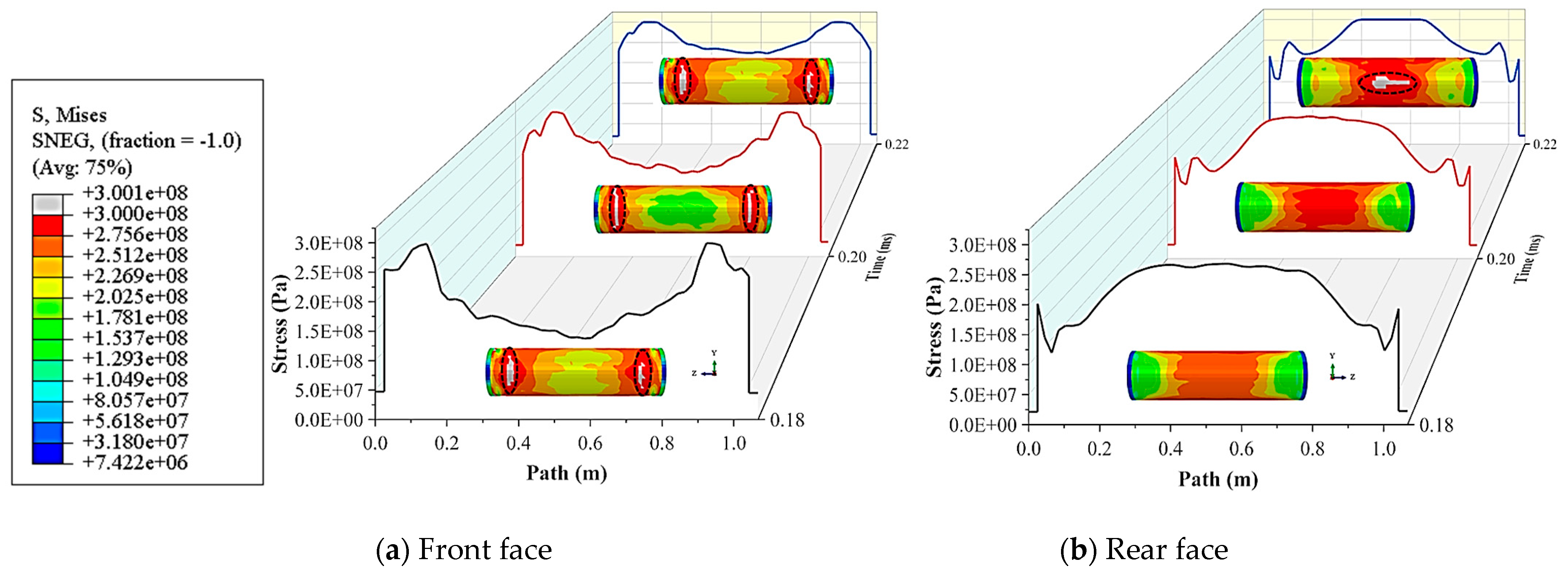
6.2. Yield Characteristics

To determine the capacity of the material to withstand the impact caused by the explosion and observe the area of material damage, the dynamic yield characteristics of the cylindrical shell are described herein. Accordingly, the stress states of the front and rear faces were selected for analysis. The stress diagram of the front and rear faces is presented in Figure 9. To distinguish the yield area from the non-yield area, the yield strength of the material was selected as the criterion, and the stress limit was set at 300 MPa. The component exceeding 300 MPa is demarcated as gray to indicate that the material has attained yield stress and is in the yield state.
Although the same materials were used for the front and rear faces, the yield time of the two faces followed a particular sequence, as depicted in Figure 9. In particular, the front face yielded 0.18 ms and the rear face yielded 0.22 ms. The yield position appears on two sides of the front face, whereas the rear face appears at the center. Both the front and rear faces present a banded yield zone. The yield zone of the front face presents a “vertical strip,” whereas the rear face presents a “horizontal strip.”
If the shock wave energy increases according to the relationship between the stress direction and position, the crack can be generated in damage mechanics. As inferred, the front face is primarily subjected to the impact load in the X-direction, forming the shear force created by the front and rear tearing perpendicular to the ZY plane. The tearing-mode crack is initiated when the shear force exceeds the material yield stress. The pressure on the rear face varies from that on the front face. The center of the cylindrical shell is pulled in the Z-direction, which can easily form an opening-mode crack.

6.3. Failure Mode

In the air, the pressure variations caused by an explosive charge have a marginal effect on the deformation of the far-field structures. Simultaneously, the deformation of the structure poses a slight effect on the adjacent air, and the behavior of the structure approximately satisfies the behavior characteristics under the free field. Although water is a homogeneous fluid, the variations between water and air in terms of their density, compressibility, expansibility, sound velocity, and other physical properties result in variations in the physical phenomena of explosive charges exploding in air and water.
As observed in Figure 7 and Figure 9, the deformation of the cylindrical shell is adequate at 0.22 ms. Based on the displacement field of the cylindrical shell at 0.22 ms displayed in Figure 10, we analyzed the variation law of the displacement field along the cylindrical body between the front and rear faces. The front face’s displacement form diagram is shown in Figure 10a, and the central axis line (Figure 4 “Line 1”) of the front face’s displacement data diagram is shown in Figure 10b.The rear face’s displacement form diagram is shown in Figure 10d, and the central axis line (Figure 4 “Line 2”) of the rear face’s displacement data diagram is shown in Figure 10c.
At 0.22 ms, the positions of the peak displacement of the front and rear faces varied. The displacement curve shapes of the front face were significant in the middle and small on two sides, which is analogous to a “hat”. The left- and right-hand sides are initially raised and then become concave with a maximum and minimum value, respectively, whereas the middle section remains relatively flat. The rear face denotes the opposite, and the curve shape is small in the middle and large on the two sides, similar to a “tray” with a slight uplift in the bottom center. The minimum existed on the left- and right-hand sides of the rear face, and the maximum occurred in the middle.
The displacement nephogram of the cylindrical shell at 0.22 ms is illustrated in Figure 11. To analyze the failure mode of the cylindrical shell, the deformation amplification factor was 70. The failure mode can be segmented into an overall failure and a local failure. The overall failure is primarily related to the peak load, structure type, constraint conditions, and other factors. Moreover, the overall failure is characterized by global buckling deformation and internal force, whereas the local failure characteristics are observed only in certain regions. Fundamentally, the local failure is related to the properties of materials but not to the constraint conditions and structural types. The characteristic of the local failure is that the damage is confined to the local area, where concavity, folds, and even ruptures occur.
Under the action of the UNDEX shock wave, the cylindrical shell as an entity deformed towards the rear face, as observed in Figure 11, and the concave shape in the front face deformed noticeably to form an “arch.” Although the cylindrical shell moved toward the rear face, the force of the surrounding water lagged and failed to produce a sizeable instantaneous displacement. Thereafter, a negative pressure zone was generated at both ends of the cylindrical shell (Figure 7d), which induced the characteristics of a “sucking disc” shape in the endcap. According to the apparent external attributes of stress and the failure behavior of the closed cylindrical shell at both ends under the action of far-field UNDEX, its shape was analogous to a dumbbell. At both ends of the cylindrical shell, the damage form caused by the negative pressure constraint provided by the water is called dumbbell-shaped damage effect (Figure 11). The negative pressure of the water at both ends of the cylindrical shell forms a strong constraint on the components. The displacement of the middle of the cylindrical shell along the X-direction is significantly greater than that at both ends. The entire structure is tensioned along the Z-direction, and the shear force at the front face is much greater than that at the rear face.
Under the complex fluid–structure interaction, the front face is concave on two sides and slightly arched in the middle. The front face forms an “ellipsoid” shape displacement field (Figure 10a), and the diameter shrinkage occurs at the end of the cylindrical shell (abef area in Figure 11). The restraint of the front face is stronger, and its shear failure and diameter shrinkage are more prominent, which is consistent with the stress yield zone displayed in Figure 9a. The rear face was primarily caused by the “arch” resulting from the concave impact on the front face, which compressed the fluid in its contact and generated an “H-type” displacement field (Figure 10d). The fluid formed a reaction force that was characterized by a larger force in the middle and a smaller force on two sides of the rear face.
According to the above-mentioned plastic deformation analysis of the cylindrical shell, the closed cylindrical shell displayed a trend of “arch” deformation along the direction of shock wave propagation under the action of far-field UNDEX. Furthermore, based on the response characteristics of the flow field, the deformation of structures adjacent to the fluid at both ends resulted in the formation of negative pressure, which consequently imposed strengthened constraints on the cylindrical shell.

7. Conclusions

In this paper, ABAQUS finite element software was used for numerical modeling and numerical calculation. The flow field response characteristics, plastic deformation, yield characteristics, and failure modes of the closed cylindrical shell under the far-field side-on UNDEX shock wave were analyzed and summarized. The major conclusions of this research are stated as follows:
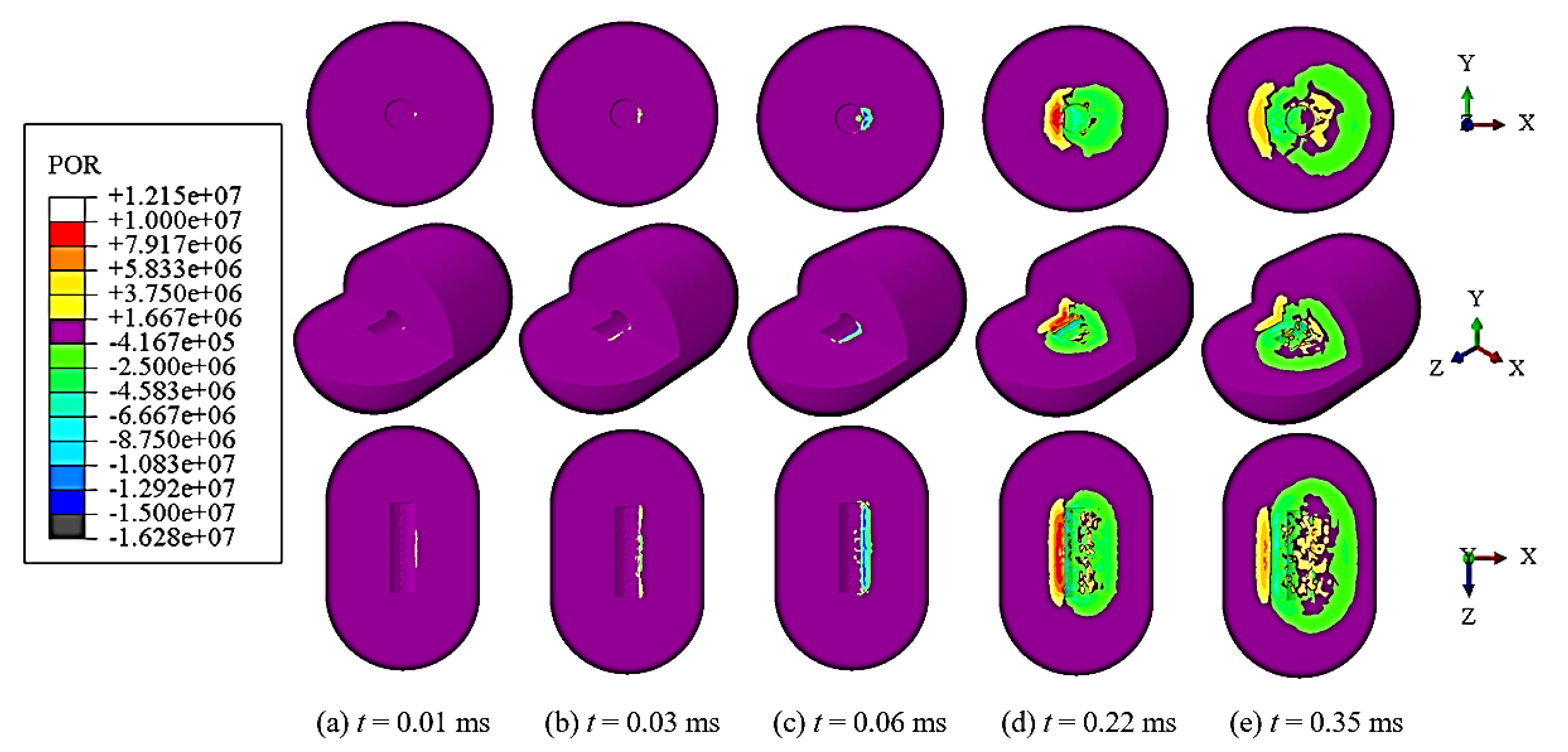
  • In case the shock wave acts on a finite cylindrical shell in water, the flow occurs in the surroundings of the circular cylinder, which consequently generates incident waves, rarefaction waves, radiation pressure waves, diffracted waves, transmission waves.
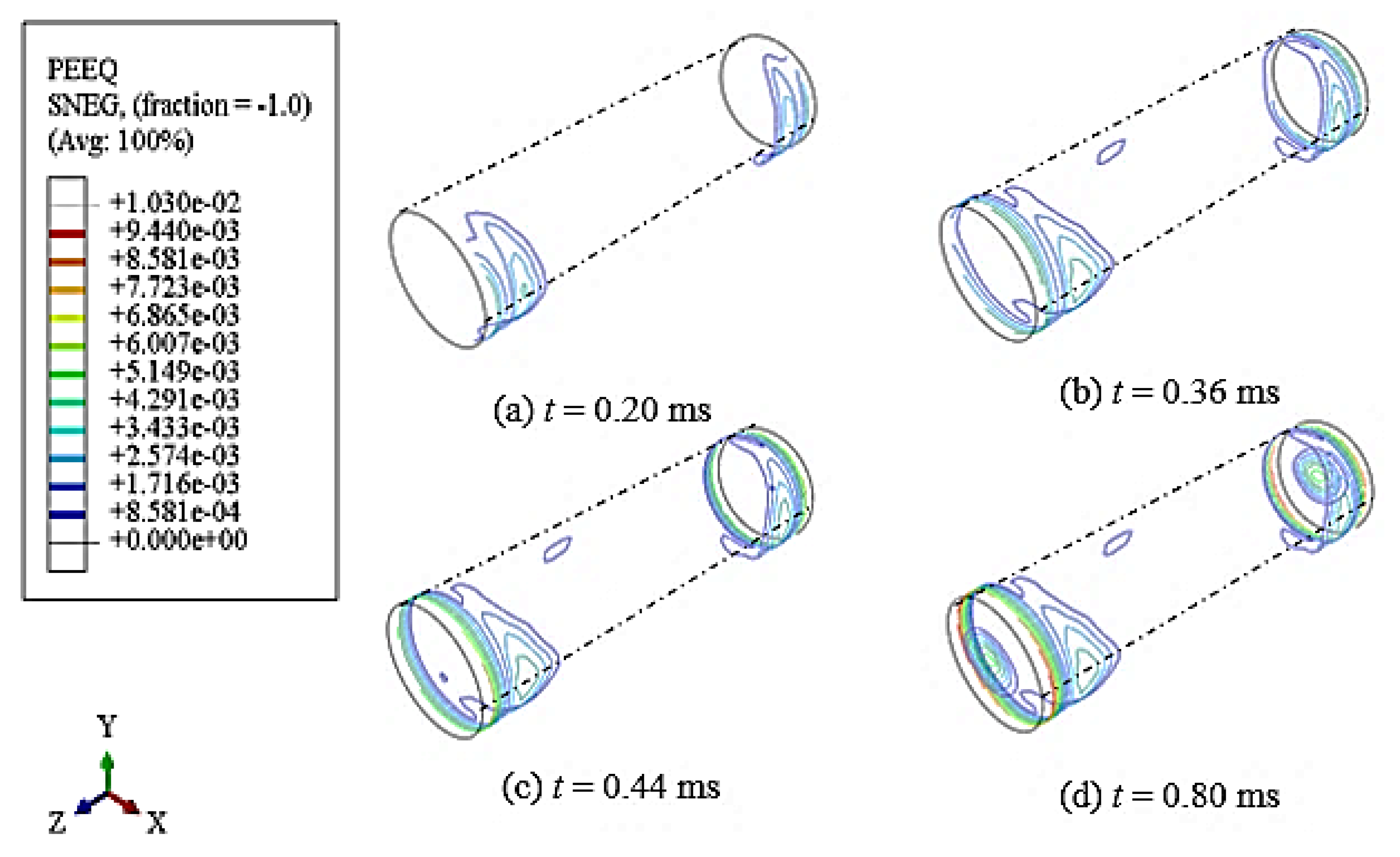
  • The plastic deformation of the cylindrical shell experiences the process of “two sides of the front face” → “center of rear face” → “exterior ring of endcap” → “center of endcap.” Compared with other positions, the exterior ring of the endcap undergoes a higher strain, and a uniform stress distribution is achieved through shape optimization.
  • There is a sequence in the yield time of the materials on the front and rear faces. The front face yields before the rear face. The yield position appears on two sides of the front face, and the yield zone presents a vertical strip. In particular, the yield position appears at the center of the rear face, and the yield zone displays a transverse strip. The front face is primarily subjected to shear force, and the rear face is mainly subjected to tensile force.
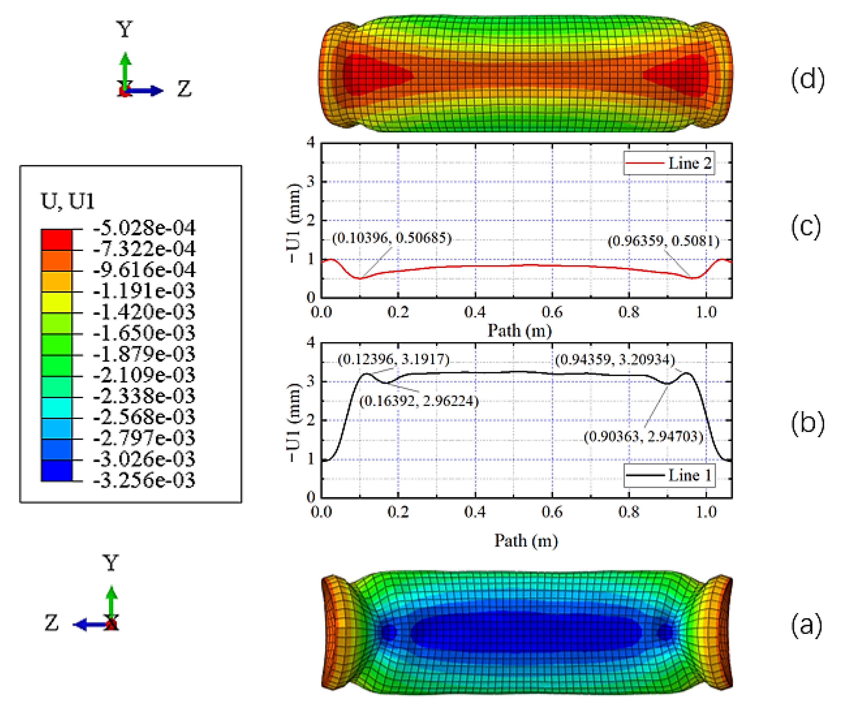
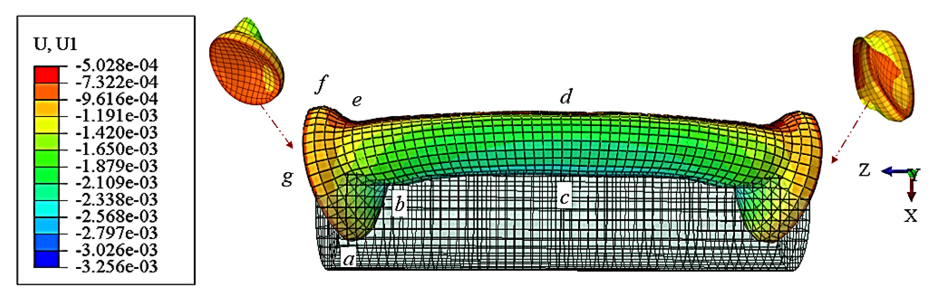
  • Under the instantaneous impact of the UNDEX shock wave, the fluid at both ends of the cylindrical shell cannot be compressed in time. The negative pressure of the fluid at both ends of the cylindrical shell forms a strong constraint that renders the shell deformation uncoordinated. In addition, closed cylindrical shells tend to exhibit “arch” deformation along the propagation direction of the shock wave. At 0.22 ms, the positions of the peak displacement of the front face differ from those of the rear face. The displacement curve shape of the front face is analogous to a “hat,” whereas the curve of the rear face is similar to a “tray” with a slight uplift at the bottom center. The front face forms an “ellipsoid” shape displacement field, and the rear face generated an “H-type” displacement field. The negative pressure zone generated at both ends of the cylindrical shell induces a “sucking disc” shape in the endcap form. The end of the cylindrical shell produces a diameter shrinkage, and the overall shape of the cylindrical shell is similar to a “dumbbell” shape with a dumbbell-shaped damage effect.

8. Discussion

Through numerical simulation, this paper reports the reappearance of the dynamic buckling of the cylindrical shell. The fluid flow surrounding the circular cylinder, diffraction, and cavitation generated in shock wave propagation provide restraints. The restraints at both ends of the cylindrical shell cause a significant deviation in the stress state between the front and rear face, which substantially impacts the evaluation of the bearing capacity of the cylindrical shell.
This paper aims to reproduce several behaviors of the fluid–structure interaction under specific conditions. Owing to the research on specific physical phenomena, it is inevitable to weaken or neglect other factors. In the far-field side-on UNDEX, the cylindrical shell is subjected to hydrostatic pressure and various dynamic shock combinations. In the future, indoor and outdoor model tests should be used to conduct the UNDEX test with a closed cylindrical shell. Thus, appropriate planning should be conducted to deeply analyze the deformation, failure mode, and progressive damage evolution of each characterization unit of the cylindrical surface under the impact environment, using a simple physical and mechanical model to explore the complex mechanism behind the physical phenomenon, to enrich and develop the research of UNDEX.

Author Contributions

Y.W.: Investigation, Data collection, Software, Calculating, Writing—original draft, Writing—review and editing. H.D.: Methodology, Formal analysis, Writing—review and editing. T.D.: Data curation, Conceptualization, Writing—review and editing. X.X.: Review. All authors have read and agreed to the published version of the manuscript.

Funding

This work is financially supported by the National Natural Science Foundation of China (No. 51909268) and the China Postdoctoral Science Foundation (BX 2021115).

Institutional Review Board Statement

Not applicable.

Informed Consent Statement

Not applicable.

Data Availability Statement

Not applicable.

Conflicts of Interest

The authors declare that they have no known competing financial interests or personal relationships that could have appeared to influence the work reported in this paper.

References

  1. Li, J.; Hua, H. Transient Response of an Orthotropic Cylindrical Shell to an Underwater Explosive Loading. J. Reinf. Plast. Compos. 2008, 28, 1747–1762. [Google Scholar] [CrossRef]
  2. Rakotomalala, Q.; Khoun, L.; Leblond, C.; Sigrist, J.F. An advanced semi-analytical model for the study of naval shock problems. J. Sound Vib. 2021, 511, 116317. [Google Scholar] [CrossRef]
  3. Gupta, S.; Leblanc, J.M.; Shukla, A. Mechanics of the implosion of cylindrical shells in a confining tube. Int. J. Solids Struct. 2014, 51, 3996–4014. [Google Scholar] [CrossRef] [Green Version]
  4. Kiciński, R.; Szturomski, B. Pressure Wave Caused by Trinitrotoluene (TNT) Underwater Explosion—Short Review. Appl. Sci. 2020, 10, 3433. [Google Scholar] [CrossRef]
  5. De Camargo, F.V. Survey on Experimental and Numerical Approaches to Model Underwater Explosions. J. Mar. Sci. Eng. 2019, 7, 15. [Google Scholar] [CrossRef] [Green Version]
  6. Anas, S.M.; Alam, M.; Umair, M. Experimental and numerical investigations on performance of reinforced concrete slabs under explosive-induced air-blast loading: A state-of-the-art review. Structures 2021, 31, 428–461. [Google Scholar] [CrossRef]
  7. Qi, C.; Hu, Z.; Wang, S.; Jiang, Z.; Wu, H.; Yin, Z. Study on the Propagation Law of Water Hammer Wave in Underwater Blasting and the Reducing Effect of Air Curtain on Water Hammer Wave. Shock Vib. 2021, 2021, 9994071. [Google Scholar] [CrossRef]
  8. Saito, T.; Marumoto, M.; Yamashita, H.; Hosseini SH, R.; Nakagawa, A.; Hirano, T.; Takayama, K. Experimental and numerical studies of underwater shock wave attenuation. Shock Waves 2003, 13, 139–148. [Google Scholar] [CrossRef]
  9. Arora, H.; Hooper, P.A.; Dear, J.P. The Effects of Air and Underwater Blast on Composite Sandwich Panels and Tubular Laminate Structures. Exp. Mech. 2011, 52, 59–81. [Google Scholar] [CrossRef] [Green Version]
  10. Massoni, J.; Saurel, R.; Lefrancois, A.; Baudin, G. Modeling spherical explosions with aluminized energetic materials. Shock Waves 2006, 16, 75–92. [Google Scholar] [CrossRef]
  11. Lance, R.M.; Capehart, B.; Kadro, O.; Bass, C.R. Human Injury Criteria for Underwater Blasts. PLoS ONE 2015, 10, e0143485. [Google Scholar] [CrossRef] [PubMed] [Green Version]
  12. Wei, T.; Hargather, M.J. A new blast wave scaling. Shock Waves 2021, 31, 231–238. [Google Scholar] [CrossRef]
  13. Gupta, S.; Matos, H.; Shukla, A. Pressure signature and evaluation of hammer pulses during underwater implosion in confining environments. J. Acoust. Soc. Am. 2016, 140, 1012. [Google Scholar] [CrossRef] [PubMed]
  14. Gupta, S.; Matos, H.; LeBlanc, J.M.; Shukla, A. Shock initiated instabilities in underwater cylindrical structures. J. Mech. Phys. Solid 2016, 95, 188–212. [Google Scholar] [CrossRef]
  15. Sun, W.; Zhu, T.; Chen, P.; Lin, G. Dynamic implosion of submerged cylindrical shell under the combined hydrostatic and shock loading. Thin-Walled Struct. 2022, 170, 108574. [Google Scholar] [CrossRef]
  16. Shukla, A.; Gupta, S.; Matos, H.; LeBlanc, J.M. Dynamic Collapse of Underwater Metallic Structures—Recent Investigations: Contributions after the 2011 Murray Lecture. Exp. Mech. 2018, 58, 387–405. [Google Scholar] [CrossRef]
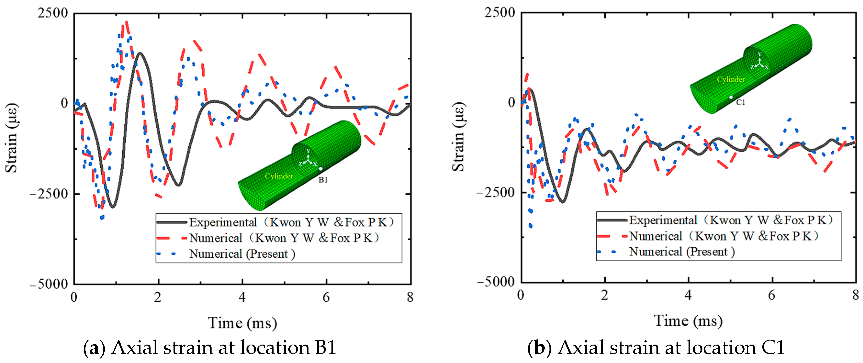
  17. Kwon, Y.W.; Fox, P.K. Underwater shock response of a cylinder subjected to a side-on explosion. Comput. Struct. 1993, 48, 637–646. [Google Scholar] [CrossRef]
  18. Wu, J.; Long, Y.; Zhou, Y.; Yu, Y.; Liu, J. Experimental study on the deformation and damage of cylindrical shell-water-cylindrical shell structures subjected to underwater explosion. Thin-Walled Struct. 2018, 127, 654–665. [Google Scholar] [CrossRef]
  19. Li, L.-J.; Jiang, W.-K.; Ai, Y.-H. Experimental Study on Dynamic Response and Shock Damage of Cylindrical Shell Structures Subjected to Underwater Explosion. J. Offshore Mech. Arct. Eng. 2011, 133, 011102-1. [Google Scholar] [CrossRef]
  20. Li, L.J.; Jiang, W.K.; Ai, Y.H. Experimental Study on Deformation and Shock Damage of Cylindrical Shell Structures Subjected to Underwater Explosion. Proc. Inst. Mech. Eng. Part C J. Mech. Eng. Sci. 2010, 224, 2505–2514. [Google Scholar] [CrossRef]
  21. Hung, C.F.; Lin, B.J.; Hwang-Fuu, J.J.; Hsu, P.Y. Dynamic response of cylindrical shell structures subjected to underwater explosion. Ocean. Eng. 2009, 36, 564–577. [Google Scholar] [CrossRef]
  22. Gao, F.; Ji, C.; Long, Y.; Cheng, L.; Zhao, C.; Wu, J.; Sun, Y. Numerical investigation of the dynamic response of CWC structures subjected to underwater explosion loading. Ocean. Eng. 2020, 203, 107214. [Google Scholar] [CrossRef]
  23. Da Silva Monteiro, L.L.; Netto, T.A.; Da Camara Monteiro, P.C. On the Dynamic Collapse of Cylindrical Shells Under Impulsive Pressure Loadings. J. Offshore Mech. Arct. Eng. 2016, 138, 041101-1. [Google Scholar] [CrossRef]
  24. Praba, R.P.S.; Ramajeyathilagam, K. Numerical investigations on the large deformation behaviour of ring stiffened cylindrical shell subjected to underwater explosion. Appl. Ocean. Res. 2020, 101, 102262. [Google Scholar] [CrossRef]
  25. Brett, J.M.; Yiannakopoulos, G.; van der Schaaf, P.J. Time-resolved measurement of the deformation of submerged cylinders subjected to loading from a nearby explosion. Int. J. Impact Eng. 2000, 24, 875–890. [Google Scholar] [CrossRef]
  26. Brett, J.M.; Yiannakopolous, G. A study of explosive effects in close proximity to a submerged cylinder. Int. J. Impact Eng. 2008, 35, 206–225. [Google Scholar] [CrossRef]
  27. Gauch, E.; Leblanc, J.; Shukla, A. Near field underwater explosion response of polyurea coated composite cylinders. Compos. Struct. 2018, 202, 836–852. [Google Scholar] [CrossRef]
  28. Zhang, Z.-F.; Ming, F.-R.; Zhang, A.M. Damage Characteristics of Coated Cylindrical Shells Subjected to Underwater Contact Explosion. Shock Vib. 2014, 2014, 763607. [Google Scholar] [CrossRef] [Green Version]
  29. Zhang, W.; Jiang, W. An Improved Shock Factor to Evaluate the Shock Environment of Small-Sized Structures Subjected to Underwater Explosion. Shock Vib. 2015, 2015, 451583. [Google Scholar] [CrossRef]
  30. Xiao, W.; Zhang, A.M.; Wang, S.P. The whipping response of a fluid filled cylindrical shell subjected to an underwater explosion. Mar. Struct. 2017, 52, 82–93. [Google Scholar] [CrossRef]
  31. Panahi, B.; Ghavanloo, E.; Daneshmand, F. Transient response of a submerged cylindrical foam core sandwich panel subjected to shock loading. Mater. Des. 2011, 32, 2611–2620. [Google Scholar] [CrossRef]
  32. Huang, S.; Jin, Z.; Chen, Y. Underwater blast resistance of double cylindrical shells with circular tube stiffeners. Ocean Eng. 2021, 238, 109691. [Google Scholar] [CrossRef]
  33. Gish, L.A.; Wierzbicki, T. Estimation of the underwater implosion pulse from cylindrical metal shells. Int. J. Impact Eng. 2015, 77, 166–175. [Google Scholar] [CrossRef]
  34. Li, J.; Rong, J.-L. Experimental and numerical investigation of the dynamic response of structures subjected to underwater explosion. Eur. J. Mech. B Fluids 2012, 32, 59–69. [Google Scholar] [CrossRef]
  35. Červený, V. Fermat’s variational principle for anisotropic inhomogeneous media. Studia Geophys. Geod. 2002, 46, 567–588. [Google Scholar] [CrossRef]
  36. Meshbey, V.; Ragoza, E.; Kosloff, D.; Egozi, U.; Wexler, T. Three-dimensional Travel-time Calculation Based on Fermat’s Principle. Pure Appl. Geophys. 2002, 159, 1563–1582. [Google Scholar] [CrossRef]
  37. Gargano, A.; Das, R.; Mouritz, A.P. Finite element modelling of the explosive blast response of carbon fibre-polymer laminates. Compos. Part B Eng. 2019, 177, 107412. [Google Scholar] [CrossRef]
  38. Rigby, S.E.; Tyas, A.; Clarke, S.D.; Fay, S.D.; Reay, J.J.; Warren, J.A.; Gant, M.; Elgy, I. Observations from Preliminary Experiments on Spatial and Temporal Pressure Measurements from Near-Field Free Air Explosions. Int. J. Prot. Struct. 2015, 6, 175–190. [Google Scholar] [CrossRef]
  39. Nguyen, V.T.; Phan, T.H.; Duy, T.N.; Park, W.G. Numerical modeling for compressible two-phase flows and application to near-field underwater explosions. Comput. Fluids 2021, 215, 104805. [Google Scholar] [CrossRef]
  40. Klaseboer, E.; Khoo, B.C.; Hung, K.C. Dynamics of an oscillating bubble near a floating structure. J. Fluids Struct. 2005, 21, 395–412. [Google Scholar] [CrossRef]
  41. Rungsiyaphornrat, S.; Klaseboer, E.; Khoo, B.C.; Yeo, K.S. The merging of two gaseous bubbles with an application to underwater explosions. Comput. Fluids 2003, 32, 1049–1074. [Google Scholar] [CrossRef]
  42. Zhang, Q.-L.; Huang, X.-Y.; Li, Z. Coupled acoustic-structural analysis of a partially submerged circular RC column in an underwater explosion event: Factors to be considered for loading. Ocean Eng. 2021, 232, 109122. [Google Scholar] [CrossRef]
  43. Abaqus [Computer Software]. Abaqus Analysis User’s Manual; Dassault Systèmes Simulia Corp.: Johnston, RI, USA, 2019. [Google Scholar]
  44. Yin, C.; Jin, Z.; Chen, Y.; Hua, H. Shock mitigation effects of cellular cladding on submersible hull subjected to deep underwater explosion. Ocean Eng. 2016, 117, 221–237. [Google Scholar] [CrossRef]
  45. Jen, C.Y. Coupled acoustic-structural response of optimized ring-stiffened hull for scaled down submerged vehicle subject to underwater explosion. Theor. Appl. Fract. Mech. 2009, 52, 96–110. [Google Scholar] [CrossRef]
Figure 1. Schematic of physical model of UNDEX.
Jmse 10 01874 g001
Figure 2. Plastic strain diagram of cylindrical shell in UNDEX test (Adapted from reference [17]).
Jmse 10 01874 g002
Figure 3. Schematic of numerical model.
Jmse 10 01874 g003
Figure 4. Three-dimensional diagram of UNDEX test with layout of monitoring points (B1, C1) and monitoring lines (line 1, line 2).
Jmse 10 01874 g004
Figure 5. Shock pulse.
Jmse 10 01874 g005
Figure 6. Comparison diagram of experimental and simulation.
Jmse 10 01874 g006
Figure 7. Pressure diagram of three-dimensional flow field.
Jmse 10 01874 g007
Figure 8. Isosurface diagram of cylindrical shell equivalent to plastic strain evolution process.
Jmse 10 01874 g008
Figure 9. Stress diagram of front and rear faces.
Jmse 10 01874 g009
Figure 10. Displacement distribution diagram.
Jmse 10 01874 g010
Figure 11. Failure mode.
Jmse 10 01874 g011
Publisher’s Note: MDPI stays neutral with regard to jurisdictional claims in published maps and institutional affiliations.

