Article

Experimental Investigation on Vibro-Acoustic Characteristics of Stiffened Plate Structures with Different Welding Parameters

1
School of Naval Architecture, Ocean and Energy Power Engineering, Wuhan University of Technology, Wuhan 430063, China
2
Green & Smart River-Sea-Going Ship, Cruise Ship and Yacht Research Center, Wuhan University of Technology, Wuhan 430063, China
3
Wuchang Shipbuilding Industry Group Co., Ltd., Wuhan 430000, China
4
School of Science, Wuhan University of Technology, Wuhan 430070, China
*
Author to whom correspondence should be addressed.
J. Mar. Sci. Eng. 2022, 10(12), 1832; https://doi.org/10.3390/jmse10121832
Submission received: 25 October 2022 / Revised: 22 November 2022 / Accepted: 25 November 2022 / Published: 29 November 2022

Abstract

:
Varied welding process parameters result in different welding energy inputs and welding residual stresses, significantly impacting the vibro-acoustic characteristics. This work investigated the influence of different welding energy inputs on the vibro-acoustic characteristics of the stiffened plate structure. Several experiments on the stiffened plate structure with different welding energy inputs were conducted regarding modal, underwater vibration, and acoustic radiation. The results revealed that welding energy input had the most significant impact on the first-order natural frequency, and the impact first becomes higher and subsequently decreases as welding energy input increases. The welding energy input had relatively little effect on the peak point distribution of vibration and acoustic radiation curves but could affect the peak point amplitude. With the increase in welding energy input, the overall vibration acceleration level and sound radiation level in each frequency band decreased and then increased. The best result was obtained when the welding energy input was 167 J/cm with a welding current of 200 A, a welding voltage of 25 V, and a welding speed of 3.02–3.06 mm/s. Based on construction technology, this research can provide some instructive insights for enhancing the acoustic stealth performance of ships and marine structures.

1. Introduction

The vibration and sound radiation characteristics of the structure significantly impact the comfort of luxury ships, underwater vehicles’ acoustic stealth performance, and surface ships’ navigational concealment [1,2]. With the large scale and complexity of engineering structures, the stiffened plate structure has been one of the most typical joints owing to the outstanding strength-to-weight and stiffness-to-weight ratios. Therefore, research on the vibration and sound radiation characteristics of the stiffened plate structure is of great significance to the vibration and acoustic improvement of engineering structures.
Many investigations have been performed by employing analytical, empirical, experimental, and numerical methods to analyze the vibration and acoustic radiation characteristics of stiffened steel plate. Generally, the primary theoretical methods include the circumferential admittance approach (CAA) [3], the Rayleigh–Ritz method [4], the first Rayleigh integral, the first-order shear deformation theory [5], the space harmonic expansions method [6], travelling wave solution [7], and Fourier transform technique [8]. With the development of numerical simulation, the finite element method (FEM) and the boundary element method (BEM) were widely applied to explore the influence of geometric parameters on mechanical properties [9], and the vibration and acoustic effects of the stiffener. The result showed that the source and obstacle effects of stiffeners are significant [10]. Whilst this approach offers excellent accuracy at low frequencies, it suffers from a high computational cost due to the fine mesh required as the frequency increases [11]. A novel linear modal model was presented to overcome this deficiency in order to predict the vibration response and sound transmission through stiffened panels. The result demonstrated that the stiffeners can enhance vibro-acoustic coupling, leading to a significant reduction in the dominant resonance level [12]. Another semi-analytical approach based on the FEM and the space harmonic method had been proposed to reveal that types, periodic distances, and dimensions of periodic stiffeners have a different effect on the vibro-acoustic characteristics of periodically stiffened plates [13]. Moreover, to study more specific factors that affect the vibro-acoustic characteristics of the stiffened plate, Abderrazak et al. [14] explored the effect of stiffeners on the vibro-acoustic response using a semi-analytical formulation based on a modal expansion technique. The results revealed that stiffener shape, position, eccentricity, excitation position, and cross-modal coupling are the key points influencing the vibro-acoustic characteristics of the stiffened panel. Apart from these influencing factors, Kai et al. [15] proposed an analytical solution based on a double finite sine integral transform technique by considering boundary conditions and the number of stiffeners. Furthermore, some researchers studied the vibro-acoustic characteristics of the stiffened composite panels. Based on the theoretical and numerical method applied to the stiffened steel plate, a few efforts are performed to figure out the vibro-acoustic characteristics of submerged stiffened composite plates, stiffened sandwich plates, and stiffened laminated composite plates [16,17,18]. The research results could indicate that the type of composite material, and the number, distribution, and shape of stiffeners all affect the vibro-acoustic characteristics.
The above-mentioned studies show that stiffeners are efficient for enhancing stiffness and significantly impact the vibro-acoustic characteristics of the stiffened plate. Many approaches considering the effect of stiffeners have been proposed to control vibration and sound radiation. On the one hand, installing vibration isolators [19,20] and using absorbing materials [21,22,23] have become the primary method in engineering practice to enhance the acoustic and vibration characteristics of the structure. On the other hand, altering the plate’s structural form [8] and optimizing the stiffener layout and parameters [24,25] can fundamentally control the structure’s vibro-acoustic characteristics during the design phase.
Although the effecting factors and the improving approaches of the vibro-acoustic characteristics of the stiffened plate have been conducted in a large number of studies during the design and engineering practice phase, there is little literature concerning the effect of welding technology during the construction phase. For the manufacturing of stiffened plates, there are lots of welding methods, including tungsten inert gas (TIG) welding, metal inert gas (MIG) welding, submerged arc welding (SAW) [26], and friction stir welding (FSW) [27]. However, CO2 gas shielded welding is the most commonly used for processing. It inevitably produces welding deformation and residual stress due to the high concentration of heat and the rapid heating and cooling, which have adverse consequences on the stiffness [28]. Generally, stiffness is one of the most significant factors affecting the vibro-acoustic characteristics of the stiffened plate. Due to different welding parameters, the welding residual stress and deformation become more complicated, resulting in various stiffness distributions. As a result, the welding residual stress and deformation play vital roles in the vibro-acoustic characteristics of complex welded structures.
The study on the effect of welding residual stress and deformation on the structure’s vibration and sound radiation characteristics has gained much attention. Up to now, several related studies have been conducted to investigate the vibro-acoustic characteristics by considering the impact of geometric defects (deformation) and residual stress. Gu et al. [29] analyzed the effects of different geometric defect sizes and initial geometric defect density on the natural properties of doubly curved shallow shells. The results determined the significant influence of the initial defect on the natural frequency and mode. The vibration and sound radiation of cylindrical shell and flat plate structures under uniformly distributed residual stress and typical uneven residual stress distribution were also investigated [30,31,32]. The research demonstrated that the types and amplitude of residual stress affect the local stiffness matrix distribution of the structure, which in turn affects the structure’s dynamic response characteristics.
Based on the above analysis, such studies remain narrow in focus, dealing only with the influence of assumption-based and simple distributions of residual stresses on the natural frequency and vibration characteristics of plate and shell structures by analytical and numerical methods. In general, the residual stress and deformation will vary depending on welding parameters, which would have a more complicated impact on vibro-acoustic characteristics. To the best of the author’s knowledge, there is no research concerning the influence of welding parameters on the vibration and acoustic radiation behaviour of the stiffened plate through the experimental method, and the association between different welding energy inputs and vibro-acoustic characteristics needs to be revealed.
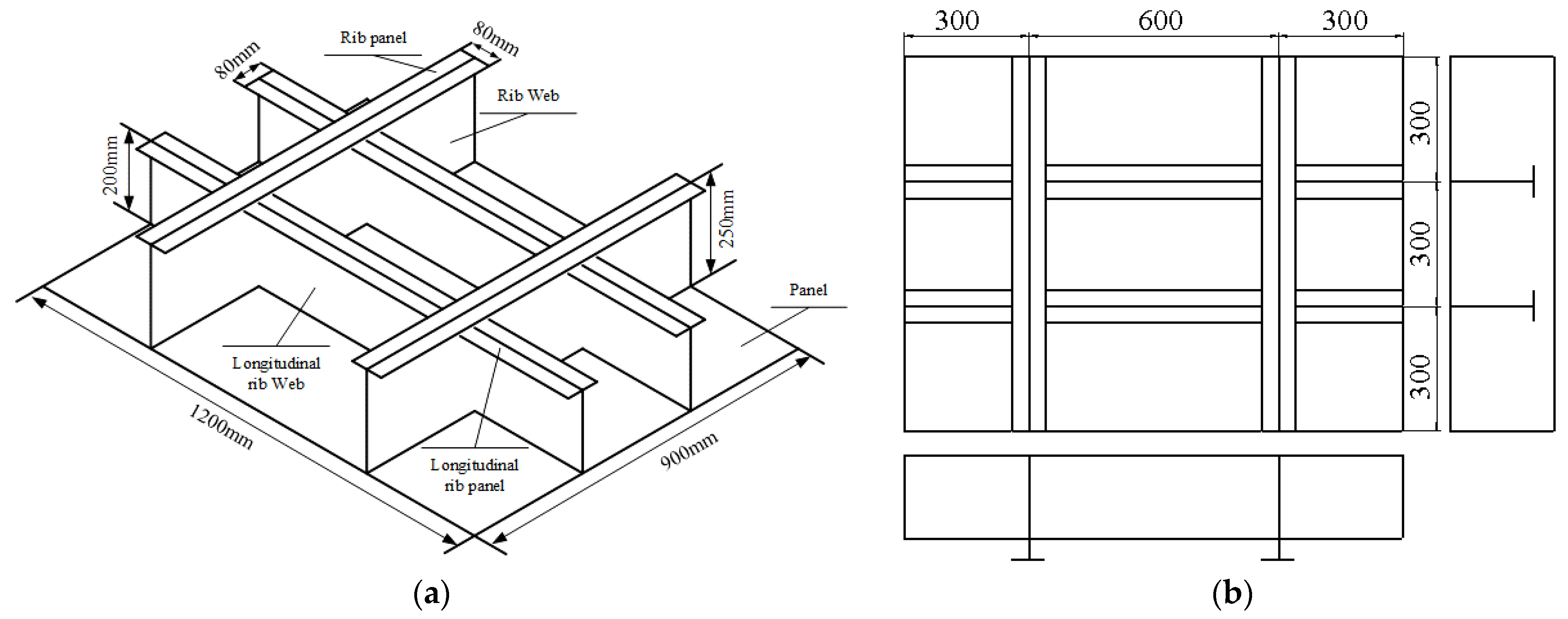
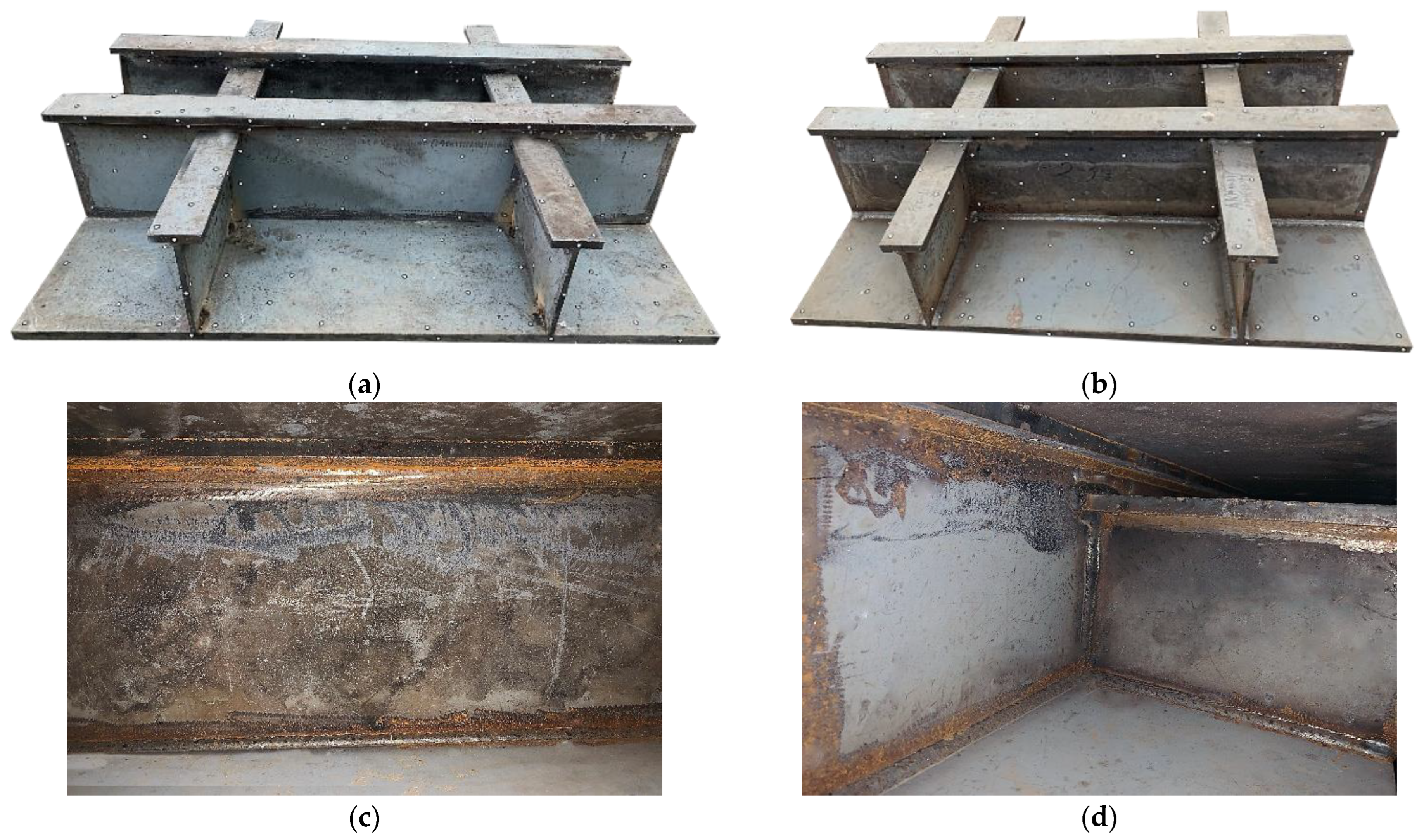
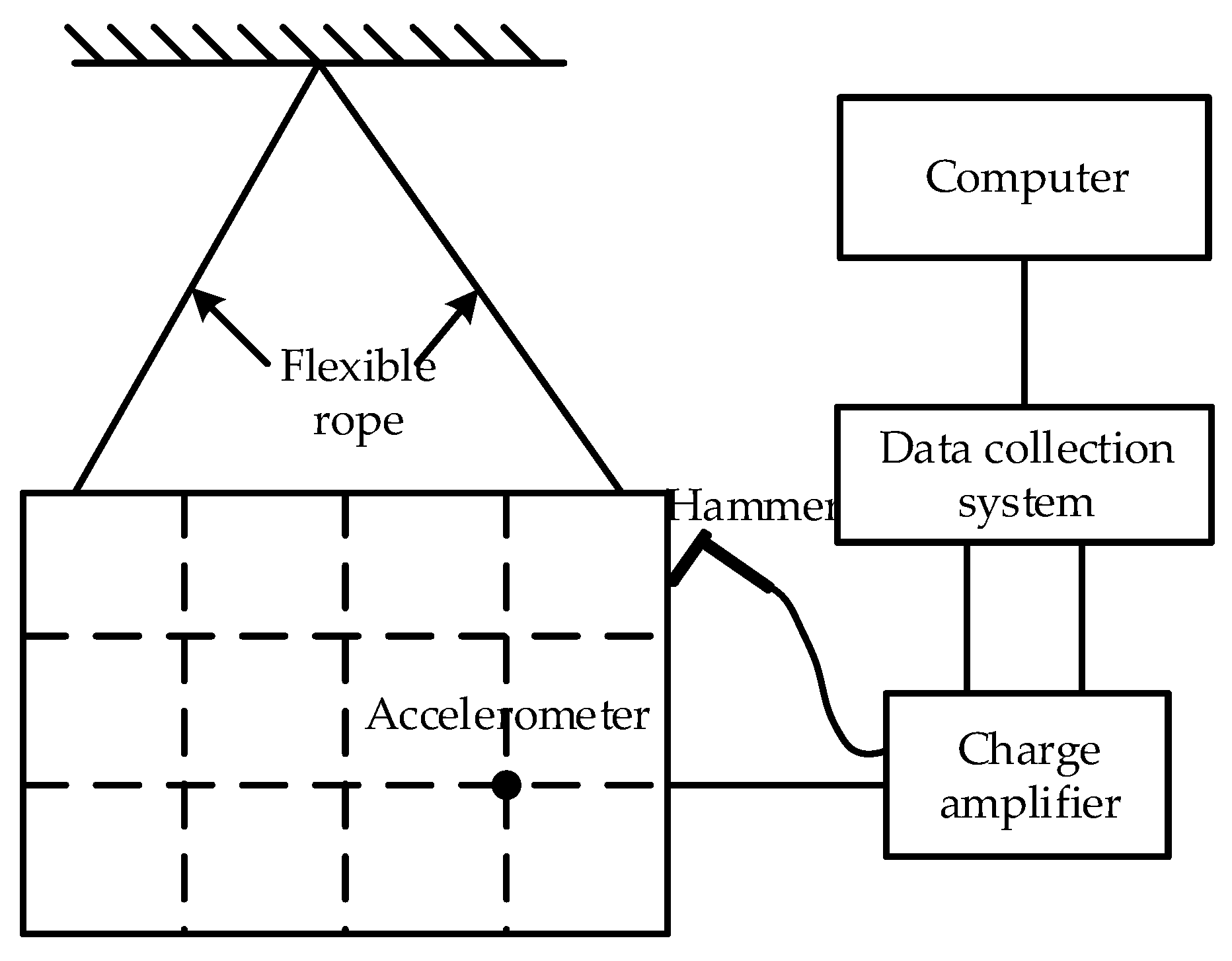
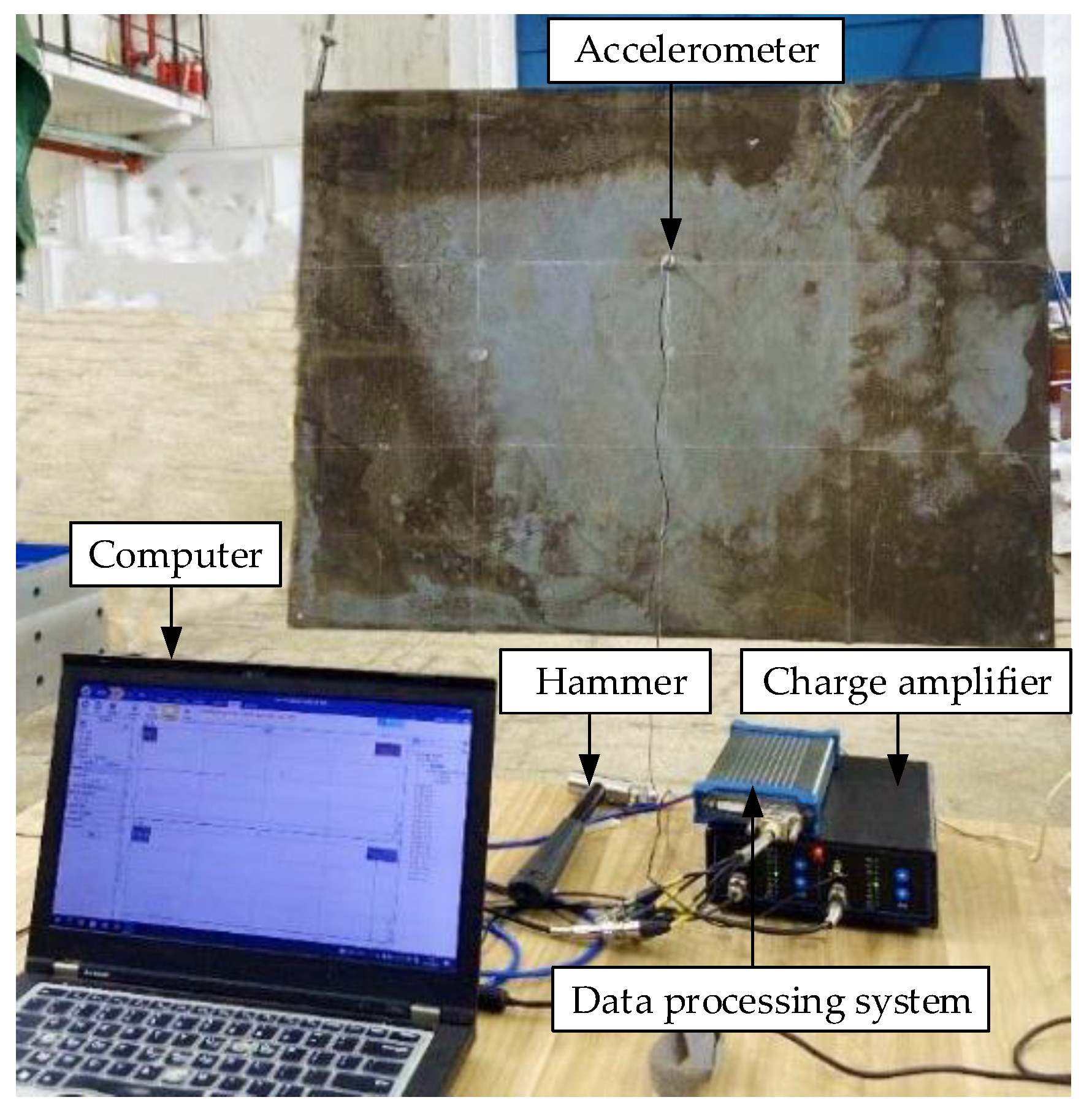
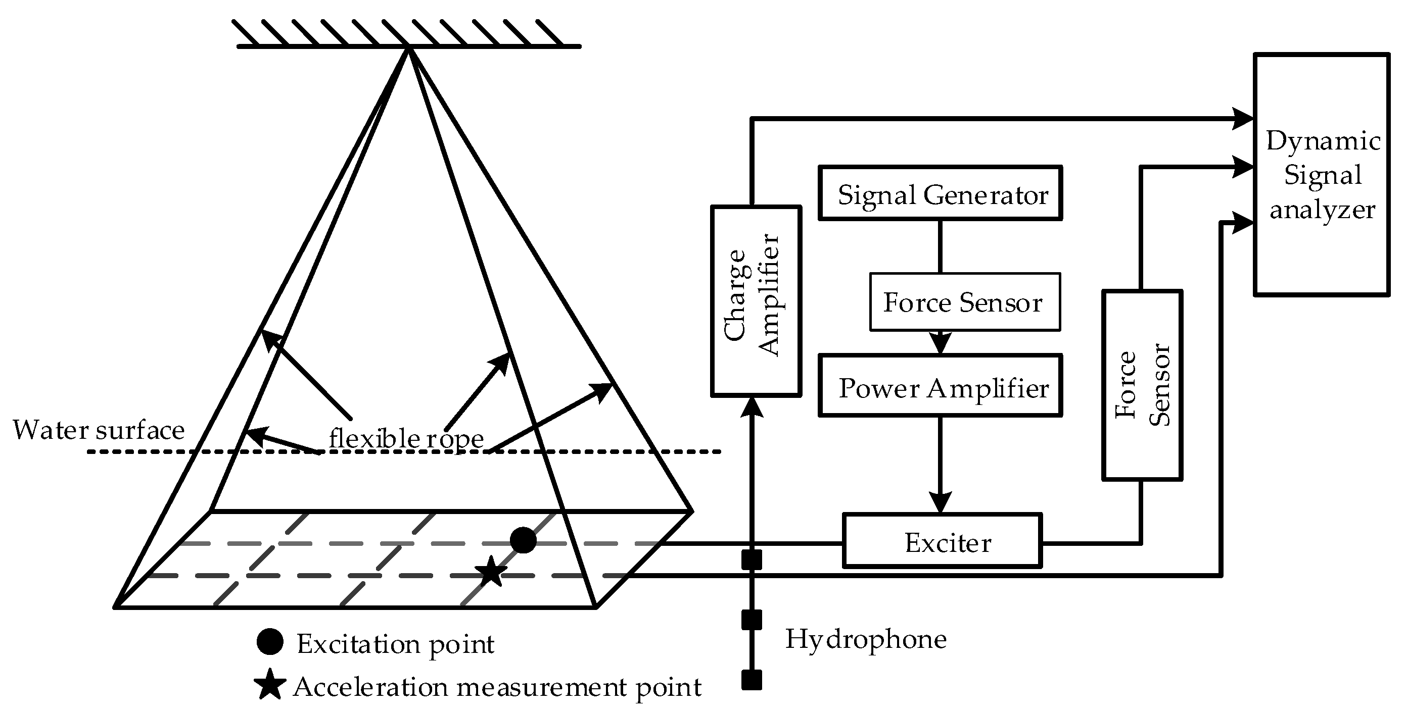
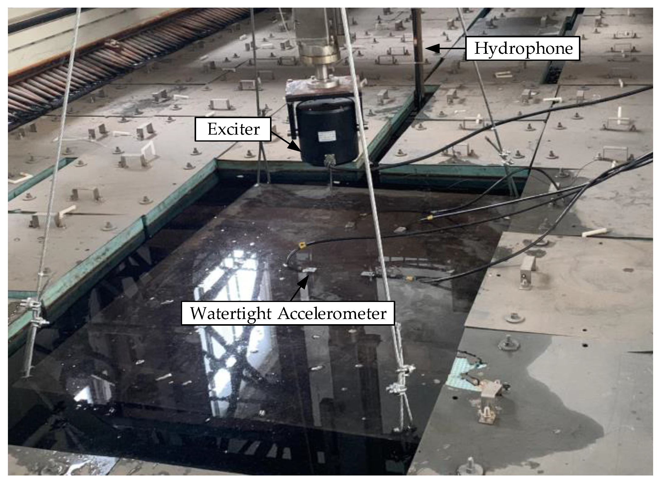
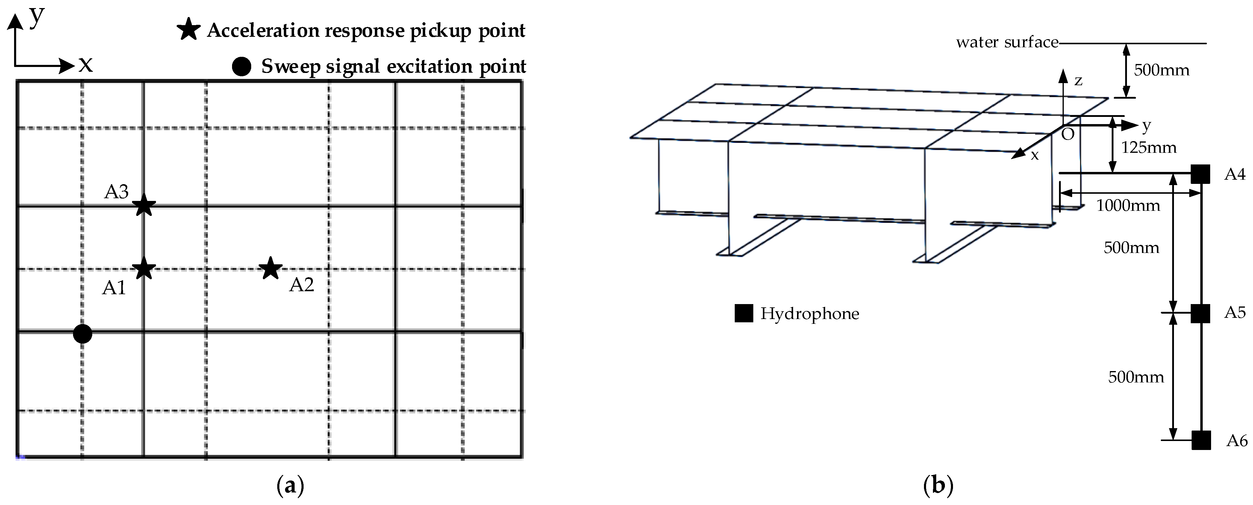
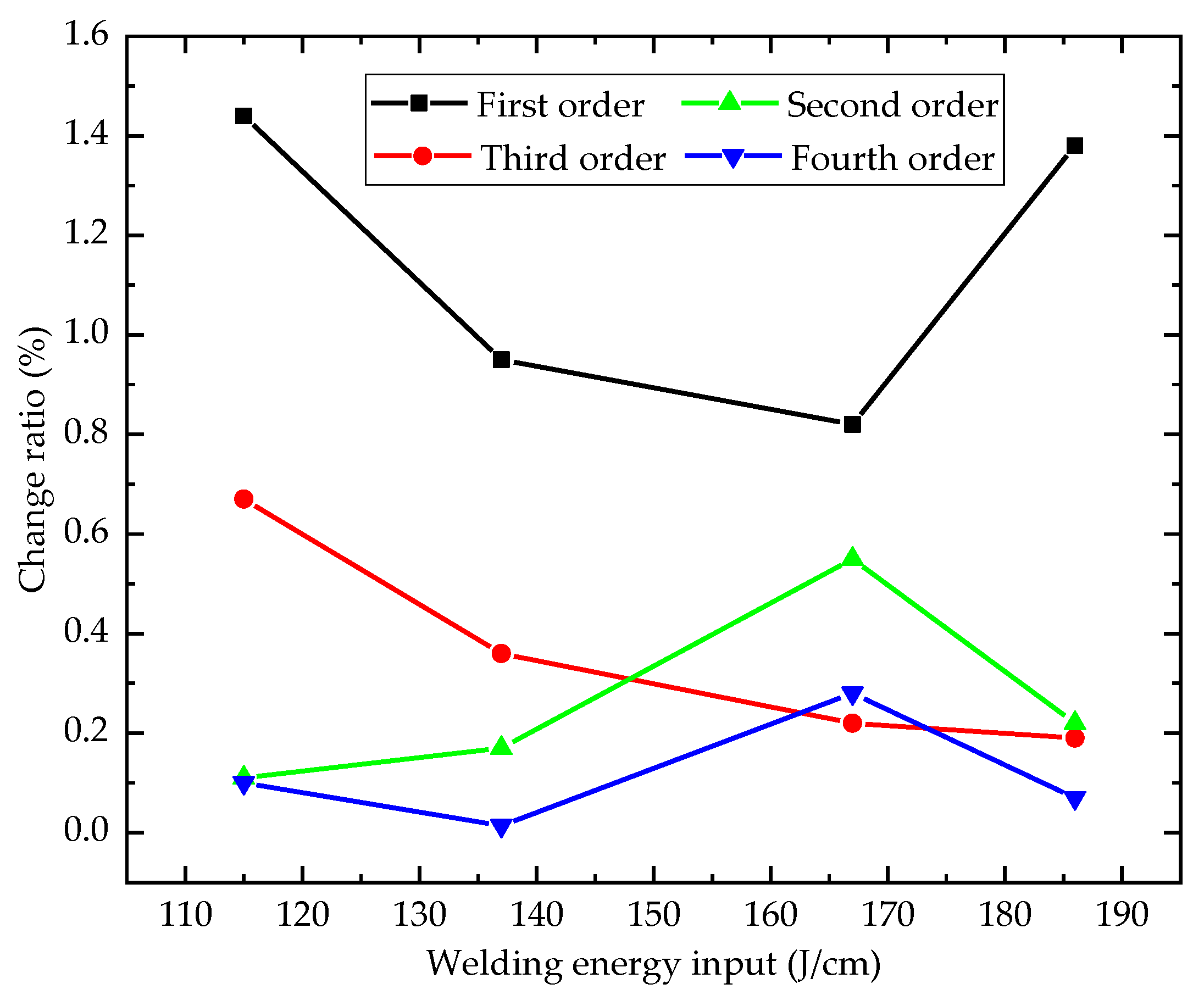
In this paper, the influence of different welding energy inputs on the vibro-acoustic characteristics of the stiffened plate was investigated. According to engineering practice experience, four sets of welding energy inputs were reasonably selected, and carbon dioxide shield welding was used in the same welding sequence. Experimental research based on modal, underwater vibration, and acoustic radiation tests was conducted to investigate the influence of different welding energy inputs on the vibro-acoustic characteristics. The test results analyzed the effect of welding energy inputs on the structure’s natural properties and dynamic response characteristics. The relationship between welding energy input and vibro-acoustic characteristics was also studied. This research could provide some instructive insights for improving the acoustic stealth performance of ships and maritime constructions.

2. Material and Method

2.1. Specimen Description

The stiffened structure is an economical and convenient way to significantly improve the stiffness and bearing capacity of the structure. By adjusting the size and spacing of the stiffeners on the plate, it is simple to meet the requirements of strength, stiffness, stability, and acoustic characteristics in engineering design, making it one of the most crucial research objects in the field of ships. In order to study the influence of different welding energy inputs on the hull structure’s vibro-acoustic characteristics, a stiffened plate structure was selected as the research object and experimental research work was carried out.
GJB 5347 standard was applied for the preparation of specimens, and this standard specifies 3–32 mm thick steel plates for the construction of naval structures. The GB/T 8110 standard was used for the welding procedure of specimens, and this standard is suitable for gas metal arc welding (GMAW), tungsten gas metal arc welding (GTAW), and plasma arc welding. The stiffened plate structure specimen is shown in Figure 1, and the dimensions are shown in Table 1. The material of the specimens in this test was L907A steel. The mechanical properties and chemical composition of the L907A steel are shown in Table 2. The detailed combination of the process parameters’ design of experiments is provided in Table 3.
The welding energy input is the energy delivered to the weld by the heat source per unit length. It is a critical factor that may affect the size and quality of the welds, particularly when depositing material onto previously deposited layers because of the remelting. This parameter depends on the travel speed (v), average arc current (I), and arc voltage (V). The following equation was used to calculate the welding energy input:
Q = I U v ( J / cm )
CO2 gas shielded welding was utilized for symmetrical welding during processing. Vertical fillet and horizontal welding shared the same parameters, namely a predicted welding energy input of 170 J/cm with a welding current of 160 A, welding voltage of 24 V, and welding speed of 2.26 mm/s. In order to study the influence of different welding energy inputs on the structure’s vibro-acoustic characteristics, several welding energy inputs were used during model processing. The process parameters, namely welding voltage (U), welding current (I), welding speed (v), and welding energy input (J/cm) are varied in the range of 23.5–28 V, 160–220 A, 3.1–3.55 mm/s, and 115–186 J/cm, respectively. Figure 2 depicts the stiffened plate specimen before and after welding. Figure 2a shows the overall state of the specimen before welding, and the components are only positioned by spot welding. Figure 2b is the general state of the specimen after welding.

2.2. Experimental Setup

The sound-free field environment is indispensable for conducting hydroacoustic experiments. Large background noise interference in natural waters makes it more challenging to reflect the laws of sound propagation in water. At the same time, anechoic pools provide a free field environment, where sound waves propagate to the boundary of the laid sound-absorbing material, and the energy is absorbed by the sound-absorbing material, thus, simulating the sound field conditions in infinite waters.
The test was conducted in the structural laboratory of Wuhan University of Technology, which is equipped with a 10 T, 5 T, and 1 T crane and an anechoic tank. The dimensions of the pool are X × Y × Z1/Z2, respectively, 8 m × 4 m × 3.1 m/2.2 m. The sound-absorption wedge is arranged on the six surfaces of the tank. If we remove the space occupied by the sound-absorption wedge, the effective use range of the anechoic tank is X × Y × Z1/Z2 is 7.2 m × 3.2 m × 2.2 m/1.3 m. The available space of the anechoic tank is shown in Figure 3.
In this study, the GB/T 2423 and GB/T 5265 standards were applied for the laboratory model tests to explore the influence of different welding parameters on the vibro-acoustic characteristics. Table 4 briefly introduces the main instruments used in the test and their functions.

2.3. Experimental Test Cases

2.3.1. Modal Test

Throughout the modal test, the model was raised by a flexible rope. The acceleration sensor was linked to the data collection system and was positioned at the measuring point. The vibration response was collected by striking the excitation point with a force hammer, and the system’s post-processing module analyzed the data to determine the natural frequency and mode. To ensure the accuracy of the results, the modal test was repeated three times, and the average value was taken as the final result. Figure 4 and Figure 5 demonstrate the modal test.

2.3.2. Underwater Vibration and Acoustic Radiation Test

The stiffened plate specimen was lifted with flexible ropes and placed in the anechoic tank, and the exciter was installed on the lifting mechanism of the travelling crane. During the test, the sinusoidal signal generated by the signal generator was used as the input signal (10–2000 Hz). The test schematic is shown in Figure 6 and Figure 7. In order to ensure the accuracy of the results, the underwater vibration and acoustic radiation response of the structure under each test state are repeated twice, and the average value is taken as the final result.
Figure 8 depicts the schematic diagram of the measuring and excitation points. The upper surface of the model is 500 mm from the water surface. During the underwater vibration and acoustic radiation test, the excitation point (150 mm, 300 mm) was located at the connection between the transverse stiffener and the bottom plate. Vibration measuring point A1 (300 mm, 450 mm) is the connection between the longitudinal stiffener and the bottom plate; vibration measuring point A2 (600 mm, 450 mm) is at the center of the grid; vibration measuring point A3 (300 mm, 600 mm) is the connection between the transverse and longitudinal stiffeners and the bottom plate. The B&K8104 standard hydrophone is used to measure the sound pressure of the stiffened plate structure in the water. The hydrophones are located at position A1 (0 mm, 1000 mm, −125 mm), position A2 (0 mm, 1000 mm, −625 mm), and position A3 (0 mm, 1000 mm, −1125 mm).

3. Results and Discussion

3.1. Influence on the Natural Frequency

Different welding energy inputs have various effects on the stiffness, which directly influence the natural frequency of the stiffened plate. It is well known that the natural frequency determines the vibration form and distribution of radiation sound pressure. Therefore, it is of great significance to figure out the relationship between welding energy input and natural frequency.
In order to study the influence of different welding energy inputs on the natural frequency, the change in rate of natural frequency (CRf) for the structure under the influence of the welding relative to without the influence of the welding is calculated, as follows:
C R f = | f o w n f n o n e | f n o n e × 100 %
where CRf is the change in rate of natural frequency, fown is the natural frequency under the influence of the welding, and fnone is the natural frequency without the influence of the welding.
Table 5 compares the first- to fourth-order natural frequencies of the stiffened plate under different welding energy inputs. Table 6 compares the natural frequency change rate for different welding energy inputs between the experimental and the numerical simulation. Figure 9 depicts the variation curve of the first- to fourth-order natural frequencies concerning the different weld energy inputs. The examination of the results demonstrates that the welding energy input has an effect on the welding residual stress around the fusion zone and heat-affected zone (HAZ) of the structure. This impact affects the structure’s stiffness and mass distribution, resulting in a variable natural frequency. By further analyzing the results, it can be concluded from Figure 9 that the welding energy input affects the natural frequency of each order, with the most significant impact on the first order natural frequency, and that, as the welding energy input increases, the impact decreases and then increases. The rate of change in the second-order to fourth-order natural frequencies is maintained within 1%, with the rate of change gradually decreasing as the natural frequency order increases.

3.2. Influence on Vibration Characteristics

The underwater vibration acceleration level curves were compared and studied to clarify the influence of different welding energy inputs on the underwater vibration characteristics of the structure. Figure 10 illustrates the vibration acceleration level at various measuring points for different welding energy inputs. The excitation frequency ranges from 10 to 2000 Hz.
The test data collected by the sensor was usually processed with the following formula to convert into the vibration acceleration level, with decibels (dB) as the unit.
Vibration acceleration level was processed using the following formula:
L a = 20 lg ( a / a 0 )
where a is the experimental test data and a0 is the reference acceleration, thus, a0 = 10−6 m/s2.
The vibration acceleration level of each frequency point was solved by energy superposition, and the overall vibration acceleration level could be obtained as follows:
L T a = 10 lg ( i = 1 n 10 ( L i / 10 ) )
As can be seen in Figure 10, the vibration characteristics at various measuring positions vary, primarily due to differences in structural stiffness. Measuring point A3 is the intersection of horizontal and vertical stiffeners, where the structural rigidity is greater than the other two measuring points, resulting in a lower peak value and minor fluctuation for the vibration curve. Measurement point A2 is positioned at the panel’s centre, where no stiffener is present, yielding the highest peak value and most considerable fluctuation in the vibration curve. Measurement point A1 is positioned at the intersection of the vertical stiffener and panel, and the stiffness in this position is smaller than at measurement point A3, resulting in a lower peak value and less fluctuation. The results reveal that both welding energy input and the layout of the stiffener would affect the vibration characteristic of the stiffened plate. Further analysis shows that variations in welding energy inputs have a negligible effect on the distribution of the acceleration peak points measured at various locations.
Furthermore, the fluctuation trend of the vibration acceleration level curves is roughly consistent, which is because the local heating of the heat source produces thermal expansion and contraction in the weld area, resulting in the welding residual stress generated by the welding process only existing in a small area close to the weld. However, the change in welding energy input will impact the peak point’s amplitude. This is because differing welding energy inputs will generate distinct temperature fields, resulting in varying degrees of thermal expansion and contraction of the structure and, consequently, varying welding residual stresses and deformation distributions and amplitudes.
To help quantify and better understand the relationship between the vibration acceleration of each measuring point and welding energy input, Table 7 provides the overall vibration acceleration level in each frequency band. Additionally, as shown in Figure 11, the effect of varying the welding energy input on the underwater vibration characteristics was investigated.
Table 7 indicates that the influence of different welding energy inputs on the vibration acceleration level varies across different frequency bands. At the same measurement point, the change in the overall vibration acceleration level caused by a change in welding energy input (115–186 J/cm) is 2.0 dB between 10 and 500 Hz, 2.7 dB between 500 and 1000 Hz, 4.1 dB between 1000 and 1500 Hz, and 3.9 dB between 1500 and 2000 Hz. As the frequency band increases, the sensitivity of the structure to changes in welding energy input initially increases and then declines. However, due to the intersection of the welds, the welding residual stress distribution in the weld area and welding deformation will be drastically altered. This effect makes this location more sensitive than other measuring points to the change in welding energy input in the low-frequency band. Since the panel’s centre is far from the weld seam, the influence of welding residual stress is minimal. In addition, the variation in welding energy input has a minimal effect on the vibration characteristics of this position.
As shown in Figure 11, as welding energy input increases, the overall vibration acceleration level in the same frequency range first decreases and subsequently increases. It is apparent that the minimum value of the overall vibration acceleration level in each frequency band at different measuring points is reached when the welding energy input is 167 J/cm, indicating that when the welding speed is constant, the welding current is 200 A, and the welding voltage is 25 V, the structure has better welding residual stress distribution and deformation and, thus, better vibration characteristics.

3.3. Influence on Acoustic Radiation Characteristics

The test data collected by the hydrophone was processed by the following formula to change it into the sound pressure level, with decibels (dB) as the unit.
Sound pressure level was calculated as follows:
L p = 20 lg ( p / p 0 )
where p is the experimental test data and p0 is the reference sound pressure, at p0 = 10^−6 Pa.
The sound pressure level at each frequency point was solved by energy superposition, and the overall sound pressure level can be obtained as follows:
L T p = 10 lg ( i = 1 n 10 ( L i / 10 ) )
The underwater acoustic radiation curves were compared and studied to compare and study the influence of different welding energy inputs on the underwater acoustic radiation characteristics of the structure. Figure 12 illustrates the sound pressure level at various measuring points under different welding energy inputs.
The most prominent finding in Figure 12 indicates that welding residual stress and deformation modify stiffness and then affect the resonance characteristics, resulting in modifications to the radiated sound pressure curve peak’s location and height. Consequently, a change in the welding energy input will modify the peak point amplitude, but its effect on the peak point distribution will be minimal. The curve fluctuation at measurement point A6 is greater than the other two measuring points, mainly because the limited energy of the vibrator has caused the sound pressure data collected at the farthest measurement point to be affected by the sound pressure strength and the attenuation of the dissemination, which leads to an increase in test errors.
The overall sound pressure level in each frequency band is listed in Table 8 to quantify and better understand the relationship between the radiation sound pressure at each measuring point and welding energy input. Additionally, the effect of varying the welding energy input on the underwater sound radiation characteristics was investigated in Figure 13.
It can be seen from Table 8 that, at the same measurement point, the change in the overall sound pressure level caused by a change in welding energy input (115–186 J/cm) is 1.7 dB between 10 and 500 Hz, 2.4 dB between 500 and 1000 Hz, 3.5 dB between 1000 and 1500 Hz, and 2.9 dB between 1500 and 2000 Hz. As the frequency band increases, the sensitivity of the structure to changes in welding energy input initially increases and then declines.
Table 8 further suggests that as the distance between the sound pressure measurement points and the test model increases, the influence of the welding energy input on the sound pressure level in different frequency bands diminishes. Based on these statistics, it is possible to conclude that the welding energy input has a more significant impact on the structure’s near-field acoustic radiation.
As can be observed in Figure 13, as the welding energy input increases, the overall sound pressure level in the same frequency band decreases and then increases. The presence of superior welding parameters improves the sound radiation characteristics of the structure. In addition, when the frequency band rises, the overall level fluctuation amplitude of the sound pressure level increases gradually. As the distance between the sound pressure measuring point and the test model increases, the influence of the welding energy input on the radiated sound pressure level in different frequency bands gradually weakens. It shows that the change in the welding energy input has a more significant impact on the near-field acoustics.
By comparing the overall vibration acceleration level and sound pressure level in each frequency band at different measurement points with the change in welding energy input, it is possible to determine that the overall vibration acceleration level and sound pressure level at different measurement points are at their lowest when the welding energy input is 167 J/cm. When the welding speed is constant, the welding current is 200 A, and the welding voltage is 25 V, the structure has better vibro-acoustic characteristics than when other welding parameters are used.

4. Conclusions

In this paper, the transverse and longitudinal T-stiffened plate structure was taken as the research object, and the effect of welding energy input on the stiffened plate specimens made of L907A steel was investigated. The modal, underwater vibration, and acoustic radiation tests were carried out on stiffened plate specimens. The testing procedures and operation steps were established and formed. The main conclusions of this paper are as follows:
  • The welding energy input has a more significant influence on the first-order natural frequency than others, and the effect decreases initially and then increases as the welding energy input increases. The maximum change rate of natural frequency is 1.44% during a change in welding energy input (115–186 J/cm). The change rate of the natural frequency from the second- to fourth-order is kept within 1%, and the change rate gradually decreases as the order of the natural frequency increases;
  • The welding energy input has a litter effect on the peak point distribution of vibration and acoustic radiation curves, but the peak point amplitude can be altered. Changes in the overall vibration acceleration level for each frequency band caused by a change in weld energy input (115–186 J/cm) are 2.0 dB, 2.7 dB, 4.1 dB, and 3.9 dB, respectively. Changes in the overall sound pressure level for each frequency band caused by a change in weld energy input (115–186 J/cm) are 1.7 dB, 2.4 dB, 3.5 dB, and 2.9 dB, respectively;
  • The high-frequency vibro-acoustic characteristics of the structure are more sensitive to the welding energy input. Moreover, the sensitivity to changes in welding energy input initially increases and then declines during different welding energy inputs (115–186 J/cm);
  • As welding energy input increases (115–186 J/cm), the overall vibration acceleration level and sound pressure level in the same frequency band decrease initially and subsequently increase. The best result is obtained when the welding energy input reaches 167 J/cm with a welding current of 200 A, a welding voltage of 25 V, and a welding speed of 3.02–3.06 mm/s, indicating that under this welding energy input, the specimen possesses superior vibro-acoustic characteristics compared to others.
The research of this paper investigates the relationship between welding energy input and the vibro-acoustic characteristics of the stiffened plate structure. However, there are still some limitations in the current research. The welding residual stress mainly exists in the welding fusion zone and heat-affected zone (HAZ), which will affect the mechanical properties of the structure. The vibro-acoustic characteristics of the structure are influenced by welding residual stress in the fusion zone and heat-affected zone (HAZ) through a complex mechanism. In the future, various factors will be studied in depth, including the influence of welding residual stress distribution in the fusion zone and heat-affected zone (HAZ) on the vibro-acoustic characteristics. This can better reveal the influence mechanism of different welding parameters on vibro-acoustic characteristics and will provide more information for enhancing the acoustic stealth performance of ships and marine structures.

Author Contributions

Conceptualization, Z.C., Y.L. and W.W.; methodology, Z.C., H.L. and Y.L.; software, Z.C. and X.J.; validation, Z.C., Y.L., H.L. and W.W.; formal analysis, Z.C. and Y.L.; data curation, Z.C.; writing—original draft preparation, Z.C.; writing—review and editing, Z.C., Y.L., H.L., X.J. and W.W.; supervision, W.W. All authors have read and agreed to the published version of the manuscript.

Funding

This research was funded by the High Technology Ship Project of the Ministry of Industry and Information Technology of China (MC-201917-C09). The authors are grateful to all the staff of the School of Naval Architecture, Ocean and Energy Power Engineering, and the Green & Smart River-Sea-Going Ship, Cruiseand Yacht Research Center for supporting this work.

Institutional Review Board Statement

Not applicable.

Informed Consent Statement

Not applicable.

Data Availability Statement

The data presented in this study are available in this article (Tables and Figures).

Conflicts of Interest

The authors declare no conflict of interest.

Abbreviations

aExperimental acceleration
a0Reference acceleration
Ai (i = 1–3)Vibration measuring point
Ai (i = 4–6)Sound pressure measuring point
BEMThe boundary element method
CAAThe circumferential admittance approach
CRfChange in rate of natural frequency
fownNatural frequency under the influence of the welding
fnoneNatural frequency without the influence of the welding
CO2Carbon dioxide
FEMThe finite element method
FSWFriction stir welding
GMAWGas metal arc welding
GTAWTungsten gas metal arc welding
HAZHeat-affected zone
IWelding current
LaVibration acceleration level
LTaThe overall vibration acceleration level
LpSound pressure level
LTpThe overall sound pressure level
Mi (i = 1–4)Test model number
MIGMetal inert gas welding
Mode i (i = 1–4)Order of natural frequency
pExperimental sound pressure data
SAWSubmerged arc welding
p0Reference sound pressure
TIGTungsten inert gas welding
QWelding energy input
UWelding voltage
vWelding speed
XX-axis
YY-axis
ZZ-axis

References

  1. Jia, W.C.; Chen, M.X.; Xie, K.; Dong, W.K. Experimental and analytical investigations on vibro-acoustic characteristics of a submerged submarine hull coupled with multiple inner substructures. Ocean Eng. 2022, 259, 111960. [Google Scholar] [CrossRef]
  2. Zambon, A.; Moro, L.; Biot, M. Vibration analysis of super-yachts: Validation of the Holden Method and estimation of the structural damping. Mar. Struct. 2021, 75, 102802. [Google Scholar] [CrossRef]
  3. Maxit, L.; Ginoux, J.M. Prediction of the vibro-acoustic behavior of a submerged shell non periodically stiffened by internal frames. J. Acoust. Soc. Am. 2010, 128, 137–151. [Google Scholar] [CrossRef] [PubMed] [Green Version]
  4. Legault, J.; Mejdi, A.; Atalla, N. Vibro-acoustic response of orthogonally stiffened panels: The effects of finite dimensions. J. Sound Vib. 2011, 330, 5928–5948. [Google Scholar] [CrossRef]
  5. Kam, T.Y.; Jiang, C.H.; Lee, B.Y. Vibro-acoustic formulation of elastically restrained shear deformable stiffened rectangular plate. Compos. Struct. 2012, 94, 3132–3141. [Google Scholar] [CrossRef]
  6. Efimtsov, B.M.; Lazarev, L.A. Forced vibrations of plates and cylindrical shells with regular orthogonal system of stiffeners. J. Sound Vib. 2009, 327, 41–54. [Google Scholar] [CrossRef]
  7. Lin, T.R. An analytical and experimental study of the vibration response of a clamped ribbed plate. J. Sound Vib. 2012, 331, 902–913. [Google Scholar] [CrossRef] [Green Version]
  8. Xin, F.X.; Lu, T.J. Sound radiation of orthogonally rib-stiffened sandwich structures with cavity absorption. Compos. Sci. Technol. 2010, 70, 2198–2206. [Google Scholar] [CrossRef]
  9. Nassiraei, H. Geometrical effects on the LJF of tubular T/Y-joints with doubler plate in offshore wind turbines. Ships Offshore Struct. 2022, 17, 481–491. [Google Scholar] [CrossRef]
  10. Le Moyne, S.; Tebec, J.L.; Tawfiq, I. Acoustical influence of stiffeners on acoustic radiation of plates. Mech. Syst. Signal Process. 2005, 19, 195–212. [Google Scholar] [CrossRef]
  11. Sestieri, A.; Carcaterra, A. Vibro-acoustic: The challenges of a mission impossible? Mech. Syst. Signal Process. 2013, 34, 1–18. [Google Scholar] [CrossRef]
  12. Zhao, D.; Squicciarini, G.; Ferguson, N. Vibro-acoustic response of stiffened thin plates to incident sound. Appl. Acoust. 2021, 172, 107578. [Google Scholar] [CrossRef]
  13. Zhou, H.A.; Zhao, Y.G.; Wu, H.Y.; Meng, J.B. The vibro-acoustic analysis of periodic structure-stiffened plates. J. Sound Vib. 2020, 481, 115402. [Google Scholar] [CrossRef]
  14. Mejdi, A.; Atalla, N. Dynamic and acoustic response of bidirectionally stiffened plates with eccentric stiffeners subject to airborne and structure-borne excitations. J. Sound Vib. 2010, 329, 4422–4439. [Google Scholar] [CrossRef]
  15. Zhang, K.; Pan, J.; Lin, T.R. Vibration of rectangular plates stiffened by orthogonal beams. J. Sound Vib. 2021, 513, 116424. [Google Scholar] [CrossRef]
  16. Zhou, Z.L.; Mei, Z.Y.; Wu, D.J.; Chen, G.T. Vibro-acoustic behavior of submerged stiffened composite plates excited by a turbulent boundary layer. J. Sound Vib. 2022, 528, 116894. [Google Scholar] [CrossRef]
  17. Zhou, Z.W.; Chen, M.X.; Xiong, Y.P.; Jia, W.C.; Dong, W.K.; Xie, K. Experimental and mixed analytical–numerical studies for free and forced vibrations of Z-reinforced sandwich plates stiffened by steel ribs. Compos. Struct. 2021, 272, 114221. [Google Scholar] [CrossRef]
  18. Shen, C.; Xin, F.X.; Cheng, L.; Lu, T.J. Sound radiation of orthogonally stiffened laminated composite plates under airborne and structure borne excitations. Compos. Sci. Technol. 2013, 84, 51–57. [Google Scholar] [CrossRef]
  19. Chen, D.K.; Zi, H.; Li, Y.G.; Li, X.Y. Low frequency ship vibration isolation using the band gap concept of sandwich plate-type elastic metastructures. Ocean Eng. 2021, 235, 109460. [Google Scholar] [CrossRef]
  20. Song, Y.B.; Wen, J.H.; Yu, D.L.; Liu, Y.Z.; Wen, X.S. Reduction of vibration and noise radiation of an underwater vehicle due to propeller forces using periodically layered isolators. J. Sound Vib. 2014, 333, 3031–3043. [Google Scholar] [CrossRef]
  21. Titze, M.; Misol, M.; Monner, H.P. Examination of the vibro-acoustic behavior of a grid-stiffened panel with applied passive constrained layer damping. J. Sound Vib. 2019, 453, 174–187. [Google Scholar] [CrossRef]
  22. Zhou, X.Q.; Yu, D.Y.; Shao, X.Y.; Zhang, S.Q.; Wang, S. Research and applications of viscoelastic vibration damping materials: A review. Compos. Struct. 2016, 136, 460–480. [Google Scholar] [CrossRef]
  23. Oliazadeh, P.; Farshidianfar, A.; Crocker, M.J. Experimental and analytical investigation on sound transmission loss of cylindrical shells with absorbing material. J. Sound Vib. 2018, 434, 28–43. [Google Scholar] [CrossRef]
  24. Ma, X.; Chen, K.; Xu, J. Active control of sound radiation from rib stiffened plate using the weighted sum of spatial gradients as the cost function. Appl. Acoust. 2020, 157, 106991. [Google Scholar] [CrossRef]
  25. He, M.X.; Lyu, X.F.; Zhai, Y.J.; Tang, Y.; Yang, T.Z.; Ding, Q. Multi-objective optimal design of periodically stiffened panels for vibration control using data-driven optimization method. Mech. Syst. Signal Process. 2021, 160, 107872. [Google Scholar] [CrossRef]
  26. Sai, M.S.; Dhinakaran, V.; Kumar, K.P.M.; Rajkumar, V.; Stalin, B.; Sathish, T. A systematic review of effect of different welding process on mechanical properties of grade 5 titanium alloy. Mater. Today Proc. 2020, 21, 948–953. [Google Scholar] [CrossRef]
  27. Ahmed, S.; Rahman, R.A.; Awan, A.; Ahmad, S.; Akram, W.; Amjad, M.; Yahya, M.Y.; Koloor, S.S.R. Optimization of Process Parameters in Friction Stir Welding of Aluminum 5451 in Marine Applications. J. Mar. Sci. Eng. 2022, 10, 1539. [Google Scholar] [CrossRef]
  28. Honaryar, A.; Iranmanesh, M.; Liu, P.F.; Honaryar, A. Numerical and experimental investigations of outside corner joints welding deformation of an aluminum autonomous catamaran vehicle by inherent strain/deformation FE analysis. Ocean Eng. 2020, 200, 106976. [Google Scholar] [CrossRef]
  29. Gu, X.J.; Hao, Y.X.; Cao, Z. Natural vibration of doubly curved shallow shells with initial imperfections. Chin. J. Appl. Mech. 2019, 36, 67–74. [Google Scholar] [CrossRef]
  30. Ashwear, N.; Eriksson, A. Natural frequencies describe the pre-stress in tensegrity structures. Comput. Struct. 2014, 138, 162–171. [Google Scholar] [CrossRef]
  31. Yang, N.; Chen, L.Y.; Yi, H.; Liu, Y. A unified solution for vibration analysis of plates with general structural stress distributions. Int. J. Nav. Archit. Ocean Eng. 2016, 8, 615–630. [Google Scholar] [CrossRef] [Green Version]
  32. Chen, L.; Liu, Y. Acoustic characteristic analysis of prestressed cylindrical shells in local areas. Int. J. Acoust. Vib. 2016, 21, 301–307. [Google Scholar] [CrossRef]
Figure 1. Geometric model of the stiffened plate. (a) Isometric view of the model; (b) three-view of the model.
Jmse 10 01832 g001
Figure 2. Comparison of stiffened plate specimens before and after welding. (a) Before welding; (b) after welding; (c) the weld between web and panel; (d) the weld between webs.
Jmse 10 01832 g002
Figure 3. Available space for the anechoic pool. (a) Diagram of available space; (b) real image of available space.
Jmse 10 01832 g003
Figure 4. Schematic diagram of the modal test.
Jmse 10 01832 g004
Figure 5. The actual experimental setup of the modal test.
Jmse 10 01832 g005
Figure 6. Schematic diagram of the underwater vibration and acoustic tests.
Jmse 10 01832 g006
Figure 7. The actual experimental setup of the underwater vibration and sound radiation test.
Jmse 10 01832 g007
Figure 8. The layout of the underwater vibration and acoustic radiation measuring points. (a) The layout of vibration measurement points; (b) the layout of acoustic radiation measurement points.
Jmse 10 01832 g008
Figure 9. Influence of welding energy input on the natural frequency.
Jmse 10 01832 g009
Figure 10. Comparison of vibration acceleration levels at different measuring points. (a) Measuring point A1; (b) measuring point A2; (c) measuring point A3.
Jmse 10 01832 g010
Figure 11. Influence of welding energy input on structural vibration at different measuring points. (a) Measuring point A1; (b) measuring point A2; (c) measuring point A3.
Jmse 10 01832 g011aJmse 10 01832 g011b
Figure 12. Comparison of sound pressure levels at different measuring points. (a) Measuring point A1; (b) measuring point A2; (c) measuring point A3.
Jmse 10 01832 g012
Figure 13. Influence of welding energy input on sound pressure level at different measuring points. (a) Measuring point A1; (b) measuring point A2; (c) measuring point A3.
Jmse 10 01832 g013
Table 1. Dimensions of the specimen.
ObjectDimensions (mm)Material
Panel18 × 900 × 1200L907A
Rib web18 ×900 × 1200L907A
Rib web panel16 × 80 × 900L907A
Longitudinal rib panel16 × 80 × 900L907A
Longitudinal rib Web12 × 250 × 1200L907A
Table 2. Mechanical properties and chemical composition of L907A steel.
MaterialMechanical PropertiesChemical Composition
Yield StrengthDensityPoisson’s RatioElasticity ModulusCSiMnPS
MPag · cm−3 GPa
L907A5007.850.32.060.07%0.54%0.90%0.01%0.003%
Table 3. Welding process parameters of the stiffened plate specimens.
Model
Number
Welding Energy Input (J/cm)Welding Voltage
(A)
Welding Current
(V)
Welding Speed (mm/s)
M111516023.53.26
M2167200253.55
M3186220283.31
M4137170253.1
Table 4. Main testing equipment and function.
EquipmentFunction
Signal generatorGenerate signal
Power amplifierAmplify the primary signal and second signal to drive the exciter.
ExciterAs an incentive source
Charge amplifierObtain and amplify the weak signal output and provide appropriate gain.
Dynamic signal analyzerTest data acquisition and analysis
HammerApply impulse force
Force sensorObtain force signal
Acceleration sensorObtain acceleration signal
HydrophoneObtain sound pressure signal
Table 5. Natural frequency comparisons between stiffened plate specimens.
Model NumberFrequency
Mode 1 (Hz)Mode 2 (Hz)Mode 3 (Hz)Mode 4 (Hz)
Finite element models74.07144.66173.46284.84
M175.14143.69173.65284.56
M274.38144.43174.41285.25
M375.09144.73174.84284.86
M474.77145.18173.76284.80
Table 6. The change rate of natural frequency between stiffened plate specimens and the simulation.
Model NumberFrequency CRf
Mode 1 (%)Mode 2 (%)Mode 3 (%)Mode 4 (%)
Finite element models0000
M11.440.670.110.098
M20.420.160.550.14
M31.380.0480.7950.07
M40.950.360.170.014
Average≤1.5%≤1%≤1%≤1%
Table 7. The overall vibration acceleration level in each frequency band (dB).
Frequency BandM1M2M3M4
A1A2A3A1A2A3A1A2A3A1A2A3
10–50094.994.794.492.993.192.193.99493.994.394.794.0
500–100096.197.195.193.494.593.594.894.894.795.094.994.1
1000–150097.397.496.493.294.794.095.495.595.395.395.696.2
1500–200098.298.994.994.395.493.995.597.794.495.597.194.1
Table 8. The overall sound pressure level in different frequency bands (dB).
Frequency BandM1M2M3M4
A4A5A6A4A5A6A4A5A6A4A5A6
10–50091.989.087.190.588.285.091.789.587.292.288.585.2
500–100092.989.187.390.788.685.792.289.689.293.188.887.8
1000–150095.889.587.892.389.686.193.090.388.694.189.387.2
1500–200094.691.188.891.989.585.592.592.688.094.890.786.8
Publisher’s Note: MDPI stays neutral with regard to jurisdictional claims in published maps and institutional affiliations.

