Article

Design, Simulation, and Experimental Study on the Hydraulic Drive System of an AUV Docking Device with Multi-Degree Freedom

1
School of Mechanical Engineering, Nanjing Institute of Technology, Nanjing 211167, China
2
School of Mechanical Engineering, Southeast University, Nanjing 211189, China
3
School of Mechanical Engineering, Dalian University of Technology, Dalian 116024, China
4
College of Mechanical and Electrical Engineering, Harbin Engineering University, Harbin 150001, China
5
School of Agricultural Engineering, Jiangsu University, Zhenjiang 212013, China
*
Author to whom correspondence should be addressed.
J. Mar. Sci. Eng. 2022, 10(11), 1790; https://doi.org/10.3390/jmse10111790
Submission received: 28 October 2022 / Revised: 16 November 2022 / Accepted: 18 November 2022 / Published: 21 November 2022
(This article belongs to the Special Issue Frontiers in Deep-Sea Equipment and Technology II)

Abstract

:
AUV docking devices have the ability to achieve homing of the AUV, supply the AUV with energy, and exchange data with it, thus improving the endurance and ensuring the continuous long-term and large-scale operation of the AUV. To improve the successful docking rate of the AUV, a funnel-shaped underwater docking device with multi-degree freedom based on a deep-sea platform was designed in this paper. The heading angle, pitch angle, and roller angle of the docking device could be adjusted in a timely manner according to the current flow direction and the position of the AUV. In order to realize the timely adjustment of the heading angle, pitch angle, and roll angle of the docking device, a set of underwater hydraulic systems was developed as the power source to drive the corresponding hydraulic cylinders, hydraulic motors, and other executive components. The model of the heading angle adjustment circuit of the hydraulic system was established and the open-loop transfer function of the heading angle adjustment circuit was derived. The dynamic response performance of the hydraulic circuit was simulated and the optimized PID algorithm was used to improve the dynamic response performance. Finally, the accuracy of the heading angle adjustment circuit model and the effectiveness of the control algorithm were validated by experiment of the docking device in a water pool.

1. Introduction

Autonomous underwater vehicles (AUVs) are important underwater operating equipment, which play an irreplaceable role in the fields of underwater observation, underwater rescue, and deep-sea sampling. Owing to the restrictions of the volume of AUVs, the energy of its own self-carrying cannot support its long-term and large-scale underwater operations, and it is usually necessary to recover the AUV to the mothership for energy supply and data exchange to allow it continue working, which not only reduces the operating efficiency, but also increases the use cost of the AUV. The AUV underwater docking device can be connected with the AUV underwater, so as to supply the AUV with energy and exchange data with it, thus improving the endurance of the AUV and ensuring the continuous long-term and large-scale operation of the AUV.
Many researchers have designed different docking devices and proposed different docking strategies for AUVs. Stokey et al. developed a docking device composed of a conical guide cover and a cylindrical butt joint cylinder for the Remus AUV [1,2]. The Remus AUV relies on the USBL to enter the guide cover and the docking cylinder to complete the docking process, and then the docking device supplements the energy and exchanges data with the AUV through the underwater cable. Feezor et al. constructed an electromagnetic homing (EM) system for the docking device to complete the docking with Odyssey IIB AUV and employed the decoupled PID control loop to supply the control response of the AUV [3]. Cowen et al. designed an optical terminal guidance docking station and the Odyssey IIB and the NRaD Flying Plug were used to validate the accuracy of terminal guidance and docking [4]. Singh et al. designed a bar-type docking device and installed a latching mechanism at the head of the AUV to capture the positioning bar [5]. The AUV and the docking device can perform 360° all-round docking in a horizontal plane. McEwen et al. designed a docking device with a bellmouth guide cover for Bluefin AUV with a diameter of 540 mm and tested the homing and docking control system at sea [6]. Jantapremjit et al. proposed an optimal high-order sliding mode control technique based on the state-dependent Riccati equation [7] and a line-of-sight method to optimize the trajectory of the AUV [8], and carried out a simulation of the docking process. Park et al. developed a set of underwater docking devices for the ISiMI AUV, which uses the guide cover and charge coupled device (CCD) camera to guide the AUV to enter into the docking device to complete the docking, and they also conducted the docking experiment in an ocean engineering basin [9,10]. Raspante designed a mobile funnel-shaped docking device for the REMUS-100 AUV and proposed a four-step docking approach to enable the recovery of the AUV in moderate sea conditions [11]. Rigaud et al. developed a mobile funnel-shaped docking device for the Ifremer Asterx AUV, which incorporated USBL and vision-based docking strategies as well as induction charging and Wi-Fi data connection technologies [12]. Batista et al. proposed a two-step control approach for an intervention type AUV docking and carried out docking simulation, which shows high accuracy in the presence of sensor noise [13]. Ferreira et al. presented a control law for the MARES AUV based on the range-only measurement docking approach and the docking experiment was carried out in the Douro river to validate the robustness of the control strategy [14]. Li et al. performed a docking experiment based on vision positioning with two cameras, achieving an 83% successful docking rate with the micro-AUV WL-3 [15]. Yang et al. developed an active stationary funnel-shaped docking device with adjustable orientation for the hybrid underwater glider and studied docking guidance algorithms to ensure a successful docking rate [16]. Sans-Muntadas et al. [17] designed a fixed funnel-shaped docking device for the torpedo-shaped AUV, and Piskura et al. [18] and Sarda et al. [19] designed a line capture docking station for REMUS-600 and REMUS-100 AUV, respectively. With the use of a light beacon localization module and a single beacon range-only localization algorithm, Hurtós et al. developed a funnel-shaped docking device for the Sparus II AUV [20,21]. Zuo et al. proposed unified strategy to docking an over-actuated AUV that included task planning, guiding, and thrust distribution [22]. Lin et al. developed a funnel-shaped docking station for the AUV with a length of 2.15 m and a diameter of 0.18 m, and they carried out kinematic simulation, electromagnetic guidance system design, and docking experiments [23,24]. Anderlini et al. investigated two reinforcement learning strategies in a simulated environment to regulate the docking of an AUV onto a stationary platform [25]. Palomeras et al. designed a docking station for the Girona 500 I-AUV and a docking test was performed at sea using the USBL system to locate both the AUV and the panel [26]. Zhang et al. developed a cone-shaped docking device and established a dynamic model in ADAMS to carry out the docking simulation [27]. Li et al. designed a prototype AUV docking system for an AUV with a diameter of 200 mm and a length of 2.7 m, and they tested entrance adjustment, clamping, non-penetrating power, and data transfer in a lake environment [28]. Roy et al. proposed a robust control strategy for the AUV-150 and conducted a comparative study on the positioning control of the AUV [29,30].
In order to improve the success rate of AUV underwater docking, an AUV underwater docking device with multi-degree freedom based on the submarine platform is designed in this paper. The multi-freedom AUV docking device designed in this paper can adjust the heading angle, pitch angle, and roller angle of the docking device in a timely manner according to the direction of the current flow and the position of the AUV, so that the opening direction of the docking device horn cover can better adapt to the attitude position of the AUV and avoid the adverse impact of the lateral current on the AUV docking. In order to realize the timely adjustment of the heading angle, pitch angle, and roll angle of the docking device, a set of underwater hydraulic system was developed as the power source to drive the corresponding hydraulic cylinders, hydraulic motors, and other executive components. The dynamic response performance of the hydraulic drive system of the designed docking device was simulated and the optimized PID algorithm was used to improve the dynamic response performance of the hydraulic system. Finally, the effectiveness of the designed hydraulic system and control algorithm was verified by the experiment of the docking device in the water pool.
This paper is organized as follows. Section 2 is the design of the docking device and hydraulic drive system. In Section 3, we constructed the simulation model of the heading angle adjustment circuit of the hydraulic system. Section 4 is devoted to the dynamic response simulation of the designed heading angle adjustment circuit and the application of the optimized PID control algorithm. 
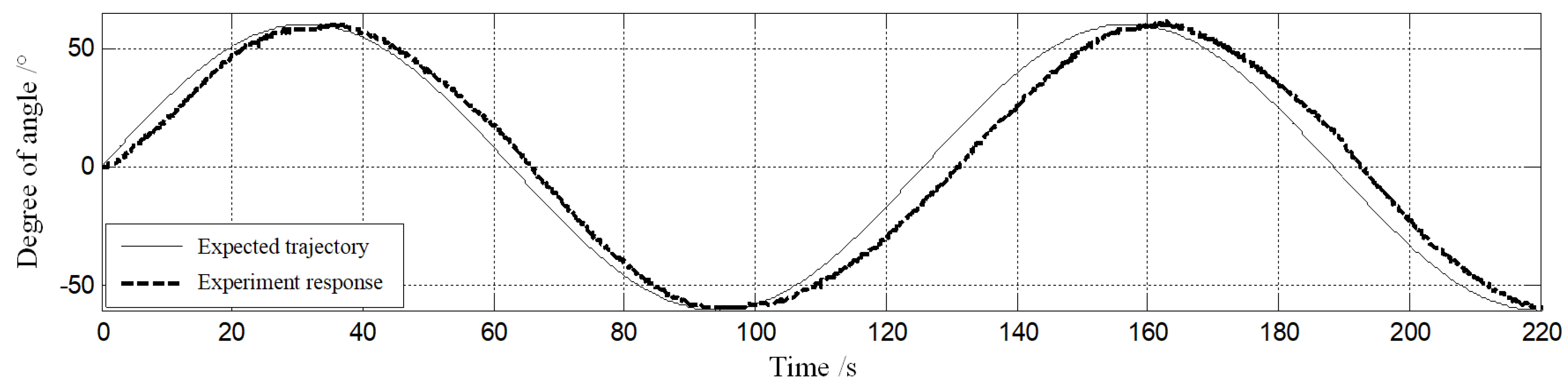
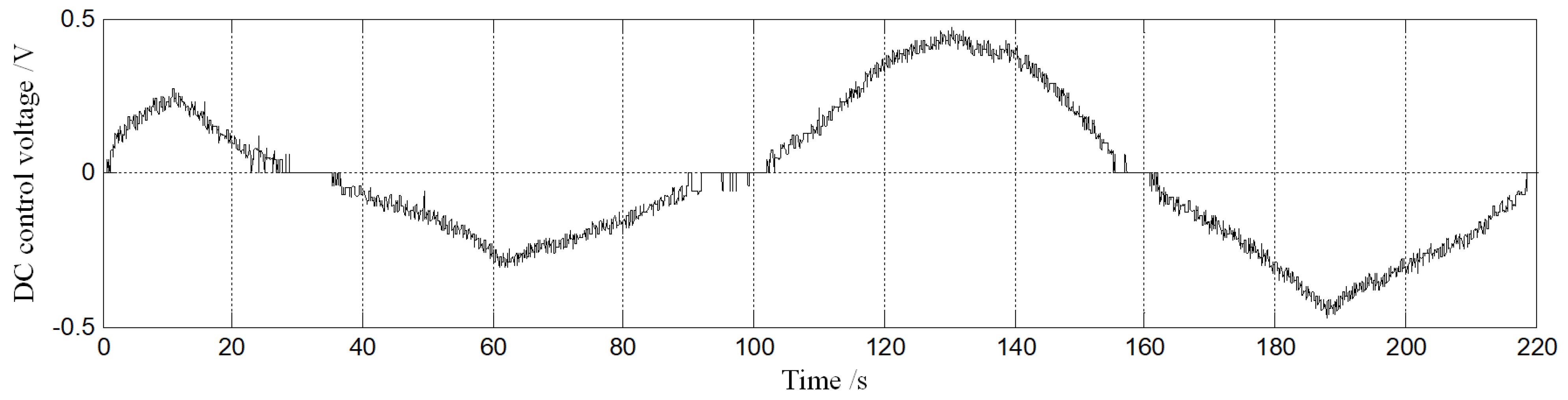
Section 5 aims through experimental validation to verify the accuracy of the model and effectiveness of the PID control algorithm. The conclusions end the paper in Section 6.

2. Design of Docking Device and Hydraulic Drive System

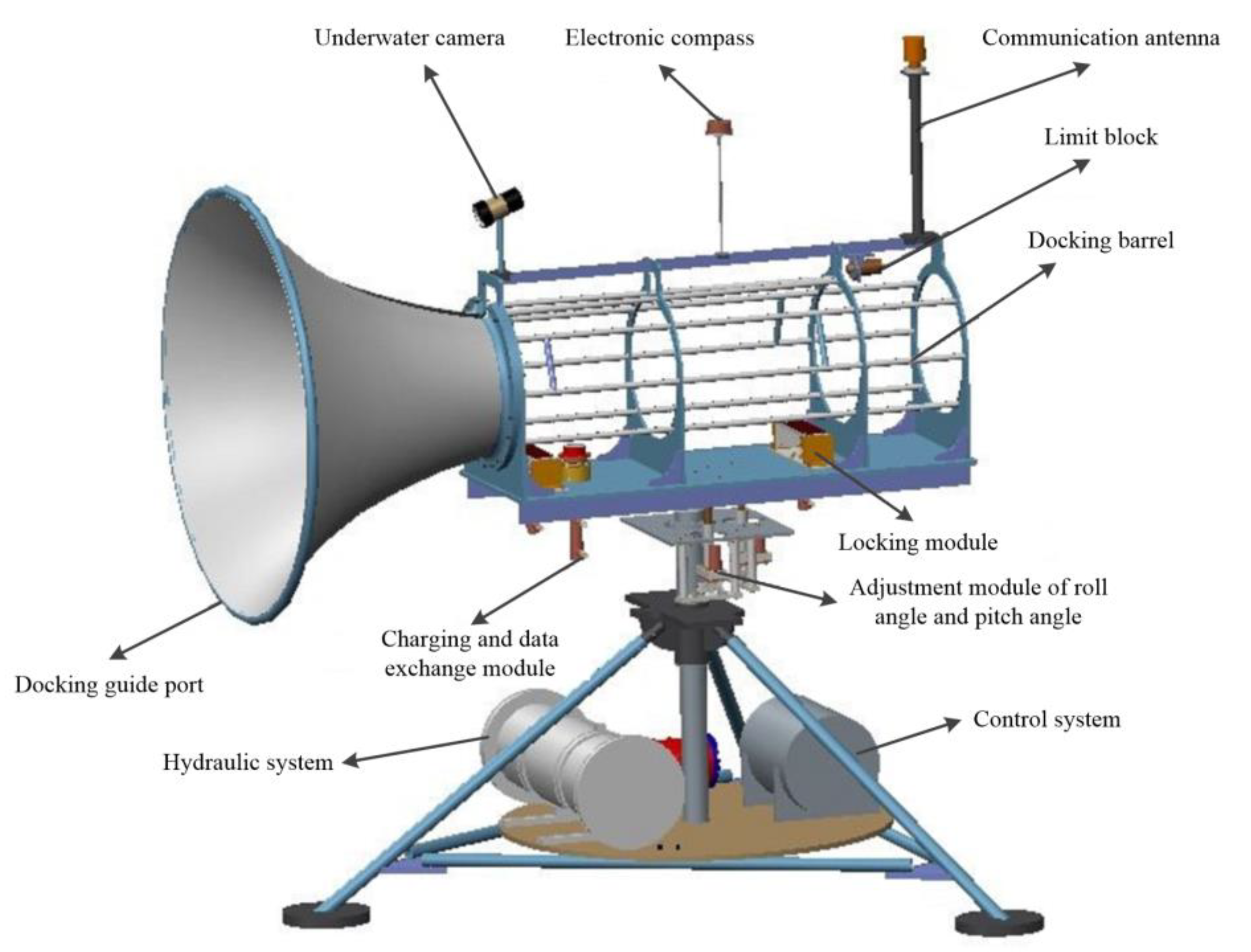
The designed multi-freedom AUV docking device is shown in Figure 1. The docking device has three bottom corners to ensure it can be located on the seafloor. The hydraulic system cabin and control system cabin are fixed on the disc at the bottom of the device. The docking device mainly consists of the guide port, docking barrel, underwater camera, communication antenna, electronic compass, charging and data exchange module, locking module, adjustment module of roll angle and pitch angle, and adjustment module of heading angle.
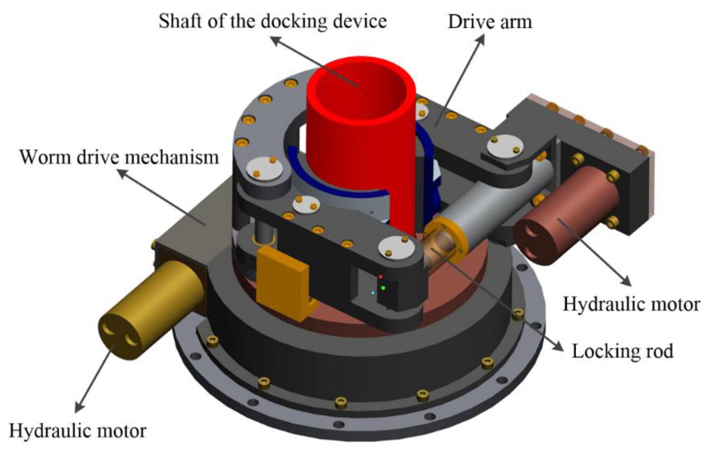
The adjustment module of heading angle is also located on the disc of the device, as shown in Figure 2, and it can lock the shaft of the docking device by one hydraulic motor driving the locking rod, and then drive the shaft to rotate by another hydraulic motor driving the worm gear mechanism, so as to achieve the heading angle adjustment of the guide port and the docking barrel. Owing to the self-locking characteristics of the worm gear mechanism, the module can achieve stable self-locking when the hydraulic motor does not rotate. The hydraulic cabin is connected with the executive components of each module through hydraulic pipelines and the control system cabin is connected with the hydraulic cabin, sensors, underwater camera, and other corresponding components through watertight cables. The height of the docking device is 3400 mm and the guide port is conical with a thickness of 8 mm. The maximum diameter of the guide port is 2000 mm and the diameter of the interface between the guide port and the docking barrel is 640 mm.
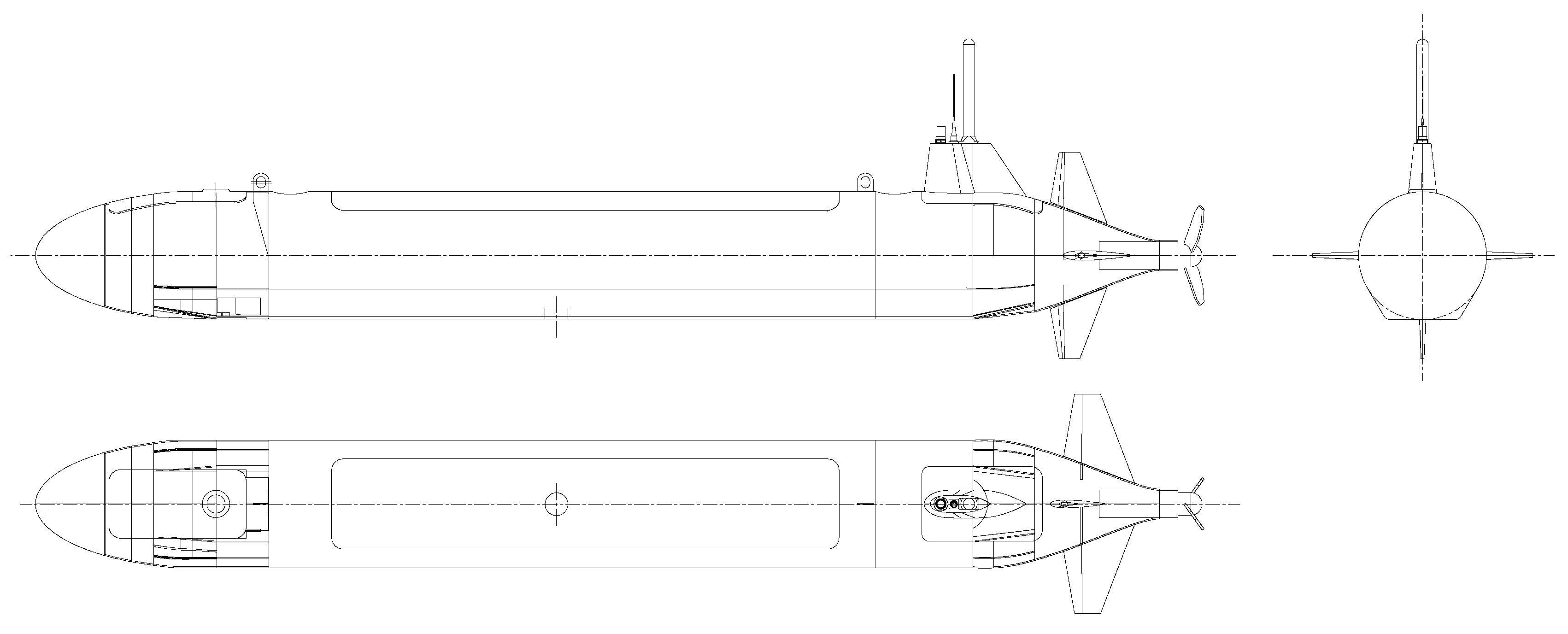
The three views of the target AUV to be docked are shown in Figure 3. The diameter of the AUV is 560 mm and the total length of the AUV is 5100 mm. The shell of the AUV is mainly made of fiber-reinforced plastic. The bottom of the AUV is flat and equipped with a charging interface, the upper of the AUV is equipped with a round lifting lug, and the tail is equipped with a communication antenna and a main propeller.
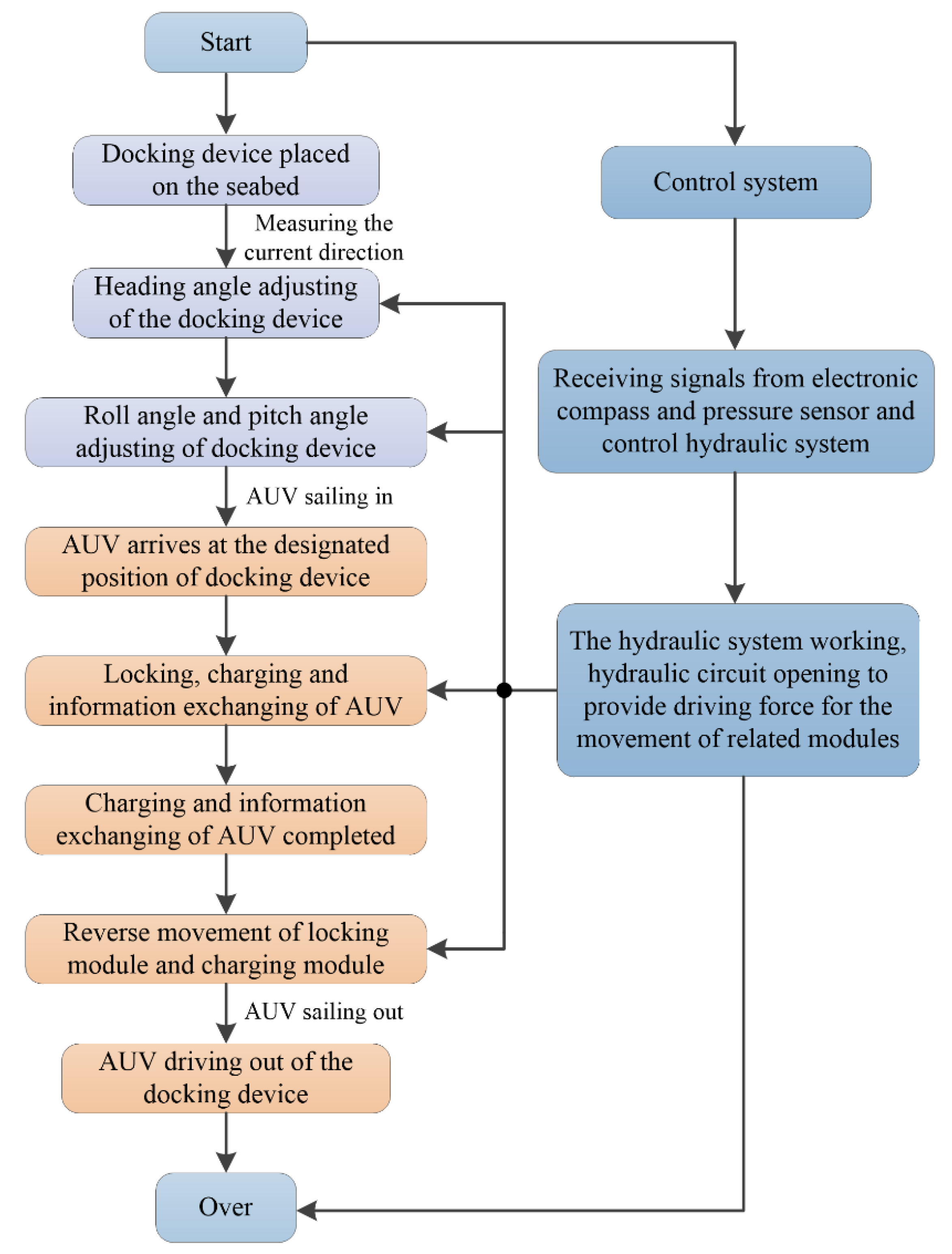
The docking flow chart of the AUV and the docking device is shown in Figure 4. After the docking device is placed on the seafloor, the current direction meter on the docking device will measure the current direction at this time and the electronic compass will measure the heading angle, roll angle, and pitch angle of the guide port and docking barrel. The heading angle of the guide port and docking barrel will be changed through the heading angle adjustment module to make it the same as the current flow direction angle. Then, the roll angle and pitch angle of the guide port and docking barrel will be adjusted through the adjustment module of roll angle and pitch angle so that the guide port and docking barrel are in the horizontal state. When the AUV drives into the docking barrel and reaches the designated position, the locking module first completes the locking of the AUV, and then the charging and data exchange module will charge the AUV and exchange data with it. Finally, the locking module, charging, and data exchange module move in the opposite direction, making the AUV in a non-locking state and the AUV exits the docking device under the force generated by the reverse movement of the propeller. The actions of the heading angle adjustment module, the adjustment module of roll angle and pitch angle, locking module, and charging and data exchange module are all realized by the movement of executive components such as hydraulic cylinder or hydraulic motor powered by the hydraulic system in the hydraulic cabin.
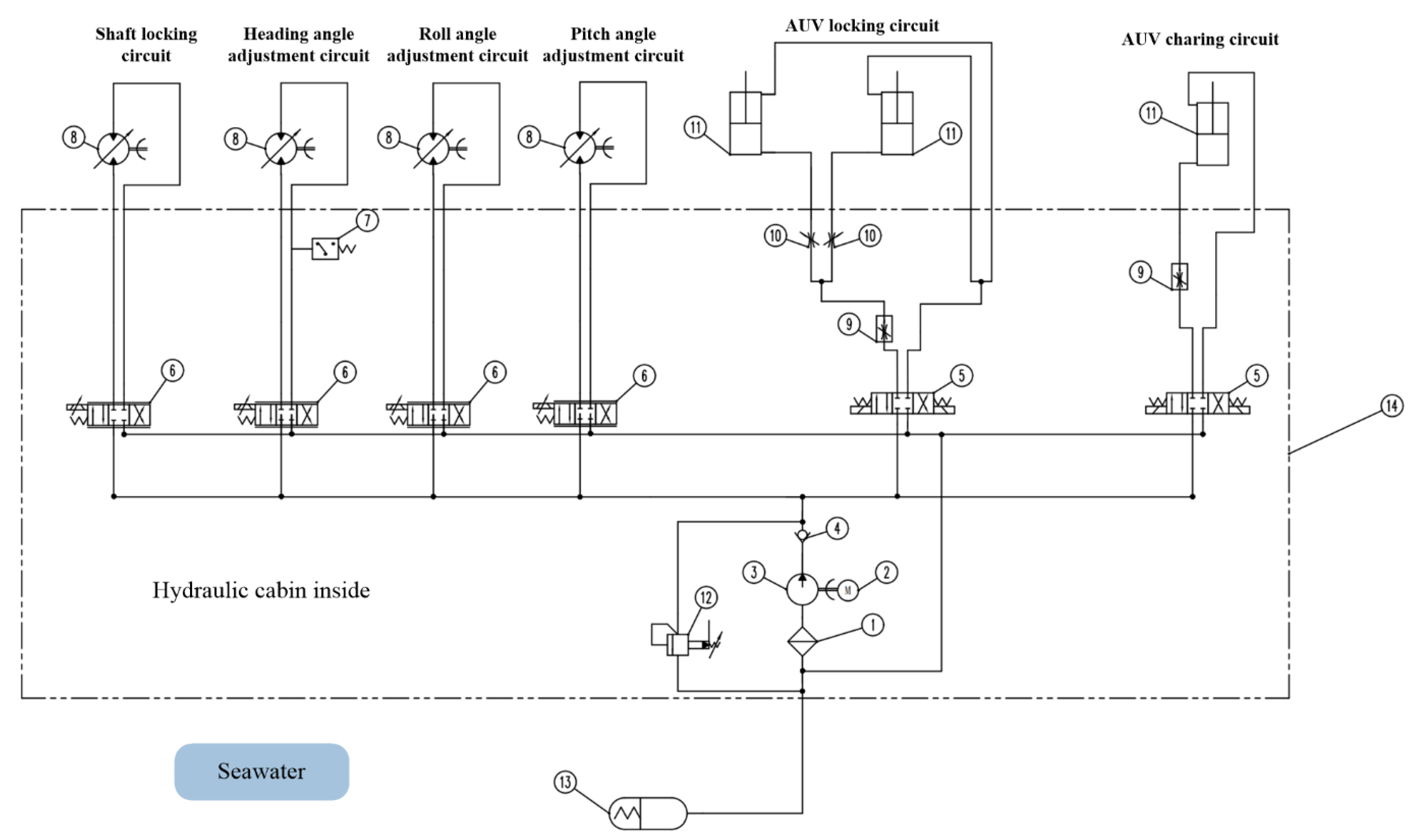
Figure 5 displays the schematic design of the hydraulic system of the docking device. The hydraulic system has the characteristics of small volume and large output power. Compared with using the motor drive in which we must solve the sealing problem of the motor in the deep-sea environment, the hydraulic cylinder and hydraulic motor of the hydraulic system designed in this paper are made of 316 stainless steel, which can withstand seawater corrosion for a long time and have high stability and low cost. The seawater pressure compensator of the hydraulic system can apply seawater pressure outside the hydraulic cabin to the pipelines of the hydraulic system, thus making the hydraulic system suitable for the deep-sea environment. The six independent hydraulic circuits can achieve shaft locking, heading angle adjustment, roll angle adjustment, pitch angle adjustment, AUV locking, and AUV charging, respectively. The six hydraulic circuits share a common hydraulic power source and each hydraulic circuit is controlled by its corresponding valve for opening, closing, direction changing, or flow speed control. The hydraulic pump, electric machinery, electromagnetic directional control valve, proportional servo valve, flow speed control valve, and some other components are sealed in the hydraulic system cabin and the hydraulic motor, hydraulic cylinder, and other actuating components can be resistant to seawater corrosion and directly exposed to seawater. The control system sends the control signal to the hydraulic cabin through a watertight cable, which can realize the start and stop of the electric machinery, the control of the proportional servo valve, and the electromagnetic directional control valve. Through the work of each circuit of the hydraulic system, a series of docking actions between the docking device and the AUV in Figure 4 can be achieved, thus completing the whole docking process.

3. Modeling of Heading Angle Adjustment Circuit of the Hydraulic System

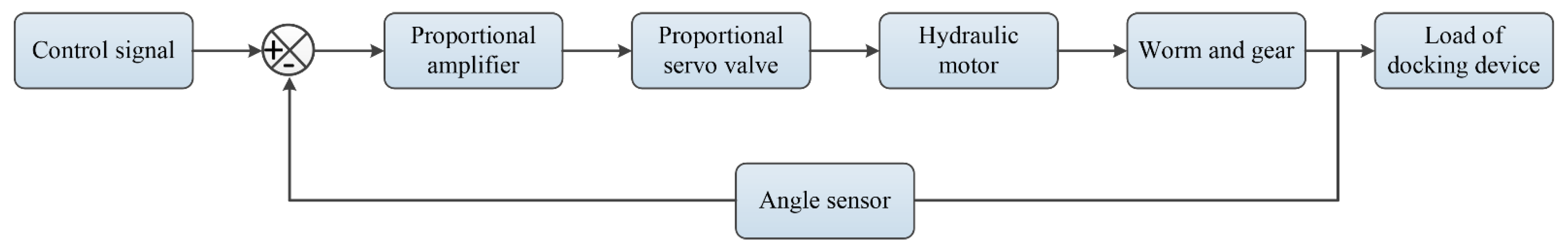
The heading angle adjustment, roll angle adjustment, and pitch angle adjustment of the AUV docking device can be achieved by the positive and negative rotation of the hydraulic motors controlled by the proportional servo valves. The heading angle adjustment circuit is composed of a proportional servo valve, a hydraulic motor, a worm gear mechanism, and an angle sensor. The control schematic diagram of the heading angle adjustment circuit is shown in Figure 6.
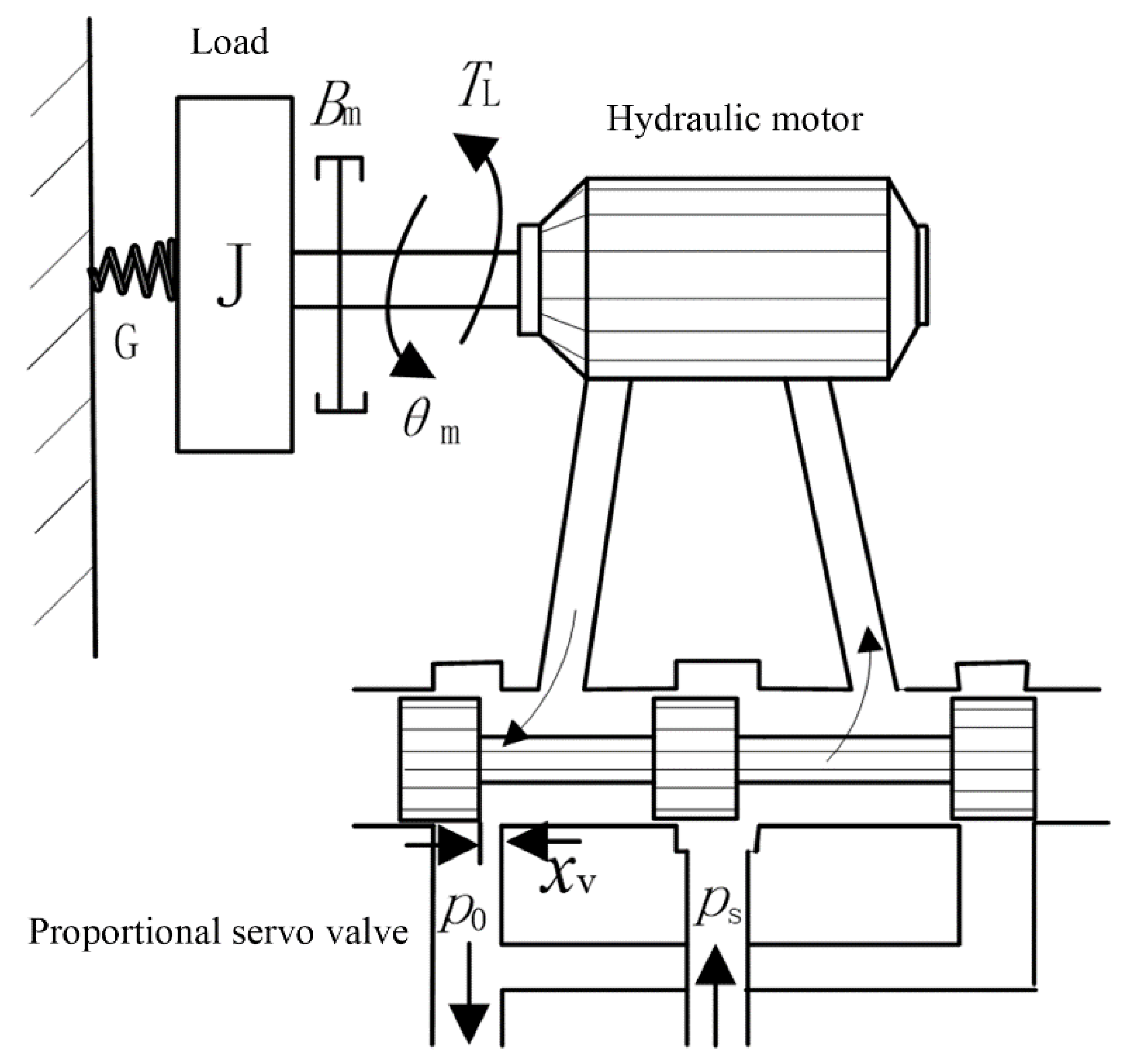
The schematic diagram of the power mechanism composed of a four-way proportional servo valve and a two-way hydraulic motor is shown in Figure 7. The linearized flow equation of the proportional servo valve can be expressed as follows:
Q L = K q x v K c p L
where Q L is the load flow, K q is the flow coefficient of the proportional servo valve, K c is the flow pressure coefficient of the proportional servo valve, and p L is the load pressure drop. Because of the compression of hydraulic oil, the flow Q 1 flowing into the motor is not equal to the flow Q 2 flowing out of the motor, that is Q 1 Q 2 . However, the compression amount of hydraulic oil is very small compared with Q 1 and Q 2 , so the load flow can be defined as Q L = ( Q 1 + Q 2 ) / 2 .
The hydraulic pipeline of the docking device is short, and the friction, fluid mass loss and dynamic pressure loss in the pipeline can be ignored. Moreover, the hydraulic motor has a short continuous working time and a small oil temperature rise, so the change of oil temperature and bulk modulus can also be ignored. The linearized flow equation of the motor can be expressed as follows:
Q L = D t M d θ M d t + C t M p L + V t 4 β e d p L d t
where D t M is the theoretical displacement of the hydraulic motor; θ M is the rotation angle of the hydraulic motor shaft; β e is the elastic modulus of the effective volume, β e = 700   Mpa ; V t is the volume of oil inlet chamber of the hydraulic motor (including valve, pipeline and oil inlet chamber); C t M is the total leakage coefficient of the hydraulic motor C t M = C i M + C e M / 2 ; C i M is the internal leakage coefficient of the hydraulic motor; and C e M is the external leakage coefficient of the hydraulic motor.
The torque balance equation of the hydraulic motor is as follows:
T g = D t M p L = J d 2 θ M d t 2 + B M d θ M d t + G θ M + T L
where T g is the theoretical torque of the hydraulic motor, J is the total inertia of the hydraulic motor and the load, θ M is the rotation angle of the hydraulic motor shaft, B M is the total viscous damping coefficient of the hydraulic motor and the load, G is the torsional spring stiffness of the load, and T L is the external load force acting on the motor.
The following equation be obtained after the Laplacian transformation and combination of Equations (1)–(3):
θ M = K q D M X v K c e D M 2 ( 1 + V t 4 β e K c e s ) T L V t J 4 β e D M 2 s 3 + ( K c e J D M 2 + B M V t 4 β e D M 2 ) s 2 + ( 1 + B M K c e D M 2 + K V t 4 β e D M 2 ) s + K c e G D M 2
where K c e is the total flow-pressure coefficient, K c e = K c + C t M .
Equation (4) shows the response characteristics of the hydraulic motor rotation angle to the valve input displacement and load force and takes into account the influence of the system’s physical characteristics such as inertial load, elastic load, viscous friction load, hydraulic motor leakage, and oil compressibility on the motor speed. The load of the docking device can be considered as an inelastic load, that is G = 0. In addition, the damping coefficient D M 2 / K c e is much larger than BM, so B M K c e / D M 2 1 . In order to study the control characteristics of the system, the load is considered as the interference term in this paper, so the transfer function of motor shaft rotation angle to valve displacement without load can be obtained as follows:
G M ( s ) = θ M X v = K q / D M s ( s 2 ω h 2 + 2 ξ h ω h s + 1 )
where ω h is the natural frequency of the system, ω h = 4 β e D M 2 V t J ; ξ h is the damping of the system, ξ h = K c e D M β e J V t + B M 4 D M V t β e J ; and, in general, B M is very small, so ξ h can be simplified as ξ h = K c e D M β e J V t .
The hydraulic system parameters in Equation (5) are listed in Table 1.
In practical engineering, generally ξ h 0.1 ~ 0.2 , and in this paper we set ξ h = 0.1 . Finally, the transfer function of the hydraulic motor can be obtained as follows:
G M ( s ) = K q / D M s ( s 2 38.2 2 + 2 × 0.1 38.2 s + 1 )
Equation (6) is composed of a proportional component, an integral component, and a shock component, and it can be concluded that it is a type I system.
In addition to the proportional servo valve and the hydraulic motor, mathematical models of other components in Figure 6 also need to be established. The proportional amplifier is used together with the proportional servo valve to convert the input voltage signal into a current signal and output it to the proportional servo valve.
In this paper, the rated input voltage of the proportional amplifier is U0 = 10 V and the rated output current is I0 = 3 A, then the proportional amplification gain is as follows:
K a = U 0 / I 0 = 3 10 = 0.3   A / V
The transfer function of the proportional servo valve is a typical second-order model, which could be expressed as follows:
K x v G s v ( s ) = Q ( s ) / I ( s ) = K x v s 2 ω s v 2 + 2 ζ s v ω s v s + 1
where K x v is the flow gain of the proportional servo valve, K x v = Δ q n Δ p / Δ p n / I ; Δ q n is the flow gain under the specified valve port pressure drop of the proportional servo valve, Δ q n = 25 L/min; Δ p is the actual valve port pressure drop of the proportional servo valve, Δ p = 3.7 MPa; Δ p n is the specified valve port pressure drop for the proportional servo valve, Δ p n = 10 MPa; G s v ( s ) is the transfer function of the proportional servo valve; Q is the flow of proportional servo valve; I is the input current of the proportional servo valve; ω s v is the natural frequency of the proportional servo valve, ω s v = 502.4 Hz ; and ζ s v is the damping ratio of the proportional servo valve, with a value range of 0.5~0.7.
Therefore, Equation (8) can be rewritten as follows:
K x v G s v ( s ) = Q ( s ) / I ( s ) = 5 × 10 3 s 2 502.4 2 + 1.2 502.4 s + 1
The deviation signal input by the proportional amplifier is as follows:
θ e = θ r θ f
where θ r is the control voltage signal and θ f is the feedback voltage signal.
The feedback signal of the angle sensor is as follows:
θ f = K θ θ
where K θ is the gain of the angle sensor, K θ = 1.44 V/rad.
The input current equation of the proportional servo valve is as follows:
Δ I = K a θ e
The speed reduction ratio of the worm gear mechanism is i = 80.
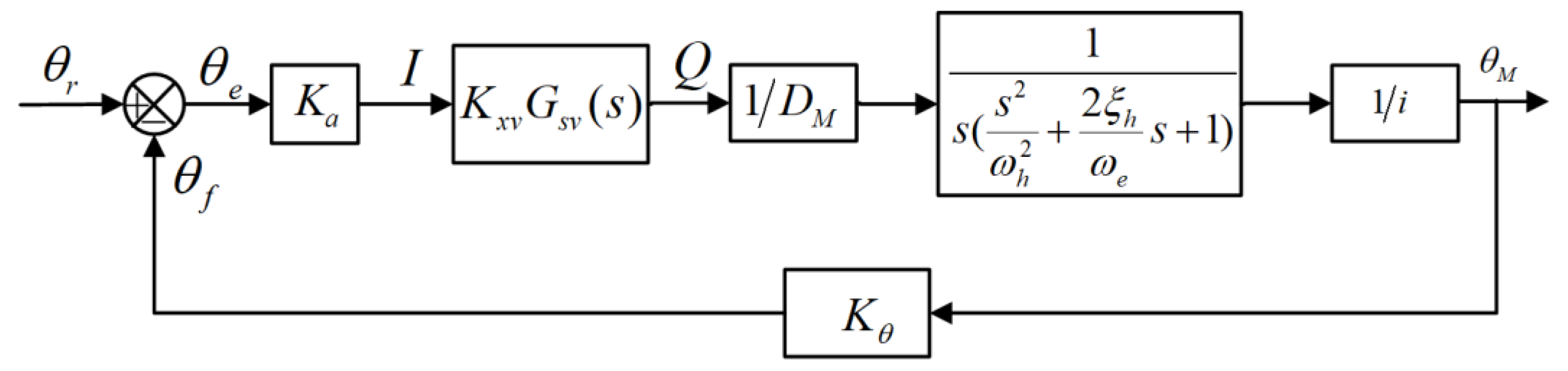
The angle control block diagram of the heading angle adjustment circuit can be obtained by combining Equations (5), (7), (8) and (10)–(12), as shown in Figure 8.
Taking the load as interference, when the external load torque T L is zero, the block diagram of the system can be simplified as Figure 9.
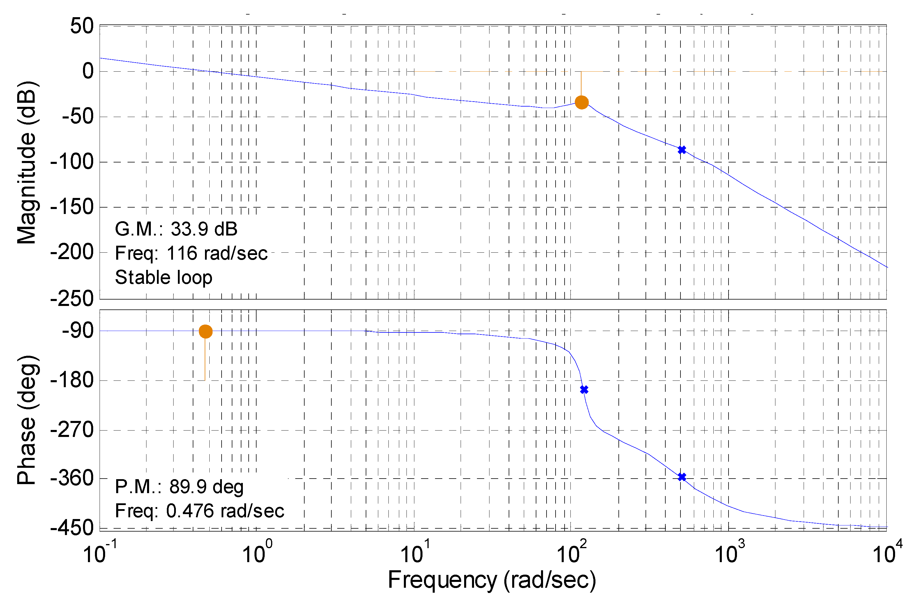
Therefore, the open-loop transfer function of the output angle θ M to the input signal θ r of the system is as follows:
G K ( s ) = K a K x v G s v ( s ) 1 D M i K θ s ( s 2 ω 0 2 + 2 ζ 0 ω 0 s + 1 ) = 1.69 s ( s 2 38.2 2 + 0.2 38.2 s + 1 ) ( s 2 502.4 2 + 2 × 0.6 502.4 s + 1 )

4. Simulation of Dynamic Characteristics of the Hydraulic Control System

The open-loop Bode diagram of Equation (13) was calculated using Matlab, as shown in Figure 10. It can be seen from Figure 10 that the phase margin and amplitude margin of the system are 33.9 db and 89.9 db, respectively, so the system meets the stability requirements. The open-loop crossing frequency of the system is 0.476 rad/s, which is much lower than the natural frequency of the hydraulic actuator (38.2 rad/s) and the natural frequency of the proportional servo valve (502.4 rad/s). Therefore, the system bandwidth should be increased to speed up the response of the system. The phase margin of the system is 89.9 rad/s, which is large and has good stability. However, the transient response to interference is slow and the acceleration error of the system will also be large.
In order to ensure the stability of the system, reduce the steady-state error, and improve the response speed, the PID controller was used to improve the dynamic response performance of the system. The module block diagram of the heading angle adjustment circuit was established through Simulink in Matlab, as shown in Figure 11. The PID parameters were optimized using the Simulink Design Optimization tool and the toolbox can select the best controller parameters that meet the requirements through continuous simulation. Finally, we obtained K p = 9.5, K i = 0.03, and K d = 0.01.
Figure 12 shows the response of the system to the unit step signal with and without the optimized PID control algorithm and the response curve under the pulse interference. The amplitude of the applied pulse interference is 10,000 and the duration time is 0.1 s. It can be seen from Figure 12 that the system with optimized PID has no overshoot, and the time to reach stability is about 1 s. Compared with the system without PID, its response time to the unit step signal is reduced by 9 s. The maximum deviation of the system is about 0.1 at 12.5 s and it takes less than 2 s for the system to return to the stable value at nearly 14 s. Compared with the system without PID, the deviation amplitude of the system from the target value under pulse signal interference is reduced from 0.4 to 0.1, the deviation amplitude is reduced by 75%, the time to recover to the stable value is reduced from 8 s to 2 s, and the time is shortened by 75%. The anti-interference ability of the system is significantly improved after the optimized PID control algorithm is applied.

5. Experimental Validation

The experiment of the heading angle adjustment of the docking device was conducted in a water pool to validate the accuracy of the modeling and the effectiveness of the control algorithm. The physical experiment diagram of the docking device in the water pool is shown in Figure 13. The three feet of the docking device are located at the bottom of the pool and the docking device is completely submerged in the water.
In order to test the tracking performance of the system, a sine signal was input to the system, and the equation of the signal is y = 60 sin (0.05 t). The response curve and control voltage curve of the system are shown in Figure 14 and Figure 15, respectively. It can be seen from Figure 14 and Figure 15 that, in the first cycle, the maximum positive error is 5° (at 10 s), the corresponding control voltage is 0.25 V, the maximum negative error is 5° (at 61 s), and the corresponding control voltage is −0.3 V. In the second cycle, the tracking error of the system increases. The maximum positive error is 10° (at 130 s), the corresponding control voltage is 0.45 V, the maximum positive error is 10° (at 175 s), and the corresponding control voltage is −0.45 V. The maximum error of the angle tracking of the system is 8.3% under the excitation of the above sinusoidal signal. As a whole, the angle tracking error of the system is always small, which shows that the model of the hydraulic circuit and the control system established in this paper has achieved high accuracy, and the accuracy of modeling and the effectiveness of the control algorithm were validated. The performance of the docking device and the effectiveness of the control algorithm in the deep-sea environment need to be further verified.

6. Conclusions

In this paper, a funnel-shaped underwater docking device with multi-degree freedom based on a submarine platform was designed. In order to realize the timely adjustment of the heading angle, pitch angle, and roll angle of the docking device, a set of underwater hydraulic system was developed as the power source to drive the corresponding hydraulic cylinders, hydraulic motors, and other executive components. The model of the heading angle adjustment circuit of the hydraulic system was established and the open-loop transfer function of the circuit was derived. In order to ensure the stability of the system, reduce the steady-state error and improve the response speed, the optimized PID controller was employed to increase the system’s dynamic response performance. The simulation results demonstrate that the anti-interference ability of the system has been greatly increased as the optimized PID control algorithm is applied. To validate the accuracy of the modeling and the effectiveness of the control algorithm, the experiment of the heading angle adjustment of the docking device was carried out in a water pool. The maximum error of the angle tracking of the system is 8.3% under the excitation of the sinusoidal signal. It was concluded from the experiment results that the angle tracking error of the system is small, showing that the model of the hydraulic circuit and the control system established has achieved high accuracy and the control algorithm is effective.
In future research, we will focus on the research of the collision between the AUV and the docking device during the docking process and the AUV docking control strategy, in order to achieve more accurate underwater docking.

Author Contributions

Conceptualization, X.D. and C.Z.; software, B.Z.; validation, X.D. and C.Z.; formal analysis, X.D.; investigation, X.D. and B.Z.; writing—original draft preparation, X.D. and B.Z.; writing—review and editing, M.S. and C.Z. All authors have read and agreed to the published version of the manuscript.

Funding

This research was funded by the National Key Research and Development Program of China (grant number 2019YFB2006402) and Scientific Research Foundation for High-level Talents of Nanjing Institute of Technology (grant number YKJ202102).

Institutional Review Board Statement

Not applicable.

Informed Consent Statement

Not applicable.

Data Availability Statement

Not applicable.

Conflicts of Interest

The authors declare no conflict of interest.

References

  1. Stokey, R.; Allen, B.; Austin, T.; Goldsborough, R.; Forrester, N.; Purcell, M.; Von Alt, C. Enabling technologies for REMUS docking: An integral component of an autonomous ocean-sampling network. IEEE J. Ocean. Eng. 2001, 26, 487–497. [Google Scholar] [CrossRef]
  2. Stokey, R.; Purcell, M.; Forrester, N.; Austin, T.; Goldsborough, R.; Allen, B.; von Alt, C. A docking system for REMUS, an autonomous underwater vehicle. In Proceedings of the Oceans’ 97. MTS/IEEE Conference Proceedings, Halifax, NS, Canada, 6–9 October 2017; Volume 2, pp. 1132–1136. [Google Scholar]
  3. Feezor, M.D.; Sorrell, F.Y.; Blankinship, P.R.; Bellingham, J.G. Autonomous underwater vehicle homing/docking via electromagnetic guidance. IEEE J. Ocean. Eng. 2001, 26, 515–521. [Google Scholar] [CrossRef]
  4. Cowen, S.; Briest, S.; Dombrowski, J. Underwater docking of autonomous undersea vehicles using optical terminal guidance. In Proceedings of the Oceans’ 97. MTS/IEEE Conference Proceedings, Halifax, NS, Canada, 6–9 October 2017; Volume 2, pp. 1143–1147. [Google Scholar]
  5. Singh, H.; Bellingham, J.G.; Hover, F.; Lemer, S.; Moran, B.A.; Von der Heydt, K.; Yoerger, D. Docking for an autonomous ocean sampling network. IEEE J. Ocean. Eng. 2001, 26, 498–514. [Google Scholar] [CrossRef]
  6. McEwen, R.S.; Hobson, B.W.; McBride, L.; Bellingham, J.G. Docking control system for a 54-cm-diameter (21-in) AUV. IEEE J. Ocean. Eng. 2008, 33, 550–562. [Google Scholar] [CrossRef]
  7. Jantapremjit, P.; Wilson, P.A. Optimal control and guidance for homing and docking tasks using an autonomous underwater vehicle. In Proceedings of the 2007 International Conference on Mechatronics and Automation, Harbin, China, 5–9 August 2007; pp. 243–248. [Google Scholar]
  8. Jantapremjit, P.; Wilson, P.A. Guidance-control based path following for homing and docking using an autonomous underwater vehicle. In Proceedings of the OCEANS 2008-MTS/IEEE Kobe Techno-Ocean, Kobe, Japan, 8–11 April 2008; pp. 1–6. [Google Scholar]
  9. Park, J.Y.; Jun, B.H.; Lee, P.M.; Oh, J. Experiments on vision guided docking of an autonomous underwater vehicle using one camera. Ocean. Eng. 2009, 36, 48–61. [Google Scholar] [CrossRef]
  10. Park, J.Y.; Jun, B.H.; Lee, P.M.; Lim, Y.K.; Oh, J.H. Docking problem and guidance laws considering drift for an underactuated AUV. In Proceedings of the OCEANS 2011 IEEE-Spain, Santander, Spain, 6–9 June 2011; pp. 1–7. [Google Scholar]
  11. Raspante, F. Underwater mobile docking of autonomous underwater vehicles. In Proceedings of the 2012 Oceans, Hampton Roads, VA, USA, 14–19 October 2012; pp. 14–19. [Google Scholar]
  12. Rigaud, V.; Nicolas-Meunier, B. From manned to autonomous and hybrid underwater systems. In Proceedings of the 2015 IEEE Underwater Technology (UT), Chennai, India, 23–25 February 2015; pp. 1–10. [Google Scholar]
  13. Batista, P.; Silvestre, C.; Oliveira, P. A two-step control approach for docking of autonomous underwater vehicles. Int. J. Robust Nonlinear Control 2015, 25, 1528–1547. [Google Scholar] [CrossRef]
  14. Ferreira, B.M.; Matos, A.C.; Cruz, N.A.; Moreira, A.P. Homing a robot with range-only measurements under unknown drifts. Robot. Auton. Syst. 2015, 67, 3–13. [Google Scholar] [CrossRef]
  15. Li, Y.; Jiang, Y.; Cao, J.; Wang, B.; Li, Y. AUV docking experiments based on vision positioning using two cameras. Ocean Eng. 2015, 110, 163–173. [Google Scholar] [CrossRef]
  16. Yang, C.; Peng, S.; Fan, S.; Zhang, S.; Wang, P.; Chen, Y. Study on docking guidance algorithm for hybrid underwater glider in currents. Ocean Eng. 2016, 125, 170–181. [Google Scholar] [CrossRef]
  17. Sans-Muntadas, A.; Pettersen, K.Y.; Brekke, E.; Henriksen, V.F. A hybrid approach to underwater docking of AUVs with cross-current. In Proceedings of the OCEANS 2016 MTS/IEEE Monterey, Monterey, CA, USA, 19–23 September 2016; pp. 1–7. [Google Scholar]
  18. Piskura, J.C.; Purcell, M.; Stokey, R.; Austin, T.; Tebo, D.; Christensen, R.; Jaffre, F. Development of a robust Line Capture, Line Recovery (LCLR) technology for autonomous docking of AUVs. In Proceedings of the OCEANS 2016 MTS/IEEE Monterey, Monterey, CA, USA, 19–23 September 2016; pp. 1–5. [Google Scholar]
  19. Sarda, E.I.; Dhanak, M.R. Launch and recovery of an autonomous underwater vehicle from a station-keeping unmanned surface vehicle. IEEE J. Ocean. Eng. 2018, 44, 290–299. [Google Scholar] [CrossRef]
  20. Hurtos, N.; Mallios, A.; Palomeras, N.; Bosch, J.; Vallicrosa, G.; Vidal, E.; Ribas, D.; Gracias, N.; Carreras, M.; Ridao, P. LOON-DOCK: AUV homing and docking for high-bandwidth data transmission. In Proceedings of the OCEANS 2017-Aberdeen, Aberdeen, UK, 19–22 June 2017; pp. 1–7. [Google Scholar]
  21. Palomeras, N.; Vallicrosa, G.; Mallios, A.; Bosch, J.; Vidal, E.; Hurtos, N.; Carreras, M.; Ridao, P. AUV homing and docking for remote operations. Ocean Eng. 2018, 154, 106–120. [Google Scholar] [CrossRef]
  22. Zuo, M.; Wang, G.; Xiao, Y.; Xiang, G. A unified approach for underwater homing and docking of over-actuated AUV. J. Mar. Sci. Eng. 2021, 9, 884. [Google Scholar] [CrossRef]
  23. Lin, R.; Zhao, Y.; Li, D.; Lin, M.; Yang, C. Underwater Electromagnetic Guidance Based on the Magnetic Dipole Model Applied in AUV Terminal Docking. J. Mar. Sci. Eng. 2022, 10, 995. [Google Scholar] [CrossRef]
  24. Lin, M.; Lin, R.; Yang, C.; Li, D.; Zhang, Z.; Zhao, Y.; Ding, W. Docking to an underwater suspended charging station: Systematic design and experimental tests. Ocean Eng. 2022, 249, 110766. [Google Scholar] [CrossRef]
  25. Anderlini, E.; Parker, G.G.; Thomas, G. Docking control of an autonomous underwater vehicle using reinforcement learning. Appl. Sci. 2019, 9, 3456. [Google Scholar] [CrossRef] [Green Version]
  26. Palomeras, N.; Peñalver, A.; Massot-Campos, M.; Negre, P.L.; Fernández, J.J.; Ridao, P.; Sanz, P.J.; Oliver-Codina, G. I-AUV docking and panel intervention at sea. Sensors 2016, 16, 1673. [Google Scholar] [CrossRef] [PubMed]
  27. Zhang, T.; Li, D.; Yang, C. Study on impact process of AUV underwater docking with a cone-shaped dock. Ocean Eng. 2017, 130, 176–187. [Google Scholar] [CrossRef]
  28. Li, D.J.; Chen, Y.H.; Shi, J.G.; Yang, C.J. Autonomous underwater vehicle docking system for cabled ocean observatory network. Ocean Eng. 2015, 109, 127–134. [Google Scholar] [CrossRef]
  29. Roy, S.; Shome, S.N.; Nandy, S.; Ray, R.; Kumar, V. Trajectory following control of AUV: A robust approach. J. Inst. Eng. (India) Ser. C 2013, 94, 253–265. [Google Scholar] [CrossRef]
  30. Roy, S.; Nandy, S.; Shome, S.N.; Ray, R. Robust position control of an autonomous underwater vehicle: A comparative study. In Proceedings of the 2013 IEEE International Conference on Automation Science and Engineering (CASE), Madison, WI, USA, 17–20 August 2013; pp. 1002–1007. [Google Scholar]
Figure 1. Designed AUV docking device with multi-degree freedom.
Jmse 10 01790 g001
Figure 2. Adjustment module of the heading angle.
Jmse 10 01790 g002
Figure 3. Three views of the target AUV to be docked.
Jmse 10 01790 g003
Figure 4. Docking flow chart of the AUV and the designed docking device.
Jmse 10 01790 g004
Figure 5. Designed underwater hydraulic system of the AUV docking device: 1. filter; 2. electric machinery; 3. hydraulic pump; 4. unilateral valve; 5. electromagnetic directional control valve; 6. proportional servo valve; 7. pressure sensor; 8. hydraulic motor; 9. flow speed control valve; 10. throttle valve; 11. hydraulic cylinder; 12. relief valve; 13. seawater pressure compensator; 14. hydraulic system cabin.
Jmse 10 01790 g005
Figure 6. Control schematic diagram of heading angle adjustment circuit.
Jmse 10 01790 g006
Figure 7. Schematic diagram of the valve-controlled hydraulic motor.
Jmse 10 01790 g007
Figure 8. The angle control block diagram of the heading angle adjustment circuit.
Jmse 10 01790 g008
Figure 9. Simplified angle control block diagram of the heading angle adjustment circuit.
Jmse 10 01790 g009
Figure 10. Open-loop Bode diagram of the established model.
Jmse 10 01790 g010
Figure 11. Module block diagram of the heading angle adjustment circuit.
Jmse 10 01790 g011
Figure 12. Response of the system to the unit step signal and response curve under the pulse interference: (a) unit step response of the system with optimized PID; (b) unit step response of the system without PID; (c) response curve of the system with optimized PID under pulse interference; (d) response curve of the system without PID under pulse interference.
Jmse 10 01790 g012
Figure 13. Physical experiment diagram of the docking device in the water pool.
Jmse 10 01790 g013
Figure 14. The expected trajectory and experiment response of the system.
Jmse 10 01790 g014
Figure 15. Control voltage of the proportional servo valve.
Jmse 10 01790 g015
Table 1. Parameters of the hydraulic system.
D M V t J β e K c e
16 mL/r1.5 × 10−4 m30.083 kg·m/s2700 MPa5.1 × 10−11 m5/N·s
Publisher’s Note: MDPI stays neutral with regard to jurisdictional claims in published maps and institutional affiliations.

