1. Introduction
STORMTOOLS Coastal Environmental Risk Index (CERI) [
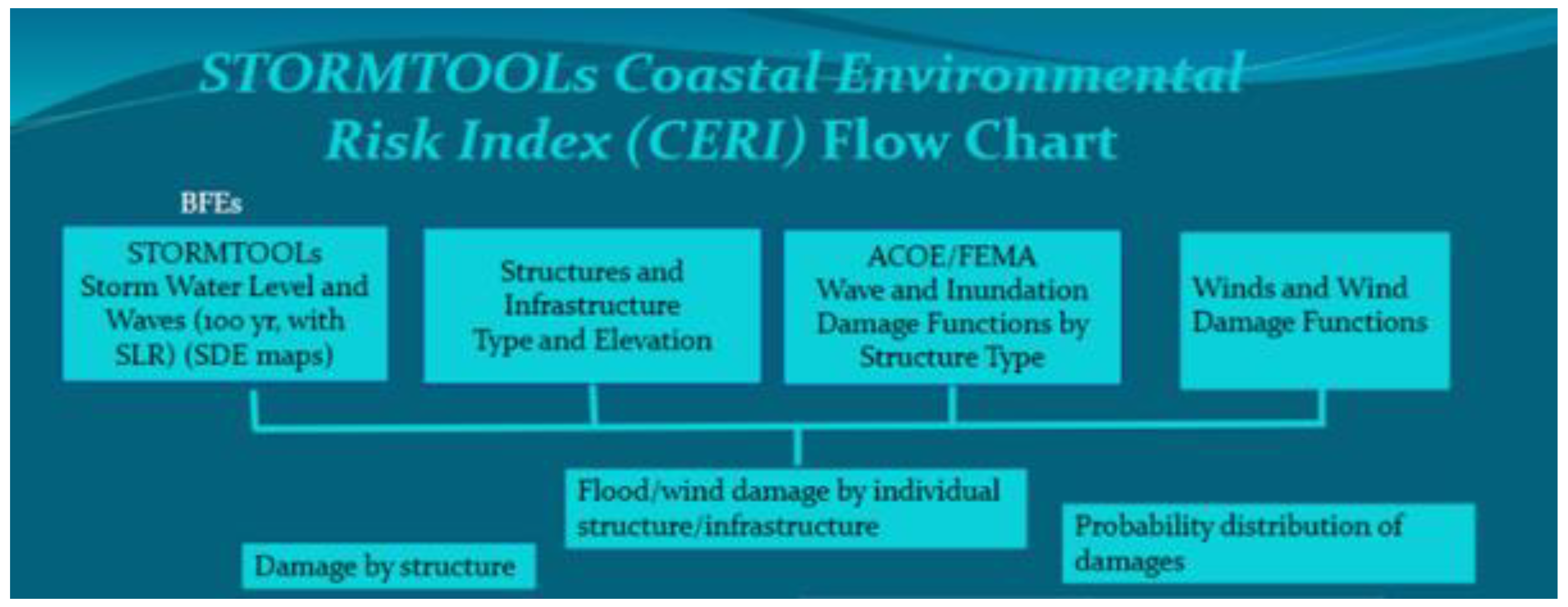
1] was originally developed in 2016 to estimate the damage from coastal flooding on structures and infrastructure. A flow chart for CERI is shown in
Figure 1 [
1]. The basic building blocks are (a) estimates of the storm surge and waves, expressed in terms of the Base Flood Elevation (BFE) (also called STORMTOOLS Design Elevation (SDE)), including the effects of sea level rise (SLR) [
2], (b) details on the structure or infrastructure (structure type, elevation, etc.) at risk, and (c) damage functions, by structure type, based on Army Corp of Engineering (ACOE) or Federal Emergency Management Agency (FEMA) data. The output is provided in terms of the damage to individual structures or distribution of damage to all structures impacted. The framework can be extended to estimate wind damage as well. CERI has been widely applied to structures in coastal areas of RI, including the southern RI shoreline [
1,
3] and selected locations in Narragansett Bay [
1], with a primary focus on residential and commercial structures. The applications to the southern RI shoreline have also included consideration of the erosion of the shoreline in response to coastal flooding events [
2]. The analyses have also included the impact of sea level rise (SLR). CERI and SDE maps are available via the STORMTOOLS GIS Hub (STORMTOOLS Home (arcgis.com), accessed on 1 September 2022) for coastal areas in the state. To help make the results of CERI more widely available a mobile phone
app has been designed to allow access to CERI estimates of damage [
4].
The present study, undertaken as part of the senior capstone design project in Ocean Engineering (OCE) at the University of RI (URI), Narragansett, RI in the academic year 2021–2022 [
5] looked at flood damage along the Warren River, RI commercial waterfront. In this effort CERI was extended to assess the impact of flooding on wastewater treatment facility (WWTF) and specifically the treatment plant for the Town of Warren located along the Warren River in Narragansett Bay (
Figure 2). The FEMA HAZUS damage functions for wastewater treatment facilities (WWTF) [
5,
6] were integrated into CERI to estimate damage with the SDE maps [
2] providing the estimates of flooding on water level and wave conditions at the locations of interest (BFEs). To validate the methodology, and specifically the use of the FEMA HAZUS WWTF damage curves, CERI was applied to predict the impact of the March/April 2010 flooding event (500 yr event) on three treatment plants located on the Pawtuxet River (Cranston, Warwick, and West Warwick). This flooding event was caused by intense rainfall. The three WWTF impacted are located above the head of the tide. Model predictions of damage were compared to observations by the plant operators during the event.
Section 2 provides a brief overview of methodology of how CERI has been extended to address the damage to WWTF from flooding,
Section 3 then shows the application of CERI to the Warren, RI WWTF investigation and the impact on each component of the system. Simulations were performed for the 100 yr storm, including the impact of sea level rise (SLR).
Section 4 summarizes validation of the CERI with FEMA HAZUS WWTF damage curves by comparing model predictions to observations for the three facilities damaged during the March/April 2010 flooding event. Discussion of the results are included
Section 5. Summary and conclusions are presented in
Section 6.
2. Methodology
In the present study, the CERI framework (
Figure 1) was extended to address the impact of flooding on WWTF. This extension was straightforward, where the ACOE/FEMA Wave and Inundation Damage Functions for structures (residential and commercial) were replaced by damage functions for WWTF. In the present study, the FEMA HAZUS damage curves [
6,
7] were employed. The damage curves are provided as a function of the inundation level for the entire treatment facility and include estimates of the average and upper and lower bounds. The damage curves are independent of the design flow of the treatment facility. The documentation on the source of the damage curves in the FEMA HAZUS manual is very limited and little information could be found in the literature. In applying the method, within the CERI framework, it was assumed that damage to each major component of the facility (e.g., primary settling tanks, headworks, chlorination tanks, secondary clarifiers, operations building, and aeration and reactor tanks) would be assessed. The estimated percent damage would then be averaged across all components of the facility to arrive at a damage estimate for the facility. It was assumed that the BFE values could be used as proxy for the inundation levels since they reflect the combined effects of surge and waves. The results of this effort are provided in
Section 3.
Given the lack of documentation of the source of data for the FEMA HAZUS damage curve or their validation against actual flooding events [
6,
7], an effort was undertaken to validate the curves by applying CERI to assess the damage to the Warwick, West Warwick, and Cranston WWTFs from the April/May 2010 flood event on the Pawtuxet River (500 yr event). The event was from rainfall induced riverine flooding. The facilities are located well above the head of the tide. The inundation levels were fully documented from the facility operators and US Geological Survey (USGS) gauging stations located along the river. Estimates of the damage were based on input from plant operators, based on the costs to repair the facilities post the storm event. The damage percent was estimated by comparing the cost of the repairs to the estimated value of the facility. These results were then compared to CERI based estimates. As an alternate approach the ACOE/FEMA damage curves in CERI (
Figure 1) for commercial engineered and non-engineered structures were applied to the various components of the facility to estimate the damage to each. This strategy is based on the observations that most components of WWTF have attributes like existing engineered structures (building like structures, tanks, etc.). The results of this validation exercise are provided in
Section 4.
3. Application of CERI with HAZUS Damage Curves to Warren WWTF
The Warren WWTF is located adjacent to the Warren River on the eastern side of Narragansett Bay, RI (
Figure 2). The facility processes an average of 1.9 MGD (million gallons per day), with an estimated design flow of 5–6 MGD. The average elevation of the facility (and its components) is approximately 6 ft (NAVD88). The treatment plant has a current (2022) assessed value of
$50 M and was recently (2019) upgraded (
$20 M) to make the facility more resistant to climate change and sea level rise [
8,
9,
10]. The major components of the facility are shown in
Figure 3.
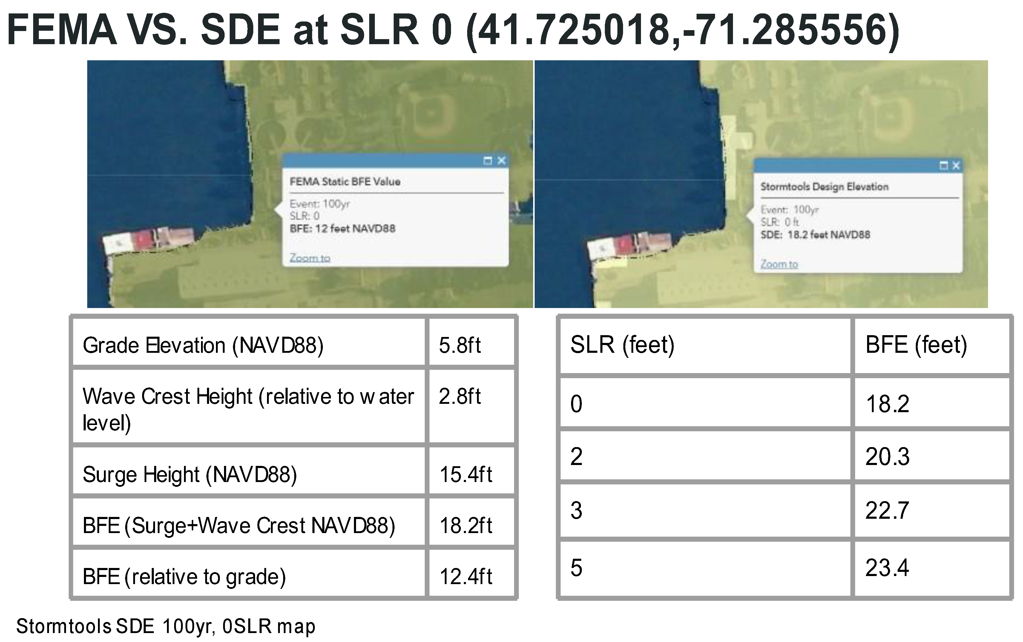
Figure 4 shows the BFE level for the 100 yr storm with SLR based on the SDE maps, with SLR values increasing from 0 to 5 ft. The breakdown by surge and wave crest are provided relative to grade and NAVD88 (left panel). The location of the data is provided in the upper panel. The BFE for this location from FEMA FIRM is 12 ft and from the SDE maps 18.2 ft (no SLR). The difference between the two estimates is consistent with the fact that FEMA uses the mean value for the storm surge height, while the SDE maps use the upper 95% confidence limit, as a hedge against uncertainty in the data and analysis. More details on this are provided in [
8]. The regulatory standards for SLR for the study area are established by the RI Coastal Resources Management Council (RI CRMC) with estimates based on NOAA High Levels in 2017 for Newport, RI. SLR values of 3 ft approximately correspond to projections for 2050 and 5 ft for 2070. It is noted that the present analysis is consistent with a study performed on behalf of the RI Department of Environmental Management (RI DEM) looking at the impact of flooding with climate change (SLR) on all the WWTF in RI [
9]. It is noted that there is limited spatial variability in BFEs over the footprint of the WWTF for both FEMA and SDE maps. Given its proximity to the coast the grade elevation is approximately 6 ft (NAVD88).
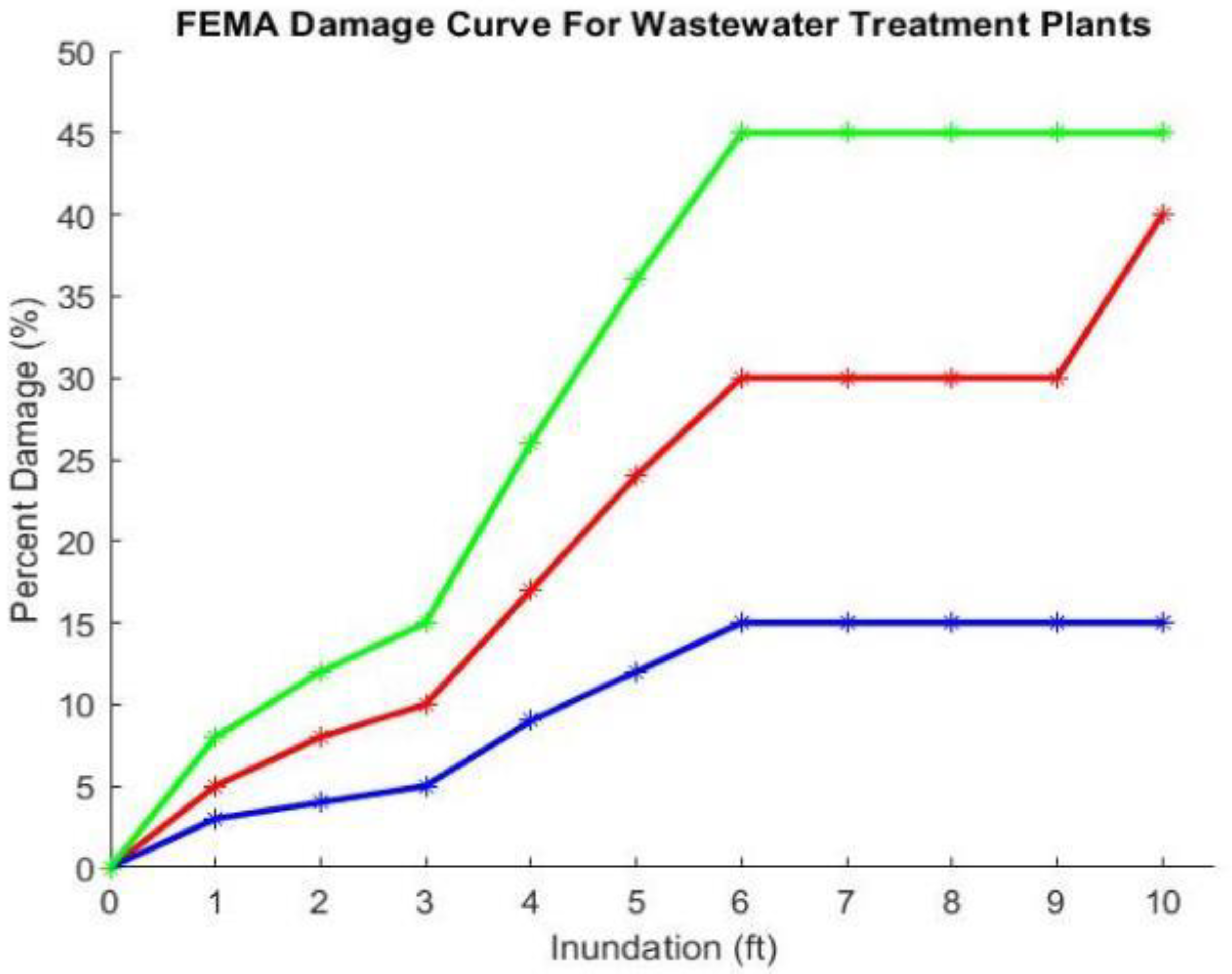
The FEMA HAZUS WWTF damage curves are shown in
Figure 5 [
6,
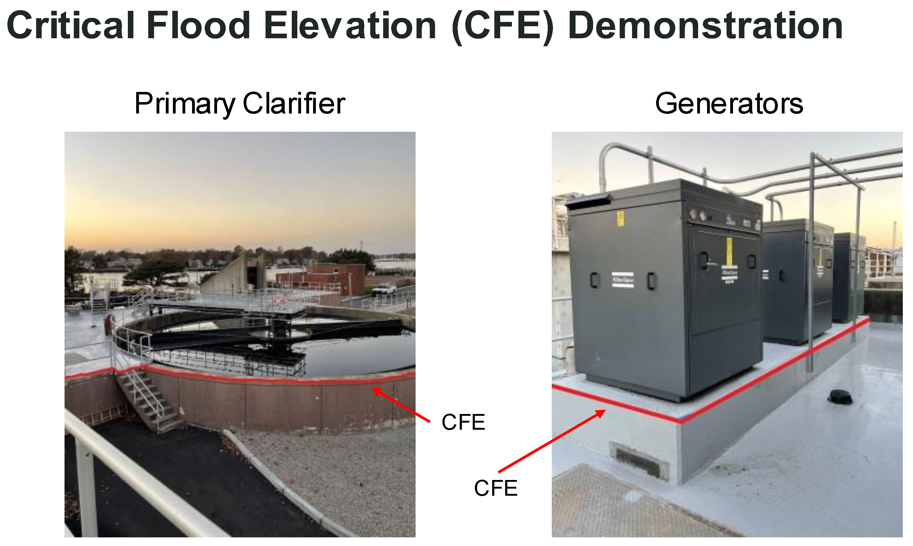
7]. Values are provided for average, more than average, and less than average vs. inundation levels. The reference levels for inundation are not specified, but it is assumed that this represents elevation relative to when the facility becomes inundated. Only one curve is provided for the entire facility, so it assumed that the curve represents the average for all components of the facility. With this assumption the present analysis determined the critical flood elevation (CFE) for each component of the facility and then estimated the level of inundation for each component above the CFE. The CFE represents the elevation above which flood waters cause damage to the facility.
Figure 6 shows an example of the CFE for the primary clarifier and emergency generators for the Warren WWTF.
Table 1 shows the grade elevation, CFE, FEMA BFE, and SDE BFEs (0, 2, 3, and 5 ft SLR) for each component of the Warren WWTF. Color coding for the individual components of the system is consistent with
Figure 3. The CFE values were determined by Woodard and Curran [
10] as part of their study and their overview of the upgrade of the facility on behalf of the Town of Warren, RI to make the system more climate resilient.
Estimated damages for individual components of the Warren, RI WWTF, as function of SLR, are provided in
Table 2. Average damages are provided first, followed by lower and upper bounds in parenthesis, below. Values are given for FEMA BFE and SDE BFE, with increasing SLR (0 to 5 ft). It is noted that the percent damages in
Table 2 are blocked by the selected inundation level. As an example, if the inundation is in the range of 3.01 to 3.99 ft, then damage is the same at 17% for the most likely value. The damages increase with SLR, with the primary settling tanks, head works, and chlorination tanks showing the highest damage and the aeration and reactor tanks the least. FEMA based estimates are much lower (<3%) than those using the SDE maps because the BFE is so much lower (FEMA BFE—12 ft vs. SDE—18 to 24 ft).
The average damage vs. BFE for FEMA FIRMs and SDE with SLR, averaged over all components of the facility with equal weighting by component, are provided in
Table 3. The value losses, assuming a plant value of
$50 M, are also provided and increase from about
$1/2 M to
$14 M, with increasing sea level rise from 0 to 5 ft. The plant value is based on input from the facility manager and an external review by an independent wastewater treatment expert (personal communication, Doug Hankins, PE, Wright Pierce, 18 November 2021). Average damage is very limited (less than 1%), if FEMA FIRM BFEs are used (first column), with their low BFE, but increases rapidly when SDE values are used, increasing from 16 to 28% as SLR increases from 0 to 5 ft.
4. Validation of HAZUS WWTF Damage Curves by Application to March/April 2010 Flooding Event in Pawtuxet River, RI
A review of FEMA HAZUS damage curves for WWTF facilities [
6,
7] reveal several areas of concern.
- (1)
The damage curves are for the facility as a whole and do not consider damage to individual components of the facility. In many cases damage to facilities maybe partial with selected components of the plant impacted and others experiencing no impacts at all. It is not clear how damages are to be estimated if only select components are inundated.
- (2)
The metric for specifying flooding is the level of inundation for the entire facility. The use of a metric such as critical flood elevation (CFE) to determine whether flooding has occurred is not mentioned but it is presumed to be part of the consideration for selecting the inundation level.
- (3)
The damage curves are independent of the size (design flow rate) of the facility.
- (4)
There is no data or references in the FEMA HAZUS Flood manual [
5,
6] that would allow a user to evaluate the supporting information for the damage curves. When contacted the FEMA HAZUS Help Desk was unable to find any information in support of the damage curves (personal communication, Doug Bausch, HAZUS Help Desk, 12 January 2022).
Given this situation, it appeared prudent to determine whether one could find any applications that validated the WWTF damage curves. A literature review was unable to find any case examples where validation was demonstrated. Typical papers [
11] showed application of the damage curves to select WWTF and storm events (e.g., hurricane Sandy 2012, coastal New York City) but no validation.
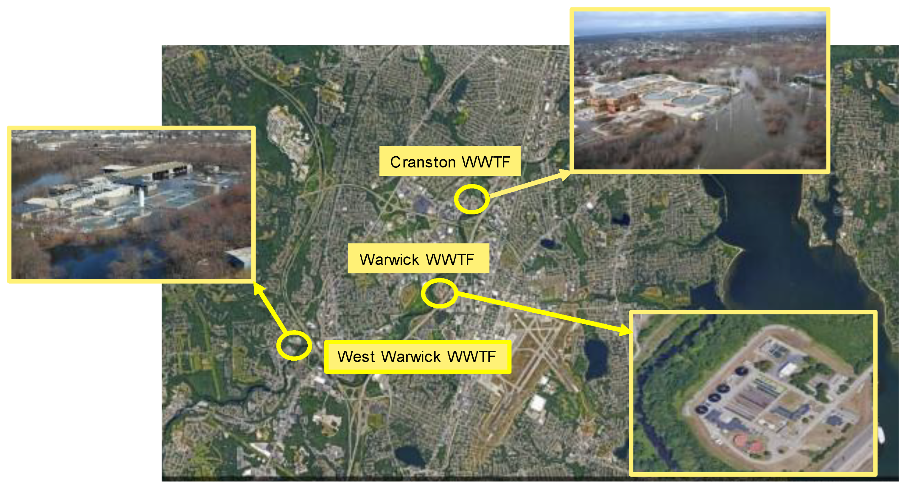
To that end, the authors undertook an effort to validate the damage curves by applying the method to Cranston, Warwick, and West Warwick WWTF located on Pawtuxet River, RI (
Figure 7) that were subject to damage from a 500 yr flooding (compound, three separate rain events) that occurred over a several day period in March/April 2010 [
12]. The inundation levels for the event have been documented by an analysis performed by the US Geological Survey (USGS) based on gauge station observations [
13,
14]. A detailed hindcast of the event has also been performed and validated with these observations [
15]. The locations of the three facilities are well above the high tide line and were subject to rainfall and associated runoff induced flooding, but not storm surge.
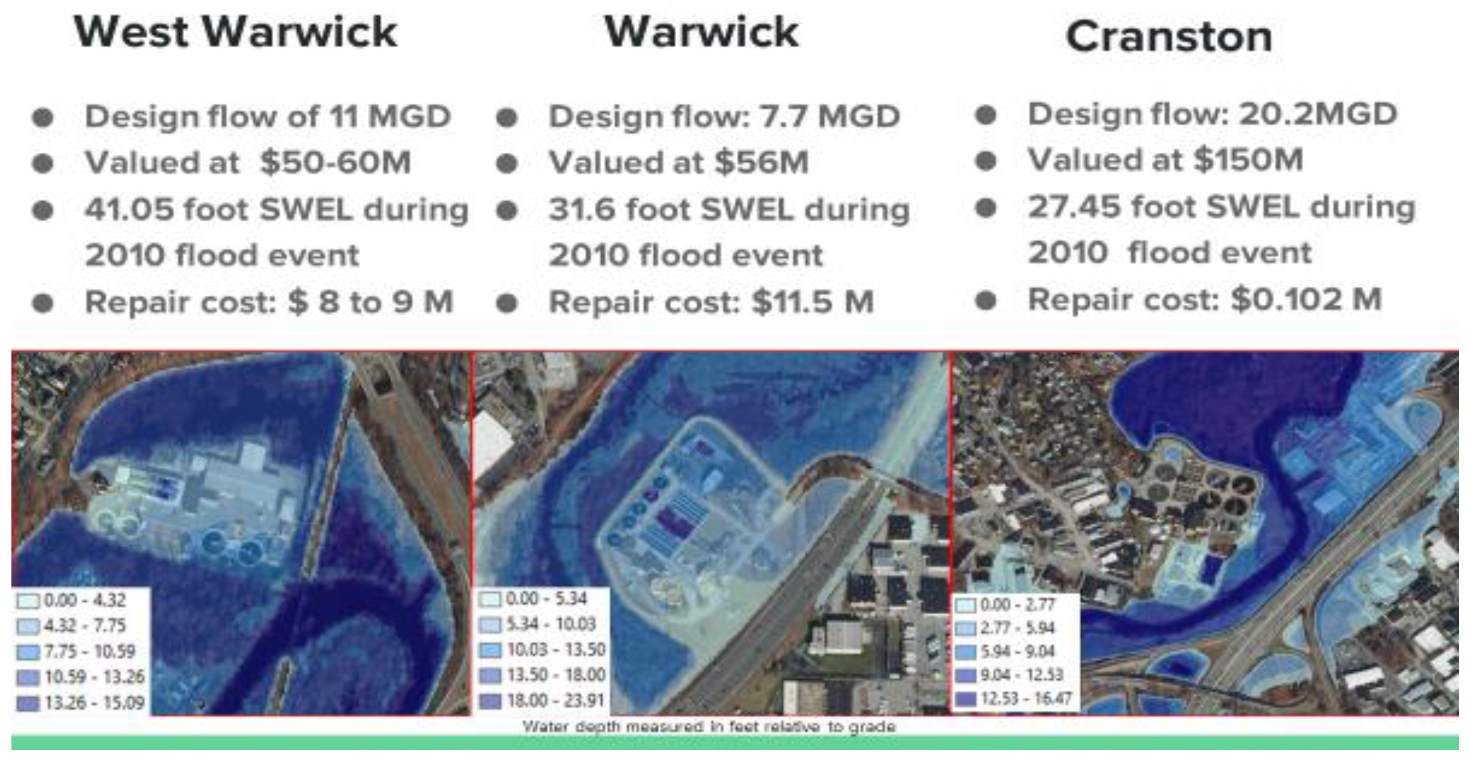
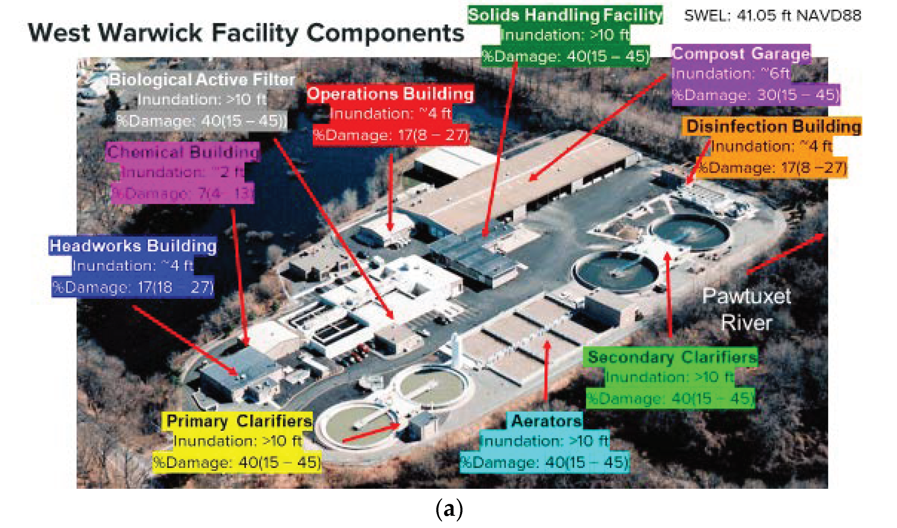
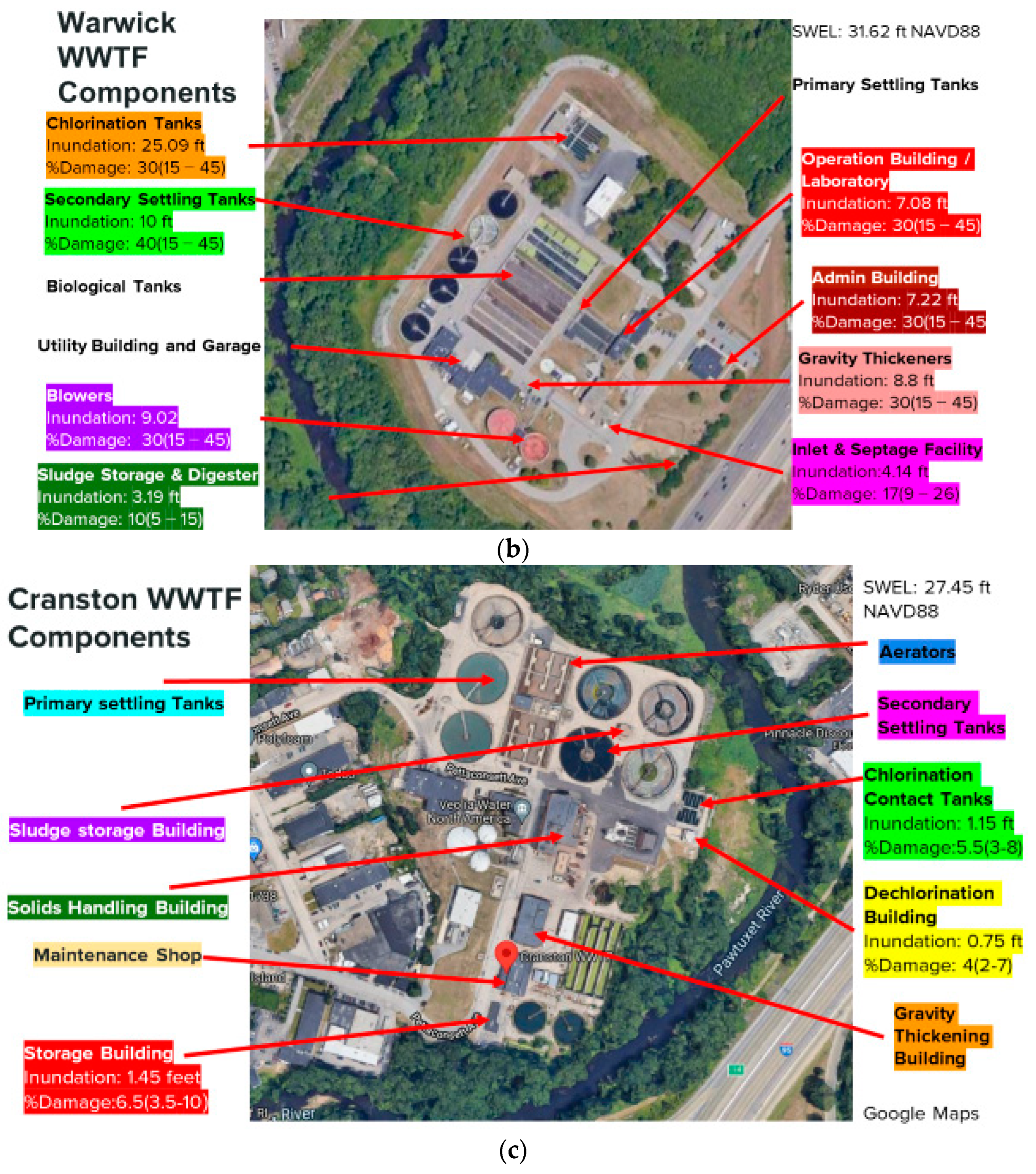
Figure 8 shows a contour map of the flooding for each facility at the peak SWEL (still water elevation) during the March/April 2010 flood event. Values are referenced to local grade elevation. The contour intervals (ft) are shown in the lower left corner of each map and vary between maps. It is noted that the SWEL is significantly higher for the West Warwick facility (41.05 ft) compared to that for the Warwick and Cranston facilities (31.6 ft and 27.45 ft, respectively). The difference is explained by the presence of a dam between the West Warwick and Warwick and Cranston facilities with a grade elevation change of approximately 6 ft. The maps clearly show that the West Warwick and Warwick facilities experienced significant flooding across the entire facility, while flooding for the Cranston facility was quite limited. The design flow rates for the West Warwick and Warwick facility are also provided and are comparable (11 MGD and 7.5 MGD), while those for the Cranston facility are about twice as large (20.2 MGD). Finally, the value of the facility and estimated costs to repair the facility were provided by the plant operators. The cost to repair the facility are consistent with the figures that show peak flooding, highest for West Warwick and Warwick and lowest for Cranston.
The damages to each component of the WWTF were estimated using the FEMA HAZUS damage curves. The elevations and CFEs for each component of the facilities were either provided by the plant operator or by measurement using Real Time Kinematic (RTK) mapping techniques [
5].
Figure 9 shows an image of the components for each facility, West Warwick (
a), Warwick (
b), and Cranston (
c). For each component, the level of inundation relative to the CFE is provided and the damage estimates showing the average, followed by below and above average damage (average (lower–upper)) are provided. Note that if the component was not impacted, no values for damage are provided. A review of the three figures clearly show that damage is predicted for most of the components of the West Warwick and Warwick facilities, with very limited damage for the Cranston facility. This is consistent with the flooding maps shown in
Figure 8.
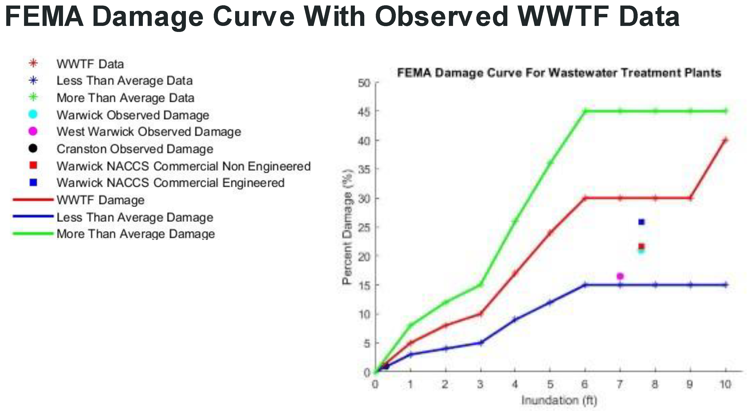
The value, value loss, observed percent damage and FEMA HAZUS based estimates of damage for West Warwick, Warwick, and Cranston WWTF are provided in
Table 4. FEMA HAZUS damages for average (less than and more than average) are also given. The observed damages for West Warwick and Warwick facilities are approximately the same (18 and 21%), while those for the Cranston facility are much lower (<1%). This is consistent with the flooding maps shown in
Figure 8. The FEMA HAZUS damage values are also comparable for the West Warwick and Warwick facilities (28.8% vs. 29.7%) and <1% for the Cranston facility.
Figure 10 shows the same data as
Table 4, but in this case as a graphic. The percent damage vs. inundation curves from FEMA HAZUS, including less than(blue), average(red) and more than average(green) values are provided. Estimates of observed damage for the Warwick, West Warwick, and Cranston WWTF based on data from the 2010 flooding event. The figure shows that the observed damages are slightly higher than the lower bound FEMA HAZUS estimate and lower than the average value. Estimates of damage for the Cranston facility are very low (<1%) consistent with the limited spatial extent of flooding of this facility (
Figure 8).
Damages to the Warwick facility were also made using NACCS damage curves for commercial engineered and non-engineered structures that are integrated into CERI [
1,
16]. The conceptual framework of this strategy is that the components of the WWTF are in many cases like those in either commercial engineered or non-engineered structures. This assumes that most of the major components of the facility are engineered/non engineered structures (e.g., tanks, structures of varying dimensions, etc.). The effort was undertaken to see how this approach might be used to estimate damages. Details on its application to the Warwick, WWTF are provided in [
5]. The Warwick facility was selected for this analysis given that it had the most detailed measurements of the elevation of all key components of the WWTF. The results of the analysis are shown in
Figure 10 (red and blue squares) and give damage percentages slightly lower than using the average FEMA HAZUS damage curve but higher than the less than average value. The commercial engineered damage is slightly higher than the non-engineered commercial damage, which is comparable to the observed value.
5. Discussion of Results
Application of CERI using HAZUS damage curves for the Warren, RI wastewater treatment plant show the damage for 100 yr flood events using FEMA FIRM BFE estimates and those from STORMTOOOLS SDEs with increasing values of SLR. When the FEMA FIRMS are employed to estimate the BFE, the damage is very limited (several percent) and only occurs for the primary settling tanks and the headworks. This is a result of fact that most of the components of the facility have CFEs that are higher than the FIRM BFEs. The damages are projected to increase when SDE maps are used since they have higher BFE than FEMA FIRM, since they use the upper 95% confidence level for flood inundation levels. SDE maps also explicitly consider SLR which increases the BFE and thus the projected damage. The increase in damage scales directly with the increase in SLR.
In evaluating the resilience to coastal flooding of the Warren WWTF the contractor [
10] noted that if some of the components of the facility experienced short term flooding but repairs were straightforward, and costs were low, then the cost to raise that component of the facility was not warranted. This strategy may be applicable to higher levels of inundation but will require a detailed engineering and cost analysis. It is noted that the grade elevation of the entire facility is approximately 6 ft (NAVD88). As sea level rises, the facility becomes increasingly at risk to more frequent flooding (shorter return period storms). As an example, a 50 yr storm currently has a BFE of 14.7 ft, with 3 ft of SLR, this value, 17.7 ft is consistent with current 100 yr conditions. In this case, a protective berm or retaining wall around the facility might be the most cost-effective operation.
The April/May 2010 Pawtuxet River flood event and its impact on the Cranston, Warwick, and West Warwick WWTF represented a very rare opportunity to validate the FEMA HAZUS damage curves. Estimates of the flood levels of the river were extremely well documented by the facility operators and from USGS gauging stations on the river. Damages to the facility, while time consuming and difficult to obtain, were documented by the facility operators and evidenced by contracts or insurance claims to perform the repairs. One confounding issue was to separate out costs to upgrade the facilities when repairs were being performed (e.g., rising a berm around a facility). The validation exercise showed the observed damages were below FEMA HAZUS’s most likely damage and above the lower bound.
The analysis provided no insight into the size of the facility on damage. The Warwick and West Warwick facilities are comparable in their design capacity and experienced comparable damages. The Cranston facility has twice the design capacity of the other two, but very limited damage, because of very low inundation levels. It has been particularly frustrating not to be able to find the underlying technical literature that supports the damage curves as provided in the FEMA HAZUS user’s manual or to find published work that has attempted to validate the model [
6,
7,
17].
To provide a more robust analysis of damage it might be useful to look at the WWTF as a series of independent but closely link components. Damages from flooding for each component could be assessed and then damages determined across the entire facility. This would allow details on each component to be evaluated including their grade elevation, design characteristic (e.g., CFE), flooding levels, flood proofing, exposure to waves, and others. The application of the damage curves in CERI for engineered and non-engineered structures in the present study, suggests that this strategy might be appropriate in moving forward.
6. Conclusions
Application of CERI, using the FEMA HAZUS damage curves, predicted the impact of flooding with SLR for the Warren, RI WWTF. The SDE based BFEs increased from 18 to 24 ft due with SLR (0 to 5 ft) and the resulting average damage across all components of the facility also increased with SLR from 16% (SLR—0 ft), 22% (SLR—2 ft), 26% (SLR—3ft), to 28% (SLR—5 ft). If the FEMA FIRM BFE (12 ft) is employed little damage (<1%) is predicted. There is no change in the FEMA based estimate with SLR since FEMA BFEs do not consider the impacts of SLR. The difference between the FEMA FIRM results and those using SDE estimates is that FEMA assumes mean values for flood inundation levels for the 100 yr event, while SDE maps uses the upper 95% value, as hedge against uncertainties in the data and analysis methods. It is noted that modifications to the facility that systematically raise the CFE for key components will reduce the flooding impact. In deciding whether to raise these components a cost analysis would be prudent to study the cost of flood proofing/raising the component vs. the cost to repair the component post a flood event.
The March/April 2010 flood (500 yr) event in the Pawtuxet River, RI basin and its impact on the West Warwick, Warwick, and Cranston WWTF represented a rare opportunity to validate FEMA HAZUS damage curves for an actual event. The characteristics of this rainfall induced flooding event (SWEL) were well documented by an analysis of data from USGS gauging station data, a hindcast of the event using state of the art hydrologic models, and observations by plant operators. The plant personnel were able to provide details on the various components of the WWTF (grade elevations and CFE) and the damages and costs to repair the facility. Given this information the authors were able to estimate the percent damage by dividing the repair cost by the plant value. The analysis showed that the West Warwick and Warwick treatment plant incurred comparable damage at 18 and 21%, respectively. The damage to the Cranston facility was very low (<1%). The substantial difference between the damage to facilities was due to the degree of flooding, with West Warwick and Warwick facilities being completely inundated and the Cranston facility only having a few components impacted. Application using the FEMA HAZUS WWTF damage curves showed average damages of 28.8–29.7% for the West Warwick and Warwick facilities, respectively and less than <1% for the Cranston facility. Upper and lower bounds for the West Warwick and Warwick WWTF were in the range of 12 to 40%, and below <1% for Cranston. The average FEMA HAZUS damages (approximately 30%) are higher than observed values (18 to 21%) but larger than the below average values (11.8–13.4%). This analysis suggests that the FEMA HAZUS predictions are consistent with observations but slightly on the high side. Application of the NACCS damage curves, assuming that the components of the treatment plant can be represented as engineered and non-engineered structures shows comparable results to the observations. The current effort shows the importance of validating the WWTF damage curves to improve the support for their use in making accurate flood damage estimates.
This study has highlighted the importance of validating model predictions by applying the approach to assess the damage to WWTF from actual flooding events. It also suggests that a component-by-component assessment is likely warranted to provide insight into how best to mitigate damage in the redesign of the facilities.
Author Contributions
Conceptualization: M.L.S.; methodology and software: T.D., P.K. and L.S. writing original draft: M.L.S.; writing—review and editing: all authors; visualization: T.D., P.K. and L.S.; supervision and administration: M.L.S., C.B. and C.S. All authors have read and agreed to the published version of the manuscript.
Funding
This project was completed as part of a senior capstone design project in Ocean Engineering at the University of RI, Narragansett, RI and received no external funding. A graduate student in Ocean Engineering, Sandra Deeb, was supported by the URI Sea Grant program to assist the students.
Institutional Review Board Statement
Not applicable.
Informed Consent Statement
Not applicable.
Data Availability Statement
Not applicable.
Acknowledgments
The following individuals provided support to the students in the completion of their study on estimating damage to WWTF from coastal flooding. David Komiega, Wastewater Facility Manager–Warren, RI; Jim Geremia, James J. Geremia & Associates, Inc., West Warwick, RI; Earl Salisbury, Project Manager, Veolia North America–Cranston, RI; and Betty Anne Rodgers, Executive Director, Warwick Sewer Authority, Warwick, RI. William Patenaude and Alex Pinto, RI Department of Environmental Management (RI DEM) provided links to key individuals involved in responding to the 2010 flood event at the WWTF.
Conflicts of Interest
The authors declare no conflict of interest.
Abbreviations
| ACOE | Army Corp of Engineers |
| BFE | Base Flood Elevation |
| CERI | Coastal Environmental Risk Index |
| CFE | Critical Flood Elevation |
| FEMA | Federal Emergency Management Agency |
| FIRM | FEMA FIRM- Flood Insurance Rate Maps |
| GIS | Geographic Information System |
| HAZUS-MH | FEMA nationally standardized risk modeling methodology, Multi Hazard (MH). |
| MGD | Million Gallons per Day |
| NACCS | North Atlantic Coast Comprehensive Study, USACE |
| NAVD88 | National American Vertical Datum, 1988 |
| OCE | Ocean Engineering, URI |
| PE | Professional Engineer |
| RI | Rhode Island |
| RI CRMC | RI Coastal Resources Management Council |
| RI DEM | RI Department of Environmental Management |
| RTK | Real Time Kinematic |
| SDE | STORMTOOLS Design Elevation maps |
| SLR | Sea Level Rise |
| STORMTOOLS | Tools to support flood risk assessment |
| SWEL | Still Water Elevation |
| URI | University of RI |
| USD | US dollars |
| USACE | US Army Corp of Engineers |
| USGS | US Geological Survey |
| WWTF | Wastewater Treatment Facility |
References
- Spaulding, M.L.; Grilli, A.; Damon, C.; Crean, T.; Fugate, G.; Oakley, B.A.; Stempel, P. STORMTOOLS: Coastal Environmental Risk Index (CERI). J. Mar. Sci. Eng. 2016, 4, 54. [Google Scholar] [CrossRef] [Green Version]
- Spaulding, M.L.; Grilli, A.; Damon, C.; Hashemi, R.; Kouhi, S.; Fugate, G. STORMTOOLS Design Elevation (SDE) Maps: Including Impact of Sea Level Rise. J. Mar. Sci. Eng. 2020, 8, 292. [Google Scholar] [CrossRef] [Green Version]
- Spaulding, M.L.; Grilli, A.; Damon, C.; Crean, T.; Fugate, G. Application of STORMTOOLS Coastal Environmental Risk Index (CERI) to Inform State and Local Planning and Decision Making along the Southern RI Shoreline. J. Mar. Sci. Eng. 2020, 8, 295. [Google Scholar] [CrossRef]
- Spaulding, M.L.; Grilli, A.; Damon, C.; McKenna, B.; Christensen, M.; Vinhateiro, N.; Boyd, J.; Fugate, G. STORMTOOLS, Coastal Environmental Risk Index (CERI) Risk and Damage Assessment. App. J. Mar. Sci. Eng. 2020, 8, 129. [Google Scholar] [CrossRef] [Green Version]
- Artis, R.; Carr, K.; Donahue, T.; Fagan, J.; Krekorian, P.; Lange, E.; Morris, O.; Silvia, B.; Schwarzer, M.; Swift, L. Impact of Coastal Flooding on Commercial Structures and Infrastructure on the Warren, RI Waterfront; Report Prepared for University of Rhode Island Senior Design Capstone Course, Ocean Engineering: Narragansett, RI, USA, 2022. [Google Scholar]
- FEMA. HAZUS-MH Flood Model; Technical Manual; FEMA: Washington, DC, USA, 2009. [Google Scholar]
- Scawthorn, C.; Flores, P.; Blais, N.; Seligson, H. HAZUS-MH flood loss estimation methodology. II. Damage and loss assessment. Nat. Hazards Rev. 2006, 7, 72–81. [Google Scholar] [CrossRef]
- Spaulding, M.; Grilli, A.; Damon, C.; Fugate, G.; Isaji, T.; Schambach, L. Application of state of art modeling techniques to predict flooding and waves for coastal area with a protected bay. J. Mar. Sci. Eng. 2017, 5, 10. [Google Scholar] [CrossRef] [Green Version]
- Woodard-Curran and RPS Group. Implications of Climate Change for RI Wastewater Collection and Treatment Infrastructure; RI Department of Environmental Management: Providence, RI, USA, March 2017. [Google Scholar]
- Memo from Jon Himlan, Woodard and Curran, Providence, RI to Jan Rietsma, Town Manager, Warren, RI entitled Warren WWTF Improvements Project Flood Resiliency Evaluation. 2017.
- Sun, Q.; Nazari, R.; Karimi, M.; Rabbani Fahad, M.G.; Peters, R.W. Comprehensive Flood Risk Assessment for Wastewater Treatment Plants under Extreme Storm Events: A Case Study for New York City, United States. Appl. Sci. 2021, 11, 6694. [Google Scholar] [CrossRef]
- Holbrook, N.Q. The Flood Crews 2010, a History of the Rhode Island’s 2010 Floods as Told by the State’s Wastewater Collection and Treatment Operators; RI Department of Environmental Management (RI DEM): Providence, RI, USA, 2017. [Google Scholar]
- Bent, G.C.; Lombard, P.J. Flood-Inundation Maps for the Pawtuxet River in West Warwick, Warwick, and Cranston, Rhode Island; Scientific Investigations Report; US Geological Survey: Reston, VA, USA, 2018. [CrossRef]
- Zarriello, P.J.; Ahearn, E.A.; Levin, S.B. Magnitude of Flood Flows for Selected Annual Exceedance Probabilities in Rhode Island through 2010 (ver. 1.2, revised March 2013); U.S. Geological Survey Scientific Investigations Report 2012-5109; US Geological Survey: Reston, VA, USA, 2012; 81p.
- Kouhi, S.; Hashemi, R.; Kian, R.; Spaulding, M.; Lewis, M.; Ginis, I. Flood risk in past and future: A case study for the Pawtuxet River’s record-breaking March 2010 flood event. J. Flood Risk Manag. 2020, 13, e12655. [Google Scholar] [CrossRef]
- US ACE. North Atlantic Coast Comprehensive Study (NACCS). Resilient Adaptation to Increasing Risk, Physical Depth Damage Function, Summary Report. 2015. Available online: http://www.nad.usace.army.mil/Portals/40/docs/NACCS/10A_PhysicalDepthDmgFxSummary_26Jan2015.pdf (accessed on 1 September 2022).
- Scawthorn, C.; Blais, N.; Seligson, H.; Tate, E.; Mifflin, E.; Thomas, W.; Murphy, J.; Jones, C. HAZUS-MH Flood Loss Estimation Methodology. I: Overview and Flood Hazard Characterization. Nat. Hazards Rev. 2006, 7, 60–71. [Google Scholar] [CrossRef]
Figure 1.
STORMTOOLS Coastal Environmental Risk Index (CERI) flow chart [
1].
Figure 1.
STORMTOOLS Coastal Environmental Risk Index (CERI) flow chart [
1].
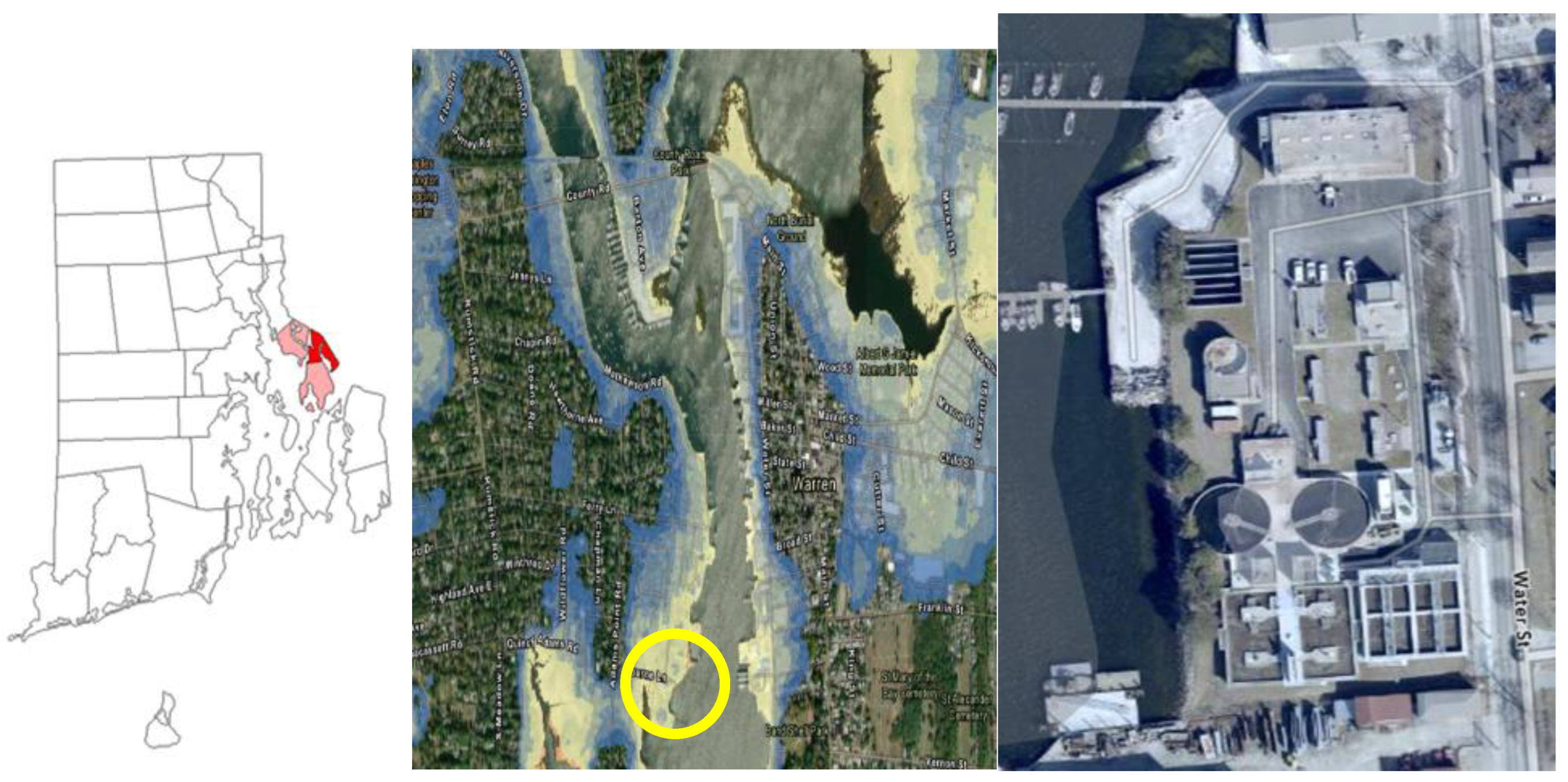
Figure 2.
Location of Warren WWTF on the Warren River, RI. Location of Warren, RI in Narragansett Bay (left panel, dark red is the Town of Warren and light red the Town of Barrington, to the north, and Town of Bristol, to the south), image of coastal flooding (100 yr) 4 to 16 ft above grade (blue to light yellow) (center panel) and close-up of the Warren WWTF (right panel, see yellow circle in center panel for location) of the WWTF. (The width of the right panel is 550 ft, and the height of 750 ft). The WWTF is located at 41 43′33” N and 71 17′02” W.
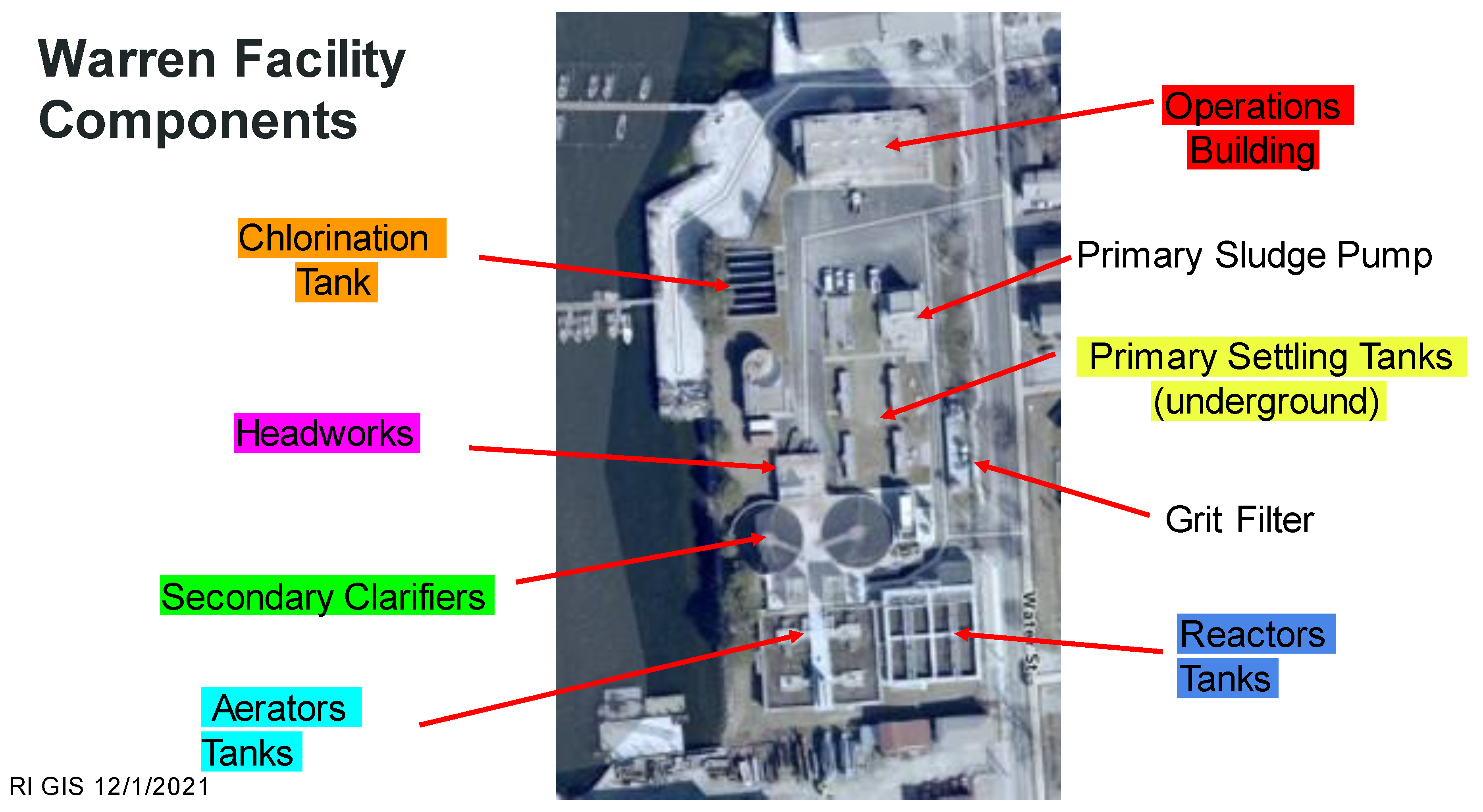
Figure 3.
Major components of the Warren, RI WWTF. These are color coded to help in presenting the results of the analysis. Grit filter and primary sludge pump are not color coded since they experience only limited damage for short term flooding.
Figure 3.
Major components of the Warren, RI WWTF. These are color coded to help in presenting the results of the analysis. Grit filter and primary sludge pump are not color coded since they experience only limited damage for short term flooding.
Figure 4.
Grade elevation, 100 yr surge height, wave crest height, BFE relative to NAVD88 and grade (lower-level left panel) and impact of SLR on BFE from SDE maps with sea level rise (lower, right panel) for 100 yr flooding. The upper-level left panel shows FEMA BFE, relative to NAVD88, and upper right panel shows BFE, relative to NAVD88, based on SDE maps for the facility for no SLR.
Figure 5.
FEMA HAZUS flood damage curves for WWTF. Values are provided for the average (red) and less than average (blue) and more than average (green) vs. inundation levels [
6,
7]. The values given by * are taken directly from the FEMA HAZUS damage table for WWTF.
Figure 5.
FEMA HAZUS flood damage curves for WWTF. Values are provided for the average (red) and less than average (blue) and more than average (green) vs. inundation levels [
6,
7]. The values given by * are taken directly from the FEMA HAZUS damage table for WWTF.
Figure 6.
Example of vertical locations of Critical Flood Elevation (CFE) for primary clarifier and generators, Warren WWTF.
Figure 6.
Example of vertical locations of Critical Flood Elevation (CFE) for primary clarifier and generators, Warren WWTF.
Figure 7.
Locations of the West Warwick, Cranston, and Warwick WWTF on the Pawtuxet River, RI. Center map shows the location of the facilities relative to upper Narragansett Bay and the Providence River.
Figure 7.
Locations of the West Warwick, Cranston, and Warwick WWTF on the Pawtuxet River, RI. Center map shows the location of the facilities relative to upper Narragansett Bay and the Providence River.
Figure 8.
Map of peak flood elevation (SWEL-Still Water Elevation, in ft relative to grade elevation) of the West Warwick, Warwick, and Cranston WWTF for the March/April 2010 flood event. The upper panel shows the design flow rates, value of the facility, still water flood elevation, and estimated repair costs provided by the plant operators.
Figure 9.
Aerial photographs showing the inundation and damage to each component of the West Warwick (a), Warwick (b), and Cranston (c) WWTF. Inundation values are measured relative to CFEs for each component of the facility and damages for average (below and above average) are provided.
Figure 9.
Aerial photographs showing the inundation and damage to each component of the West Warwick (a), Warwick (b), and Cranston (c) WWTF. Inundation values are measured relative to CFEs for each component of the facility and damages for average (below and above average) are provided.
Figure 10.
Percent damage vs. inundation curves from FEMA HAZUS, including less than average(blue), average(red), and more than average(green) values. Estimates of observed damage for the Warwick, West Warwick, and Cranston WWTF are also shown. Damages to the Warwick facility are also shown using NACCS damage curves [
16] for commercial engineered and non-engineered structures.
Table 1.
Grade elevation, CFE, FEMA BFE, and STORMTOOLS BFE (0, 2, 3, and 5 ft SLR) for each component of the Warren, RI WWTF. Color coding for components is consistent with
Figure 3.
Table 1.
Grade elevation, CFE, FEMA BFE, and STORMTOOLS BFE (0, 2, 3, and 5 ft SLR) for each component of the Warren, RI WWTF. Color coding for components is consistent with
Figure 3.
| FEMA Base Flood Elevation Compared to STORMTOOLS |
|---|
| Source | STORMTOOLS | Woodard& Curran Report | STORMTOOLS | STORMTOOLS | STORMTOOLS | STORMTOOLS | STORMTOOLS |
| Structure | Grade Elevation | CFE | FEMA BFE | 100yr 0 SLR BFE | 100yr 2 SLR BFE | 100yr 3 SLR BFE | 100yr 5 SLR BFE |
| | (NAVD 88) (feet) | (NAVD 88) (feet) | (NAVD 88) (feet) | (NAVD 88) (feet) | (NAVD 88) (feet) | (NAVD 88) (feet) | (NAVD 88) (feet) |
| Primary Settling Tanks | 5.6 | 11.53 | 12 | 17.7 | 19.92 | 20.93 | 22.98 |
| Headworks | 6.4 | 11.7 | 12 | 18 | 20.2 | 21.2 | 23.25 |
| Chlorination Tank | 9.1 | 12.7 | 12 | 19 | 21.02 | 22.03 | 24.09 |
| Second Clarifiers | 5.9 | 14.53 | 12 | 18.2 | 20.2 | 21.2 | 23.25 |
| Operations Building | 10.9 | 15.2 | 12 | 18.3 | 20.57 | 21.55 | 23.56 |
| Aeration Tanks | 2.1 | 17.7 | 12 | 16.3 | 18.33 | 19.35 | 21.43 |
| Reactor Tanks | 9.4 | 22 | 12 | 18.4 | 20.5 | 21.5 | 23.6 |
Table 2.
Estimated damages (%) for individual components of the Warren, RI WWTF. Average damages are provided first, followed below by lower and upper bounds in parenthesis. Values are provided for FEMA BFE and SDE BFE with increasing SLR (0 to 5 ft).
Table 2.
Estimated damages (%) for individual components of the Warren, RI WWTF. Average damages are provided first, followed below by lower and upper bounds in parenthesis. Values are provided for FEMA BFE and SDE BFE with increasing SLR (0 to 5 ft).
| FEMA HAZUS 100 yr Percent Damage with SLR |
|---|
| Structure | CFE (NAVD 88) (feet) | FEMA BFE Percent Damage | 100-yr 0 SLR Percent Damage | 100-yr 2 SLR Percent Damage | 100-yr 3 SLR Percent Damage | 100-yr 5 SLR Percent Damage |
| Primary Settling Tanks | 11.53 | 3 | 30 | 30 | 40 | 40 |
| (1–5) | (15–45) | (15–45) | (15–45) | (15–45) |
| Headworks | 11.7 | 2 | 30 | 30 | 40 | 40 |
| (1–3) | (15–45) | (15–45) | (15–45) | (15–45) |
| Chlorination Tank | 12.7 | 0 | 30 | 30 | 40 | 40 |
| (15–45) | (15–45) | (15–45) | (15–45) |
| Second Clarifiers | 14.53 | 0 | 17 | 30 | 30 | 30 |
| (9–26) | (15–45) | (15–45) | (15–45) |
| Operations Building | 15.2 | 0 | 17 | 30 | 30 | 30 |
| (9–26) | (15–45) | (15–45) | (15–45) |
| Aeration Tanks | 17.7 | 0 | 0 | 5 | 8 | 17 |
| (3–8) | (4–12) | (9–26) |
| Reactor Tanks | 22 | 0 | 0 | 0 | 0 | 5 |
| (3–8) |
| | FEMA HAZUS | | Average | | |
| | Percent Damage | (less than average- more than average) |
Table 3.
Estimated average damage (%) and loss value ($ Million) vs. BFE (FEMA, SDE with SLR).
Table 3.
Estimated average damage (%) and loss value ($ Million) vs. BFE (FEMA, SDE with SLR).
| Valuation of the Facility: $50M | | | |
|---|
| Design Flow: 5–6 MGD | | | |
|---|
| | 100 year storm | 100 year storm | 100 year storm | 100 year storm | 100 year storm |
| | 0SLR (FEMA) | 0 ft SLR | 2 ft SLR | 3 ft SLR | 5 ft SLR |
| Avg Damage (%) | 0.7 | 16 | 23 | 26 | 28 |
| | (0.2–1.1) | (9–27) | (13–33) | (13–34) | (15–37) |
| Value Loss | $0.40 | $8.00 | $11.50 | $13.00 | $14.00 |
| (million USD) | (0.1–0.6) | (4.5–13.4) | (6.5–16.5) | (6.5–17) | (7.5–18.5) |
| | FEMA HAZUS percent damage and value loss | | average | | |
| | | | (less than average- more than average) |
Table 4.
Value, value loss, observed percent damage, and FEMA HAZUS based estimates of percent damage for West Warwick, Warwick, and Cranston WWTF. FEMA HAZUS average (less than and more than average) are provided.
Table 4.
Value, value loss, observed percent damage, and FEMA HAZUS based estimates of percent damage for West Warwick, Warwick, and Cranston WWTF. FEMA HAZUS average (less than and more than average) are provided.
| Observed Damage vs. FEMA HAZUS Percent Damage |
|---|
| Facility | Value (USD) | Value Loss (USD) | Observed Percent Damage | FEMA HAZUS Percent Damage |
|---|
| West Warwick | ~$50–60 M | $8,875,475 | 15–18 | 28.8 |
| (11.8–36.4) |
| Warwick | ~$55 M | $11,499,496 | 21 | 29.7 |
| (13.4–40.1) |
| Cranston | ~$150 M | $102,544 | <1 | <1 |
| | FEMA Percent Damage | | Average | |
| | | | (Less than average-More than average) | |
| Publisher’s Note: MDPI stays neutral with regard to jurisdictional claims in published maps and institutional affiliations. |
© 2022 by the authors. Licensee MDPI, Basel, Switzerland. This article is an open access article distributed under the terms and conditions of the Creative Commons Attribution (CC BY) license (https://creativecommons.org/licenses/by/4.0/).

 ,
, 


