Article

New Wave Energy Converter Design Inspired by the Nenuphar Plant

Centre for Marine Technology and Ocean Engineering (CENTEC), Instituto Superior Tecnico, Universidade de Lisboa, 1049-001 Lisbon, Portugal
*
Author to whom correspondence should be addressed.
J. Mar. Sci. Eng. 2022, 10(11), 1612; https://doi.org/10.3390/jmse10111612
Submission received: 25 September 2022 / Revised: 17 October 2022 / Accepted: 27 October 2022 / Published: 1 November 2022
(This article belongs to the Special Issue Advances in Offshore Wind and Wave Energies)

Abstract

:
This paper presents the Nenuphar concept, an innovative wave energy converter designed to use the kinetic and the potential energy of sea waves, based on the motions of seven modules. First, the main characteristics of the Nenuphar and its work principle are presented. Afterwards, the mathematical formulation of its dynamics is introduced and its validation with a simplified device. A specific MATLAB code was developed to determine the dynamics of hinged, multi-directional bodies. Then, the system’s behaviour was analysed under different wave conditions. The system performance was not strongly dependent on the wave characteristics or the device inclination angle. This initial study confirms the Nenuphar as a potential technology to extract energy from waves.

1. Introduction

Wave energy is the renewable energy with the most abundant energy flux density [1]. The European Atlantic coastline is one of the more promising regions for wave energy extraction [2,3,4]. The wave power resource is estimated at 2.11 TW [5], although only a percentage of that massive amount is expected to be extractable [6,7]. The exploitation of ocean waves is of considerable significance to environmental protection, ocean defence and marine exploitation. Many countries and regions in the world are committed to ocean wave energy technology research and development (e.g., Portugal, UK, Australia) [8].
A considerable period of years has passed since the idea of a wave energy converter (WEC) originated. From the period that began at the final stage of the 18th century [9], many WECs have been proposed [10]. So far, there are more than 1000 WECs patented worldwide [11]. Even though today, this type of technology could be considered even at an early stage since a variety of converters exists, there is no particular relevance to any of them [12], and there is not yet a generalised commercial use for wave energy, mainly because of the high costs involved [13,14]. Wave power potential [15] and its potential to prevent climate change [16,17] make this industry a promising one. Among the wide variety of devices proposed, the attenuator (or hinged control device) combines a high-power capture efficiency with inherent survivability in extreme seas [18]. This system uses the movement principally around the axis hinge (Figure 1) to drive the electricity generation system, transforming the energy generated by waves into electrical power.
The attenuator can be considered as a promising WEC in terms of harnessing wave energy. After reviewing the project and research discussions [11,19,20,21], it was possible to conclude that these are generally large devices that require significant infrastructure. Moreover, the type of WECs developed are used only for one kind of energy conversion extraction (e.g., heave motion or pitch motion), not allowing for the exploitation of sea motion potential. In 1971, Sir Christopher Cockerell designed the first attenuator, the Cockerell Raft [22]. This device comprises a series of rafts hinged together, counted on top of each hinge with two hydraulic jacks and long pistons. The movement of the raft due to waves generates forces into the pistons, whose cylinders send pressurised fluid to the hydraulic motor. A few years later, Haren [23], conducted hydrodynamic studies using the following assumptions: shallow water, a raft width bigger than the wavelength and a linear power take-off (PTO) system. From these studies, he described that a system formed by two rafts would be better than other compositions because more rafts limit angular displacement, which reduces the energy conversion rate. With similar characteristics to the previous WEC, widely studied by Kraemer and McCormick [24], the McCabe Wave Pump must be considered. It comprises three floats linearly hinged and disposed of in parallel to the wave direction. The central float is attached to a submerged damper plate, which is designed to reduce motion. A hydraulic pump is also connected between the central float and the aft float, to make use of the rise and fall of the bodies. The hydraulic fluid could generate electricity or desalinize seawater with the help of a motor–generator [25]. The Pelamis, developed by Pelamis Wave Power Ltd., is an articulated structure composed of several cylindrical sections linked by hinged joints [18]. Incoming waves generate pitch and yaw motions in each segment joint. The joint motion is used to pump oil into high-pressure storage accumulators, which produce electricity in generators [26]. The SeaRay and StingRay are projects developed by Columbia Power Technologies [27]. The former consists of two oscillating bodies with a non-restricted pitch motion; they are connected to a central body whose inertia is enlarged by a submerged plate. The latter captures the energy from each passing wave and produces electricity onboard the device. The electricity generation process includes a series of steps that starts with transferring captured energy from the forward and aft floats for the two rotaries (low-speed, high-torque) electric generators onboard the WEC. DEXA is a raft-type WEC developed one decade ago by Ruol et al. [28]. The concept represents a floating breakwater wave transmission coefficient. The DEXA device was analysed on the shoreline using numerical simulation and physical experiment methods. Other studies have explored the effect of a farm of Pelamis converters on the coastline, using numerical simulation [29,30]. A similar concept was the subject of a study on the effect of wave farms as a sort of breakwater, protecting aquaculture installations [31]. Stansby et al. [32] recently introduced the M4 raft-type device. The machine is composed of three, cylindrical, vertically axisymmetric floats of different sizes. A steel arm rigidly connects the stern and mid floats. Wave energy is generated by the pitching motion between the bow and the rigid connection structure. The PTO for this system has been studied by Gaspar et al. [33]. Hydraulic-based PTOs have been used in many concepts that obtain wave energy from the relative dynamics of two bodies. A general concept was developed by Gaspar et al. in 2016 [34], further improved in 2017 and 2018 [35,36]. In the same way that some companies combine offshore wind with wave energy, in floating power plants [37], as explained by Marquis et al. [38], it is also possible to combine two different forms of wave energy conversion in the same device. This idea would increase the amount of electricity produced by the device, which in turn, could have a positive impact on the costs and feasibility of their installation.
In this study, the goal was to adapt an attenuator with a point absorber to the same device. The advantages of the union between two different wave conversion types resides in two main specifications: (i) both systems can be coupled, maintaining the performance characteristics for the production of energy that they each have separately and (ii) the combination would supposedly join two systems whose optimum operating ranges occur in different sea states, and through a leverage effect, would lead to a broader range of action, besides being mutually reinforcing. A similar concept was explored with the combination of this type of wave absorber with a wind energy device [39,40].
Generally, three central components represent a point absorber buoy: a heave plate, a flexible line and a power take-off system. The point absorber generates energy from the buoy motion. The power take-off system harnesses the forces generated by the interaction between the buoy and heave plate. Point absorbers have small dimensions compared with incident wavelength [41]. Energy is captured with the rise and fall of the waves. There are two main categories of point absorbers depending on whether the bottom end of the structure is fixed or if it is allowed to be in motion. Figure 1 shows a schema of a point absorber.
Several point absorbers have been developed. Below, those whose characteristics could be fused with an attenuator were mentioned. The Wavebob [42] is an axisymmetric point absorber whose heave motions are converted into energy. A high-pressure oil system is in charge of energy extraction. A buoy is rigidly connected to a heavy submerged body to increase the inertia and tuning to the average wave frequency. Under certain technical similarities with the previous WEC, Ocean Power Technologies developed the Power Buoy concept [43]. This model is composed of a reacting body fitted with a large-diameter heave plate. The heave plate increases the inertia through the added mass of the surrounding water [44]. The Uppsala Point Absorber was initially known as the Lysekil Project [45] and was developed by the company, Seabased AB [46]. This technology includes a directly driven, permanent magnet linear generator placed on the ocean floor. The buoy is linked to the generator using a connection line and a piston [47]. The L-10 was recently developed at Oregon State University in a joint venture with Columbia Power Technologies [27]. The L-10 [48] is a dual body system with a deep draft spar, around which a torus-shaped buoy is allowed to oscillate with the waves. A linear generator transforms the motion between the spar and the buoy into electrical energy. The generator is divided into a translator and a stator installed in the float and spar, respectively [49]. Finally, Triton is one of the last point absorber WEC technologies. Developed by the company, Oscilla Power, Inc. [50], its main characteristic is that the Triton is the first M-WEC (magnetorestrictive wave energy converter) [51]. The device is mechanically simple. It comprises a surface float and submerged heave plate, coupled together by several flexible tethers. Energy is extracted from the heave and pitch motion of the surface float, connected with the submerged structure. At the same time, the system is composed of a unique generator, based upon the principle of reverse magnetostriction (Villari effect), to produce power via induction from the changing magnetic field caused by the compression of an iron–aluminium alloy within a magnetic circuit [52].
The main novelty of this work concerns the design of a new kind of attenuator and point absorber, different from those developed to date, conceived for exploiting several wave conditions near the shore and particularly suitable for those sites characterised by a moderate energy flux. Unlike other WECs, this design has greater versatility and easy adaptability to different sea conditions. The combination of two in one reduces the weak points of each one separately. The related power take-off systems consist of traditional hydraulic and magnet linear generators. The point absorber side is integrated with the mooring system, which moves up and down, sliding the translator in the stator. The hydraulic system is integrated between the central and lateral bodies, translating relative motion into a rotational motion that drives the fixed generator. Differently from others, the WEC’s complexity pushed the authors to develop in-house tools to analyse the system. These tools may become practical techniques for performance assessment, giving promising results. Moreover, they will allow all the components of the system to be easily sized and its optimal working condition to be found.
The concept was analysed by a numerical model developed in a MATLAB–AQWA environment. The tool allowed for a fast estimation of the WEC’s feasibility. To present the new WEC, a regular wave analysis to progress in the development steps is proposed. This paper defines the design of a multi-body wave energy converter which addresses many issues related to design and hydrodynamic analysis, with the following main points:
  • Device design and characterisation;
  • Integration of hydrodynamic data from potential theory software for hinged multi-body geometries;
  • Hydrodynamic coupling between connected bodies;
  • Time-domain values in regular waves;
  • A rough estimate of energy output.
This paper is organised as follows: Section 2 describes the Nenuphar wave energy converter, considering its main parameters. A numerical overview was developed in Section 3, showing a specific formulation of the modelling method, i.e., a triple modular assembly; the development of a Nenuphar analysis tool and validation is also considered in this section. The results of the wave energy converter behaviour are presented in Section 4. Section 5 concludes the document with some remarks and suggestions for future work.

2. Nenuphar Wave Energy Converter Description

Nenuphar is a new device for utilising hydropower as a renewable energy source. It is expected that Nenuphar will be able to harness different sea conditions. It works with the mechanical flexing and bobbing principle (attenuator and point absorber) [53].
As shown in Figure 2, Nenuphar is divided into six lateral bodies which rotate upward and downward in a flapping motion with the motions of the waves. These bodies are hinged to an inner structure that moves up and down with the waves’ influence and the movement transmitted by the hinged bodies. All the mobile components are hinged to the central element and provide necessary support and stability. The overall dimensions for the proposed, full-size Nenuphar are listed in Table 1.
This WEC can be installed nearshore and offshore, in deep water conditions, using a custom-made system, or fixed to other offshore structures (e.g., heave plate power take-off). The mode of operation of the Nenuphar is presented in Figure 1.
The waves’ kinetic and potential energy is associated with the pitch motion of the six lateral bodies concerning the central body and the heave motion of the central body. The energy extracted from motion is transferred to the PTO systems housed in the central element, which is fixed to the supporting frame and moves together with the central body. A hydraulic mechanism converts the translational motion of the lateral bodies into a rotational motion that drives the fixed generator to produce electricity. A driven, permanent magnet linear generator placed on the central body will also be fitted. The seafloor is connected to the moving part of the generator installed in the central body using a line and a piston.
The Nenuphar is a clear evolution of the distinct categories of wave energy converters [11,19]. Only two lateral bodies have an alignment parallel to the wave fronts. Nevertheless, the configuration of the Nenuphar allows all bodies to extract wave energy as an attenuator. The Nenuphar concept presents the characteristics of point absorbers: relatively small dimensions compared to standard wavelengths and a suitability for a modularised production. Moreover, this device acquires the heaving-type axisymmetric point absorber strong points (the more straightforward and compact WECs), absorbing the wave energy from any direction. Due to the small dimensions of the device, it is not expected to be significantly affected by short-crested seas.
Most point absorbers are designed to resonate with typical wave frequencies [54] but have a narrow frequency response curve with a high peak. The Nenuphar could overcome this problem if the influence of adjacent bodies could flatter the frequency response curve under different sea conditions.

3. Numerical Modelling Overview

Offshore wave energy conversion is a complex problem. Due to the prohibitive cost of fixed platforms in deep waters, a moored floating system is required [55].
The WEC floating mass must be linked to a secondary float or the seabed. The power results from the relative motion of a floating mass. Subsequently, a system composed of seven floats excited in heave and pitch was analysed. The linear analysis using Ansys AQWA [56] is explained below, showing an analytical solution for response and power for six lateral–central floats in pitch motion and a central float in heave motion.

3.1. Formulation of the Problem

Even though the Nenuphar is a complex, seven-body hinge-float device, several similarities with the McCabe Wave Pump [24,57] were considered for the equations’ formulation. The WEC is composed of six rectangular bodies, interconnected with a hexagonal body, by hinges (see Figure 2). The PTO converts the pitch motion between the bodies, generated by waves, into mechanical energy. The central body, connected to the sea bottom, reduces vertical motion, increasing the pitch motion of the lateral bodies. The central body heave motion potentiated by the lateral bodies can be harnessed as a point absorber.
The device motion analysis was restricted to the two-dimensional plane, XZ (heave motion and hinge roll).
The symmetry of the device permits the separate characterisation of motion in three axes separated by 60 degrees. The global system can be simplified into three subsystems, with one per axis. However, all floaters are simulated together because they are fully hydrodynamically coupled. The formulation related to the WEC motion was synthesised, showing three bodies on the same axis.
In Figure 3, the device is represented together with the global frame, XiZi. A specific body frame was assigned to every single body. There are four degrees of freedom in Figure 3, which also depicts the heave displacement, z2, of body 2 and the pitch angles, q1, q2, q3, of bodies 1, 2 and 3, respectively. These motions are used by the WEC to extract electrical energy. Other motions in the WEC (e.g., surge, yaw) were extracted but not considered for the device’s primary purpose.
The following equations determine the motion of a three-body hinge-barge device. Equation (1) represents the vector of generalised positions for the three-body hinge-barge device:
z = z 1 z 2 z 3 T = z i , b 1 b Φ z i , b 2 b Φ z i , b 3 b Φ T
where z i , b k b is the heave displacement and Φ k is the pith angel of the body j , with j = 1 , 2 , 3 . The block matrix J k Ψ of the transformation matrix J Ψ is given as:
J b j = c Φ j 0 0 1
where j = 1 , 2 , 3 . The block matrix M j of the rigid body inertia matrix M I is:
M b j = m j 0 0 I y y , j + m j h g , j 2
where j = 1 , 2 , 3 , m j is the mass of body j , I y y , j is the moment of inertia of body j around the y-axis and h g , j is the distance of the centre of mass of body j from point O b j along the z-axis. The hydrodynamic loads were obtained by employing the boundary element software, Ansys AQWA [56].
The hinges between bodies 1– and 2–3, introduced the following constraint equations:
R b i Φ   d 2 z i , b 2 b + l 3 , h 0 R b i Φ 3   d 3 z i , b 3 b + l 4 , h 0 = 0
R b i Φ 1   d 1 z i , b 1 b + l 1 , h 0 R b i Φ 2   d 2 z i , b 2 b + l 2 , h 0 = 0
where l 1 , h , l 2 , h , l 3 , h , l 4 , h are the distances of the hinges from O b 1 O b 2 and O b 2 O b 3 , respectively. d 1 , d 2 , d 3 are the distances of O b 1 , O b 2 , O b 3 from the global frame X i Z i . The rotation matrices R b i are given as follows:
R b i Φ j = c Φ j s Φ j s Φ j c Φ j
where c Φ j = cos Φ j and Φ j = sin Φ j , with j = 1 , 2 , 3 [58]. The constraints in (the previous equations) entail that the global position of the hinge defined by the coordinates of body 2 is equal to the global position of the hinge defined by body 3. A similar approach was applied in Equations (4) and (5). The matrix of the partial derivative of the constraint equations is given as follows:
C z = 0 0 1 1 l 1 , h 1         l 3 , h 1 l 4 , h l 2 , h 0 0
The previous Equations, (4)–(7), were integrated into the Aqwa module, which allowed for the calculation of the bodies joined by hinges. In addition to the above, the complex case of seven hinged bodies in different axes required certain modifications in the software used.
Forces give the PTO motion because the systems connect the central body to the lateral bodies. In this case, equal to the previous one, only one of the three horizontal axes of the WEC was used as an example of the PTO effect. The PTO system connects body 2 to bodies 1 and 3. As shown in Figure 3, the PTO system can be modelled as a linear dashpot system connected to points, p 1 and p 2 . The component of the PTO force along the line connecting points p 1 and p 2 is as follows:
F s 1 = c 1 l 1
where c 1 and l 1 are, respectively, the damping coefficient and displacement between points p 1 and p 2 of the dashpot system. For the small displacement of bodies 1 and 2, l ˙ 1 was approximated as:
l ˙ 1 a Φ ˙ 1 Φ ˙ 2
where a represents the vertical distance between the centre line of the device and the line of action of the PTO force. The axial force for the PTO connecting points p 3 and p 4 is:
F s 2 = c 2 l ˙ 2
l ˙ 2 was determined as follows:
l ˙ 2 a Φ ˙ 3 Φ ˙ 2
The vector of loads due to the PTO systems acting on the device is:
f P T O = 0 F s 1 d 0 F s 1 d F s 2 d 0 F s 2 d
As previously stated, the device’s hydrodynamic coefficients were obtained using the AQWA software. Several coordinate systems represent motions, loads and other vector values. The fixed reference axes (FRA), local structure axes (LSA) and local articulation axes are positioned horizontally. According to this type of device and the pre-set software characteristics, some input must be adapted. For example, the moments of inertia for the lateral bodies of the secondary axes were adapted through an inertia tensor transformation. A MATLAB in-house code was developed to implement these transformations (see Section 3.3).

3.2. Power Extracted

The mean power absorbed in regular waves at frequency ω, (PTO as a linear damper) can be written as [59]:
P J = 1 2 ω 2 B d θ r 2
where B d is the damping factor and θ r is the rotation between the rigid modules. θ r represents the angular displacement of the hinge generated by the interconnected bodies in motion.
Moreover, the central body point absorber can generate energy from the incident regular waves from the motion of the body and the underlying effect of rotations in the lateral bodies. For simplification, only the heave direction was considered and can be written as [60]:
P P = 1 2 ω 2 B d Z A 2
where Z A is the relative motion amplitude of the body.
The mean incident power per unit width of a wavefront in regular waves of amplitude A i is:
P i = 1 2 ρ g A i 2 c g
where c g is the group velocity of the wave at frequency ω . k is the corresponding wavenumber.

3.3. Development of the Nenuphar Analysis Tool

The tool for the data analysis was created with the idea of facilitating the extraction of values for bodies attached to secondary axes. This is a tool developed to 360-degree hinged bodies subject to operational waves. The code is a time-domain tool developed in MATLAB using the boundary element method outputs from Ansys AQWA. This code solved the multi-directional hinged bodies governing equations of motion, by applying the Cummins [61] time-domain function. The function integrates the six degrees of freedom (DOF) with Ansys AQWA [56] as a preprocessor:
M + A X ¨ t + B X ˙ t + C   X t + t K τ X ˙ t τ d τ = F t
where M is the inertia matrix. A, B and C are the added mass, linearized viscous damping and hydrostatic restoring matrices, respectively. K represents the impulse response functions. The inertia forces are dominant in the heave and pitch motions of floating bodies. The added mass forces and viscous drag forces were also considered. The viscous effect was calculated using Morison’s equation [62], implemented in the Ansys AQWA Workbench [63].
The WEC bodies were modelled by connecting rigid bodies with joint or constraint blocks from the software, as in the example shown in Figure 1. The WEC bodies are joined to the world frame by a “Floating Connection (one rotational degree)” joint. Unlike most of the existing attenuators, some of the hinges in the Nenuphar are not parallel. Hence, a mathematical model to guarantee the transformation matrix between the local structural axes and the global reference axes was required (Section 3.3.1).

3.3.1. Multiple Hinges Model

As a nonlinear potential flow solver, the commercial software package, Ansys AQWA, and its workbench extension [56] were used for the computations. The diffraction package computed the primary hydrodynamic variables by solving the Green’s function based on a boundary element panel method [64]. The dynamic analysis in the time domain was performed using the diffraction module by solving the equation of motion. The nonlinear Froude–Krylov and hydrostatic forces were estimated under the instantaneous incident wave surface.
The workbench joints library modelled the articulated hinges between floating bodies. The software adds kinematic constraints to the equations of motion. As the WEC configuration enables the bodies to have motion in several axes [65], a MATLAB tool was developed to interpret the data extracted from the hydrodynamic software, to correctly present the bodies and hinge motions. The following mathematical simplification of the mathematical model used to achieve this result is presented.
  • Position and Orientation
Spatially, Nenuphar kinematics can be viewed as a comparative study of different ways of representing the pose of a body. Translations and rotations are also described.
A coordinate reference frame i consists of an origin, denoted as O i , and a triad of mutually orthogonal basis vectors, denoted as x i , y i , z i , fixed within a particular body. The location of the WEC lateral body is expressed relative to the central body. It can be expressed as the position of one coordinate system relative to another. The same principle is applied for the body displacements.
  • Position and Displacement
The position of the origin of coordinate frame i relative to coordinate frame j can be denoted by the 3 × 1 vector:
p   j i = p   j i x p   j i y p   j i z
This vector is composed of the cartesian coordinates of O i in the j frame, which are the projections of the vector p   j i onto the corresponding axes.
A translation is a displacement in which no point in the rigid body remains in its initial position. Moreover, all straight lines in the rigid body remain parallel to their initial orientations. The body’s position can be represented as a translation from a position in which the coordinate frame is fixed to the body and the fixed coordinate frame to the current position coincides, or as the case in which the two frames are not coincident.
  • Orientation and Rotation
A rotation is a displacement in which at least one point of the rigid body remains in its initial position and not all lines in the body remain parallel to their initial orientations. For example, a WEC rotates about a hinge axis through the centre of its circular path, and every point on the axis of rotation is a point in the body that remains in its initial position.
  • Rotation matrices
The orientation of the coordinate frame i relative to the coordinate frame j can be denoted by expressing the basis vectors x i , y i , z i in terms of the basis vectors x j , y j , z j . These yields x   j i , y   j i , z   j i written together as a 3 × 3 matrix represent the rotation matrix. R   j i are the dot products of the basis vectors of the two coordinate frames.
R   j i = x i · x j   x i · y j   x i · z j     y i · x j   y i · y j     y i · z j   z i · x j   z i · y j   z i · z j  
Because the basis vectors are unit vectors and the dot product of any two-unit vector is the cosine of the angle between them, the components are commonly referred to as direction cosines. An elementary rotation of the frame i about the z j axis through an angle θ is:
R Z θ = c o s θ s i n θ 0 s i n θ c o s θ 0 0 0 1
Meanwhile, the same rotation about the y j axis is:
R Y θ = c o s θ 0 s i n θ 0 1 0 s i n θ 0 c o s θ
Finally, the same rotation about the z j axis is:
R X θ = 1 0 0 0 c o s θ s i n θ 0 s i n θ c o s θ
The rotation matrix R   j i contains nine elements. Nevertheless, only three parameters can define the orientation of a body in space. Therefore, six secondary relationships exist between the matrix elements. Because the basis vectors of coordinate frame i are mutually orthonormal, as are the basis vectors of coordinate frame j , the columns of R   j i formed from the dot products of these vectors are also mutually orthonormal. A matrix composed of mutually orthonormal vectors is an orthogonal matrix. This matrix has the property that its inverse is its transpose. This property provides the six auxiliary relationships. Three require the column vectors to have unit length, and three require the column vectors to be mutually orthogonal. Alternatively, the orthogonality of the rotation matrix can be seen by considering the frames in reverse order. The orientation of coordinate frame j relative to coordinate frame i is the rotation matrix R   i j whose rows are clearly the columns of the matrix R   j i . Rotation matrices are combined through simple matrix multiplication such that the orientation of frame i relative to frame k can be expressed as:
R   k i = R   k j R   j i
In summary, R   j i is the rotation matrix that transforms a vector expressed in coordinate frame i to a vector expressed in coordinate frame j . It provides a representation of the orientation of frame i relative to j and thus, can be a representation of rotation from frame i to frame j .
  • Euler Angles
The orientation of coordinate frame i relative to coordinate frame j can be denoted as a vector of three angles α , β , γ . These angles are known as Euler angles. In this way, the location of the axis of each successive rotation depends upon the preceding rotation(s), such that the order of the rotations must accompany the three angles to define the orientation. For example, the symbols α , β , γ indicate Z-Y-X Euler angles. Taking the moving frame i and the fixed frame j to be initially coincident, the rotation about the z axis of frame i , is the rotation about the rotated y axis of frame i , and finally, is the rotation about the twice-rotated x axis of frame i .
  • Fixed Angles
A vector of three angles can also denote the orientation of the coordinate frame i relative to the coordinate frame j where each angle represents a rotation about an axis of a fixed reference frame. Such angles are referred to as fixed angles. The order of the rotations must again accompany the angles to define the orientation. X-Y-Z fixed angles, denoted here as ψ , θ , ϕ , are a common convention from among the, again, 12 different possible orders of rotations. Taking the moving frame i and the fixed frame j to be initially coincident, ψ is the yaw rotation about the fixed x j axis, θ is the pitch rotation about the fixed y j axis, and ϕ is the roll rotation about the fixed z j axis. A set of X-Y-Z fixed angles is exactly equivalent to the same set of Z-Y-X Euler angles α = ϕ ,   β = θ ,   γ = ψ . In general, the three rotations about the three axes of a fixed frame define the same orientation as the same three rotations taken in the opposite order about the three axes of a moving frame.
  • Transformations
The previous points addressed representations of position and orientation separately. The transformations combine in simple notation position vectors and rotation matrices. Any vector i r expressed relative to the i coordinate frame can be expressed relative to the j coordinate frame if the position and orientation of the i frame are known relative to the j frame. Following the notation of the previous sections, the position of the origin of the coordinate frame i relative to the coordinate frame j can be denoted by the vector p   j i = p   j i x   p   j i y   p   j i z . The orientation of frame i relative to frame j can be denoted by the rotation matrix R   j i . Thus,
j r = R   j i   r   i + p   j i
The equation can be expressed as:
j r 1 = R   j i p   j i 0 T 1 i r 1
where
T   j i = R   j i p   j i 0 T 1
is the 4 × 4 transform matrix and r   j   1 T ,   r   i   1 T are the homogeneous representations of the position vectors r   j and   r   i . The matrix T   j i transforms vectors from coordinate frame i to coordinate frame j . The inverse T   j i 1 transforms vectors from coordinate frame j to coordinate frame i .
T   j i 1 = T   i j = T   j i T R   j i T p   j i 0 T 1
The composition of 4 × 4 homogeneous transform matrices is accomplished through simple matrix multiplication, T   k i = T   k j   · T   j i . The order or sequence is essential since matrix multiplications do not commute.
The transform of a simple rotation is denoted as Rot. The rotation of θ about an axis z is:
R o t z , θ = c o s θ s i n θ 0 0 s i n θ c o s θ 0 0 0 0 1 0 0 0 0 1
Similarly, the transform of a simple translation is sometimes denoted as Trans. The translation of d   along an axis x is:
T r a n s x , d = 1 0 0 d 0 1 0 0 0 0 1 0 0 0 0 1

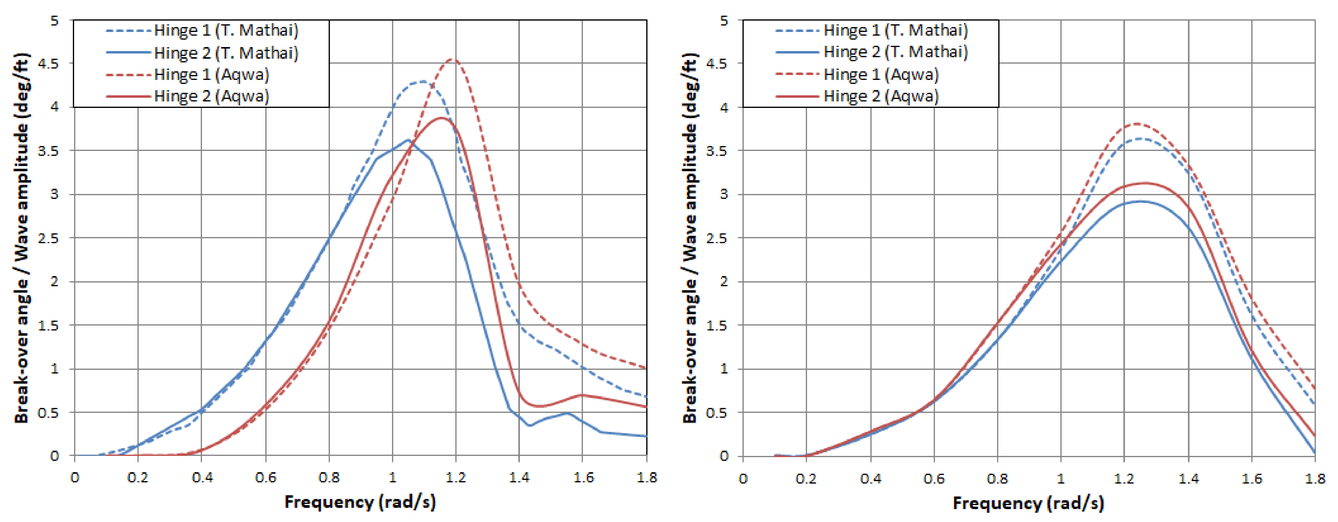
3.4. Tool Validation

The tool functionality was verified through a comparison, in which the triple modular assembly previously studied by Mathai [66] was simulated in Ansys AQWA, and the hinged body analysis tool was then applied. The triple modular assembly was modelled with the hinge connections restraining the motions in all the modes except the set of global modes and relative pitch modes.
The breakover angles are presented for a modular assembly (three 80-foot by 48-foot by 2.7-foot draft hinges end-to-end with a 2-foot gap between the ends). These concern a set of axes with the same orientation as the global axes of Figure 3 but with the origin located at the water level below the centre of gravity of each module. The depth was taken as 50 feet. The hinges were located at a height of 3.9 feet above the water level. Only the forward port quarter of the ensemble was discretised, owing to the two geometric symmetry planes and a reasonable choice of mode shapes.
Computations were repeated for a series of frequencies ranging from 0.05 radians per second to 1.8 radians per second (see Figure 4).
Figure 4 shows that the results had a little variation in phase and amplitude for the relative motion. The maximum difference was less than 0.5 deg/ft. Nevertheless, the software simulation was slightly shifted. This misalignment stemmed from some minor assumptions about the device configuration and numerical damping models due to the lack of data in the analysis performed by Mathai [66].

4. Results for the Nenuphar Multi-Float System Configuration

The time-domain analysis was performed with a first-order Stokes wave theory or Airy wave theory. The analysis was recorded for a long duration series [67,68], with a ramping time of 18 s as a function of the device dimensions. The results from the numerical study made in Ansys AQWA are presented in Table 2. The study was performed in a numerical field 81 m wide, 91 m long and with a water depth of 1000 m. The main characteristics of the device are shown in Table 1. The origin of the x and z-axes is the central body. The centre of mass position is denoted by xG, zG. The ballast comprised 234 tonnes. This ballast is distributed uniformly within the structures themselves to ensure the correct distribution of weights.
This study was performed for three incident waves’ directions covering the device’s main angles of wave incidence. Therefore, the alignments of bodies 4 and 1 were at 0, 15 and 30 degrees with the incoming waves (see Figure 5). The results related to the hinge rotation and heave motion of the central body were analysed. Moreover, the power extracted from the lateral and central bodies’ motions, heave and pitch, respectively, were also analysed. Finally, an increase in the wave amplitude explained the WEC response.
Figure 6 shows the heave motion and rotations of the WEC bodies for 0 degrees of incident wave conditions. Figure 6a shows the heave motion amplitude of the wave energy converter for a regular wave of amplitude 0.5 m and period of 4.8 s. It is quite relevant to observe that the higher motion amplitudes were localised in the bodies with the form of 60 degrees with the incoming wave, i.e., bodies 3 and 5 and bodies 2 and 6, respectively, followed by a central body and bodies 1 and 4, in descending order of importance. This response was because the bodies in the perpendicular direction to the incident wave (in this case, 3– and 2–6) were coupled to the central body as if they were a single body and with little rotation of the hinges. However, the bodies whose hinges were perpendicular to the wave were identified with a smaller movement due to the effect of the flap and the bodies of the intermediate term of the WEC.
Figure 6b presents the body hinge angles. Different conclusions were obtained from the figure where the heave motions of the WEC bodies are shown. Here, maximum hinge rotation was observed in bodies 4 and 1, situated at 0 degrees concerning the incident waves. Then, the symmetrical bodies 3–5 and 2–6 had a minor rotation angle due to their position concerning the incoming wave. Some variations concerning the rotation angles of the hinges in the symmetrical bodies were observed. The angle of hinge 2 was less than that of hinge 6. This slight variation was due to the rotation effects of the entire system. At the same time, this effect was amplified between hinges 3 and 5.
Figure 7 shows the hinge angles of the bodies obtained from three different directions of incident waves. The horizontal axis is the wave frequency, and the vertical axis is the angle of rotation.
The rotation angles were calculated with the lateral body pitch motion concerning the pitch motion of the central body. The edges of the joints were achieved by orienting the pitch motion of the bodies coupled on the same axis through the previously described code.
With the connections and viscous effects, there was a minimum difference between the rotation angles of the symmetrical bodies with 0 degrees of the incident wave (bodies 3–5 and 2–6) while a maximum deviation of 1.1 degrees was observed between body 4 (first to receive the stream) and body 1 (last to support the wave). This variation between the bodies was due to the attenuation generated by the central body, and bodies 3–5 and 2–6, which were positioned at an angle of +/− 30 degrees concerning the direction of wave propagation.
In Figure 7b, the angle of the incident wave of 15 degrees, forming a non-symmetrical axis to which the lateral bodies described concerning the central body, generated a decoupled response between the bodies.
On the other hand, Figure 7c shows how the bodies were coupled in movement in pairs such that the bodies 4–5, 3–6 and 2–1 described the same behaviour. This similarity was because the angle of the incident wave concerning the body produces the effect of symmetry between all the frames in pairs. Moreover, Figure 7c shows a huge rotation angle in the bodies with angles close to the incident wave direction and a much smaller angle in the body’s perpendicular to that wave, due to the arrangement of the hinges. The rotation was obtained by the imbalances generated by the other lateral bodies in the central body.
In the breakover angles shown in Figure 7a, almost the same peak value was obtained for all pairs of symmetrical hinges and perpendiculars to the incident wave direction at T ≈ 4.8 s (corresponding to an incident wave amplitude of 0.5 m, which was about one third the length of the whole converter). The secondary peak at 2.5 rad/s was related to the effects of the central body pitch motion.
Figure 8 describes the amount of power generated for the three incident wave directions. Based on Figure 8, the piston amplitude and power extracted were proportional to the breakover angle. When the frequency was between 1 and 2.8 rad/s, there was a positive effect on energy generation.
As a result, the tendency in Figure 8 was that when joint 1 was aligned longitudinally with the incident wave, the power generated increased. Nevertheless, the other bodies also produced a significant amount of energy.
Moreover, an investigation into higher wave amplitudes is needed to check the trend. Figure 9 shows the breakover angle data for the hinges between the bodies with a wave amplitude of 1.0 m and 1.5 m, and 0 degrees of incident wave direction.
In the case of bodies 4 and 1, the maximum rotation angle was large, about 1.5 degrees and 2.1 degrees more than in the 0.5-m amplitude wave, respectively. The variations in the rotation angles for the 1.5-m wave amplitude reached double of the initial study value. Similarly, the changes in the hinge angles of the bodies located within +/− 30 degrees, concerning the direction of the incident wave of the positive trend were proportional.
From the results of the time-domain analysis, an analysis was carried out to predict the behaviour of central body motion and power for the same previous conditions. The central body acts as a heave point absorber. Figure 10 shows the heave RAOs and the energy extracted for the incident wave angles of 0, 15 and 30 degrees. The heave RAO decreased with increasing wave frequency, but the peak power period reached its maximum at 1.1 rad/s. On the other hand, when the wave frequency was 2.5 rad/s, the second power peak appeared. The power extracted was less than a conventional heave point absorber due to body characteristics and dimensions plus the effects of hinged bodies.
Figure 11 shows the RAOs for the different amplitudes of waves. The RAOs for the wave amplitudes of 1 m and 1.5 m were proportional.

5. Conclusions

This paper presents the preliminary design and results of a new wave energy converter. The document briefly described the development of the Nenuphar, a floating hinged bodies converter and point absorber. The objective of this study is to evaluate the Nenuphar for an extensive range of regular wave conditions. Hence, the main goals of this study are to:
(i)
Provide proof of the Nenuphar concept;
(ii)
Validate the code that allows for obtaining the rotations of the bodies in the axes not aligned with the principal axes;
(iii)
Obtain a preliminary assessment of the WEC performance;
(iv)
Identify potential issues and analyse the feasibility of constructive solutions;
(v)
Gather numerical data for the optimisation of mathematical models and experimental tests;
The behaviour of the Nenuphar is analysed for different wave conditions (various incident wave directions and wave amplitudes). A relative power of up to 400 W is reached, showing that the Nenuphar is a promising WEC. Conclusions are:
(i)
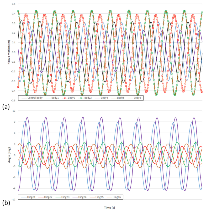
The Nenuphar’s response predominantly occurs in the frequency of incident waves (entire test duration);
(ii)
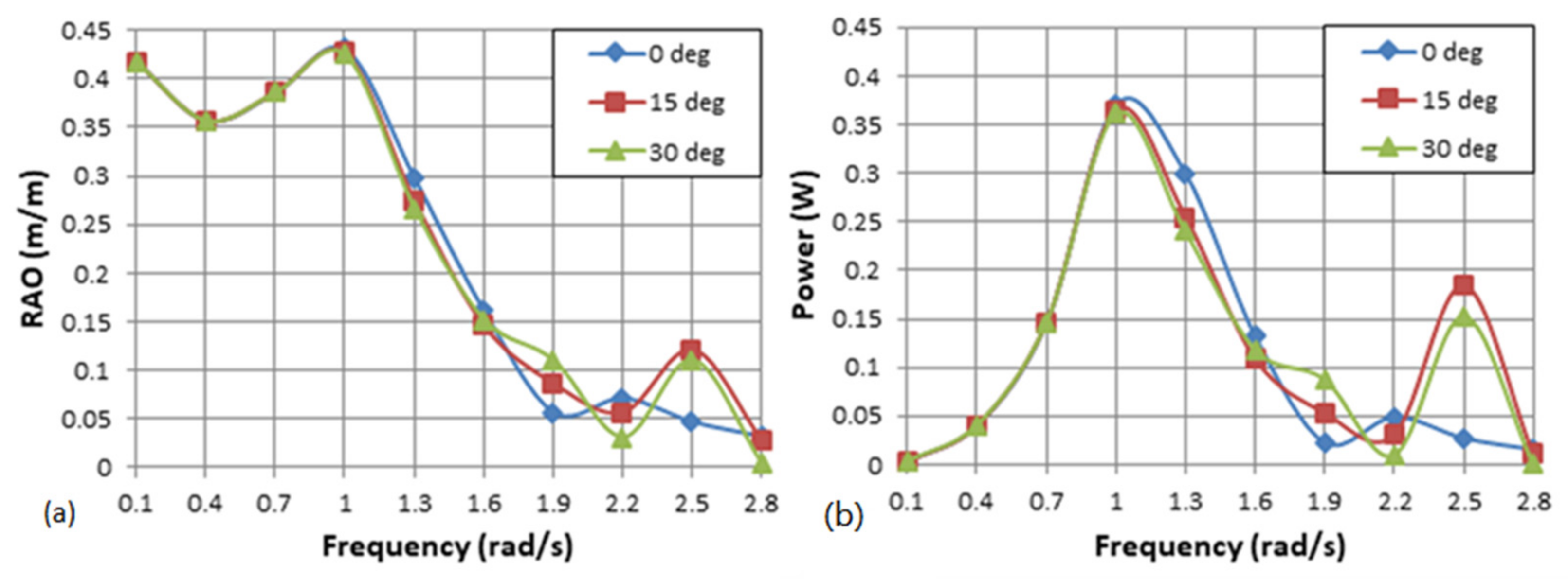
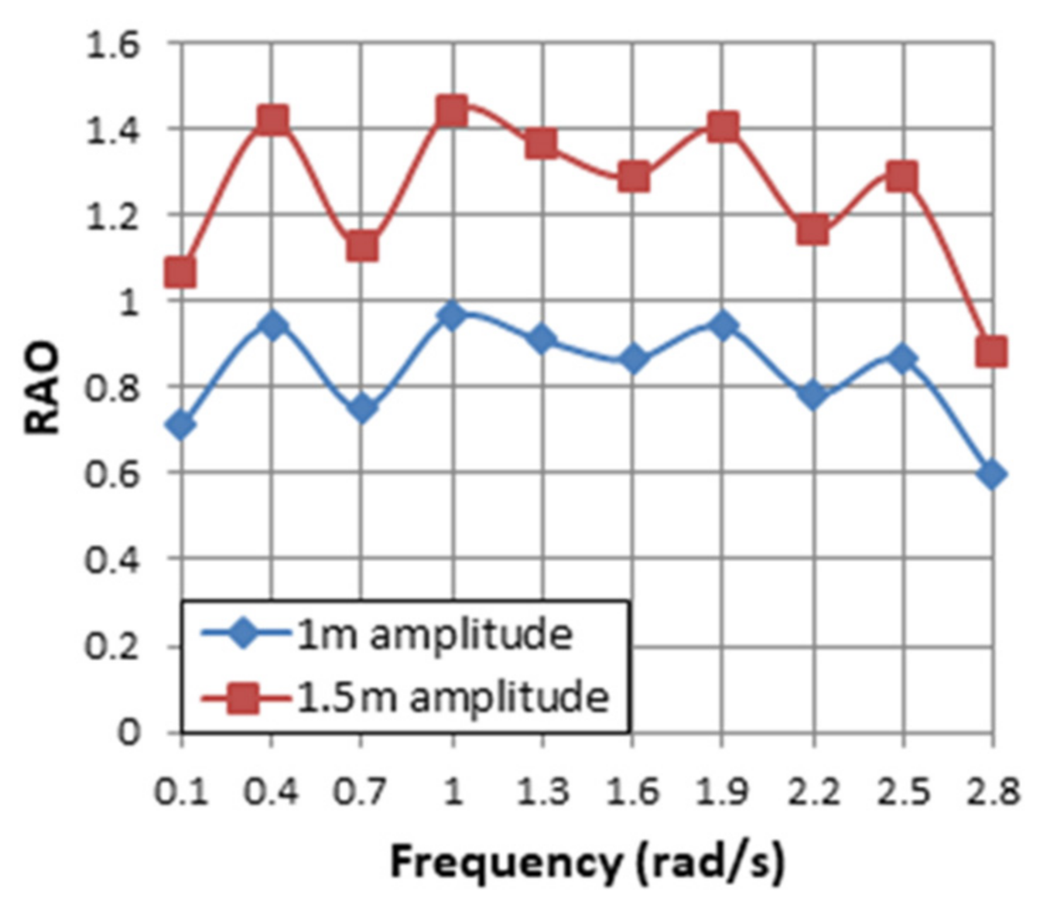
The Nenuphar’s performance strongly depends on the incident wave characteristics;
(iii)
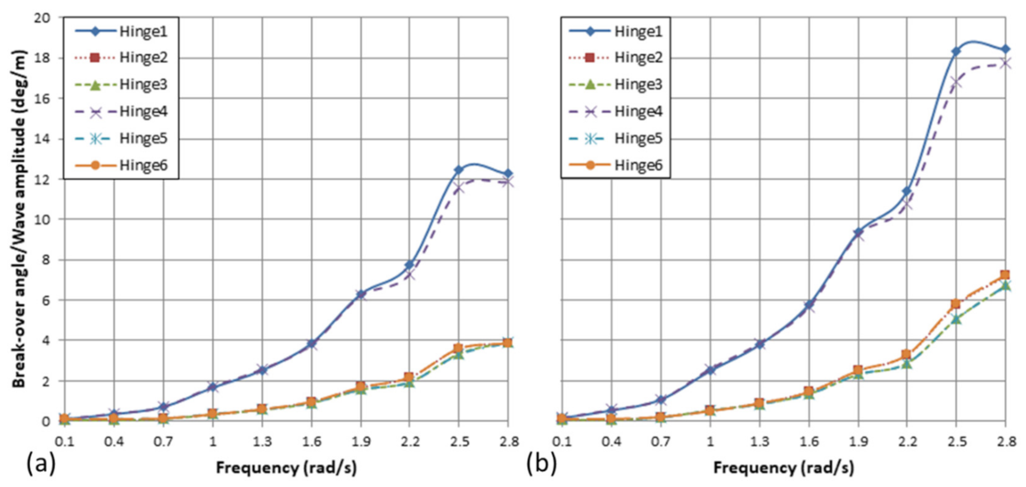
A 30-degree inclination is the most favourable for the tested geometry and wave conditions.
(iv)
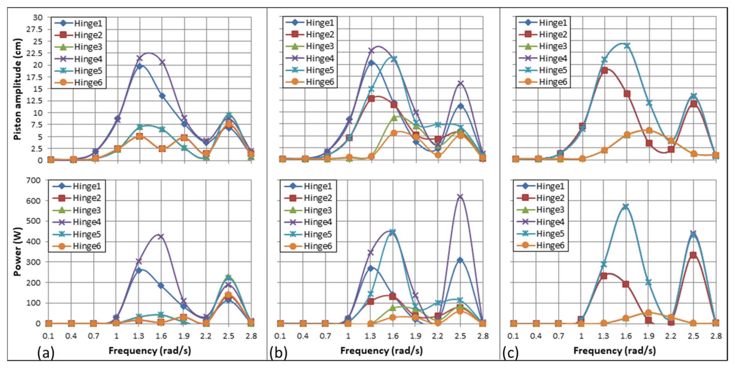
The extraction of continuous energy by the point absorber under all conditions is mainly caused by the movements induced by the lateral body’s rotations.
This device is self-oriented to the incoming wave direction. Some assumptions are introduced in terms of the geometry of the bodies. Despite the simplifications, the behaviour obtained reveals that Nenuphar technology is promising.
Future work is crucial for the proper development of the concept, including:
(i)
A computer simulation that will be conducted for irregular waves, and different dimensions and shapes of floating bodies;
(ii)
An experiment focusing on a hydrodynamic viewpoint, which should deal with the variation in force or load at the connection points;
(iii)
PTO and mooring systems analysis in detail, because although hydrodynamic and mechanical interactions were excluded to simplify this study, it is expected that the converter’s efficiency was not reduced significantly.

Author Contributions

Conceptualization, H.D.; formal analysis, H.D. and J.M.R.; writing—original draft preparation, H.D.; writing—review and editing, C.G.S.; project administration, C.G.S. All authors have read and agreed to the published version of the manuscript.

Funding

This work contributed to the Strategic Research Plan of the Centre for Marine Technology and Ocean Engineering (CENTEC), which was financed by the Portuguese Foundation for Science and Technology (Fundação para a Ciência e Tecnologia (FCT)) under contract UIDB/UIDP/00134/2020.

Institutional Review Board Statement

Not applicable.

Informed Consent Statement

Not applicable.

Data Availability Statement

Not applicable.

Conflicts of Interest

The authors declare no conflict of interest.

References

  1. Khaligh, A.; Onar, O.C. Energy Sources, 3rd ed.; Elsevier Inc.: Amsterdam, The Netherlands, 2011; ISBN 9780123820365. [Google Scholar]
  2. Gonçalves, M.; Martinho, P.; Guedes Soares, C. Wave energy conditions in the western French coast. Renew. Energy 2014, 62, 155–163. [Google Scholar] [CrossRef]
  3. Carballo, R.; Sánchez, M.; Ramos, V.; Fraguela, J.A.; Iglesias, G. Intra-annual wave resource characterization for energy exploitation: A new decision-aid tool. Energy Convers. Manag. 2015, 93, 1–8. [Google Scholar] [CrossRef]
  4. Silva, D.; Bento, A.R.; Martinho, P.; Soares, C.G. High resolution local wave energy modelling for the Iberian Peninsula. Energy 2015, 91, 1099–1112 and 2016, 94, 857–858. [Google Scholar] [CrossRef]
  5. Gunn, K.; Stock-Williams, C. Quantifying the global wave power resource. Renew. Energy 2012, 44, 296–304. [Google Scholar] [CrossRef]
  6. Neill, S.P.; Reza, M.H. Wave Energy. In Fundamentals of Ocean Renewable Energy; E-Business Solutions: HongKong, China, 2018; pp. 107–140. ISBN 9780128104484. [Google Scholar]
  7. Silva, D.; Rusu, E.; Guedes Soares, C. Evaluation of various technologies for wave energy conversion in the Portuguese nearshore. Energies 2013, 6, 1344–1364. [Google Scholar] [CrossRef] [Green Version]
  8. Guedes Soares, C.; Bento, A.R.; Goncalves, M.; Silva, D.; Martinho, P. Numerical evaluation of the wave energy resource along the Atlantic European coast. Comput. Geosci. 2014, 71, 37–49. [Google Scholar] [CrossRef]
  9. Callaway, E. Energy: To catch a wave. Nature 2007, 450, 156–159. [Google Scholar] [CrossRef] [Green Version]
  10. Magana, D.; MacGillivary, A.; Jeffrey, H.; Hanmer, C.; Raventos, A.; Badcock-Broe, A.; Tzimas, E. Wave and Tidal Energy Strategic Technology Agenda; Si Ocean: Brussels, Belgium, 2014; pp. 1–44. [Google Scholar]
  11. Drew, B.; Plummer, A.R.; Sahinkaya, M.N. A review of wave energy converter technology. Proc. Inst. Mech. Eng. Part A J. Power Energy 2009, 223, 887–902. [Google Scholar] [CrossRef] [Green Version]
  12. Waveplam State of the Art Analysis—A Cautiously Optimistic Review of the Technical Status of Wave Energy Technology; Intelligent Energy Europe: Brussels, Belgium, 2009.
  13. Castro-Santos, L.; Martins, E.; Guedes Soares, C. Methodology to calculate the costs of a floating offshore renewable energy farm. Energies 2016, 9, 324. [Google Scholar] [CrossRef] [Green Version]
  14. Castro-Santos, L.; Martins, E.; Guedes Soares, C. Economic comparison of technological alternatives to harness offshore wind and wave energies. Energy 2017, 140, 1121–1130. [Google Scholar] [CrossRef]
  15. Gunnar, M.; Barstow, S.; Kabuth, A.; Pontes, M.T. Assessing the global wave energy potential. In Proceedings of the 29th International Conference on Ocean, Offshore, and Arctic Engineering, Shanghai, China, 6–11 June 2010; pp. 1–8. [Google Scholar] [CrossRef]
  16. Poullikkas, A. Technology Prospects of Wave Power Systems. Electron. J. Energy Environ. 2014, 2, 47–69. [Google Scholar] [CrossRef]
  17. Bernardino, M.; Goncalves, M.; Guedes Soares, C. Marine Climate Projections Toward the End of the Twenty-First Century in the North Atlantic. J. Offshore Mech. Arct. Eng. 2021, 143, 061201. [Google Scholar] [CrossRef]
  18. Yemm, R.; Pizer, D.; Retzler, C.; Henderson, R. Pelamis: Experience from concept to connection. Philos. Trans. R. Soc. A Math. Phys. Eng. Sci. 2012, 370, 365–380. [Google Scholar] [CrossRef] [Green Version]
  19. Falcão, A.F.D.O. Wave energy utilization: A review of the technologies. Renew. Sustain. Energy Rev. 2010, 14, 899–918. [Google Scholar] [CrossRef]
  20. Guedes Soares, C.; Bhattacharjee, J.; Tello, M.; Pietra, L. Review and classification of wave energy converters. In Maritime Engineering and Technology; Guedes Soares, C., Garbatov, Y., Sutulo, S., Santos, T.A., Eds.; Taylor & Francis Group: London, UK, 2012; pp. 585–594. ISBN 9780415621465. [Google Scholar]
  21. Santhosh, N.; Baskaran, V.; Amarkarthik, A. A review on front end conversion in ocean wave energy converters. Front. Energy 2015, 9, 297–310. [Google Scholar] [CrossRef]
  22. Holmukhe, R.M.; Satre, J.V. Wave Energy—A Review. In Proceedings of the International Conference on Science, Engineering & Spirituality (ICSES’2010), Pune, India, 2014; pp. 1–10. [Google Scholar]
  23. Haren, P. Optimal design of Hagen-Cockerall raft, Massachusetts Institute of Technology. Ph.D. Thesis, Massachusetts Institute of Technology, Dept. of Civil Engineering, Cambridge, MA, USA, 1978. [Google Scholar]
  24. Kraemer, D.R.B.; Ohl, C.O.G.; McCormick, M.E. Comparison of experimental and theoretical results of the motions of a McCabe Wave Pump. In Proceedings of the 4th European Wave Energy Conference, Aalborg, Denmark, 19–21 November 2000. [Google Scholar]
  25. Nolan, G.; Catháin, M.; Murtagh, J.; Ringwood, J. Wave-Barge Interaction. In Proceedings of the Fifth European Wave Energy Conference, Cork, Ireland, 17–20 September 2003; Volume 1, pp. 1–8. [Google Scholar]
  26. Henderson, R. Design, simulation, and testing of a novel hydraulic power take-off system for the Pelamis wave energy converter. Renew. Energy 2006, 31, 271–283. [Google Scholar] [CrossRef]
  27. Columbia Power Technologies Technologies. Available online: http://columbiapwr.com/ (accessed on 23 March 2017).
  28. Ruol, P.; Zanuttigh, B.; Martinelli, L.; Kofoed, P.; Frigaard, P. Near-Shore Floating Wave Energy Converters: Applications for Coastal Protection. Coast. Eng. Proc. 2012, 1, 61. [Google Scholar] [CrossRef] [Green Version]
  29. Rusu, E.; Guedes Soares, C. Coastal impact induced by a Pelamis wave farm operating in the Portuguese nearshore. Renew. Energy 2013, 58, 34–49. [Google Scholar] [CrossRef]
  30. Bento, A.R.; Rusu, E.; Martinho, P.; Guedes Soares, C. Assessment of the changes induced by a wave energy farm in the nearshore wave conditions. Comput. Geosci. 2014, 71, 50–61. [Google Scholar] [CrossRef]
  31. Silva, D.; Rusu, E.; Guedes Soares, C. The effect of a wave energy farm protecting an aquaculture installation. Energies 2018, 11, 2109. [Google Scholar] [CrossRef] [Green Version]
  32. Stansby, P.; Carpintero Moreno, E.; Stallard, T.; Maggi, A. Three-float broad-band resonant line absorber with surge for wave energy conversion. Renew. Energy 2015, 78, 132–140. [Google Scholar] [CrossRef]
  33. Gaspar, J.F.; Stansby, P.K.; Calvário, M.; Guedes Soares, C. Hydraulic Power Take-Off concept for the M4 Wave Energy Converter. Appl. Ocean Res. 2021, 106, 102462. [Google Scholar] [CrossRef]
  34. Gaspar, J.F.; Calvário, M.; Kamarlouei, M.; Guedes Soares, C. Power take-off concept for wave energy converters based on oil-hydraulic transformer units. Renew. Energy 2016, 86, 1232–1246. [Google Scholar] [CrossRef]
  35. Gaspar, J.F.; Kamarlouei, M.; Sinha, A.; Xu, H.; Calvário, M.; Faÿ, F.X.; Robles, E.; Guedes Soares, C. Analysis of electrical drive speed control limitations of a power take-off system for wave energy converters. Renew. Energy 2017, 113, 335–346. [Google Scholar] [CrossRef]
  36. Gaspar, J.F.; Calvário, M.; Kamarlouei, M.; Guedes Soares, C. Design tradeoffs of an oil-hydraulic power take-off for wave energy converters. Renew. Energy 2018, 129, 245–259. [Google Scholar] [CrossRef]
  37. Floating Power Plant Products. Available online: http://www.floatingpowerplant.com/ (accessed on 23 March 2017).
  38. Marquis, L.; Kramer, M.M.; Kringelum, J.; Chozas, J.F.; Helstrup, N.E. Introduction of Wavestar Wave Energy Converters at the Danish offshore wind power plant Horns Rev 2. 4th Int. Conf. Ocean Energy 2012, 2, 2–7. [Google Scholar]
  39. Kamarlouei, M.; Gaspar, J.F.; Calvario, M.; Hallak, T.S.; Mendes, M.J.G.C.; Thiebaut, F.; Guedes Soares, C. Experimental study of wave energy converter arrays adapted to a semi-submersible wind platform. Renew. Energy 2022, 188, 145–163. [Google Scholar] [CrossRef]
  40. Kamarlouei, M.; Gaspar, J.F.; Calvario, M.; Hallak, T.S.; Mendes, M.J.G.C.; Thiebaut, F.; Guedes Soares, C. Experimental analysis of wave energy converters concentrically attached on a floating offshore platform. Renew. Energy 2020, 152, 1171–1185. [Google Scholar] [CrossRef] [Green Version]
  41. Falnes, J.; Hals, J. Heaving buoys, point absorbers and arrays. Philos. Trans. A. Math. Phys. Eng. Sci. 2012, 370, 246–277. [Google Scholar] [CrossRef] [Green Version]
  42. Dick, W. Wave Energy Converter. Canada Patent 2,642,547, 20 December 2001. [Google Scholar]
  43. Ocean Power Technologies PowerBuoy. Available online: http://www.oceanpowertechnologies.com/ (accessed on 23 March 2017).
  44. Beatty, S.J.; Hall, M.; Buckham, B.J.; Wild, P.; Bocking, B. Experimental and numerical comparisons of self-reacting point absorber wave energy converters in regular waves. Ocean Eng. 2015, 104, 370–386. [Google Scholar] [CrossRef]
  45. Leijon, M.; Boström, C.; Danielsson, O.; Gustafsson, S.; Haikonen, K.; Langhamer, O.; Strömstedt, E.; Stålberg, M.; Sundberg, J.; Svensson, O.; et al. Wave energy from the north sea: Experiences from the lysekil research site. Surv. Geophys. 2008, 29, 221–240. [Google Scholar] [CrossRef] [Green Version]
  46. Seabased, A.B. The Seabased Solution. Available online: http://www.seabased.com/en/ (accessed on 23 March 2017).
  47. Rahm, M. Underwater Substation System for Wave Energy Converters; Uppsala University: Uppsala, Sweden, 2010. [Google Scholar]
  48. Elwood, D.; Schacher, A.; Rhinefrank, K.; Prudell, J.; Yim, S.; Amon, E.; Al, E. Numerical modelling and ocean testing of a direct-drive wave energy device utilizing a permanent magnet linear generator for power take-off. In Proceedings of the ASME 2009 28th International Conference on Ocean, Offshore and Arctic Engineering, Honolulu, HI, USA, 31 May–5 June 2009. OMAE2009-79146. [Google Scholar]
  49. Brekken, T.K.A.; Von Jouanne, A.; Han, H.-Y. Ocean wave energy overview and research at Oregon State University. In Proceedings of the 2009 IEEE Power Electronics and Machines in Wind Applications, Lincoln, NE, USA, 24–26 June 2009. [Google Scholar] [CrossRef]
  50. Oscilla Power Wave Energy. Available online: http://oscillapower.com/ (accessed on 23 March 2017).
  51. Mundon, T.R.; Nair, B. Optimization of a Magnetostrictive Wave Energy Converter. Gd. Renew. Energy 2014, 2014, 1–6. [Google Scholar]
  52. Mundon, T.R.; Imamura, J. Optimization of a Magnetostrictive Wave Energy Converter. In Proceedings of the Grand Renewable Energy, Tokyo, Japan, 27 July–1 August 2015. [Google Scholar]
  53. López, I.; Andreu, J.; Ceballos, S.; Martínez De Alegría, I.; Kortabarria, I. Review of wave energy technologies and the necessary power-equipment. Renew. Sustain. Energy Rev. 2013, 27, 413–434. [Google Scholar] [CrossRef]
  54. Bozzi, S.; Miquel, A.M.; Antonini, A.; Passoni, G.; Archetti, R. Modeling of a point absorber for energy conversion in Italian seas. Energies 2013, 6, 3033–3051. [Google Scholar] [CrossRef] [Green Version]
  55. Xu, S.; Wang, S.; Guedes Soares, C. Review of mooring design for floating wave energy converters. Renew. Sustain. Energy Rev. 2019, 111, 595–621. [Google Scholar] [CrossRef]
  56. ANSYS Hydrodynamic Analysis with Ansys AQWA (Version 17.2). Available online: https://www.ansys.com/products/structures/ansys-AQWA (accessed on 23 March 2017).
  57. Paparella, F. Modeling and Control of a Multibody Hinge-Barge Wave Energy Converter. Ph.D. Thesis, Maynooth University, Maynooth, Ireland, 2017. [Google Scholar]
  58. Paparella, F.; Ringwood, J.V. Optimal Control of a Three-Body Hinge-Barge Wave Energy Device Using Pseudospectral Methods. IEEE Trans. Sustain. Energy 2017, 8, 200–207. [Google Scholar] [CrossRef] [Green Version]
  59. Mei, C.C.; Stiassnie, M.A.; Stiassnie, M.A.; Yue, D.K.-P. Theory and Applications of Ocean Surface Waves, 3rd ed.; World Scientific Publishing Company: Hackensack, NJ, USA, 2018. [Google Scholar]
  60. Falnes, J. Ocean Waves and Oscillating Systems; Cambridge University Press: Cambridge, UK, 2002; ISBN 0-521-78211-2. [Google Scholar]
  61. Van der Molen, W.; Wenneker, I. Time-domain calculation of moored ship motions in nonlinear waves. Coast. Eng. 2008, 55, 409–422. [Google Scholar] [CrossRef]
  62. Morison, J.R.; Johnson, J.W.; Schaaf, S.A. The Force Exerted by Surface Waves on Piles. J. Pet. Technol. 1950, 2, 149–154. [Google Scholar] [CrossRef]
  63. ANSYS AQWA Workbench. Available online: https://www.ansys.com/ (accessed on 23 March 2017).
  64. Papillon, L.; Costello, R.; Ringwood, J.V. Boundary element and integral methods in potential flow theory: A review with a focus on wave energy applications. J. Ocean Eng. Mar. Energy 2020, 6, 303–337. [Google Scholar] [CrossRef]
  65. Siciliano, B.; Khatib, O. Handbook of Robotics; Springer: Berlin, Germany, 2008; ISBN 9783540239574. [Google Scholar]
  66. Mathai, T. Use of generalized modes in hydrodynamic analysis of multiple bodies. Int. Offshore Polar Eng. Conf. 2000, 396–400. [Google Scholar]
  67. Li, Y.; Yu, Y.H. A synthesis of numerical methods for modeling wave energy converter-point absorbers. Renew. Sustain. Energy Rev. 2012, 16, 4352–4364. [Google Scholar] [CrossRef]
  68. Yu, Y.H.; Tom, N.; Jenne, D. Numerical analysis on hydraulic power take-off for wave energy converter and power smoothing methods. Madrid, Spain, 17–22 June 2018. OMAE2018-78176. [Google Scholar] [CrossRef]
Figure 1. Schematic diagram of an attenuator (left) and point absorber (right) WECs.
Jmse 10 01612 g001
Figure 2. Nenuphar WEC design (perspective view and top view).
Jmse 10 01612 g002
Figure 3. Schematic of the triple modular assembly corresponding to one of the device’s three main axes.
Jmse 10 01612 g003
Figure 4. A comparison of the breakover angles of the triple modular assembly in following seas (left) and quartering seas (right).
Jmse 10 01612 g004
Figure 5. The analysed incident wave directions from a top view of the Nenuphar WEC.
Jmse 10 01612 g005
Figure 6. The (a) heave motion of the bodies and (b) hinge angles of the bodies at time T 4.8 s, an amplitude of 0.5 m and incident wave of 0°.
Jmse 10 01612 g006
Figure 7. The hinge rotation angle at: (a) 0 degrees of incident wave direction; (b) 15 degrees of incident wave direction; and (c) 30 degrees of incident wave direction.
Jmse 10 01612 g007
Figure 8. The piston amplitude and power extracted at: (a) 0 degrees of incident wave direction; (b) 15 degrees of incident wave direction; and (c) 30 degrees of incident wave direction.
Jmse 10 01612 g008
Figure 9. The hinge rotation angle at: (a) 1 m of wave amplitude and (b) 1.5 m of wave amplitude.
Jmse 10 01612 g009
Figure 10. The heave motion (a) RAO and (b) power with 0, 15 and 30 degrees of incident wave direction on the central body.
Jmse 10 01612 g010
Figure 11. The RAO and power extracted by the central body with 0, 15 and 30 degrees of incident wave direction.
Jmse 10 01612 g011
Table 1. Main parameters of initially designed Nenuphar in full scale.
Central BodyLateral Bodies
Length (m)13.015.0
Width (m)15.07.5
Spacing between rafts (m)1.301.30
Draft (m)0.70.7
Displacement mass (kg)98,718.7455,625.0
Ballast (kg)43,993.2190,014.7
MaterialHY-80 (Steel)HY-80 (Steel)
Thickness (m)0.020.02
Density (kg/m3)77467746
Radius of gyration, Kxx (m), Roll3.42.2
Radius of gyration, Kyy (m), Pitch3.44.3
Radius of gyration, Kzz (m), Yaw4.84.8
Centre of gravity, xG (m)015.2/7.7/−7.7/15.3/−7.7/7.7
Centre of gravity, zG (m)00/13.2/13.2/0/−13.2/−13.2
KG (m)0.70.7
KB (m)0.30.3
BM (m)27.86.9
GM (m)27.56.6
TPC (m)1.51.2
KG: centre of gravity above baseline; KB: centre of buoyancy above baseline; BM: metacentric radius; GM: metacentric height above centre of gravity; TPC: tonnes per centimetre immersion; Kxx, Kyy, Kzz: Cartesian coordinate system.
Table 2. Some inputs used in the Ansys AQWA simulations.
ParameterValue
Water density (kg/m3)1000
Water depth (m)1000
Water size, x (m)91
Water size, y (m)86
Mooring cable stiffness (N/m)4000
Mooring typeCatenary
Mesh maximum size (Hz)0.495
Time analysis (s)2700
Time step (s)0.1
Ramping time (s)18
Publisher’s Note: MDPI stays neutral with regard to jurisdictional claims in published maps and institutional affiliations.

