1. Introduction
The shipbuilding industry relies on a strict and detailed set of rules and regulations, aimed at ensuring high safety standards. Therefore, the introduction of novel and unusual structural solutions has to be supported by reliable design methodologies and consistent experimental evidence. Small-scale experimental investigations are essential to assess material properties, mechanical response of some structural details or local collapse modes, which can support the development of design procedures and numerical analysis. The mechanical strength estimation, obtained by laboratory tests on specimens, is of limited practical use if the obtained results cannot be extended, with a certain degree of reliability, from the specimen to the real structure or component. Complex and innovative structural solutions destined to applications requiring high safety levels, such as ship hulls and structures, needs to be analysed and verified by means of large-scale experimental analysis [
1,
2]. In recent years, the search for novel solutions in shipbuilding has been boosting the push for achieving “green” targets and increasing competitiveness. Therefore, large-scale testing, despite being expensive and time consuming, plays a crucial role in promoting a wider use of sustainable and technologically advanced solutions for marine structures.
Among possible solutions combining both structural reliability and low environmental impact, sandwich structures, made of sustainable materials such as aluminium, are an attractive opportunity for shipbuilding industry [
3,
4,
5], as a result of their intrinsic features of low-density and high strength to weight and stiffness-to-weight ratios. Palomba et al. [
3] reviewed the marine applications of sandwich structures. Among the lightweight and green sandwich structures, aluminium honeycomb sandwich (AHS) panels are a good solution as an alternative for conventional marine structures. One of the first recorded applications for AHS in the marine field was the hydroplane built by Pay ‘n Pak, where aluminium honeycomb panels where used as structural elements for bulkheads, decks and the hull [
6]. It is also reported in [
7] that honeycomb sandwich panels were already being used in the late 1990s from the US Navy for bulkheads to reduce the ship weight above the water line in order to enhance manoeuvrability and stability. More recently, Zhao et al. [
8] suggested a honeycomb-based steel sandwich structures as a feasible solution to improve the crashworthiness of ships’ sides subjected to lateral collision. In the configuration used in their study, which was exclusively numerical, honeycomb cells run parallel to the ship side. They found an improvement in terms of crashworthiness, compared to the traditional ship structure, but they recommended additional investigations to optimise the design and avoid excessive weight increase. The potentialities of AHS as impact-absorbing structures for marine applications were further investigated in Refs. [
9,
10], which suggested aluminium honeycomb sandwich structures to protect polar ships and general marine structures from floating ice collisions. Both numerical and experimental analysis, involving actual ice wedge and plain AHS panels, were performed with the aim of collecting data and lay the foundations for possible future designs. Another use of AHS in marine structure was suggested in [
11], where a design procedure for was proposed and then further developed in [
12], for the application of AHS as a replacement for the conventional steel inner side shell of the cargo hold of a bulk carrier. Despite the attention toward lightweight structural solutions increasing in the marine industry, AHS has not gained a stable role in shipbuilding practice so far. Consistent theoretical and experimental information are still not available to support reliable design, especially when considering the integration of AHS in complex structures and under complex loading conditions. Indeed, the great majority of scientific literature on AHS is concerned with experimental or numerical analysis on small samples subjected to simple loading conditions.
A major issue to solve in order to endorse a consistent and extensive use of sustainable sandwich structures in shipbuilding concerns the techniques to connect them to other sandwich parts and to the main structures [
13,
14,
15]. Joining techniques in shipbuilding present challenges [
16] also in relation to the use of lightweight alloys, such as aluminium, whose connection with other parts made of different metals (e.g., steel) requires suitable methods. Among those, explosion welding is recognised as one of the most advanced and efficient techniques to join dissimilar metals. The interest towards the use of explosion-welded joints in shipbuilding is testified by numerous experimental investigations focused on different loading conditions [
17,
18,
19,
20,
21]. A more extensive use of explosion-welded joints would support an easier integration of lightweight alloys in shipbuilding, whose most direct advantage is to obtain structures lightening. Aluminium alloys are the most common lightweight alloys for shipbuilding, as a result of their mechanical properties and their resistance to corrosion [
18]; therefore, Al/Fe explosive welded joint type is the predominant one for marine industry. Recent research works focused on the development of thinner transition joints than those commonly available [
17], aimed at increasing the possible applications of similar joints. The effect of heat treatments produced by welding other parts on transition joints is also crucial to avoid damages to the joint, and hence, suitable welding technologies and methodologies should be employed, as observed in [
22]. The growing attention of the marine industry towards Al/Fe transition joints is also proved by research focused on corrosion [
18,
23,
24,
25]. Corigliano and Crupi [
16] reviewed the approaches for predicting the fatigue life of welded marine joints and structures. The fatigue approaches were generally applied to small welded specimens even if some of them [
26,
27,
28] could be applied to large-scale structures, so full-scale tests are required for their validation and for the fatigue assessment of the real structures. Despite the literature on explosion-welded joints flourishing, it is predominantly focused on small-scale samples, usually not connected to other components. Therefore, investigations on bimetallic joints included in a realistic context with full-scale dimensions are not commonly performed, but their relevance for a better understanding of joints response is undeniable.
The scenario depicted above highlights that the introduction in shipbuilding of aluminium-based sandwich structures combined with advanced joining techniques should be supported by extensive and reliable large-scale experimental investigations. The current paper is therefore focused on the experimental analysis of a large-scale structure for marine applications, which includes a lightweight sustainable sandwich component and Al/Fe explosion-welded joints to provide connections with the main structural parts. A case study representing a plausible application of sandwich structures in shipbuilding was identified, designed and tested. The selected illustrative example involves a ship balcony overhang where an AHS panel was used as the balcony floor. Al/Fe explosion-welded joints, investigated by some of the authors [
20] by means of small-scale testing and finite element analyses, were introduced as connections between the aluminium flooring and the steel ship’s side, represented by a steel wall. The main features of the AHS panels were obtained according to a comparative design approach developed in a previous work [
11], where AHS were suggested as a replacement for a similar structure—designed and tested by Kharghani and Soares [
29,
30]—including a GFRP (glass-fibre-reinforced plastics)—balsa sandwich and a full steel support frame. Some prototypes of the selected structures were manufactured and destined to full-scale testing with the aim of assessing the feasibility of the suggested solution, highlighting potential criticalities, and identifying the collapse modes of the whole structure. The ship balcony was subjected to bending loading applied at its free extremity in both quasi-static and cyclic conditions. The failure modalities were analysed by visual inspection and real time radiography.
The full-scale experimental testing allowed the identification of the mechanical response of such a complex structure, both under static and cycling bending loading. Similar investigations on a full-scale structure, involving several components and innovative joining solutions, such as explosion-welded joints, are seldom reported in scientific literature. The obtained data, in addition to highlighting the feasibility of similar structures, would be useful to support future design and numerical analysis of similar marine structures.
2. Preliminary Design of the Ship Balcony Overhang
The prototype structure subjected to full-scale experimental investigation was the result of a design procedure suggested in a previous work [
11], which is summarised in this section with the aim of stating the context of the study.
The premises of the developed methodology were to replace the GFRP-balsa sandwich panel used in a ship balcony overhang designed and tested in Refs. [
29,
30], with an alternative lightweight sandwich panel made with more sustainable materials, such as AHS. Therefore, the design procedure was limited to the replacement of the GFRP sandwich panel with a lighter and more sustainable alternative. In general, sandwich structures are an excellent solution for parts and components mainly subjected to bending loading, since their basic principle is to maintain a low weight, while ensuring a high bending stiffness, according to the same principle of I-beams. AHS solutions in particular, as well as providing a more sustainable material, have the potential to provide significant weight savings, if compared to GFRP-based alternatives, as a result of their high stiffness-to-weight ratio.
The width b and the length L of the original sandwich panel were kept unvaried, i.e., equal to 750 and 1050 mm, respectively. The design procedure included the following steps:
The bending stiffness (
D) of the original sandwich structure was selected as an equivalent parameter to guide the identification of an alternative sandwich structure, considering that such property is often a crucial property for the design phase. The geometry of the sandwich panel suggested that the bending stiffness had to be evaluated according to the plate theory, using the well-known theoretical formulation for sandwich panel cylindrical bending [
31]. The obtained bending stiffness resulted equal to 3.15 × 10
7 N mm, which is the target value for the replacing structure.
A comparison among several alternative sandwich panels (e.g., AHS, GFRP-PVC, aluminium foam sandwich, etc.) was performed by means of materials charts reporting the bending stiffness against other properties (e.g., core thickness, overall panel density, areal density). AHS was identified as the most convenient solution to achieve both weight and volume reduction. The compatibility with the marine environment was considered by selecting a proper aluminium alloy for the subsequent steps and, in particular, an AA 3003 for the honeycomb core and an AA 5754 for the skins.
The main design variables, such as core and skin thickness and core density, were obtained by combining the benchmark bending stiffness with other relevant objectives, such as mass minimisation for the considered case study. A 50% mass reduction in comparison to the original structure was considered a feasible goal; hence, a mass of around 7–8 kg was set as an additional objective for replacing the AHS. Similar weight savings are achievable as a result of the high stiffness-to-weight ratio which is typical of AHS structures.
Following the identification of the main features for the AHS panel, a concept for the supporting frame was suggested. The frame included two aluminium plates to clamp the AHS panel and Al/Fe explosion-welded joints to connect the aluminium plates to a steel wall. Differently from the reference balcony structure, which was entirely made of steel, the aluminium supporting plates produce a further mass saving. Therefore, the presence of bimetallic joints is essential to provide a reliable connection between lightweight components and steel parts. The details of the balcony structures are reported in the following section.
3. Experimental Investigation: Prototype and Methods
The design methodology summarised in
Section 2 led to the identification of an equivalent aluminium honeycomb sandwich panel—here named ‘AHS#1’. The AHS features reported in Ref. [
11] were partially revised according to the availability of commercial AHS panels and are summarised in
Table 1. The experimental analysis also included another sandwich panel, named ‘AHS#2’, with a lower density core in comparison to AHS#1, in order to further investigate the potentialities of AHS for structural applications and to analyse the effect of cell size on the overall response of such a complex structure. AHS#2 features as well as the properties of the reference GFRP-balsa-steel structure are also summarised in
Table 1.
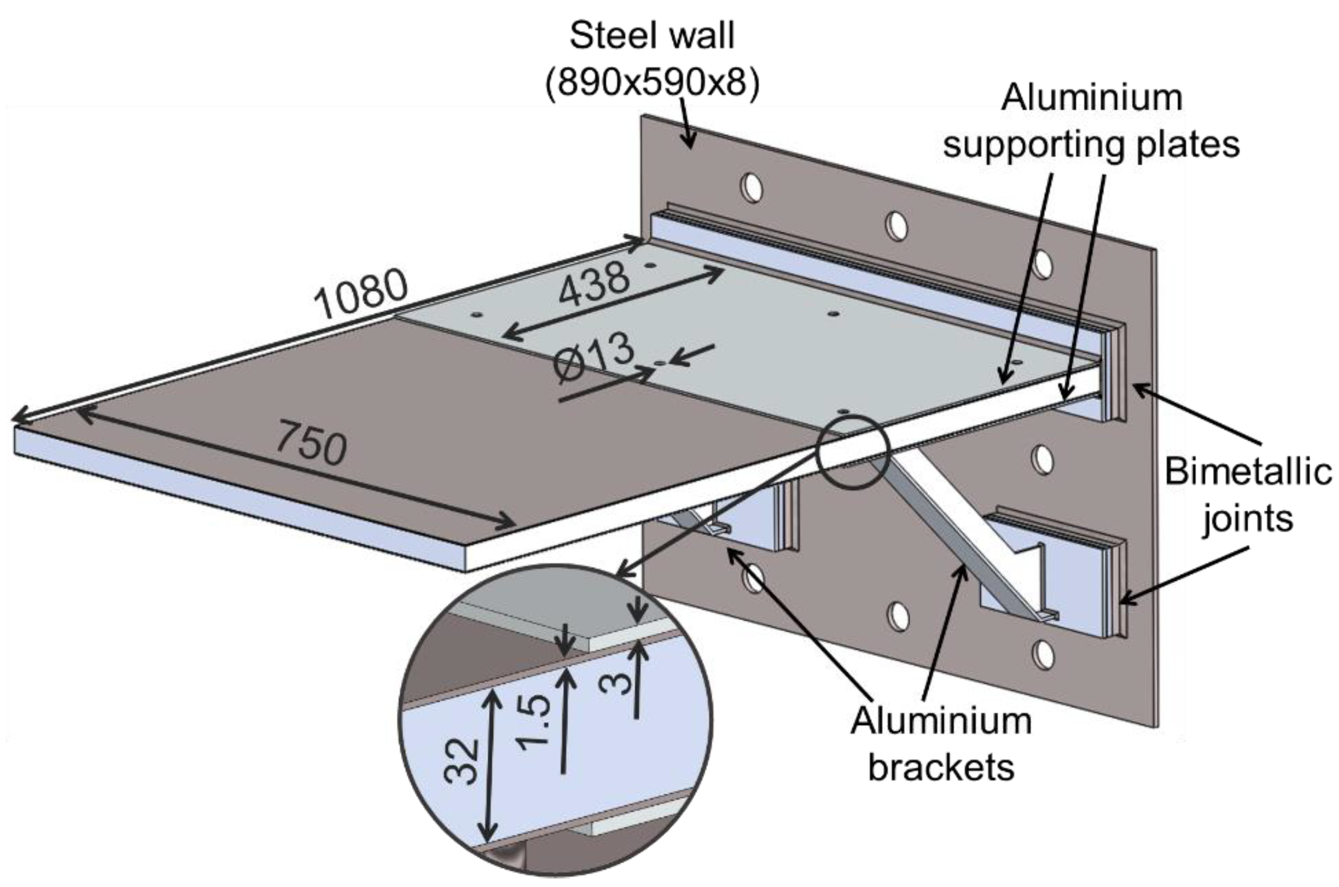
The supporting balcony frame is depicted with its main features in
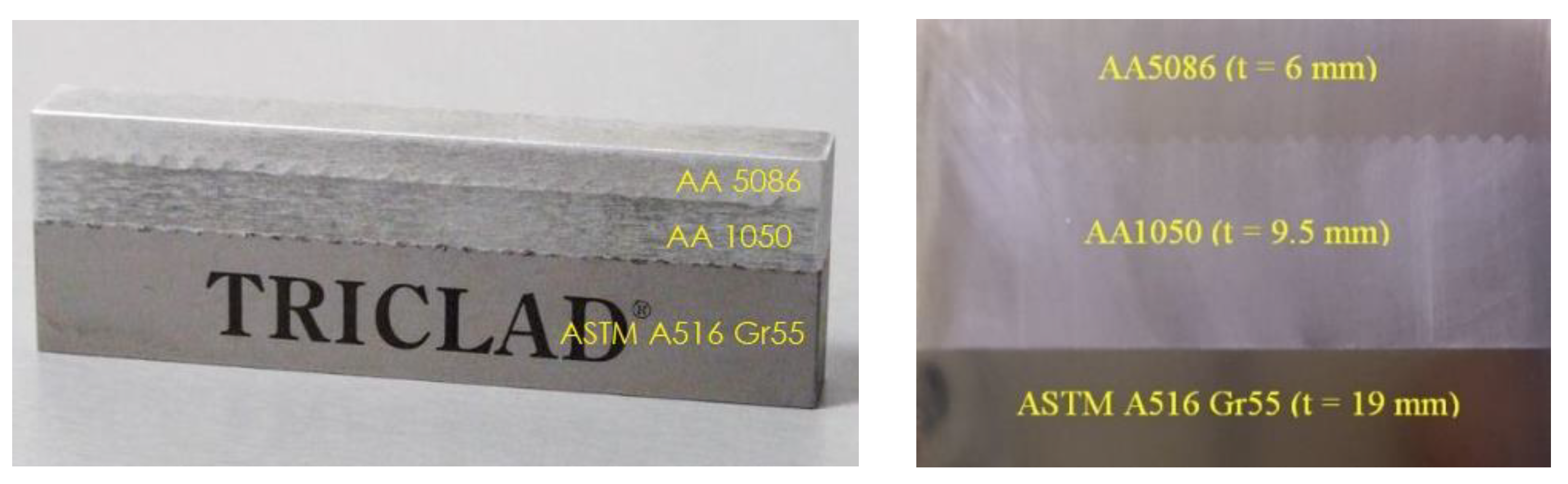
Figure 1. It includes the following: two 3 mm-thick aluminium plates, two aluminium brackets welded to the bottom plate aimed at improving the structural stability, and likewise, the reference structure and Al/Fe explosion-welded transition joint, manufactured by TriClad, to provide the connection between the aluminium plates and brackets with a steel wall. A bolted connection, obtained with six M13 bolts, was chosen to bond the sandwich panel and the supporting plates, allowing at the same time a simple substitution of the panel to be tested. The welded joint, showed in
Figure 2, consists of ASTM A516 Gr55 structural steel, clad by explosion welding with AA5086 aluminium alloy with an intermediate layer of AA1050 commercial pure aluminium. The balcony frame has an estimated equal to 63 kg, against the 135 kg of the reference structure, which was entirely made of steel.
The main mechanical properties of the aluminium honeycomb sandwich panels and the bimetallic explosion-welded joint are reported, respectively, in
Table 2 and
Table 3. The properties of the AHS were derived from the datasheet of the manufacturer, whereas the properties of the bimetallic joint are those reported in Refs. [
32,
33], where some of the authors calculated them from hardness measurements, in order to take into consideration the effect on mechanical properties of the hardening produced by the explosion welding process.
The described structure was tested at the CERISI laboratories of the University of Messina, which is provided with an ITALSIGMA testing portal frame for full-scale investigations. The overhang structure was bolted to a fixed reaction block with six M36 bolts.
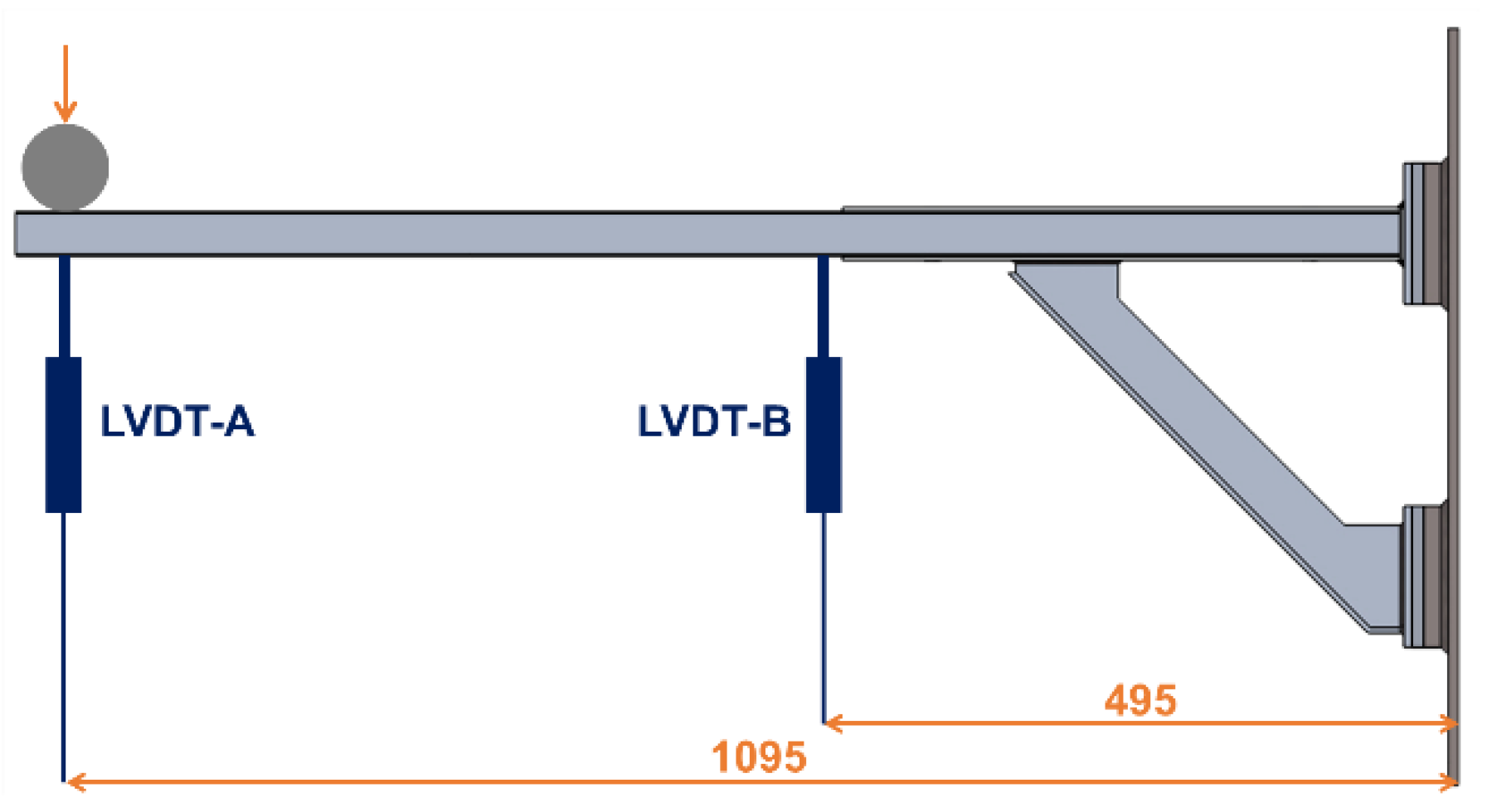
The experimental investigation included both quasi-static and fatigue tests, performed with a 100 kN servo-hydraulic actuator. During quasi-static tests the load was applied at a constant rate of 10 mm/min at the free extremity of the balcony by means of a steel cylinder with the diameter equal to 60 mm and 950 mm long. Two LVDTs were placed under the panel, at the points A and B identified in
Figure 3, along the structure’s longitudinal axis of symmetry.
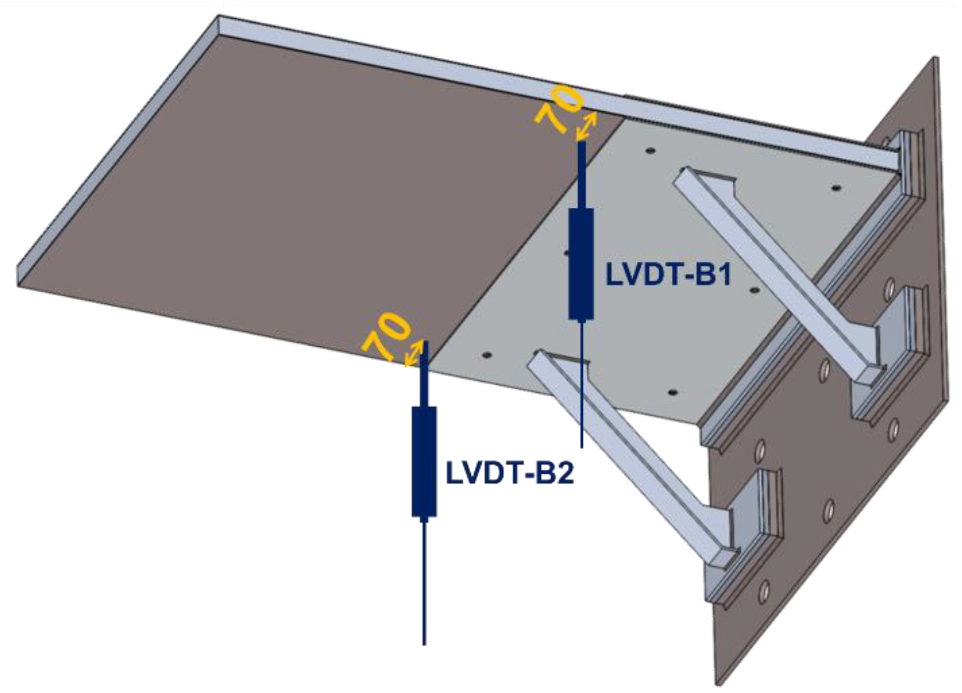
Fatigue tests were performed under displacement control conditions. Preliminary fatigue analyses were performed varying the displacement amplitude, with the aim of evaluating the cyclic hardening, the load–displacement hysteresis, and the sandwich panel collapse modes. Once such information had been collected, a fatigue test was performed at a constant displacement range. For the second fatigue test, two LVDTs were placed at the same longitudinal position of LVDT-B, but on both sides of the panel, as shown in
Figure 4, with the aim of evaluating the possible onset of torque stresses during the test. More details on fatigue tests conditions are reported in
Section 5.
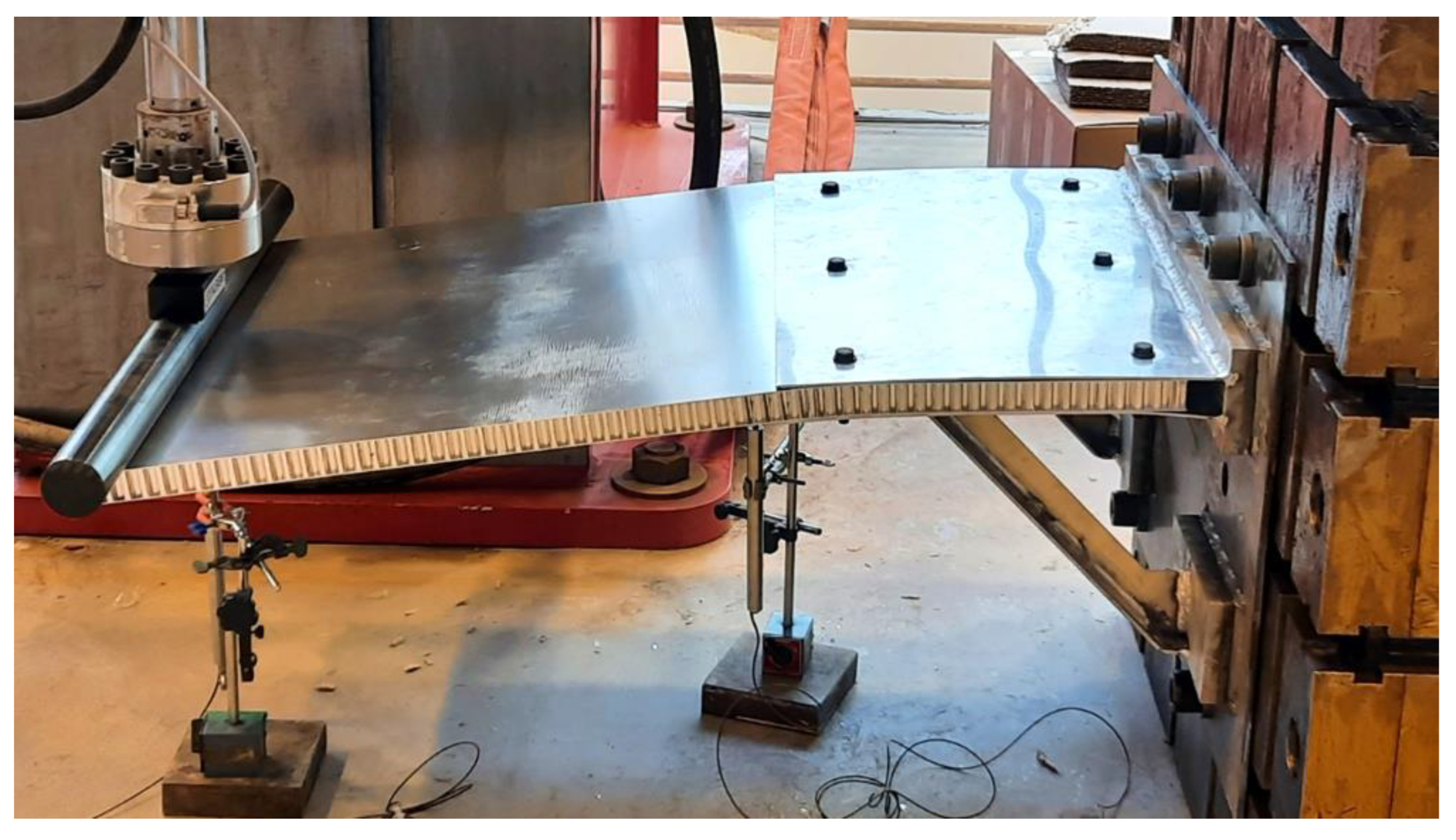
The experimental setup is displayed in
Figure 5.
4. Experimental Results
4.1. Quasi-Static Tests
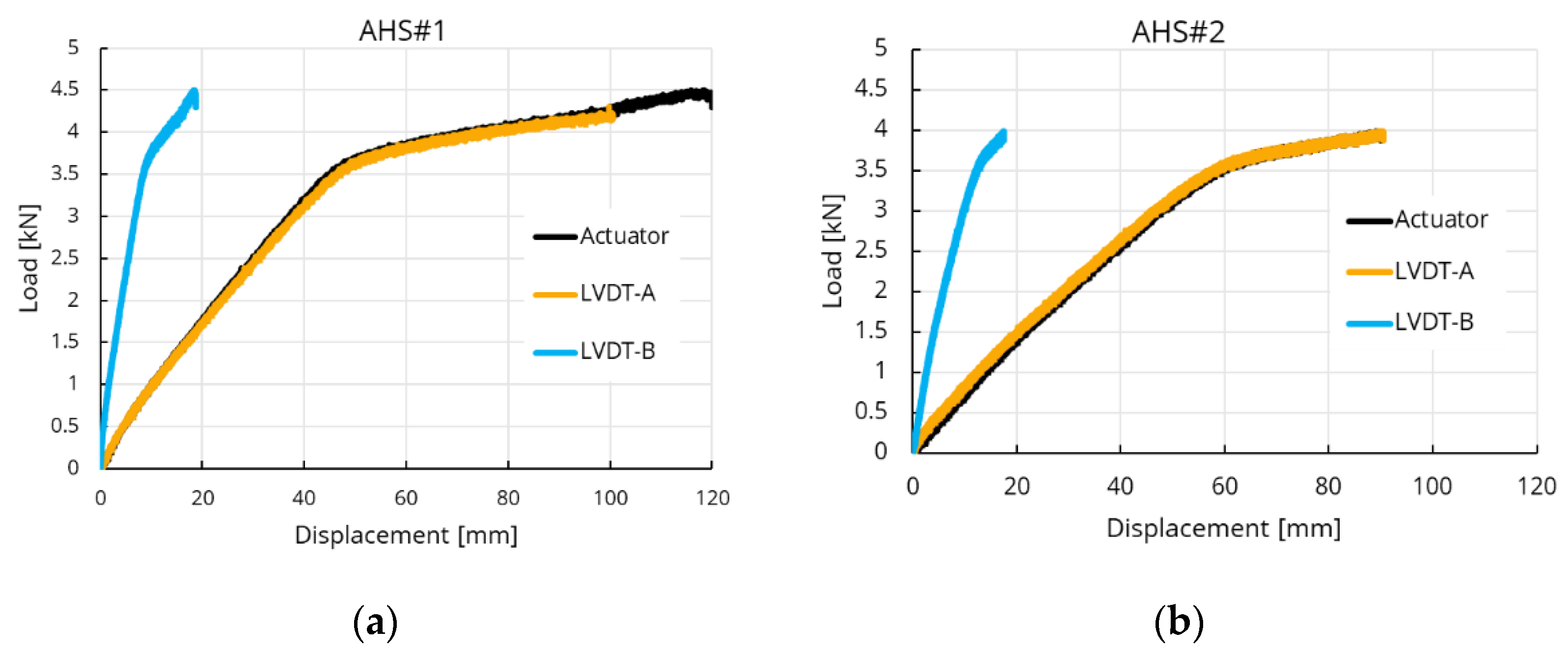
Experimental load–displacement curves for both AHS#1 and AHS#2 are reported in
Figure 6.
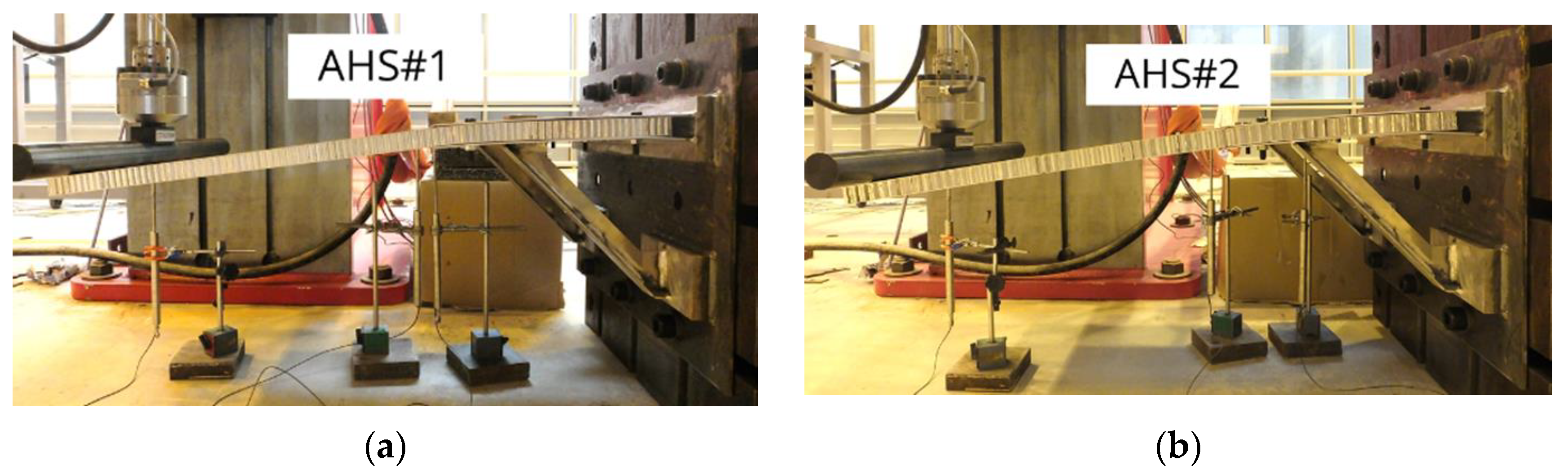
Figure 7 shows the balconies at the maximum displacement obtained during quasi-static testing.
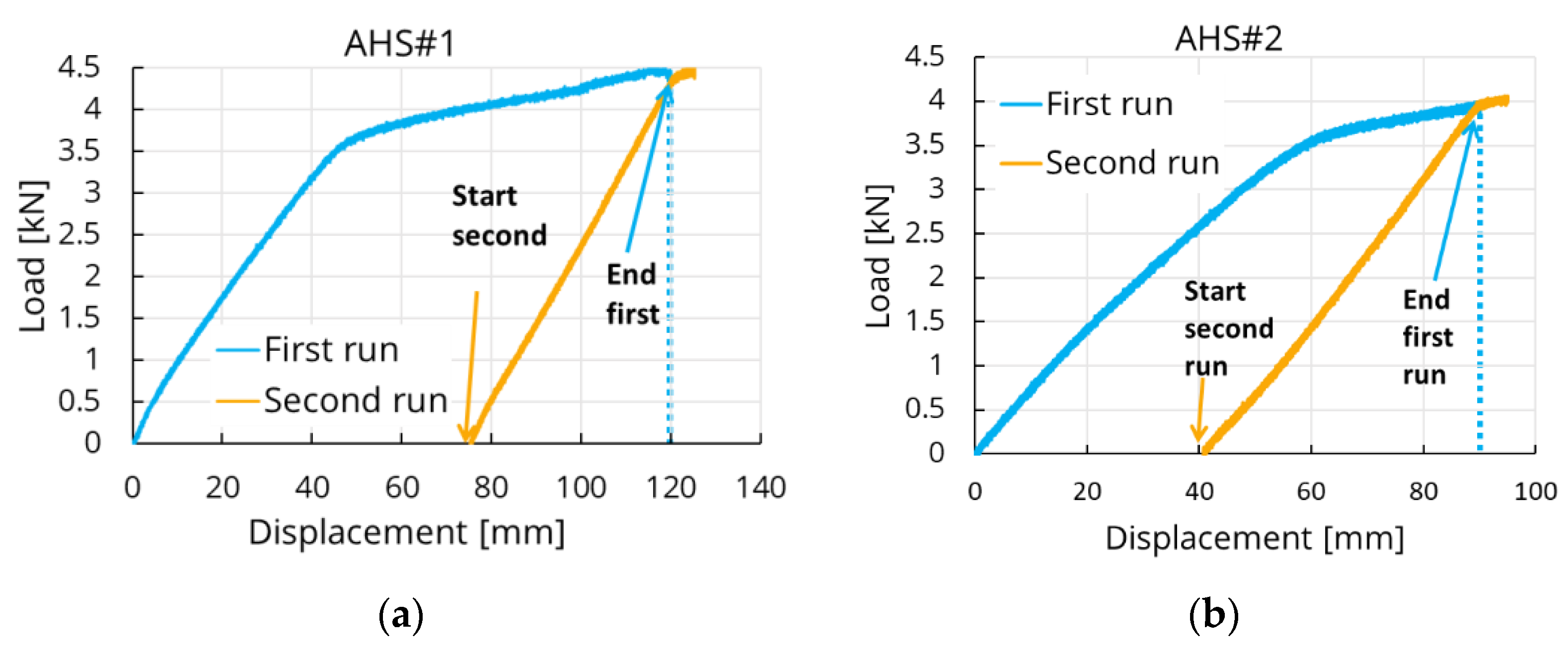
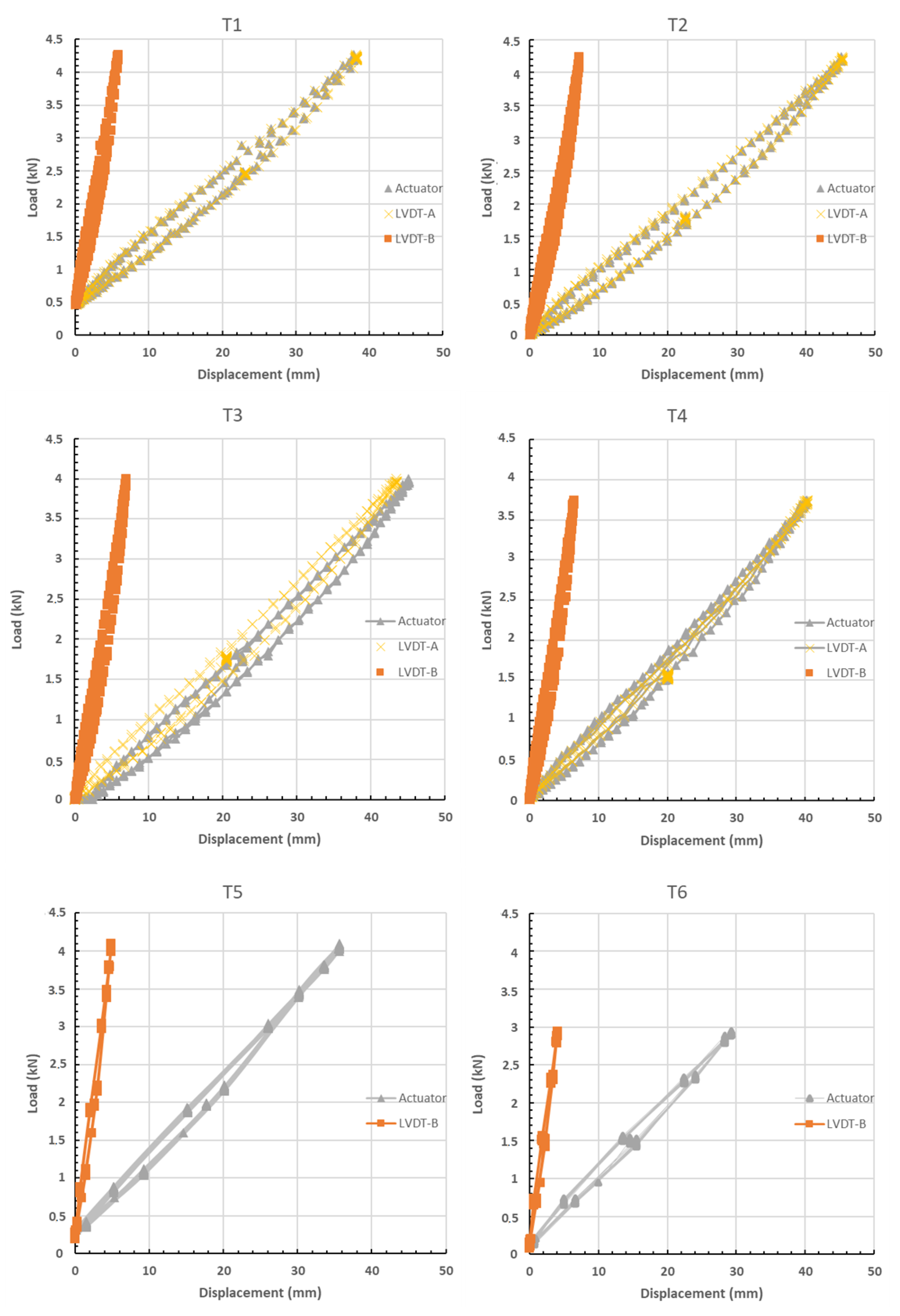
Quasi-static analysis was repeated twice for each panel. After the first loading run, the panels were unloaded, enabling the elastic recover of the structure, and then the load was applied on the same panel for a second testing run.
The results of loading sequence for both structures are reported in
Figure 8, which shows a typical strain hardening response for both panels.
As predictable, AHS#1 produced a stiffer response than AHS#2, as a consequence of the smaller honeycomb cell size. LVDT-A and the actuator displacement sensor yielded almost the same measurement for both panels, confirming that no cell crushing occurs in the region of load application. Both structures experienced plastic deformation, which resulted in the panel’s bending under the applied load without producing any relevant sign of failure in the core and skins. No criticalities were detected in the bimetallic joints, confirming the reliability of such solution, which could play a crucial role in enhancing a broader use of structural parts made of lightweight alloys.
Even though the tested AHS panels have different stiffness, the maximum load reached during both tests was relevant: this endorses the integration of similar lightweight solutions in prefabricated balcony modules and in other structural components for shipbuilding.
According to DNV GL rules for passenger ships [
34], prefabricated balcony modules must be tested with a test load of 0.25 t/m
2. In order for the structure to pass the test, no visual damage or permanent deflections must be observed upon removal of the test load. For the described analysis, a concentrated load instead of a distributed one was used. However, in order to provide a comparison with the requirements of the rules, the following evaluation was performed:
It was supposed that the reference load of 0.25 t/m2 was applied on the tested structure;
The maximum bending moment at the fixed end produced by such load was calculated, and it was found equal to 527.3 N mm;
The equivalent concentrated load at the free end of the balcony, which produces the same bending moment of the reference load was calculated, and it was found equal to 0.48 kN.
From the experimental analysis, it was observed that the tested structure with both AHS panels, is able to withstand more than 3 kN before showing any sign of plastic deformation. This further confirms the potentialities achievable by introducing similar lightweight concept in marine structures.
The full-scale quasi-static testing allowed the evaluation of the whole structure response, which is essential information to support the design and guarantee the reliability of complex structures, where the interaction among several components is not easily predictable. In addition, the data obtained from quasi-static analysis were fundamental to arrange fatigue tests.
4.2. Fatigue Tests
Preliminary fatigue tests, at variable amplitude displacements, were performed in order to investigate the cyclic hardening and the load–displacement hysteresis. Fatigue tests were performed at a frequency equal to 1 Hz. The collapse modes of the failed honeycomb panel after fatigue tests were investigated using X-ray radiography.
Table 4 reports the test sequence during the preliminary test. Since it was expected that the structure would suffer from plastic deformation, a loading sequence with growing displacement ratios was applied, with the aim of reaching a stable condition in which the actuator also keeps the contact with the panel at the minimum applied displacement, which means that it also applies a non-zero force at the minimum applied displacement. For this reason, the position of contact (non-zero force) is reported in
Table 4 at the end of the test sequence and after N number of cycles. The table also reports the displacement ratio (
Rd) calculated as
and the applied displacement range (Δ
d).
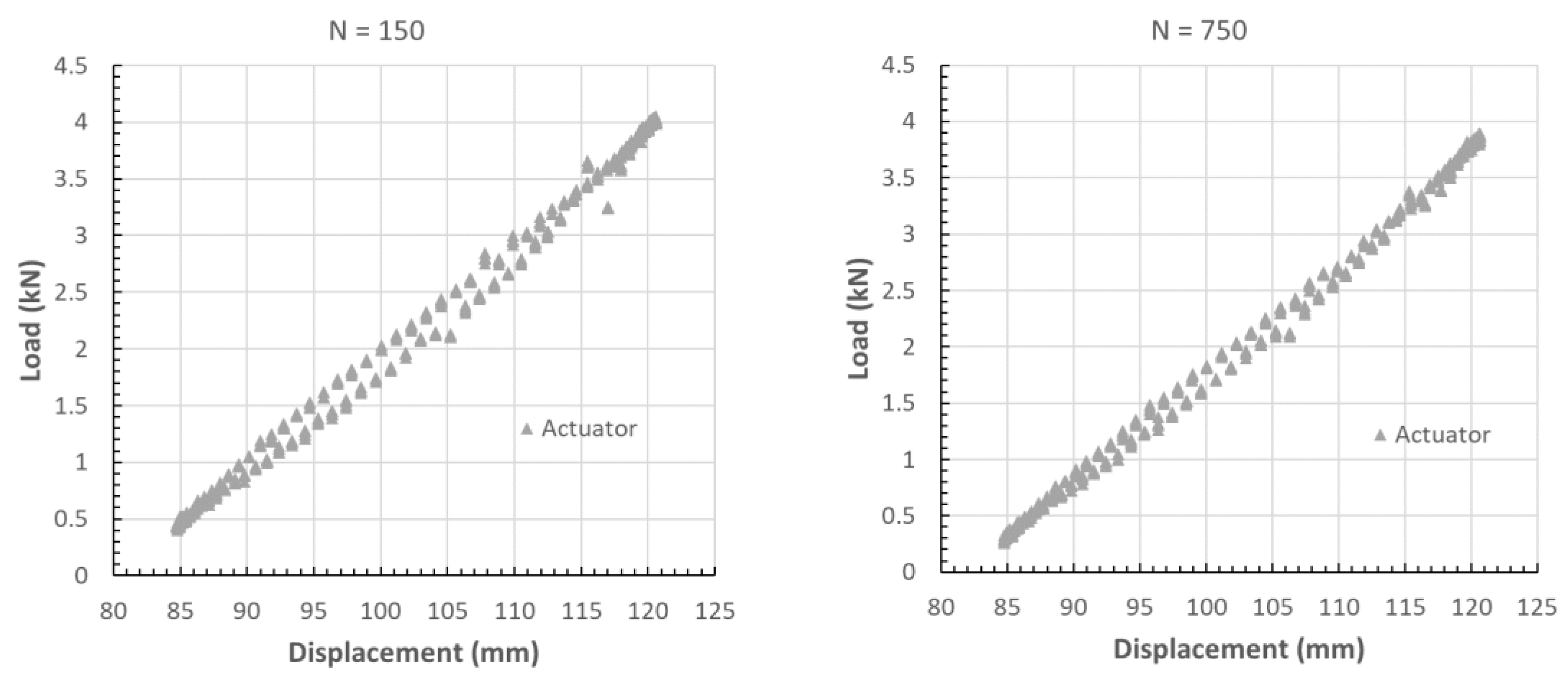
The table clearly shows that a significant hardening of the structure is observed. Indeed, an increase in the non-zero contact force position equal to 63 mm was suddenly observed after just five cycles.
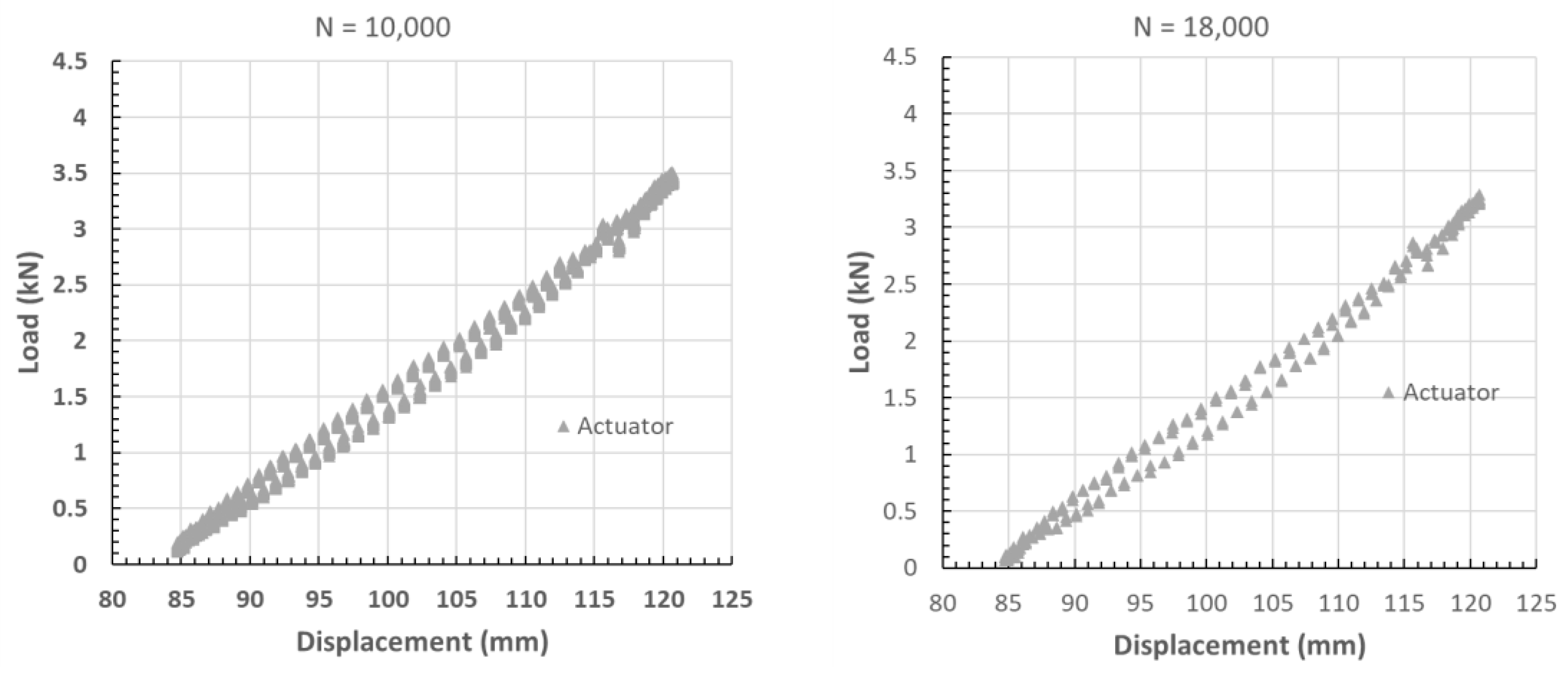
Figure 9 shows the recorded hysteresis cycles during each test sequence, using the same scale.
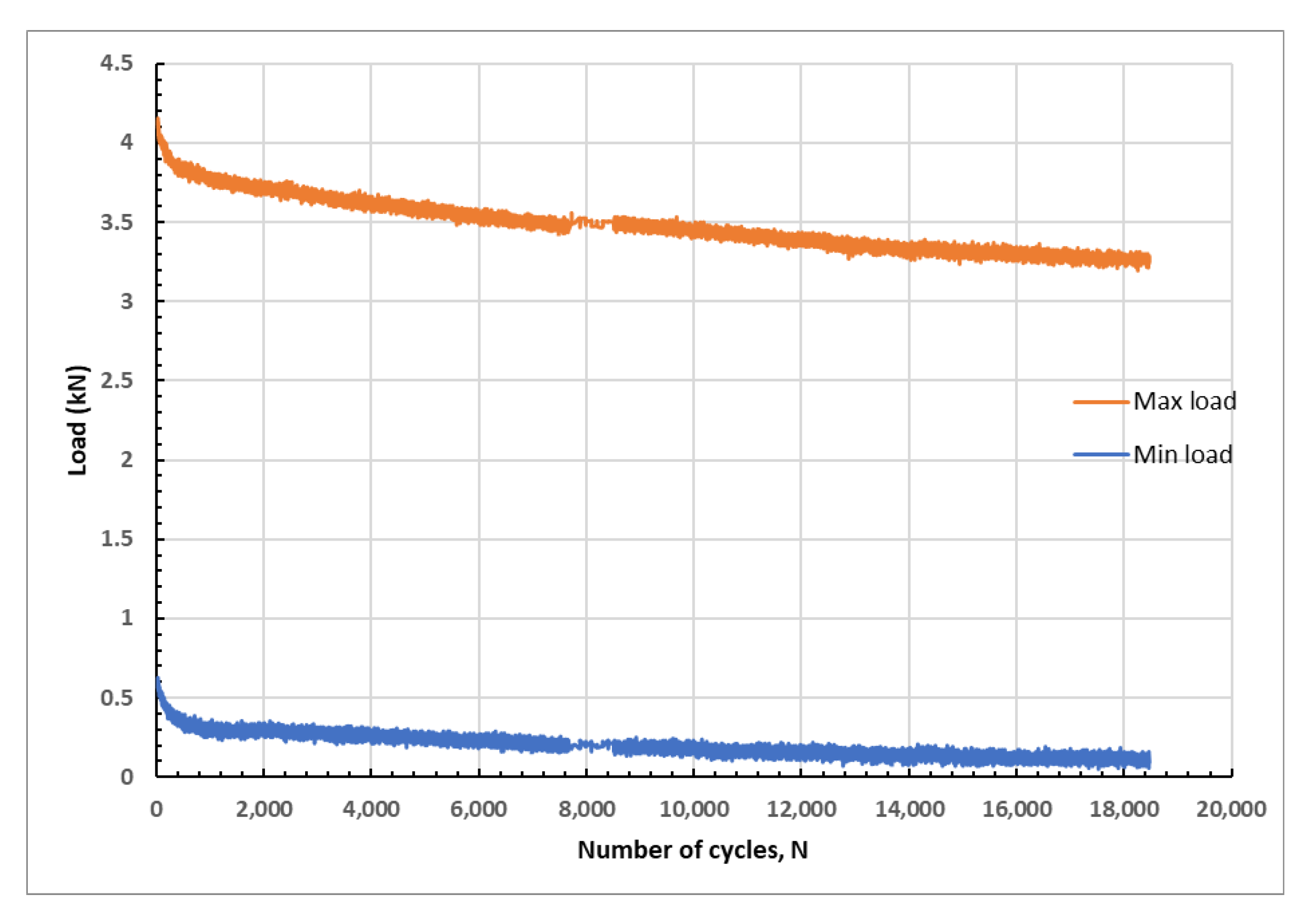
A further fatigue test using a constant displacement range was performed considering the condition of test sequence 5 of
Table 4.
Figure 10 shows the maximum and minimum load recorded during the test. The maximum and minimum load at the beginning of the test were equal to 4.2 kN and 0.62 kN, respectively. The test was stopped when a 30% decrease in the maximum load was observed [
35], which was used as a failure criterion as cracks had already developed.
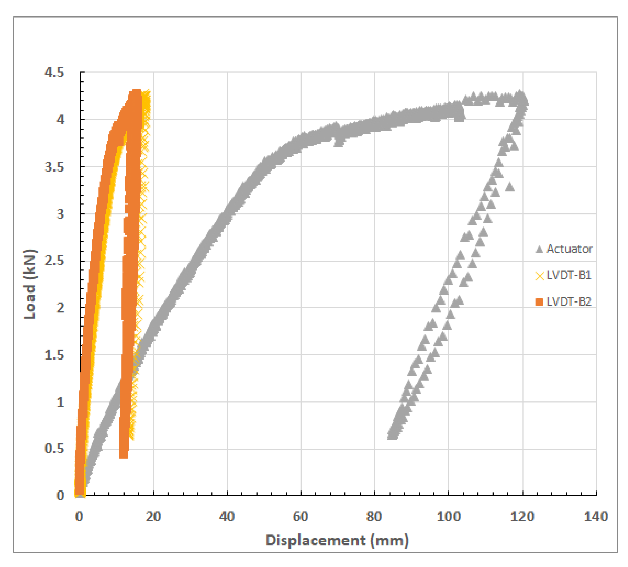
Figure 11 shows the load–displacement curves at the initial stages of the tests. LVDT-B1 and LVDT-B2 have the same displacements, and thus, no torque stresses were observed. The same figure shows the hardening of the balcony.
Figure 12 displays the hysteresis curves registered during the test at different cycles, confirming the load decrease. The figure shows that the hysteresis loop is constantly decreasing during the test.
It is worth underlining that the bimetallic junction has no cracks, and it can be affirmed that it can be used to connect ship balcony overhang made of aluminium, thus saving a considerable amount of weight.
4.3. Collapse Modes
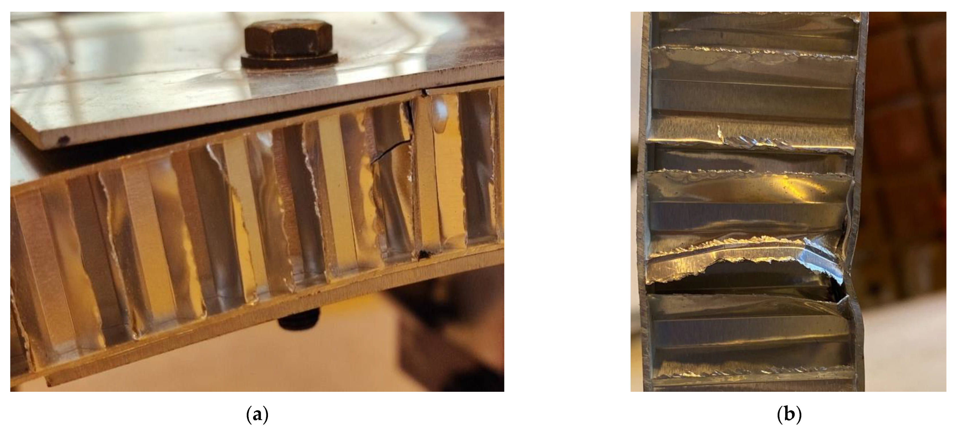
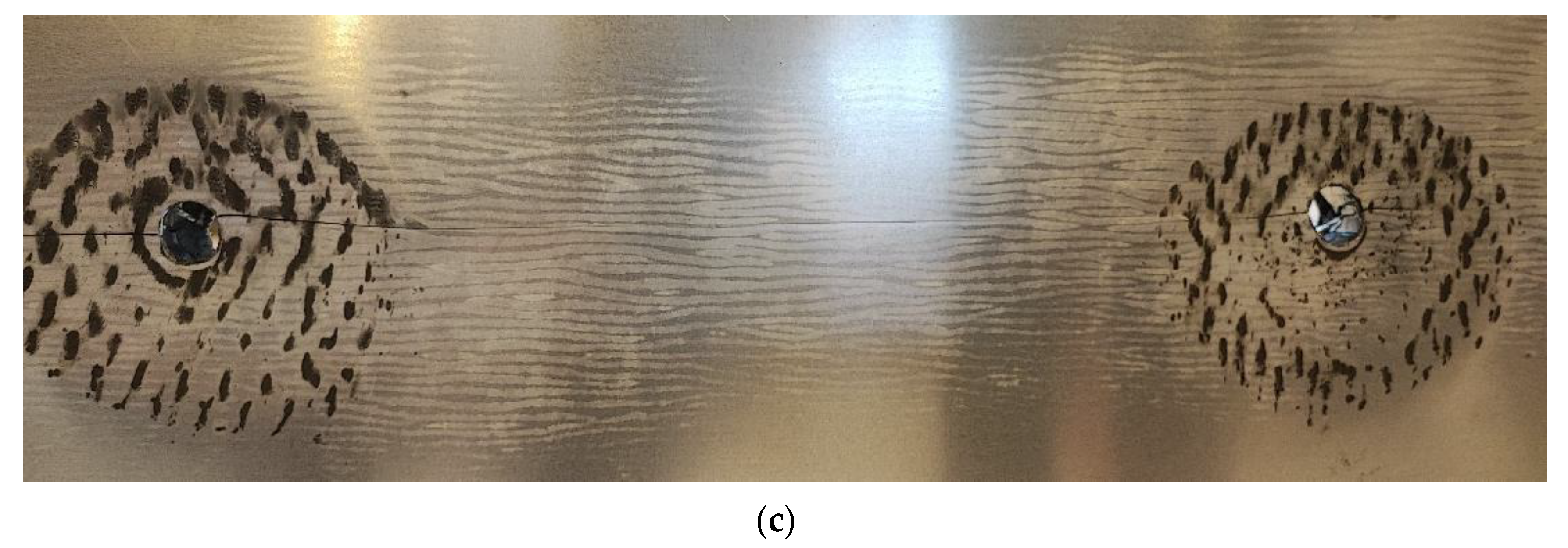
Pictures of the failed honeycomb panel after the fatigue tests at variable amplitude displacements are displayed in
Figure 13. The results show that multiple sites and modes of failure are present. All of them are at the same longitudinal position of the bolted joints. The first failure site is situated on the right-hand side of the panel (
Figure 13a) and consists of a shear crack on one of the later cell walls. The second failure site is located on the opposite side and a collapsed cell is observed (
Figure 13b). In addition, as shown by
Figure 13c, a crack between two bolts is observed.
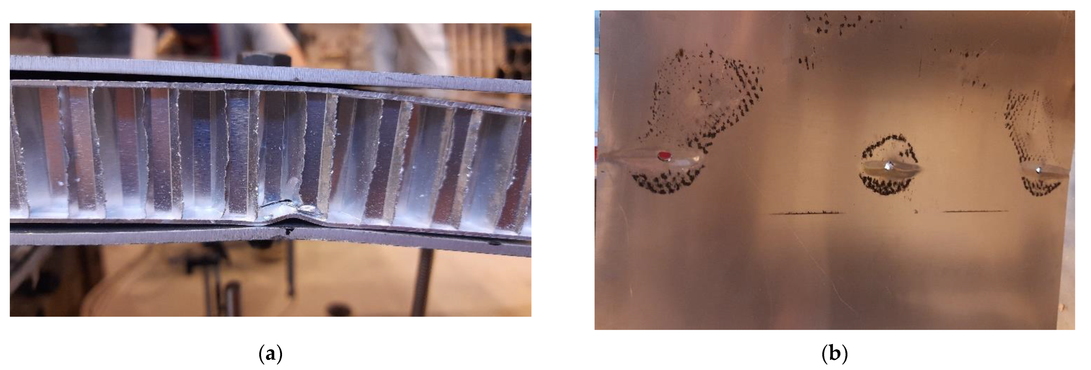
The failure modes observed after the second fatigue tests are similar to those already described for the first fatigue test. Some details are displayed in
Figure 14.
As visible in
Figure 14a, similarly to the first fatigue test, a local shear crack across one of the lateral cell walls was detected, nearby the bolted connection. At the same location, skin wrinkling was visible during the test. Local skin wrinkling occurred in the surrounding area of all bolted joints, on the compressed face of the panel, as shown in
Figure 14b.
In order to perform an in-depth and non-destructive investigation of the collapse mechanisms, the panel from to the first fatigue test was subjected to radiographic inspection with a Bosello System SRE m@x equipment. The X-ray tube was set at a voltage of 58 kV and at a current of 0.6 mA. The focal spot size was set to 0.4 mm, and the radiographies were post-processed by applying a median EN filter.
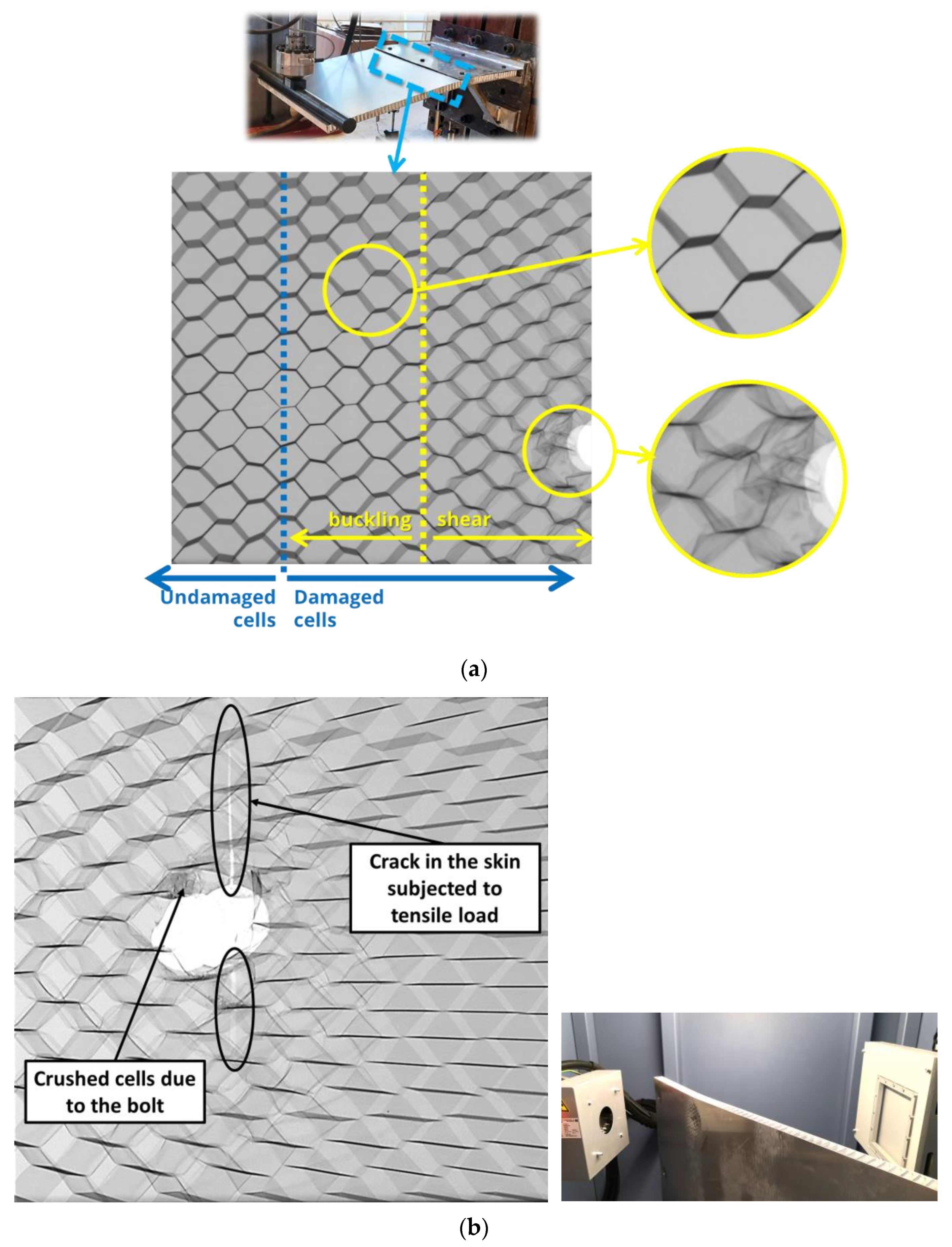
The region of interest for the radiographic analysis was the area of the AHS panel included between the supporting plates. X-ray images obtained from the inspection are displayed in
Figure 15.
As visible in
Figure 15a, which refers to the region close to the first raw of holes, it is possible to distinguish between a region where cell walls are not damaged and a region where permanent damage is detectable. The former refers to the AHS portion far from the part which is between the supporting plates; the latter is the region nearby the bolted connection. The damaged area can be further distinguished into a zone where cell walls buckling is mainly visible and a region where the load was more severe and cell walls failed after shear.
Figure 15b reports another detail of a hole belonging to the first row, where, in addition to crushed cells, the crack crossing the top skin is clearly visible, already displayed in
Figure 13c.
All the bimetallic welded joints, subjected to visual inspection, showed no sign of failure initiation. Since they are significantly stiffer than the panel and the supporting plates, no relevant deformation or other alterations were expected. In addition, their presence allows the supporting plates to be fully fixed to the main wall, hence obtaining a safe and steady connection where it is expected.
5. Conclusions
Full-scale bending tests were performed on a ship balcony overhang, including an aluminium honeycomb sandwich panel and bimetallic joints, with the intention of assessing alternative lightweight solutions in shipbuilding. The proposed solutions were investigated by means of static and fatigue tests. The same supporting frame was employed to test AHS panels with two different cell size. The AHS panels experienced plastic bending deformation, after an applied load greater than 3.5 kN, keeping the integrity of both core and skins. Under quasi-static conditions, the panel with the smaller cell size yielded a stiffer response, which is more desirable for overhang ship parts, without significantly increasing the mass (0.8 kg of difference). However, both alternatives were capable of withstanding demanding loading conditions, suggesting that similar solutions have the potentialities to be employed in shipbuilding. The suggested solution, which includes the use of bimetallic joints, allowed the application of aluminium supporting plates and brackets, which have the potential to further reduce the weight of similar structures, compared to traditional solutions entirely made of steel.
The fatigue tests allowed the assessment of the hysteresis cycles and the load decrease. Both preliminary fatigue tests, at variable amplitude displacements and a fatigue test using a constant displacement range, were performed. At the beginning of the constant displacement tests, the registered values of the maximum and minimum load were equal to 4.2 kN and 0.62 kN, respectively. The test was stopped when almost a 30% decrease in the maximum load was observed, since it was found that a crack had already propagated.
The results of the X-ray analyses showed that multiple sites and modes of failure are present. The damaged area of the honeycomb panel was distinguished into a zone where cell walls buckling is mainly visible and a region where the load was more severe, and cell walls failed after shear.
The presence of the bolts influences both static and fatigue strength of the overhang ship balcony structure. The bimetallic junction has experienced no cracks and it can be affirmed that it can be used to connect the ship balcony overhang made of aluminium to the steel ship structure, allowing the saving of a considerable amount of weight. The systematic analysis of the experimental results gave valuable data to enhance the design methodology of such structures.

 ,
, 


