

Fluid-Structure Interaction Analyses for Hydro-Elastic Tailoring of a Windsurfer Fin
 ,
,
Abstract
:1. Introduction
2. Numerical Model
2.1. Structural Analysis
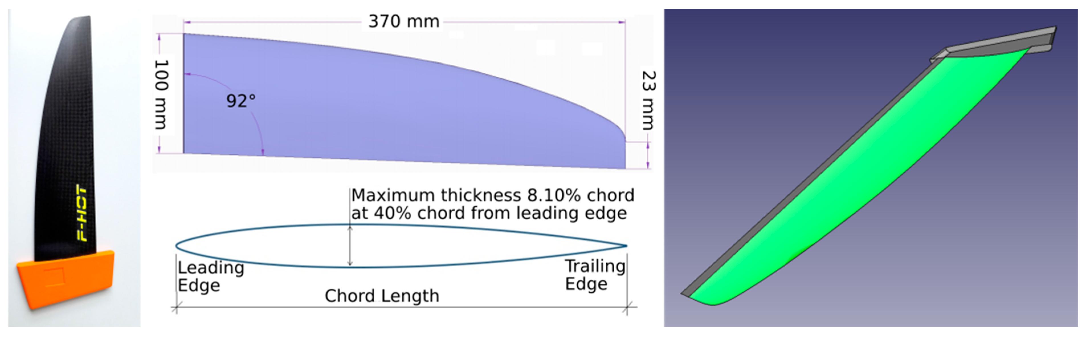
2.1.1. Geometry and Lay-Up
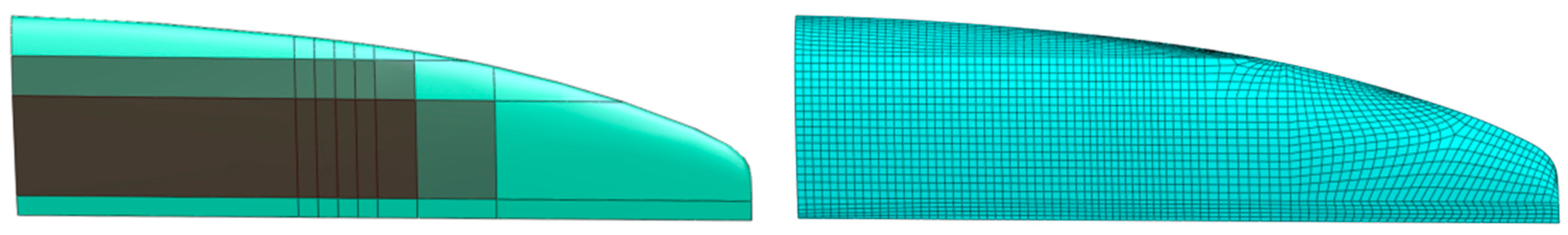
2.1.2. Elements, Mesh and Boundary Conditions
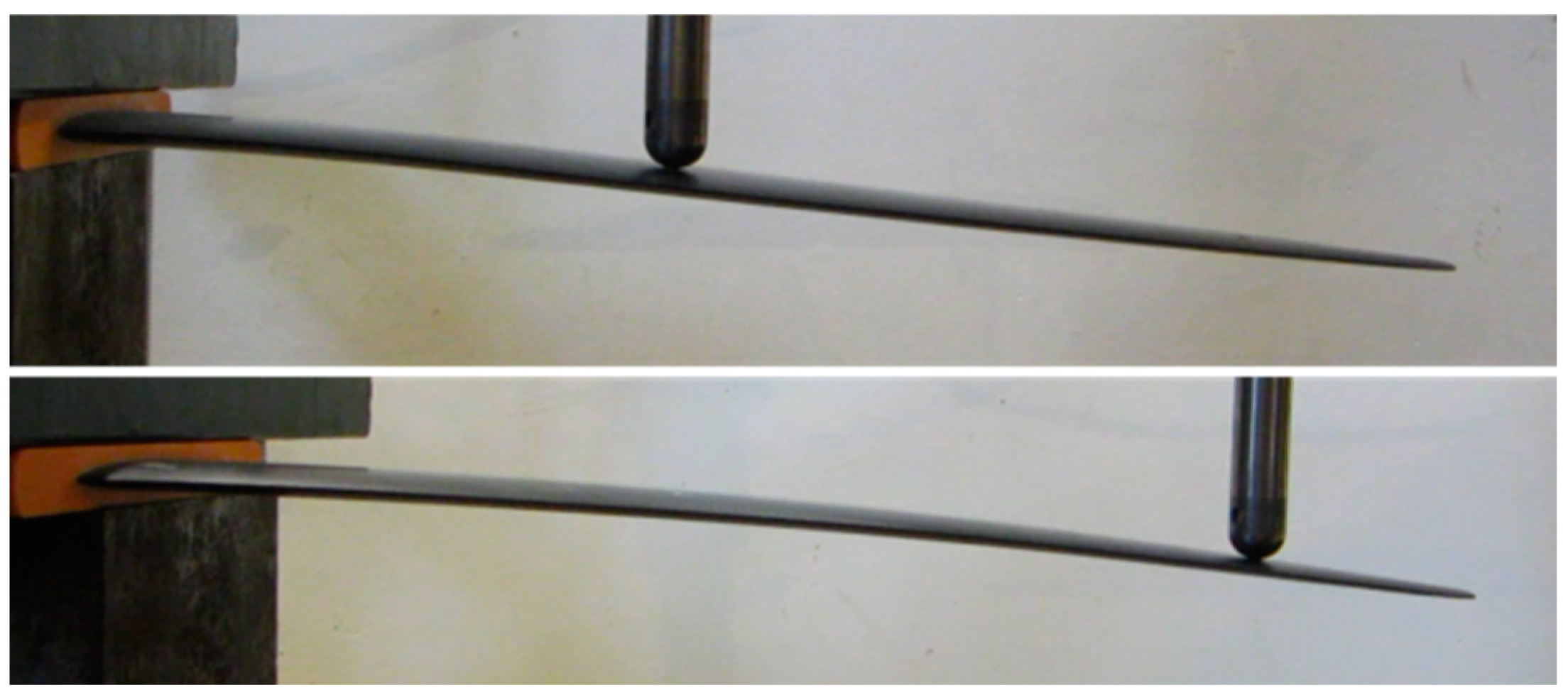
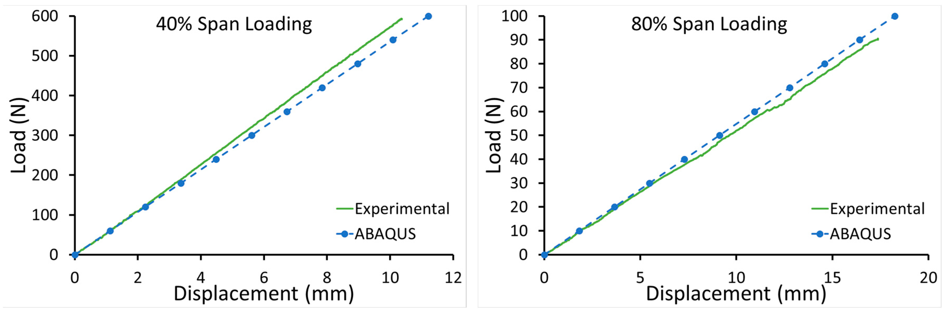
2.1.3. Material Properties and Structural Model Verification
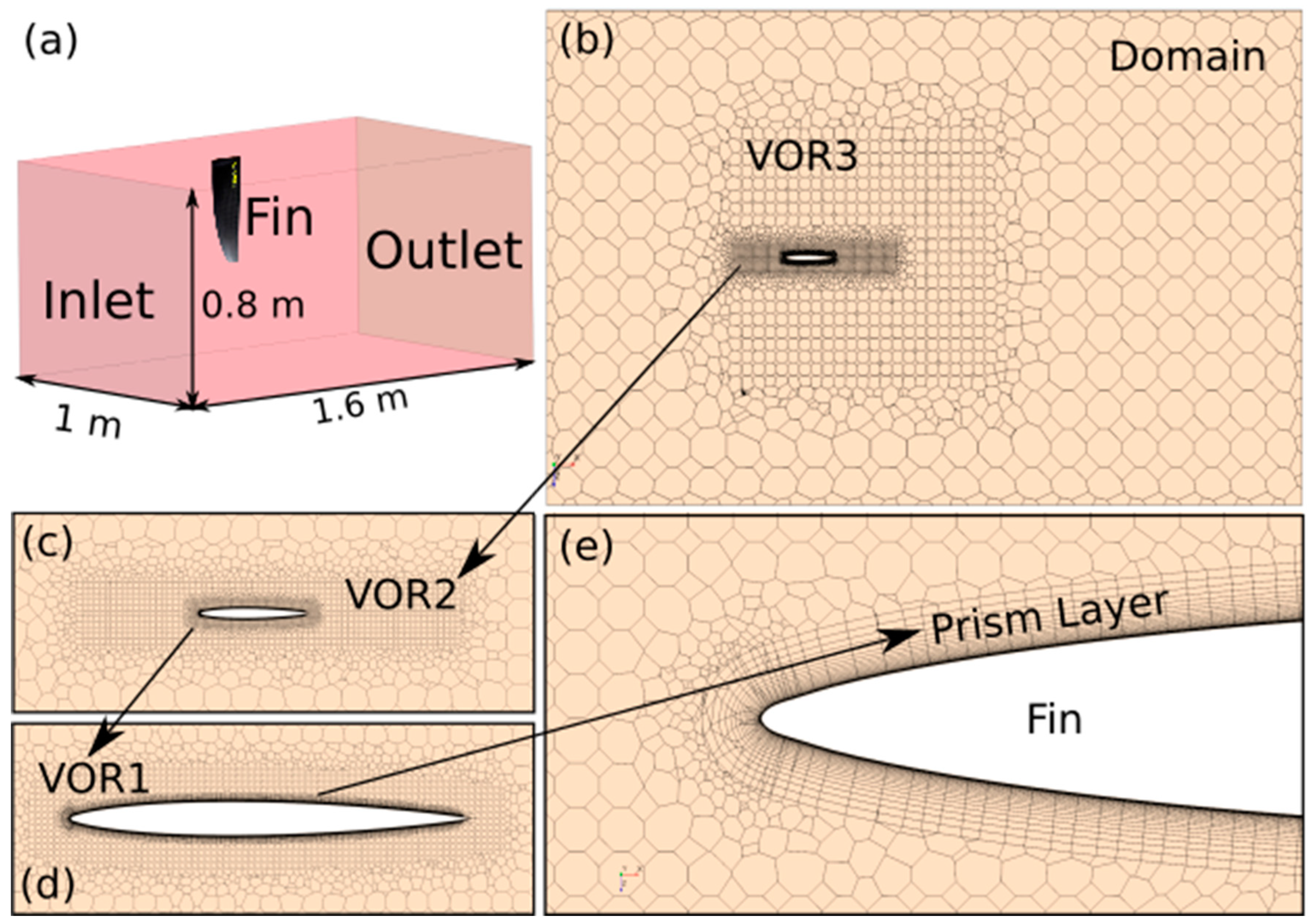
2.2. Computational Fluid Dynamics Analysis
- Three-dimensional analysis
- Steady and segregated flow
- Constant density
- Turbulent flow solving the Reynolds-averaged Navier–Stokes equations
- K-ω, SST (menter) turbulence model
- γ−Reθ transition model
- Low y+ wall treatment
2.3. FSI Analysis
3. Parametric Study
3.1. Results
3.2. Discussion
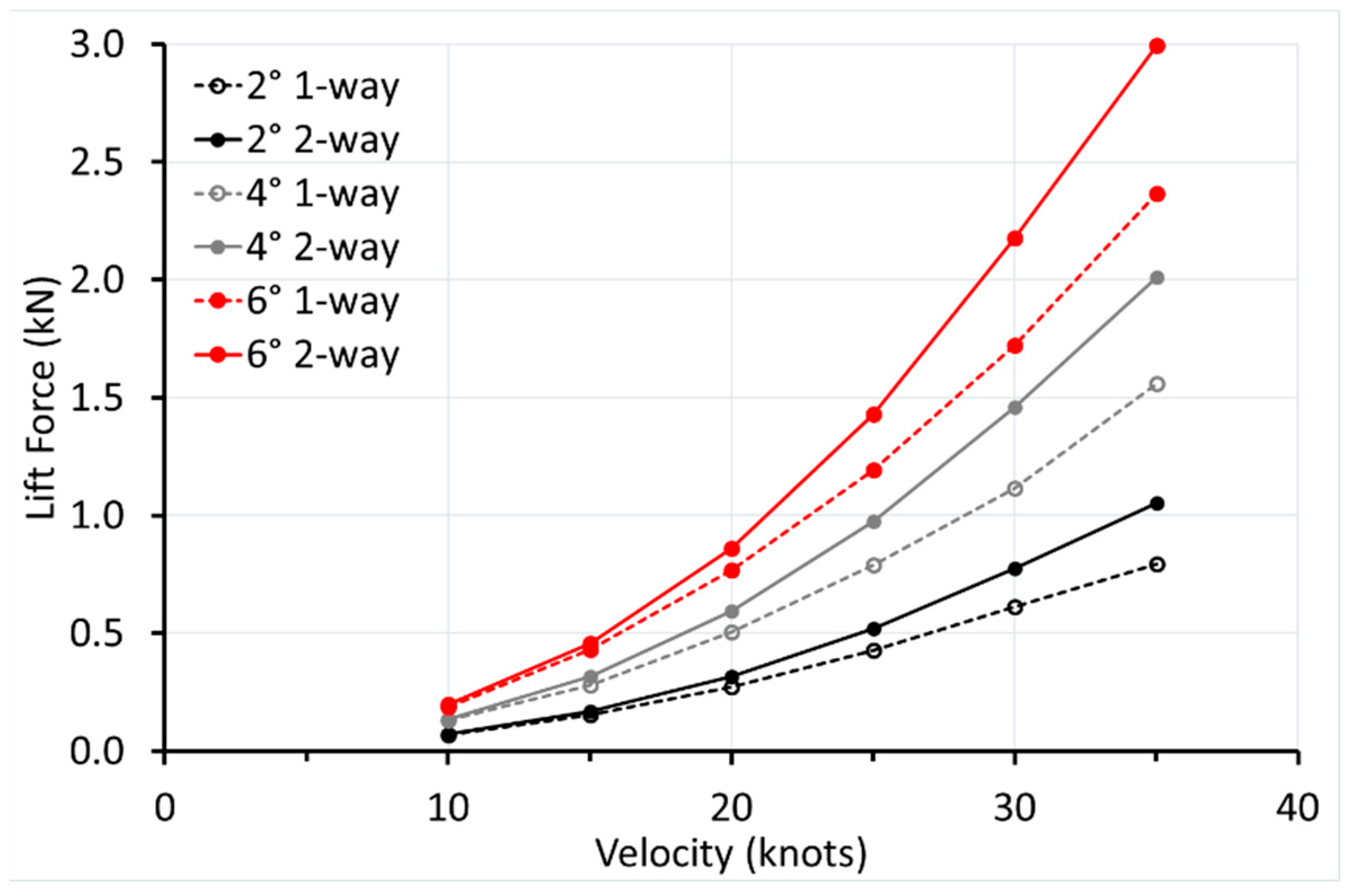
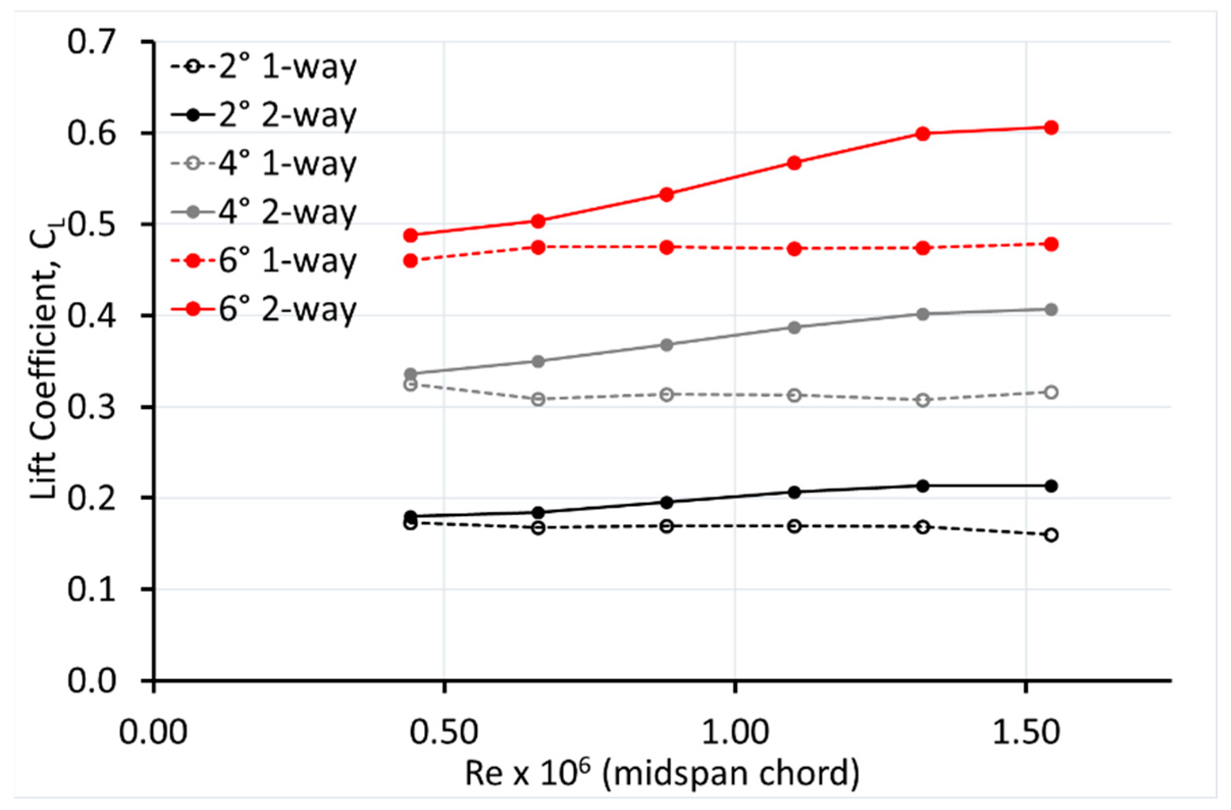
3.2.1. Lift
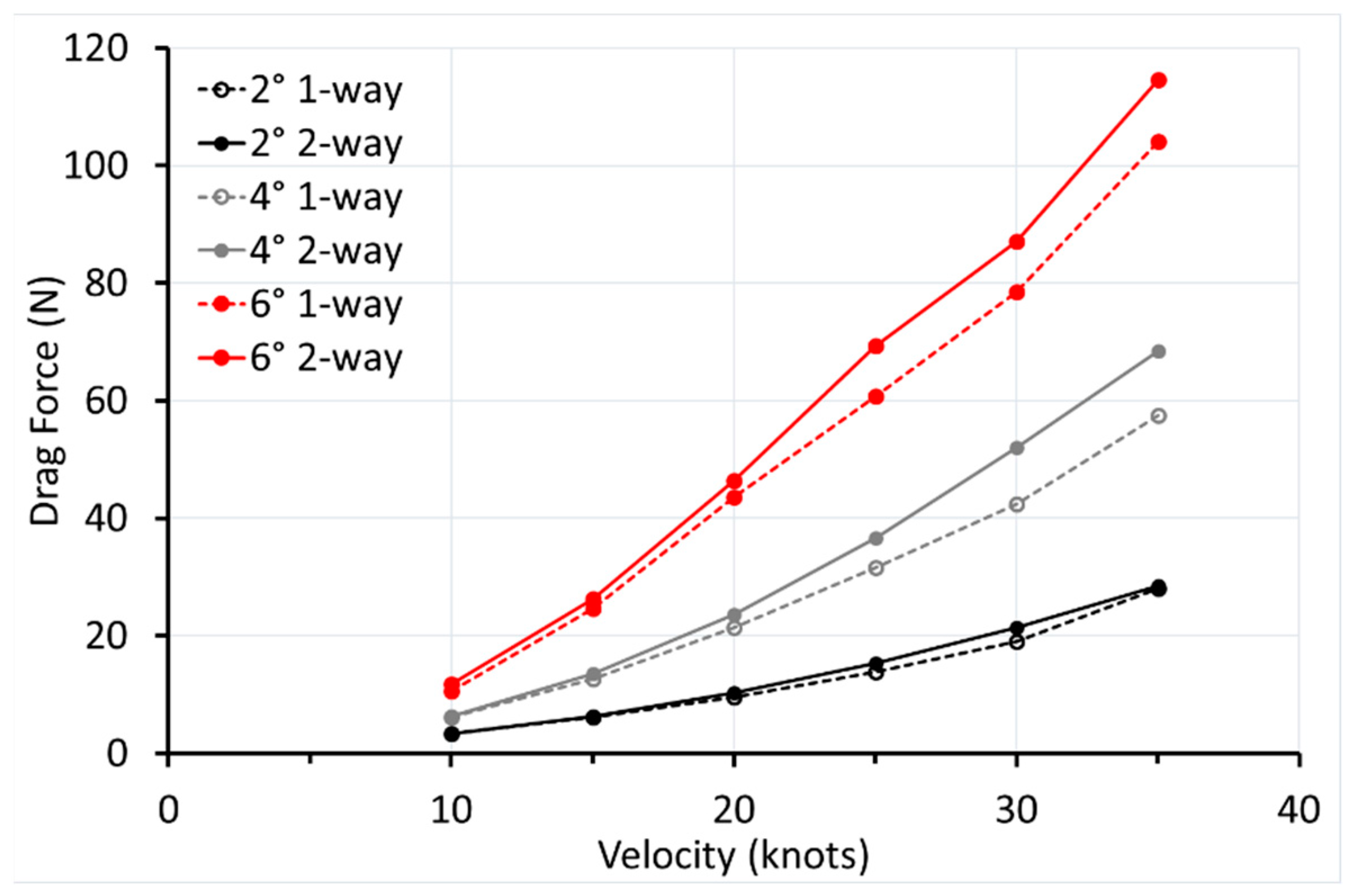
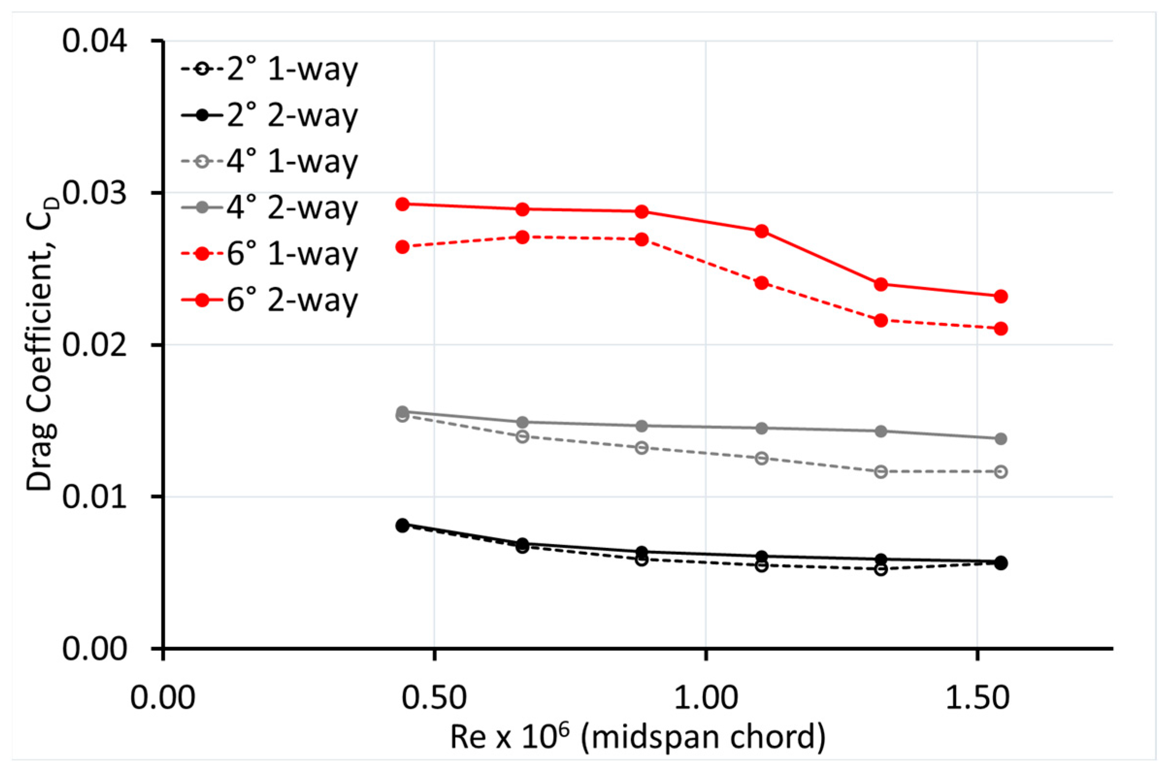
3.2.2. Drag
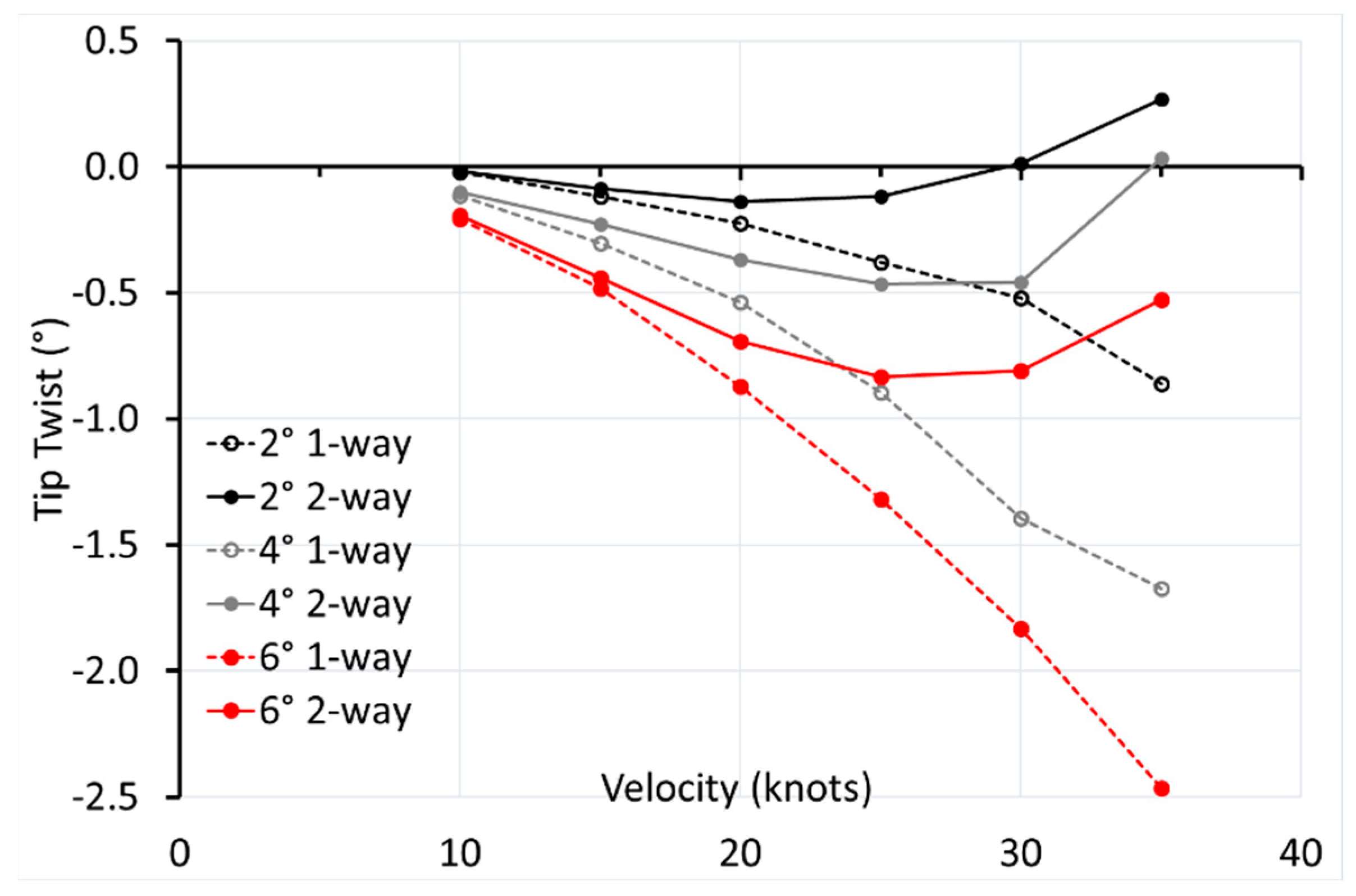
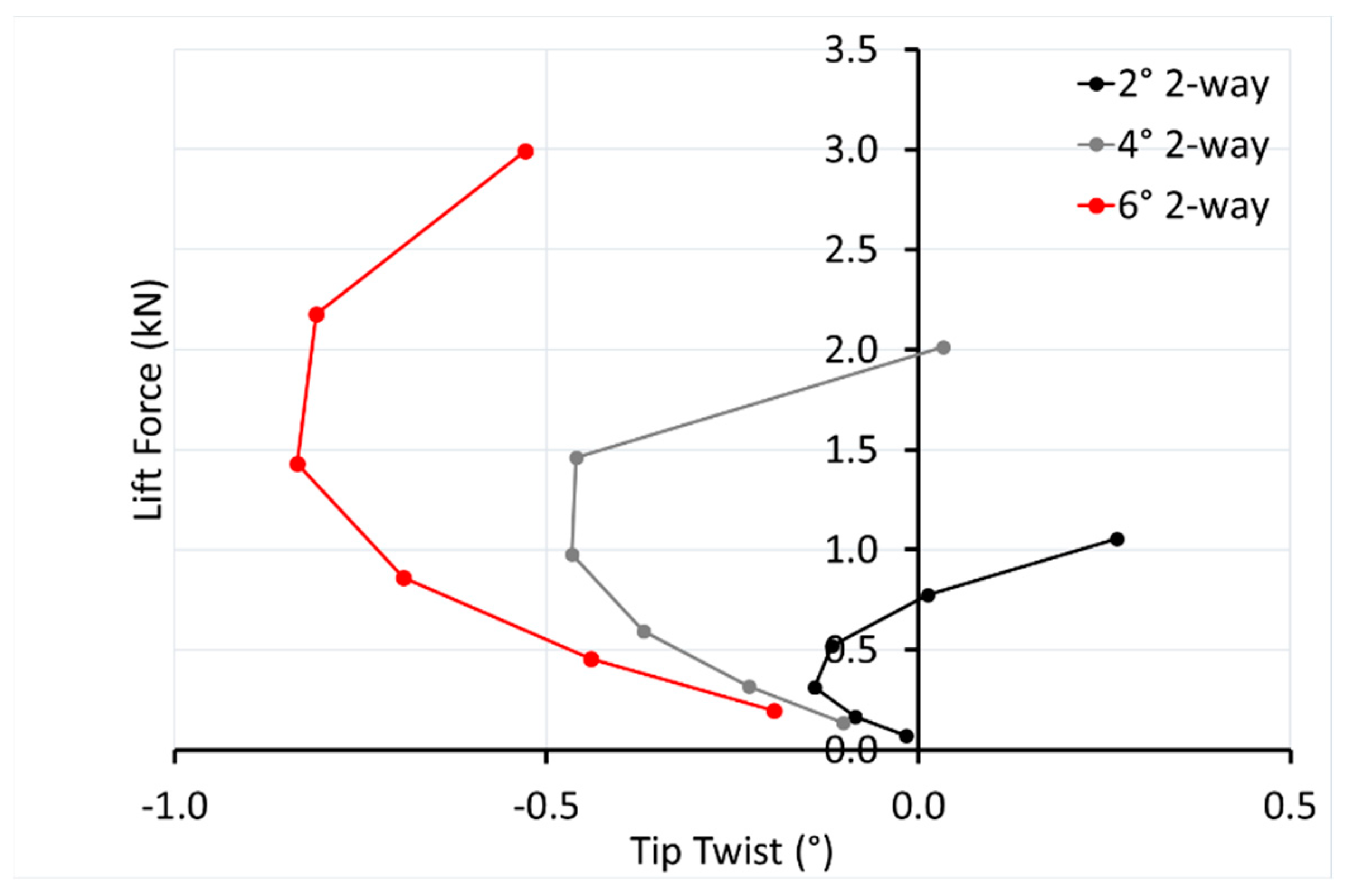
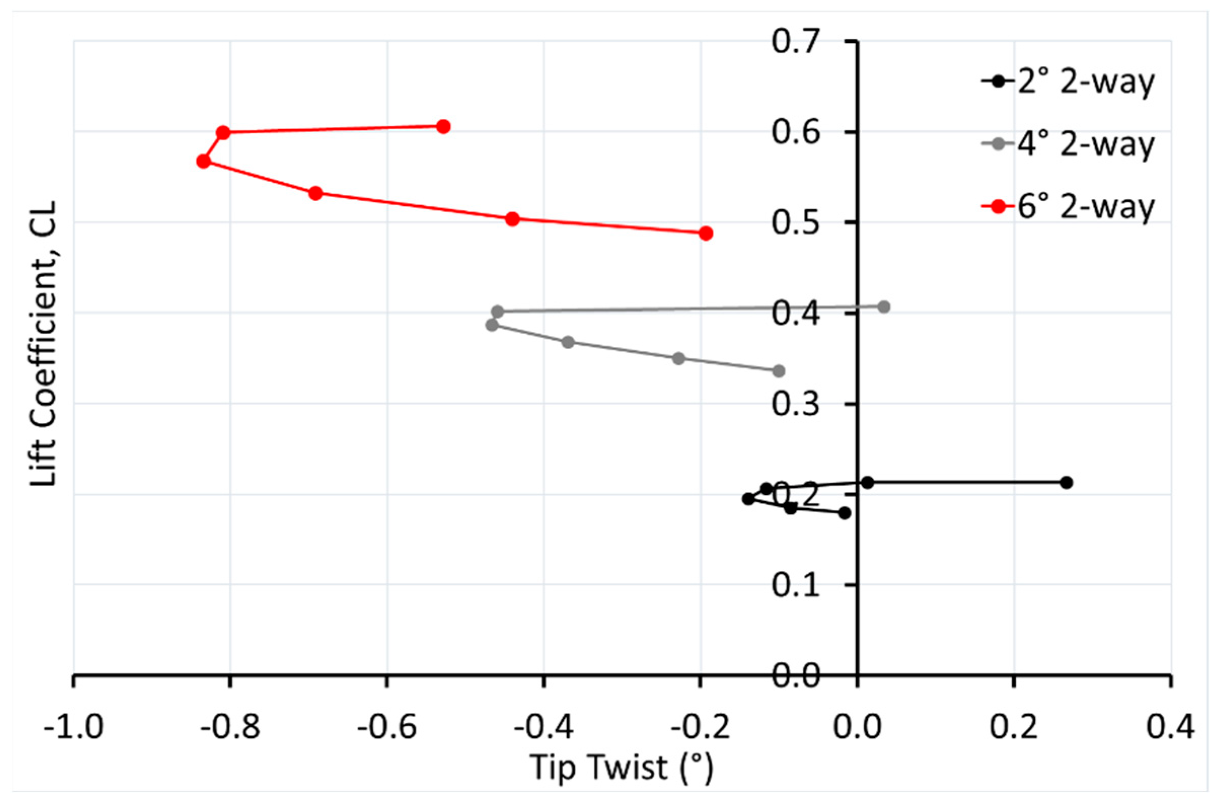
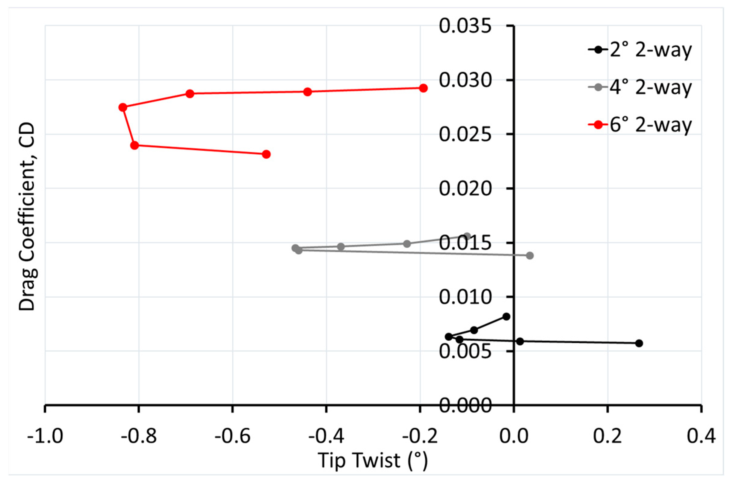
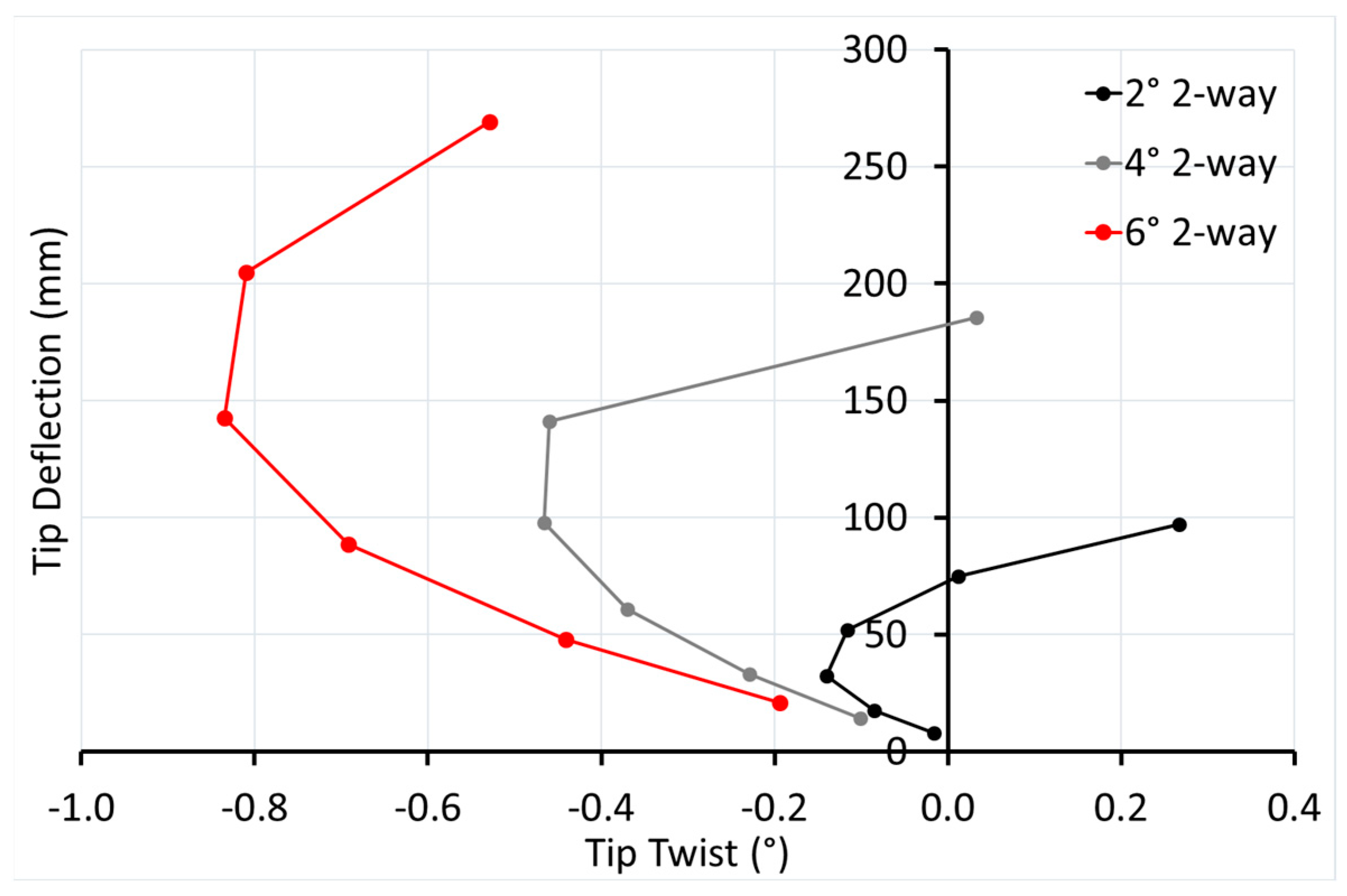
3.2.3. Tip Twist
- Structural bend-twist coupling due to planform sweep and/or laminate layup (see Section 4)
- (i)
- The main UD carbon stiffening plies are shown as darker shaded areas in Figure 2, indicating that the structural shear centre is significantly aft of the ¼-chord line of the fin for the majority of its span. Since the fin foil section is symmetrical, the centre of pressure will be fairly close to the ¼ chord (for most of the span), leading to an overall hydrodynamic wash-in (negative twist, AoA increase) moment. However, at the tip, finite wing effects may produce a local hydrodynamic wash-out (positive twist, AoA decrease) moment [36].
- (ii)
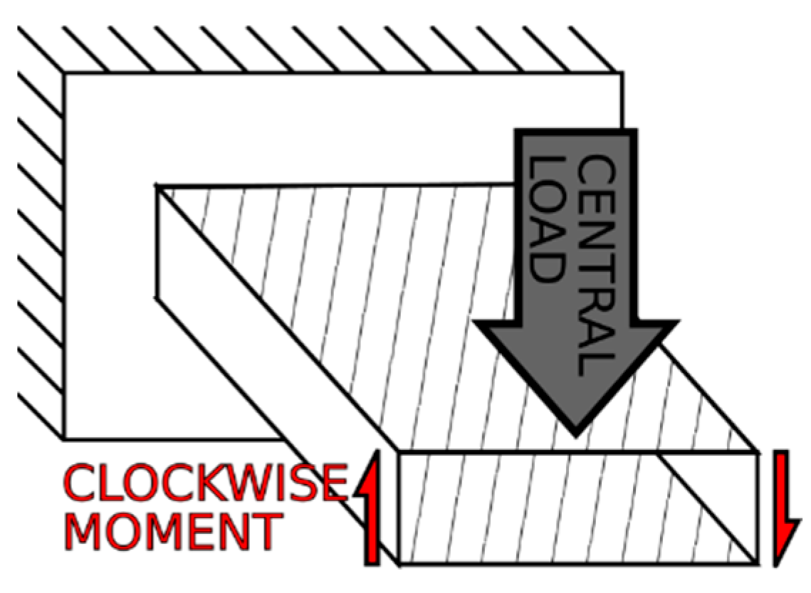
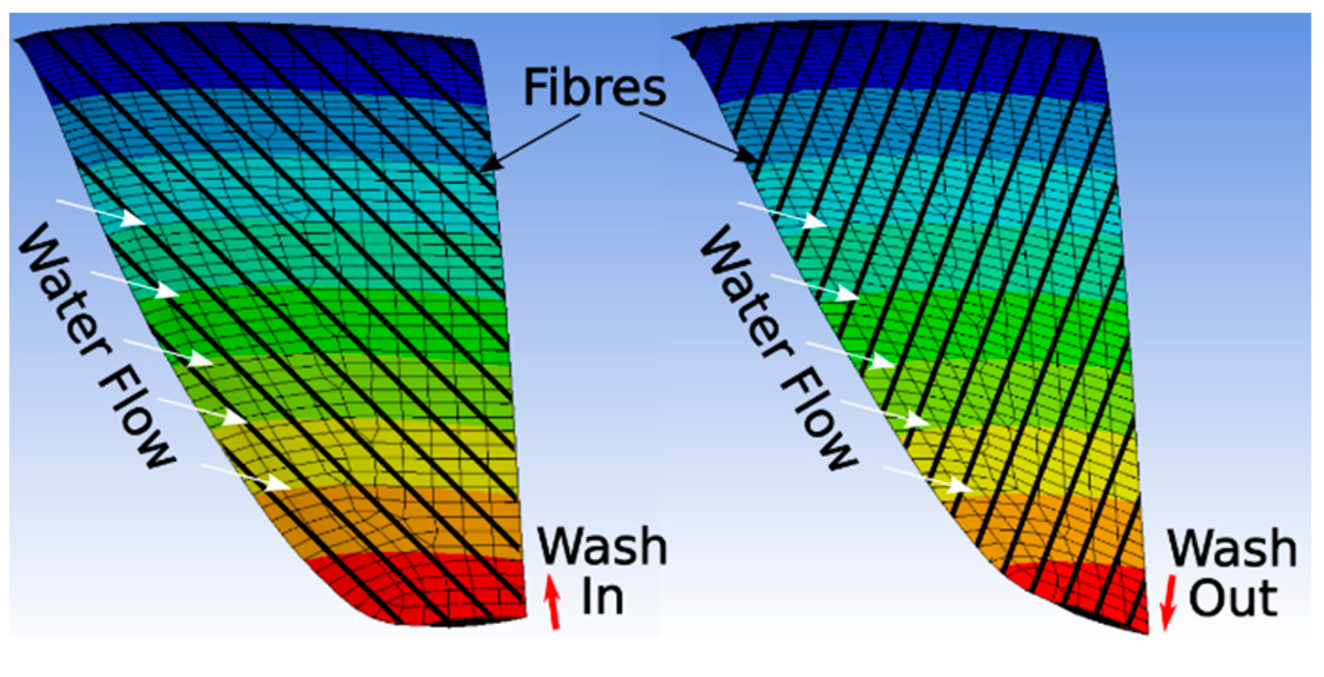
- The aft-swept fin planform (due to the aft-swept leading edge) produces a wash-out (positive twist, AoA decrease) bend-twist coupling effect [3,34]. The symmetric, balanced layup of nominally 0° UD and ±45° biaxial reinforcements theoretically gives no bend-twist coupling. However, since the plies are laid up with respect to the trailing edge, the plies are angled slightly forward with respect to the ¼ chord line and hence some degree of laminate induced wash-out (positive twist, AoA decrease) bend-twist coupling is also possible.
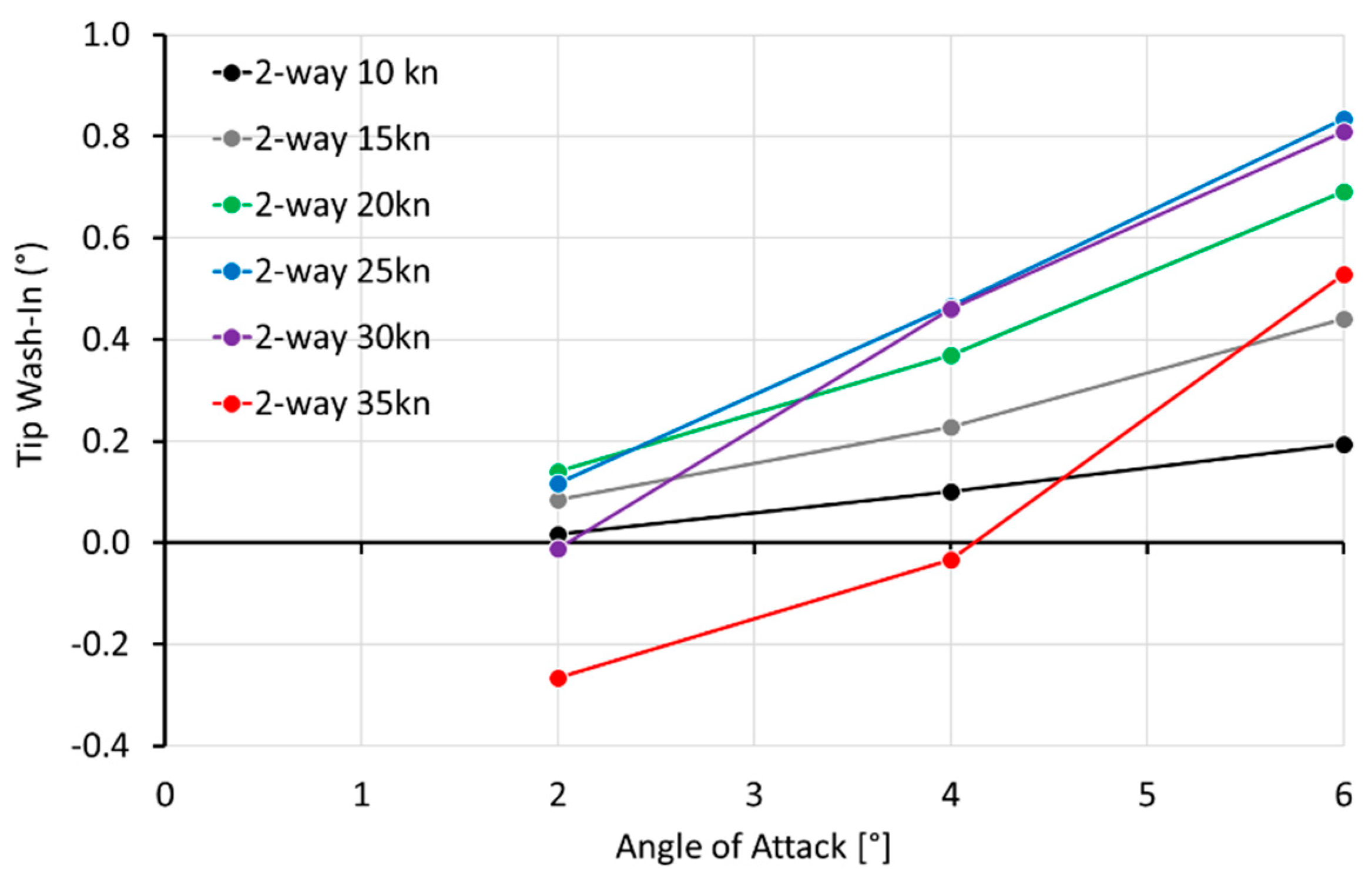
- Hydrodynamic wash-in effects appear to be dominant, except at high velocity and lower AoA combinations (Figure 8).
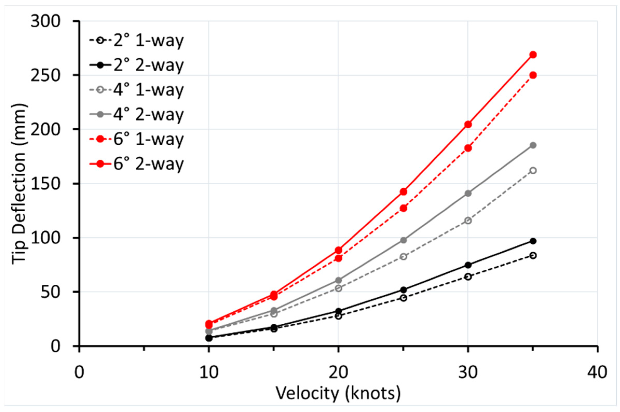
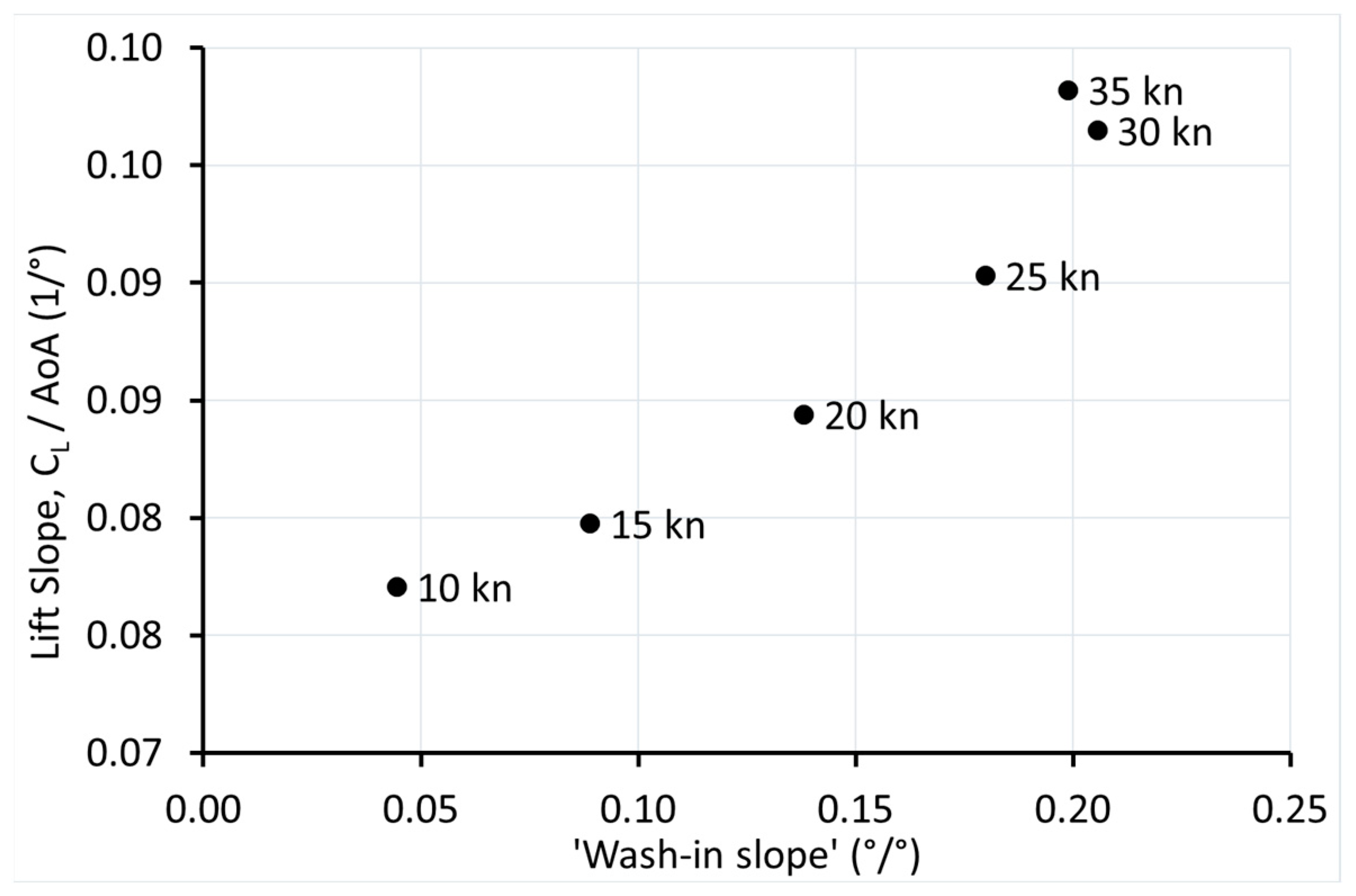
- Since one-way and two-way tip deflections are similar (Figure 9), it can be deduced that the decrease in wash-in at higher velocities seen for the two-way analysis, but not for the one-way analysis, is not due to structural bend-twist coupling, and thus hydrodynamic wash-out moment effects appear to be responsible.
- The hydrodynamic loading from the rigid fin shape deforms the fin in such a way that the hydrodynamic tip torsional loadings are reduced (Figure 19).
3.2.4. Tip Deflection
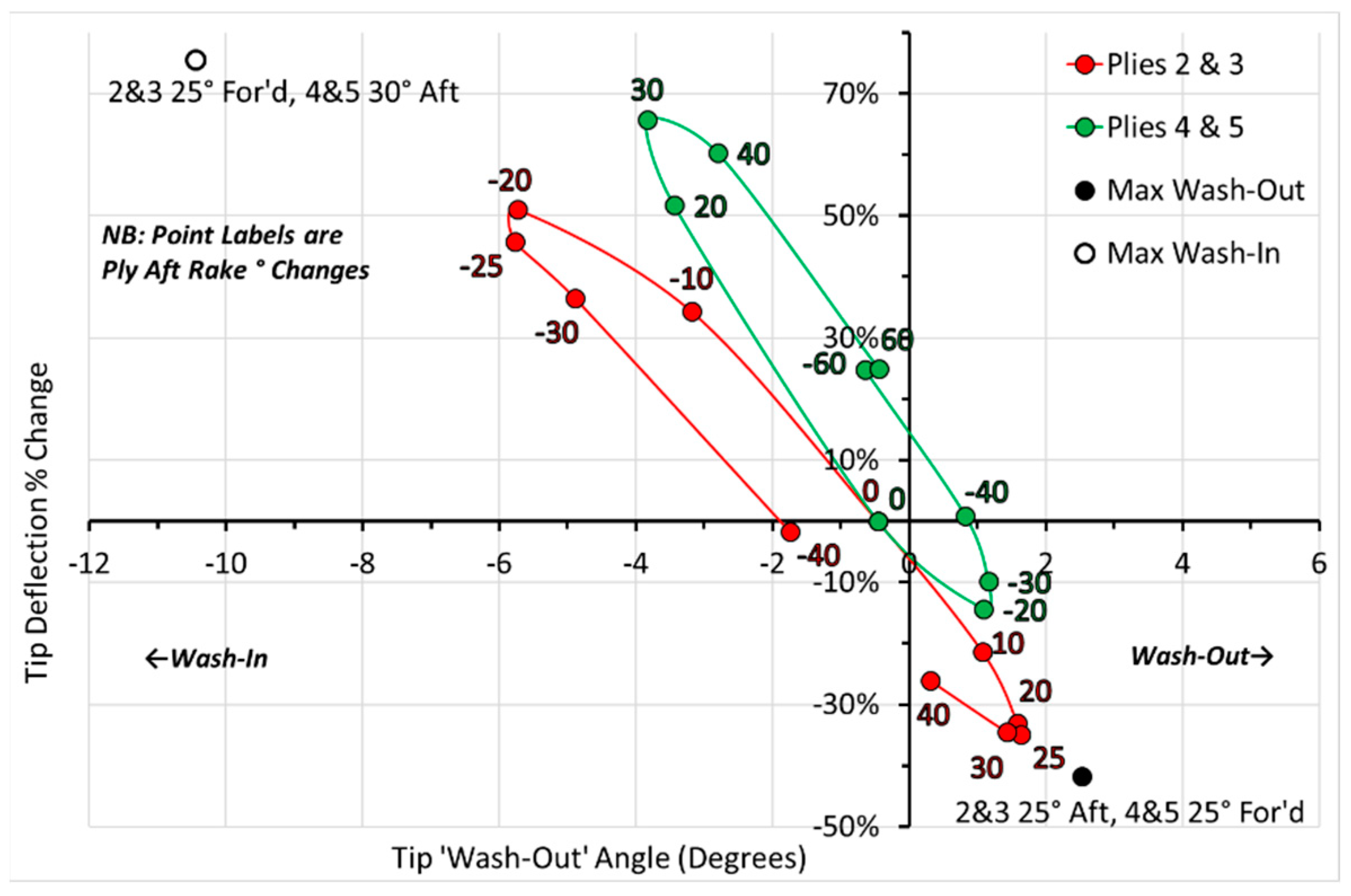
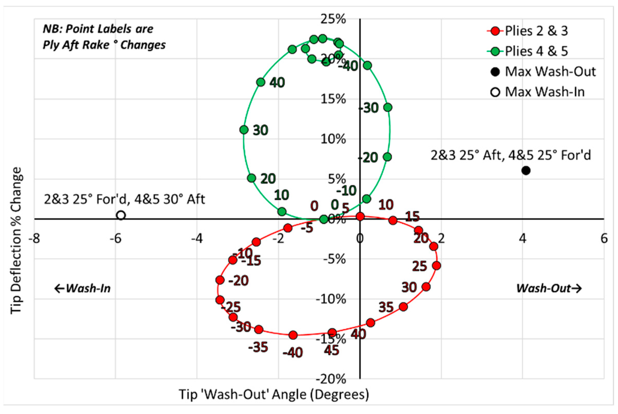
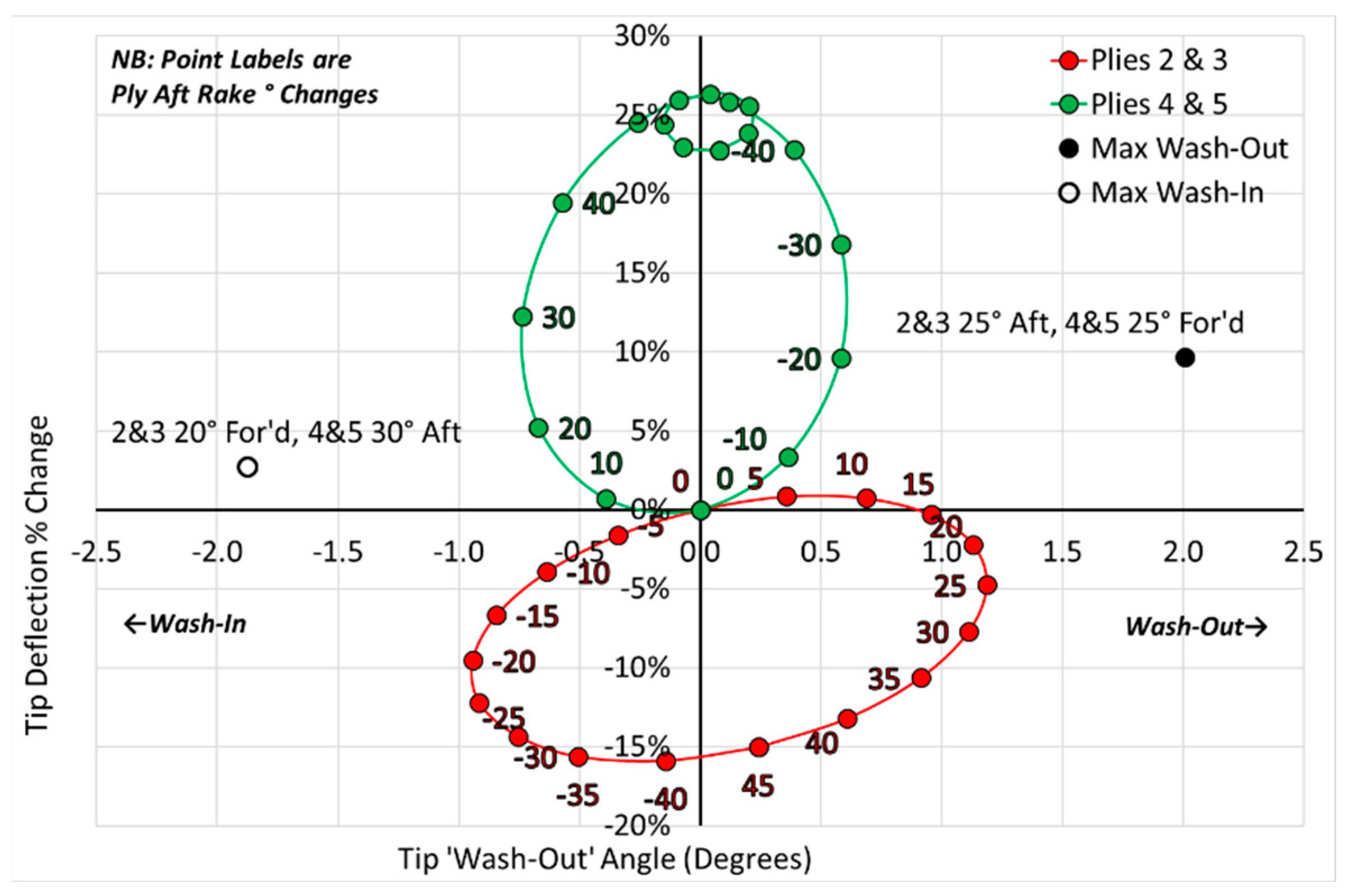
4. Passive Tip Control
5. Conclusions
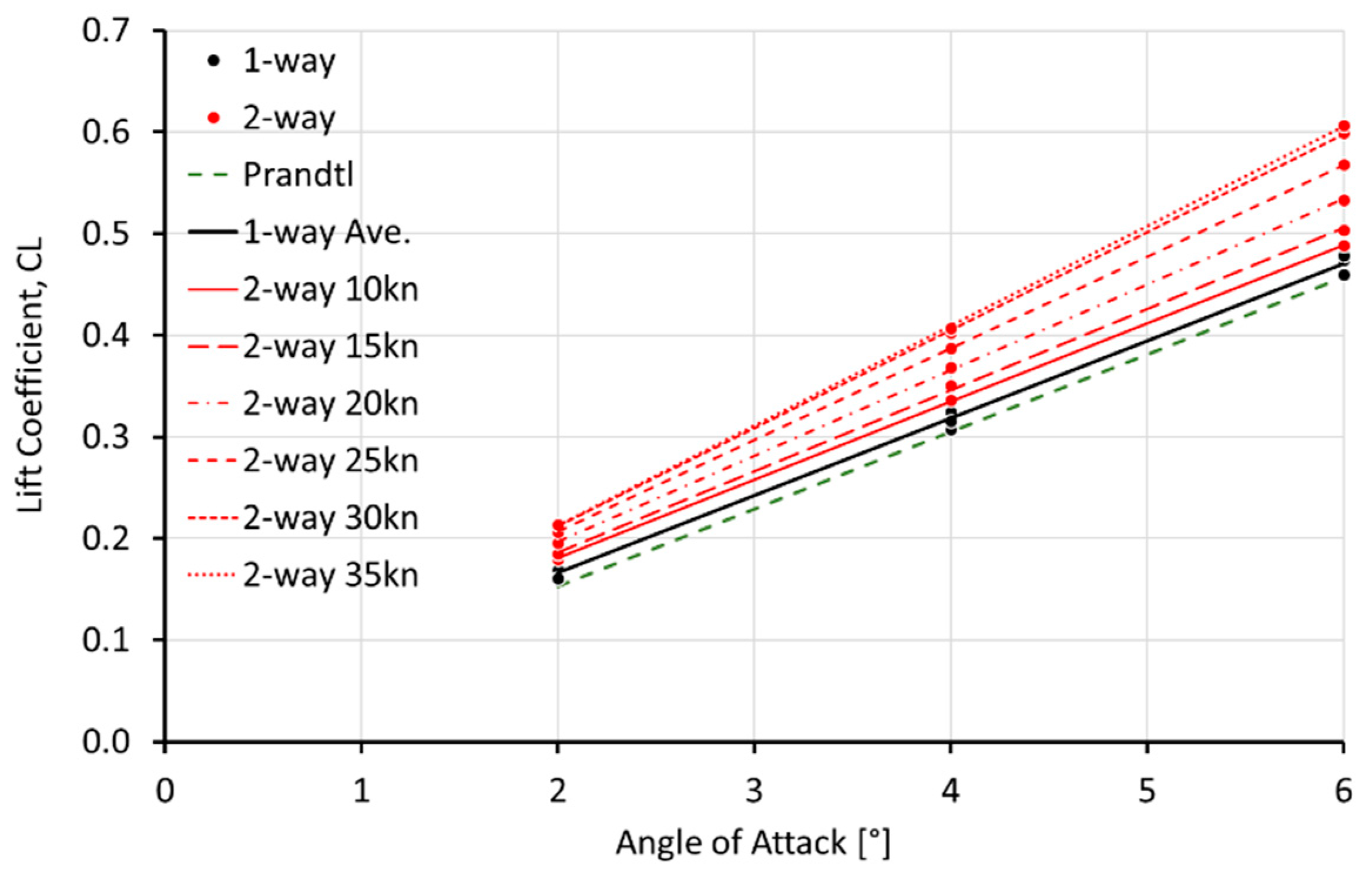
- The two-way FSI predicted more ‘lift’ force than did the simple one-way analysis.
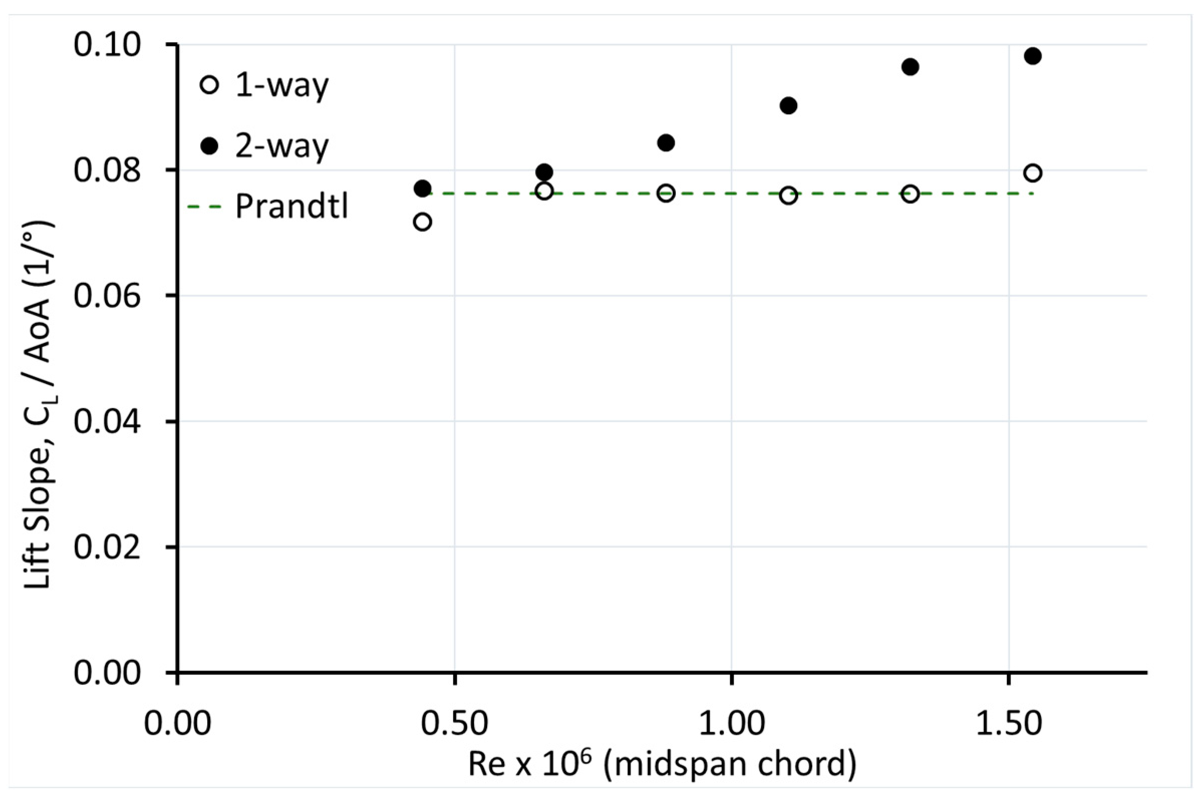
- The one-way analysis and the Prandtl equation gave very similar predictions of ‘lift’ coefficient for all velocities, whereas the full two-way FSI predicted increasing lift coefficient and slope with Reynolds number.
- Both approaches predicted a decreasing drag coefficient with increasing Reynolds number, but the two-way FSI value was lower than that of the one-way analysis.
- The one-way analysis FSI predicted tip wash-in that increased both with AoA and velocity. The two-way FSI predicted significantly less tip wash-in, which decreased at higher velocities and even switched to wash-out at lower AoAs.
- Tip deflections were slightly higher for the two-way FSI than for the one-way analysis.
Author Contributions
Funding
Institutional Review Board Statement
Informed Consent Statement
Data Availability Statement
Conflicts of Interest
References
- Appeal, C.O. Windsurfing International Inc. v. Tabur Marine (Great Britain) Ltd. Rep. Patent, Des. Trade Mark Cases 1985, 102, 59–82. [Google Scholar] [CrossRef]
- World Sailing Speed Record Council, 500 Metre Records. 2021. Available online: https://www.sailspeedrecords.com/500-metre (accessed on 12 April 2021).
- Sutherland, L.S. Windsurfer Fin Hydrodynamics. Master’s Thesis, University of Southampton, UK, 1993. [Google Scholar]
- Sutherland, L.S.; Wilson, P.A. Windsurfer Fin Hydrodynamics. In Marine, Offshore and Ice Technology; Computational Mechanics Publications; WIT Press: Southampton UK, 1994; pp. 51–58. [Google Scholar] [CrossRef]
- Broers, C.; Chiu, T.W.; Pourzanjani, M.M.A.; Buckingham, D.J. Effects of Fin Geometry and Surface Finish on Sailboard Performance and Manoeuvrability. In Manoeuvering Control Mar. Craft MCMC 92, Computational Mechanics Publications; Wilson, P.A., Ed.; WIT Press: Southampton, UK, 1992; pp. 275–289. [Google Scholar]
- Chiu, T.W.; van den Bersselaar, T.; Broers, C.; Buckingham, D.J. The Effects of Tip Flexibility on the Performance of a Blade-Type Windsurfer Fin. In Manoeuvering Control Mar. Craft MCMC 92; Computational Mechanics Publications; WIT Press: Southampton, UK, 1992; pp. 261–274. [Google Scholar]
- Chiu, T.W.; Broers, C.; Walker, A.; Baller, C. An experimental study of the effects of deformable tip on the performance of fins and finite wings. In Proceedings of the 23rd Fluid Dynamics, Plasmadynamics, and Lasers Conference, Orlando, FL, USA, 6–9 July 1993; American Institute of Aeronautics and Astronautics: Reston, VA, USA, 1993. [Google Scholar] [CrossRef]
- Fagg, S.; Velay, X. Simulating the operation of a novel variable camber hydrofoil. In Proceedings of the 1996 IEEE Aerospace Applications Conference, Aspen, CO, USA, 10–10 February 1996; Volume 3, pp. 261–271. [Google Scholar] [CrossRef]
- Fagg, S.; Velay, X. The development of a novel composite material hydrofoil through advanced computational techniques. WIT Trans. Eng. Sci. 1996, 10, 11. Available online: http://www.witpress.com/elibrary/wit-transactions-on-engineering-sciences/10/8836 (accessed on 29 March 2017).
- Fagg, S. The Development of a Reversible and Finitely Variable Camber Windsurf Fin. Ph.D. Thesis, Bournemouth University, Poole, UK, 1997. Available online: http://eprints.bournemouth.ac.uk/12235/ (accessed on 12 August 2022).
- Kunoth, A.; Schlichtenmayer, M.; Schneider, C. Speed windsurfing: Modeling and numerics. Int. J. Numer. Anal. Model. 2007, 4, 548–558. [Google Scholar]
- ABAQUS, Abaqus Unified FEA-3DEXPERIENCE R2018. 2018. Available online: www.3ds.com (accessed on 1 August 2022).
- Robert McNeel & Associates. Rhinoceros 3D; Robert McNeel & Associates: Seattle, WA, USA, 2010. [Google Scholar]
- Barbero, E.J. Finite Element Analysis of Composite Materials Using Abaqus; CRC Press; Taylor & Francis Group: Boca Raton, FL, USA, 2013. [Google Scholar]
- ABAQUS Analysis User’s Guide; Dassault Systèmes Simulia Corp: Providence, RI, USA, 2013.
- Smith, C.S. Design of Marine Structures in Composite Materials; Elsevier Ltd.: Barking, UK, 1990. [Google Scholar]
- Sleight, S. Modern Boat Building Materials; Conway Maritime Press Ltd.: London, UK, 1985. [Google Scholar]
- ANSYS© 2022 R1, ANSYS Inc.: Cannonsburg, PA, USA, 2020.
- Shenoi, R.A.; Wellicome, J.F. West European Graduate Education Marine Technology. In Composite Materials in Maritime Structures; Volume 1 Fundamental Aspects; Cambridge University Press: Cambridge, UK; New York, NY, USA, 1993. [Google Scholar]
- Chamis, C.C. Simplified Composite Micromechanics Equations for Hygral, Thermal and Mechanical Properties. In Proceedings of the Thirty-eighth Annual Conference of the Sodety of the Plastics Industry (SPI) Reinforced Plastics/Composites Institute, Houston, TX, USA, 7–11 February 1983; p. 19. [Google Scholar]
- Chamis, C.C. Mechanics of Composite Materials Past, Present, and Future; NASA: Blacksburg, VA, USA, 1984; p. 41.
- Vignoli, L.L.; Savi, M.A.; Pacheco, P.M.; Kalamkarov, A.L. Comparative analysis of micromechanical models for the elastic composite laminae. Compos. Part B Eng. 2019, 174, 106961. [Google Scholar] [CrossRef]
- Roopa, T.; Murthy, H.N.; Sudarshan, K.; Nandagopan, O.; Kumar, A.; Krishna, M.; Angadi, G. Mechanical properties of vinylester/glass and polyester/glass composites fabricated by resin transfer molding and hand lay-up. J. Vinyl Addit. Technol. 2014, 21, 166–173. [Google Scholar] [CrossRef]
- Abdelal, N.; Donaldson, S.L. Comparison of methods for the characterization of voids in glass fiber composites. J. Compos. Mater. 2017, 52, 487–501. [Google Scholar] [CrossRef]
- Nascimento, F. Windsurf Fin- Numerical and Experimental Analysis of Ultimate Strength. Master’s Thesis, Instituto Superior Técnico, Lisbon, Portugal, 2017. [Google Scholar]
- Altmann, A.; Gesell, P.; Drechsler, K. Strength prediction of ply waviness in composite materials considering matrix dominated effects. Compos. Struct. 2015, 127, 51–59. [Google Scholar] [CrossRef]
- Saldanha, A.R.Q. Hydrodynamic and Fluid-Structure Interaction analysis of a Windsurf Fin. Master’s Thesis, Instituto Superior Técnico, Lisbon, Portugal, 2019. [Google Scholar]
- Siemens. Simcenter STAR-CCM+; Siemens: Munich, Germany, 2018. [Google Scholar]
- Wang, Z.; Wang, Y.; Zhuang, M. Improvement of the aerodynamic performance of vertical axis wind turbines with leading-edge serrations and helical blades using CFD and Taguchi method. Energy Convers. Manag. 2018, 177, 107–121. [Google Scholar] [CrossRef]
- Nayar, K.G.; Sharqawy, M.H.; Banchik, L.D.; Lienhard, V.J.H. Thermophysical properties of seawater: A review and new correlations that include pressure dependence. Desalination 2016, 390, 1–24. [Google Scholar] [CrossRef] [Green Version]
- Siemens Star-CCM+User Guide; Siemens: Munich, Germany, 2018.
- Abbott, I.H.; von Doenhoff, A.E. Theory of Wing Sections, Including a Summary of Airfoil Data; McGraw-Hill: New York, NY, USA, 1959. [Google Scholar]
- Munson, B.R.; Okiishi, T.H.; Huebsch, W.W. Fundamentals of Fluid Mechanics, 6th ed.; J. Wiley & Sons: Hoboken, NJ, USA, 2009. [Google Scholar]
- Stodieck, O.; Cooper, J.E.; Weaver, P. Interpretation of Bending/Torsion Coupling for Swept, Nonhomogenous Wings. J. Aircr. 2016, 53, 892–899. [Google Scholar] [CrossRef]
- Tatham, R. Shear Centre, Flexural Centre and Flexural Axis: An Attempt to Clear up Current Confusion and Provide Definitions Differentiating Between the Three Terms. Aircr. Eng. Aerosp. Technol. 1951, 23, 209–210. [Google Scholar] [CrossRef]
- McAlister, K.W.; Takahashi, R.K. NACA 0015 Wing Pressure and Trailing Vortex Measurements, (n.d.) 142; NASA: Washington, DC, USA, 1991.
- Ong, C.-H.; Tsai, S.W. Design, Manufacture and Testing of A Bend-Twist D-Spar, Sandia National Laboratories. 1999. Available online: http://infoserve.sandia.gov/sand_doc/1999/991324.pdf (accessed on 23 March 2017).
- Fedorov, V. Bend-Twist Coupling Effects in Wind Turbine Blades. Ph.D. Thesis, Technical University of Denmark, Lyngby, Denmark, 2012. Available online: https://core.ac.uk/reader/13803642 (accessed on 1 August 2022).
- Barbero, E.J. Introduction to Composite Materials Design, 2nd ed.; CRC Press: Boca Raton, FL, USA, 2011. [Google Scholar]
- Strong, A.B. Fundamentals of Composites Manufacturing: Materials, Methods and Applications, 2nd ed.; Society of Manufacturing Engineers: Dearborn, MI, USA, 2008. [Google Scholar]
- Jones, R. Mechanics of Composite Materials, 2nd ed.; Taylor & Francis: Philadelphia, PA, USA, 1999. [Google Scholar]
- Caprino, G.; Visconti, I.C. A Note on Specially Orthotropic Laminates. J. Compos. Mater. 1982, 16, 395–399. [Google Scholar] [CrossRef]
- Fedorov, V.A.; Dimitrov, N.; Berggreen, C.; Krenk, S.; Branner, K.; Berring, P. Investigation of Structural Behavior due to Bend-Twist Couplings in Wind Turbine Blades; NAFEMS NORDIC Seminar: Esbjerg, Denmark, 2010. [Google Scholar]
- Krone, N., Jr. Divergence elimination with advanced composites. In Proceedings of the Aircraft Systems and Technology Meeting, Los Angeles, CA, USA, 4–7 August 1975; American Institute of Aeronautics and Astronautics: Los Angeles, CA, USA, 1975. [Google Scholar] [CrossRef]
- Johnsen, F.A. Sweeping Forward: Developing & Flight Testing the Grumman X-29A Forward Swept Wing Research Aircraft; National Aeronautics and Space Administration; Aeronautics Research Mission Directorate: Washington, DC, USA, 2013.
- Wansack, J.K. X-29 Advanced Technology Demonstrator Technical Activity Report; USAF Flight Dynamics Laboratory: Wright-Patterson Air Force Base, OH, USA, 1983.
- Kooijman, H.J.T. Bending-Torsion Coupling of a Wind Turbine Rotor Blade; ECN: Amsterdam, The Netherlands, 1996; Available online: https://www.ecn.nl/publications/ECN-I--96-060 (accessed on 1 August 2022).
- de Goeij, W.; van Tooren, M.; Beukers, A. Implementation of bending-torsion coupling in the design of a wind-turbine rotor-blade. Appl. Energy 1999, 63, 191–207. [Google Scholar] [CrossRef]
- Lobitz, D.W.; Veers, P.; Eisler, G.R.; Laino, D.J.; Miglior, P.G.; Bir, G. The Use of Twist-Coupled Blades to Enhance the Performance of Horizontal Axis Wind Turbines; Sandia Report No. SAND2001-1303; Sandia National Labs: Albuquerque, NM, USA, 2001.
- Lobitz, D.W.; Veers, P.S. Load Mitigation with Bending/Twist-coupled Blades on Rotors using Modern Control Strategies. Wind Energy 2002, 6, 105–117. [Google Scholar] [CrossRef]
- Capellaro, M. Design Challenges for Bend Twist Coupled Blades for Wind Turbines: And Application to Standard Blades. 2012. Available online: http://energy.sandia.gov/wp-content/gallery/uploads/2B-B-1-Capellaro1.pdf (accessed on 23 March 2017).
- Sompong, N. Effects of bend-twist coupling deformation on the aerodynamic performance of a wind turbine blade. Int. J. Geomate. 2017, 12, 15–20. [Google Scholar] [CrossRef]
- Nicholls-Lee, R.; Turnock, S.; Boyd, S. Application of bend-twist coupled blades for horizontal axis tidal turbines. Renew. Energy 2012, 50, 541–550. [Google Scholar] [CrossRef]
- Nicholls-Lee, R.F.; Boyd, S.W.; Turnock, S.R. Development of high performance composite bend-twist coupled blades for a horizontal axis tidal turbine. In Proceedings of the ICCM17: 17th International Conference on Composite Materials, Edinburgh, UK, 27–31 July 2009; Available online: http://eprints.soton.ac.uk/67325 (accessed on 23 March 2017).
- Liu, Z.; Young, Y.L. Utilization of bend–twist coupling for performance enhancement of composite marine propellers. J. Fluids Struct. 2009, 25, 1102–1116. [Google Scholar] [CrossRef]
- Young, Y. Fluid–structure interaction analysis of flexible composite marine propellers. J. Fluids Struct. 2008, 24, 799–818. [Google Scholar] [CrossRef]
- Blasques, J.P.; Berggreen, C.; Andersen, P. Hydro-Elastic Tailoring and Optimization of a Composite Marine Propeller. In Proceedings of the 13. European Conference on Composite Materials: Composites for Sustainable Progress, Stockholm, Sweden, 2–5 June 2008; p. 10. [Google Scholar]
- Lin, H.J.; Lai, W.M.; Kuo, Y.M. Effects of Stacking Sequence on Nonlinear Hydroelastic Behavior of Composite Propeller Blade. J. Mech. 2010, 26, 293–298. [Google Scholar] [CrossRef]
- Mulcahy, N.L.; Prusty, G.; Gardiner, C.P. Hydroelastic tailoring of flexible composite propellers. Ships Offshore Struct. 2010, 5, 359–370. [Google Scholar] [CrossRef]
- Ahmed, A.; Wei, L. Theoretical and experimental methods on bend-twist coupling and damping properties with the relationship to lay-up of the composite propeller marine: A review. Int. J. Eng. Sci. Technol. 2012, 1, 2907–2917. [Google Scholar]
- Young, Y.L.; Garg, N.; Brandner, P.A.; Pearce, B.W.; Butler, D.; Clarke, D.; Phillips, A.W. Load-dependent bend-twist coupling effects on the steady-state hydroelastic response of composite hydrofoils. Compos. Struct. 2018, 189, 398–418. [Google Scholar] [CrossRef]
- Giovannetti, L.M.; Banks, J.; Boyd, S.; Turnock, S.; Zingoni, A. Developing tools for assessing the fluid structure interaction of passive adaptive composite foils. In Insights and Innovations in Structural Engineering, Mechanics and Computation; Taylor & Francis Group: Oxfordshire, UK, 2016; pp. 586–591. [Google Scholar] [CrossRef]
- Giovannetti, L.M.; Banks, J.; Ledri, M.; Boyd, S.; Turnock, S. Fluid structure interaction design development of passive adaptive composite international moth foil. In Proceedings of the International Conference on Innovation in High Performance Sailing Yachts 4th Edition, Lorient, France, 28–30 June 2017; Available online: https://eprints.soton.ac.uk/412152/ (accessed on 1 August 2022).
- Giovannetti, L.M. Fluid Structure Interaction Testing, Modelling and Development of Passive Adaptive Composite Foils. Ph.D. Thesis, University of Southampton, Southampton, UK, 2017. Available online: https://eprints.soton.ac.uk/412651/ (accessed on 1 August 2022).
- Giovannetti, L.M.; Banks, J.; Ledri, M.; Turnock, S.; Boyd, S. Toward the development of a hydrofoil tailored to passively reduce its lift response to fluid load. Ocean Eng. 2018, 167, 1–10. [Google Scholar] [CrossRef]
- Temtching, V.; Augier, B.; Dalmas, T.; Fagherazzi, O.; Dumergue, N. Analysis of Composite Layup Impact on Hydrodynamic Performances of Sail Yacht Flexible Hydrofoils. In Proceedings of the JH2018—16th Journées de l’Hydrodynamique., Marseille, France, 27–29 November 2018; p. 15. [Google Scholar]
- Temtching, V.; Augier, B. Bend-Twist Coupling Analysis of Composite Hydrofoils with FSI. In Proceedings of the 24th Congr. Francais Mec., Brest, France, 26–30 August 2019. [Google Scholar]
- Temtching, V.; Navale, E.; Augier, B.; Dalmas, T.; Dumergue, N.; Paillard, B. Impact of Composite Layup on Hydrodynamic Performances of a Surface Piercing Hydrofoil. In Proceedings of the 23rd Chesap. Sail. Yacht Symp., Annapolis, MD, USA, 15–16 March 2019; p. 15. [Google Scholar]
- Vanilla, T.T.; Benoit, A.; Benoit, P. Hydro-elastic response of composite hydrofoil with FSI. Ocean Eng. 2021, 221, 108230. [Google Scholar] [CrossRef]


| UD Epoxy/e-Glass | UD Epoxy/Carbon | Woven Epoxy/Carbon | |
|---|---|---|---|
| E1 (Pa) | 2.23 × 10¹⁰ | 5.66 × 10¹⁰ | 2.84 × 10¹⁰ |
| E2 (Pa) | 7.90 × 10⁹ | 5.11 × 10⁹ | 2.84 × 10¹⁰ |
| E3 (Pa) | 7.90 × 10⁹ | 5.11 × 10⁹ | 5.54 × 10⁹ |
| ν12 | 0.29 | 0.31 | 0.04 |
| ν23 | 0.40 | 0.42 | 0.30 |
| ν13 | 0.29 | 0.31 | 0.30 |
| G12 (Pa) | 4.12 × 10⁹ | 3.26 × 10⁹ | 3.30 × 10⁹ |
| G23 (Pa) | 3.50 × 10⁹ | 3.08 × 10⁹ | 2.70 × 10⁹ |
| G13 (Pa) | 4.12 × 10⁹ | 3.26 × 10⁹ | 2.70 × 10⁹ |
| Base size | 50 mm |
| Domain relative cell size | 150% |
| VOR 3 relative cell size | 50% |
| VOR 2 relative cell size | 10% |
| VOR 1 relative cell size | 3% |
| Number of prism layers | 25 |
| Prism layer thickness | 2 mm |
| Prism layer stretching | 1.17 |
| Wall y+ | ≈1 |
| Number of xells | ≈ 3 × 10⁶ |
Publisher’s Note: MDPI stays neutral with regard to jurisdictional claims in published maps and institutional affiliations. |
© 2022 by the authors. Licensee MDPI, Basel, Switzerland. This article is an open access article distributed under the terms and conditions of the Creative Commons Attribution (CC BY) license (https://creativecommons.org/licenses/by/4.0/).
Share and Cite
Cardoso de Brito, M.; Sutherland, L.S.; Pereira, J.M.C.; Arruda, M.R. Fluid-Structure Interaction Analyses for Hydro-Elastic Tailoring of a Windsurfer Fin. J. Mar. Sci. Eng. 2022, 10, 1371. https://doi.org/10.3390/jmse10101371
Cardoso de Brito M, Sutherland LS, Pereira JMC, Arruda MR. Fluid-Structure Interaction Analyses for Hydro-Elastic Tailoring of a Windsurfer Fin. Journal of Marine Science and Engineering. 2022; 10(10):1371. https://doi.org/10.3390/jmse10101371
Chicago/Turabian StyleCardoso de Brito, Miguel, Leigh Stuart Sutherland, José Manuel C. Pereira, and Mário Rui Arruda. 2022. "Fluid-Structure Interaction Analyses for Hydro-Elastic Tailoring of a Windsurfer Fin" Journal of Marine Science and Engineering 10, no. 10: 1371. https://doi.org/10.3390/jmse10101371