Article

Research on Path Tracking of Articulated Steering Tractor Based on Modified Model Predictive Control

1
College of Engineering, China Agricultural University, Beijing 100083, China
2
Beijing Institute of Space Launch Technology, Beijing 100076, China
*
Author to whom correspondence should be addressed.
Agriculture 2023, 13(4), 871; https://doi.org/10.3390/agriculture13040871
Submission received: 21 March 2023 / Revised: 11 April 2023 / Accepted: 13 April 2023 / Published: 15 April 2023

Abstract

:
With the development of agricultural mechanization and information technology, automatic navigation tractors are becoming a more common piece of farm equipment. The accuracy of automatic navigation tractor path tracking has become critical for maximizing efficiency and crop yield. Aiming at improving path tracking control accuracy and the real-time performance of the traditional model predictive control (MPC) algorithm, the study proposed an adaptive time-domain parameter with MPC in the path tracking control of the articulated steering tractor. Firstly, the kinematics model of the articulated steering tractor was established, as well as the multi-body dynamics model by RecurDyn. Secondly, the genetic algorithm was combined with MPC. The genetic algorithm was used to calculate the optimal time domain parameters under real-time vehicle speed, vehicle posture and road conditions, and the adaptive MPC was realized. Then, path tracking simulations were conducted by combining RecurDyn and Simulink under different path types. Compared with the traditional MPC algorithm under the three paths of U-shaped, figure-eight-shaped and complex curves, the maximum lateral deviations of the modified MPC algorithm were reduced by 59.0%, 24.9% and 13.2%, respectively. At the same time, the average lateral deviation was reduced by 72%, 43.5% and 20.3%, respectively. Finally, the real path tracking tests of the articulated steering tractor were performed. The test results indicated that under the three path tracking conditions of straight line, front wheel steering and articulated steering, the maximum lateral deviation of the modified MPC algorithm was reduced by 67.8%, 44.7% and 45.1% compared with the traditional MPC. The simulation analysis and real tractor tests verified the proposed MPC algorithm, considering the adaptive time-domain parameter has a smaller deviation and can quickly eliminate the deviation and maintain tracking stability.

1. Introduction

The front and rear body of the articulated steering tractor can be relatively deflected, resulting in an excellent passing ability, small turning radius and convenient operation, which has been widely utilized in orchards and small-pitch farmland [1,2]. In recent years, with the rapid development of satellite navigation, sensors and control technology, the research on autonomous navigation agricultural equipment has also grown rapidly [3]. The automatic navigation control technology of agricultural machinery has become an important factor in liberating productivity and realizing agricultural automation [4,5]. It is of great significance to investigate the automatic navigation of the articulated steering tractor for improving the orchard intellectualization and unmanned technology [6,7].
The path tracking control algorithm is the key to automatic navigation technology of agricultural equipment [8]. With a complex structure and strong nonlinearity, the path tracking control of articulated steering vehicles is more difficult than that of ordinary vehicles. At present, the commonly used path tracking control algorithms include the pure tracking control algorithm, linear feedback control algorithm, Stanley control algorithm, model predictive control (MPC) algorithm and so on [9,10]. The MPC algorithm has the advantage of predicting future trajectories and handling multiple constraints, which has been widely employed in path tracking control. In the application, there are three essential steps in MPC, i.e., the model prediction, rolling optimization and feedback correction. The most obvious advantage of MPC is that it can add multiple constraints in the control process, since these constraints play an influential role in the planning and control of vehicle motion [11,12,13,14,15]. MPC solves an optimal control problem (OCP) to get a sequence of control commands over a finite receding horizon that optimizes a certain control metric (objective); then, the first portion of the resulting sequence is applied to the system. The main advantage of using MPC for path following in comparison with the non-predictive controllers presented above is the ability of MPC to handle constrained and nonlinear systems and it has been widely adopted in path tracking.
Beal et al. used the model prediction algorithm to design the path tracking controller. The stability boundary was determined according to the maximum available tire force to ensure the driving stability of the vehicle in the process of tracking the path [16]. Arun et al. established a path tracking control model based on MPC and vehicle dynamics, and it was implemented in a simulation with a car-sim model [17]. Zhang et al. applied the state lattice method to the upper trajectory planning controller and designed an MPC controller for path tracking based on the kinematic model [18]. Ji et al. used a 3D virtual dangerous potential field and designed the path tracking controller using the multi-constrained MPC method [19]. These studies that applied MPC have achieved excellent results; however, these studies all applied MPC to road vehicles with a good working environment, and the effect would be worse when they were applied to agricultural vehicles with a bad working environment. Therefore, the improved application of the MPC control scheme has also been favored by researchers. Considering the lateral and heading deviation to the reference trajectory, Mata et al. presented a tube-based robust MPC approach [20]. Wei et al. designed nonlinear MPC based on corridors to realize smooth and comfortable track control [21]. Based on the steering geometric constraints, Liu proposed a path planning algorithm based on local deviation correction, which contains a new following vehicle distance solving algorithm to improve the accuracy of seismic vehicle path tracking [22,23,24,25]. Based on the MPC algorithm, Bai et al. proposed two optimization schemes to reduce the number of control steps or reduce the control frequency. The results indicated that the path control accuracy was higher by reducing the number of control steps. Meanwhile, the control frequency was also reduced to meet the real-time requirements, while the error was slightly larger than that of the reduced control step scheme [26]. Furthermore, Meng et al. constructed the MPC controller based on preview distance. The simulation tests proved the enhanced accuracy and stability of path tracking [27]. For path tracking control of articulated vehicles, Li et al. designed an MPC controller based on the dynamic model by considering the multi-point preview error of the path [28], which can effectively improve the path tracking accuracy of articulated vehicles. Joseph et al. considered a model predictive path following control (MPFC). The closed-loop asymptotic stability under MPFC without terminal constraints or costs is rigorously proven and a stabilizing-horizon length is calculated. The analysis is based on verifying the cost-controllability assumption by deriving an upper bound of the MPFC value function with a finite prediction horizon [29]. Yue et al. proposed a model free predictive control (MFAPC) strategy using particle swarm optimization (PSO) to overcome structural and unstructured uncertainties. The control scheme of MFAPC is improved by integrating vehicle state parameters. The experimental results show that the proposed scheme does not require an accurate mathematical model and can quickly track the reference path [30]. Nevertheless, the real-time problem of time-domain parameters in MPC was rarely considered in these research studies. The setting of time-domain parameters is mostly fixed and not updated with the real-time status of vehicles, which diminishes the path tracking accuracy and the applicability.
In this paper, in order to improve the real-time performance of MPC, the study proposed an adaptive time-domain parameter with MPC. We modified the MPC by combining the genetic algorithm. The genetic algorithm was employed to calculate the optimal time-domain parameters under real-time vehicle speed, vehicle attitude and road conditions. The effectiveness and superiority of the new algorithm was verified through co-simulation of path tracking and real tractor tests.

2. Materials and Methods

2.1. Kinematics Model of the Articulated Steering Tractor

In the study, the articulated steering tractor has two steering modes, i.e., front wheel steering and articulated steering. When the steering terrain can satisfy the steering requirements, then only front wheel steering is adopted. Conversely, the articulated steering method is involved. In the following parts, the front wheel steering kinematic model and the articulated steering kinematic model are constructed separately.

2.1.1. Front Wheel Steering Kinematic Model

It is assumed that the articulated steering tractor does not have lateral slip and roll, as well as the interaction between the tires and the ground. The kinematic model of front wheel steering of the articulated steering tractor can be simplified into a two-wheel vehicle model with two degrees of freedom. The kinematic relationship of front wheel steering is shown in Figure 1.
The rear axle center of the articulated steering tractor is depicted in coordinates (x, y). The components of velocity v in the X and Y axes can be calculated as follows.
x ˙ = v c o s ψ
y ˙ = v s i n ψ
The change rate of the heading angle can be calculated by,
ψ ˙ = v t a n δ l
The motion equation of the articulated steering tractor with the front wheel steering mode is shown as follows.
x ˙ y ˙ ψ ˙ = v c o s ψ s i n ψ tan δ l
where v is speed of rear wheel (m/s), x ˙ is the component of v in the X-axis direction (m/s), y ˙ is the component of v in the Y-axis direction (m/s), ψ is heading angle (°), ψ ˙ is rate of change of heading angle (rad/s2), δ is front wheel turning angle (°) and l is distance from the center of the front wheel to the center of the rear wheel (m).

2.1.2. Kinematic Model of Articulated Steering

In the mode of articulated steering, the steering process of the tractor is to first turn the front wheel angle to the limit in the shortest time, and then begin articulated steering. In order to obtain the kinematic model of articulated steering, the following assumptions are adopted: The articulated angle φ remains constant under small displacement. Moreover, it is assumed that the track length does not change during the driving process. Furthermore, there is no slip between the track and the track wheel. According to the structure of the articulated steering tractor, the kinematic relationship of the articulated steering process is constructed, as shown in Figure 2.
The symbols in Figure 2 are listed as follows.
O1 is the center of the rear axle, O2 is the center of the front axle, O is the articulated steering hinge point, L1 is the distance from the hinge point to the rear axle (m), L2 is the distance from the hinge point to the front axle (m), δ1 is the maximum value of the front wheel turning angle (°), φ is the articulated steering angle (°), θ1 is the azimuth angle of the rear body (°), θ2 is the azimuth angle of the front body (°), v1 is the center speed of the rear axle (m/s) and v2 is the center speed of the front axle (m/s).
The kinematic constraints of the articulated steering tractor can be expressed as,
x ˙ 1 s i n θ 1 y ˙ 1 c o s θ 1 = 0 x ˙ 2 s i n θ 2 y ˙ 2 c o s θ 2 = 0
where x ˙ 1 is the component of v1 in the X-axis direction (m/s), y ˙ 1 is the component of v1 in the Y-axis direction (m/s), x ˙ 2 is the component of v2 in the X-axis direction (m/s) and y ˙ 2 is the component of v2 in the Y-axis direction (m/s).
The relationship between the rate of the articulated steering angle and the rate of front and rear body azimuth is shown in the following equation.
φ ˙ = θ ˙ 1 θ ˙ 2
where φ ˙ is rate of change of articulated steering angle (rad/s2), θ ˙ 1 is rate of change of the rear body azimuth (rad/s2) and θ ˙ 2 is rate of change of the front body azimuth (rad/s2).
Therefore, the relative velocity equations of the front and rear bodies can be shown as follows.
v 1 c o s φ = v 2 c o s δ 1 + θ ˙ 1 L 1 s i n φ v 1 s i n φ = θ ˙ 2 L 2 + θ ˙ 1 L 1 c o s φ + v 2 s i n δ 1
The rate of the rear body azimuth is calculated by,
θ ˙ 1 = ( s i n φ t a n δ 1 c o s φ ) v 1 + φ ˙ L 2 L 1 ( c o s φ + t a n δ 1 s i n φ ) + L 2
In the proposed method, the variable is the rate of the articulated angle denoted by ω. The articulated steering kinematic model can be expressed as Equation (9).
x ˙ 1 y ˙ 1 θ ˙ 1 φ ˙ = c o s θ 1 0 s i n θ 1 0 ( s i n φ t a n δ 1 c o s φ ) L 1 ( c o s φ + t a n δ 1 s i n φ ) + L 2 L 2 L 1 ( c o s φ + t a n δ 1 s i n φ ) + L 2 0 1 v 1 ω
Based on the aforementioned analysis, the kinematic model of the articulated steering tractor with the center of the rear axle as the control point is established.

2.2. Multi-Body Dynamics Model of the Articulated Steering Tractor

In order to verify the performance of the proposed adaptive MPC path tracking controller, a multi-body dynamics model of the articulated steering tractor was established in software RecurDyn, as shown in Figure 3. The model parameters are shown in Table 1.

2.3. Parametric Adaptive Path Tracking Controller Design

2.3.1. MPC Path Tracking Algorithm Based on Kinematic Model

It can be seen from Equations (4) and (9) that when the front wheel steers, the articulated steering tractor can be regarded as a control system with input u(v, δ ) and state quantity χ(x,y,ψ), while as a control system with input u(v,ω) and state quantity χ(x1, y1, θ1, φ) at the time of articulated steering. The following is an analytical calculation of the articulated steering process. The kinematic model of the articulated steering tractor is presented in Equation (10) [31,32].
χ ˙ = f ( χ , u )
For a planned target path, each reference point satisfies the above equation. Using r to represent the reference quantity, Equation (10) can be rewritten as,
χ ˙ r = f χ r , u r
where χ r = [χr 𝑦r θr φr], ur = [vr ωr].
After expanding Equation (10) with the Taylor series at the reference point and ignoring the higher order terms, Equation (12) can be found.
χ ˙ = f x r , u r + f ( χ , u ) χ χ χ r + f ( χ , u ) u u u r
Equation (12) minus Equation (11) obtains the linear error model of the articulated steering tractor.
χ ~ ˙ = χ ˙ χ ˙ r = A χ ~ + B u ~
where A = f ( χ , u ) χ , B = f ( χ , u ) u , χ ~ k = χ k χ r k , u ~ k = u k u r ( k ) , u ~ k is the control volume increment, k is the current sampling moment and k + 1 is the next sampling moment.
At any reference point, Equation (14) can be obtained by linear discretization of Equation (13).
χ ~ ˙ = χ ~ ( k + 1 ) χ ~ ( k ) T = A χ ~ + B u ~
where T = the control period.
The discrete state space equations of the kinematic model of the articulated steering tractor can be obtained after rectification.
χ ~ k + 1 = T A + E χ ~ k + T B u ~ k .
Transform the above model to build a new state vector.
ξ ( k | k ) = χ ~ ( k | k ) u ~ ( k 1 | k )
Then the new state space expression can be obtained as follows.
ξ k + 1 | k = χ ~ k + 1 | k u ~ k | k = A ~ B ~ 0 I 1 ξ k | k + B ~ I 1 Δ u ~ k | k = a ξ ( k | k ) b Δ u ~ ( k | k )
The output equation is by,
η ( k | k ) = I 2 0 χ ~ ( k | k ) u ~ ( k 1 | k ) = c ξ ( k | k )
where I1, I2 = unit matrices.
The output of the system in the predicted future time-domain Np can be predicted as Equation (19).
Y ( t ) = Ψ ξ ( k | k ) + Θ Δ U ( k )
where Y = η k + 1 k η k + 2 k η k + N c | k η k + N p | k , Ψ = c a c a 2 c a N c c a N p , Θ = c b 0 0 c a b c b 0 0 c a N p 1 b c a N p 2 b c a N p N C b , Δ U = Δ u ~ k k Δ u ~ k + 1 k Δ u ~ k + 2 k Δ u ~ k + N c 1 | k , Np = predicted time-domain, Nc = control time-domain.
In order to ensure that the tractor can track the target trajectory rapidly and stably, the increment of the articulated steering angle is used as the control quantity of the objective function. Therefore, the optimized objective function of the path tracking model can be drawn as follows [33,34].
J ξ k , u k 1 , Δ U k = m i n i = 1 N p   Δ η ( k + i k ) Q 2 + i = 1 N c 1   Δ u ( k + i k ) R 2 + ρ ε 2
where Δ η ( k + i k ) = η ( k + i k ) η r ( k + i k ) , Δ η ( k + i k ) = Difference between actual output and reference output, I = 1,2,…, Np.
Furthermore, Q, R and ρ are the weight matrices and ε represents the relaxation factor.

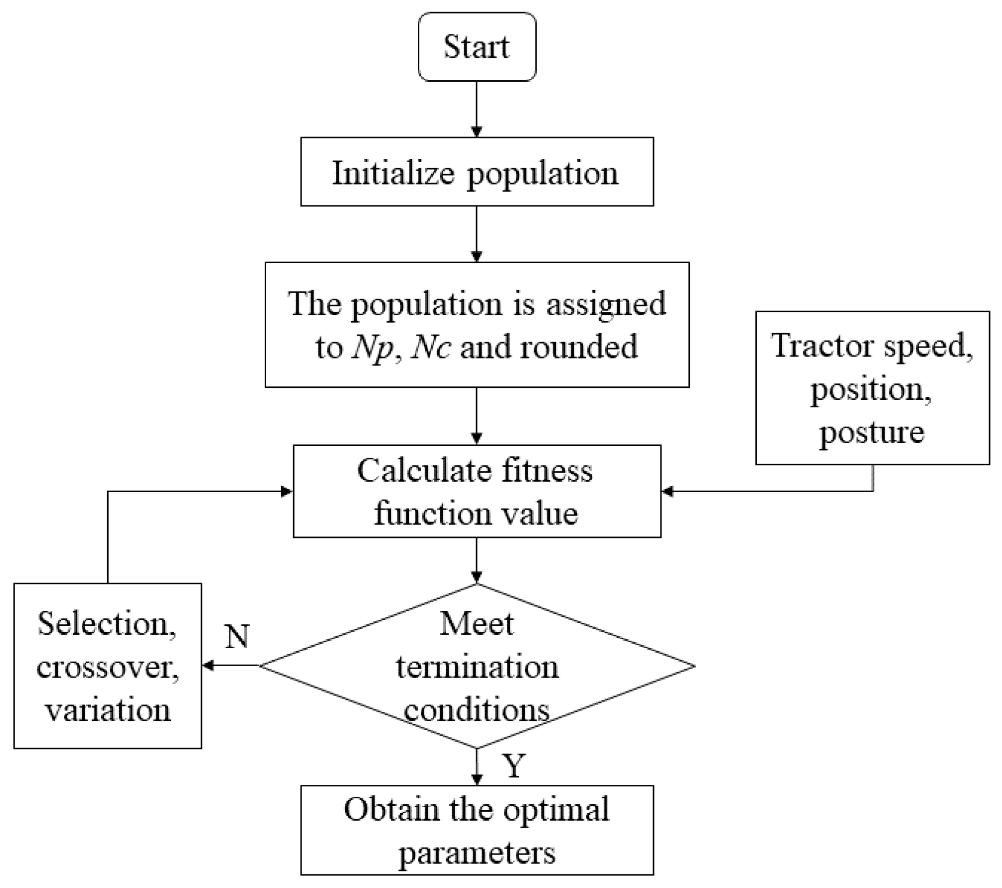
2.3.2. Genetic Algorithm to Optimize Time-Domain Parameters

In Equation (20), the prediction time-domain Np determines the length of the rolling optimization solution process. The control time-domain Nc affects the tractor’s tracking performance as well as the control speed. Therefore, the values of Np and Nc make a great impact on the path tracking performance of the unmanned tractors. However, the time-domain parameters of the traditional MPC controller are fixed at different speeds and different road conditions, which make it difficult to adapt to different road conditions. In the study, in order to obtain the optimal time-domain parameters in real time, firstly the whole path tracking process is segmented according to the system sampling frequency, and then the MPC time-domain parameters within each sampling frequency are optimized by genetic algorithm.
Furthermore, the optimization of the time-domain parameters is made by the genetic algorithm. The genetic algorithm was introduced by Professor Holland in 1975 according to the phenomena of reproduction, hybridization and mutation in nature [35]. The genetic algorithm is a stochastic global search and optimization method that imitates the mechanism of biological evolution [36,37]. By selecting high-quality individuals and eliminating inferior individuals, the law of survival of the fittest in the natural world is simulated. Reproduction, hybridization and mutation are carried out among the selected high-quality individuals. Then, the individuals with better qualities that may be produced and iterated repeatedly are selected to make the population better and better until the expected fitness value is met. The genetic algorithm uses a probabilistic mechanism for iteration with the purpose of avoiding traps in a local optimum. The genetic algorithm is not constrained by the search space and has no continuous, derivable or single-peaked requirements for the objective function. Therefore, genetic algorithms are suitable for solving multi-objective optimization problems while being scalable and convenient to combine with other algorithms [38,39].
The optimization principle of the time-domain parameters is shown in Figure 4. The steps to optimize the time-domain parameters by the genetic algorithm are as follows. Firstly, the population is initialized, in which each individual of the population will be assigned a value and rounded according to the range of time-domain parameters. Secondly, the adaptation degree of each individual is calculated by combining the information of tractor speed and position through the adaptation degree function. Finally, the optimal parameters are obtained when the termination condition is satisfied. If the termination condition is not satisfied, then selection, crossover and mutation are performed to obtain a new population and the fitness function value is calculated again.
The fitness function of the genetic algorithm is presented as follows.
L = 1 J ( ξ ( k ) , u ( k 1 ) , Δ U ( k ) )
The population size is set as 200. Furthermore, the probabilities of crossover and variation are set as 0.6 and 0.1 separately. Terminated evolutions are set at 20. To improve the optimization efficiency, the prediction time-domain is taken in the range (0, 60), and the control time-domain is taken in the range (0, 30). Finally, by optimizing the time-domain parameters within each sampling frequency, the adaptive time-domain parameters of the whole section of the path tracking can be realized.

3. Results and Discussion

3.1. Simulation Test

3.1.1. Construction of the Simulation System

To verify the performance of the proposed adaptive time-domain parametric model, the co-simulation model of RecurDyn and Simulink is established, as shown in Figure 5. The model can be divided into four parts, i.e., the tractor model to search for nearest target point, the adaptive MPC controller, and the genetic algorithm module.
The co-simulation principle is shown in Figure 6. The control performance of the adaptive MPC algorithm on the straight driving, front wheel steering and articulated steering process is verified through three paths of U-shaped, figure-eight-shaped and complex curves. These three path conditions include all the conditions of the articulated steering tractor in the actual working process of the orchard, i.e., the straight-line conditions, the front wheel steering conditions and the articulated steering conditions. The system sampling frequency is set to 0.5 s, and the tractor driving speed is set to 0.5 m/s.

3.1.2. U-Shaped Curve Path Tracking Simulation

The comparison of the tracking performance of the adaptive MPC and the traditional MPC on a U-shaped curve path is shown in Figure 7a. It can be seen that the tracking path of the adaptive MPC is more stable and smoother, and the tracking effect is also better. From Figure 7b,c, it can be seen that the maximum values of lateral deviation and heading deviation occur at the articulation of straight and curved lines. Adaptive MPC has a smaller maximum lateral deviation and maximum heading deviation than MPC. The lateral deviation and heading deviation of adaptive MPC fluctuate greatly during turning, which shows that adaptive MPC can quickly adjust the tractor to prevent the deviation from changing too much when there is a deviation. When there is a deviation in the whole path tracking process, the adaptive MPC can adjust the deviation to zero more quickly.
The deviation statistics results are shown in Table 2. It can be seen that the maximum value, average value and standard deviation of the lateral deviation of the adaptive MPC are reduced by 59.0%, 72% and 39.7% compared with the traditional MPC. At the same time, the maximum, average and standard deviations of the heading deviation decreased by 44.6%, 58.7% and 36.3%, respectively. The maximum values of lateral deviation and heading deviation occur at the articulation of straight and curved lines. From the average value and standard deviation, it can be seen that the accuracy and stability of adaptive MPC are better. Adaptive MPC significantly reduces the maximum and average values of deviation.

3.1.3. Figure-Eight-Shaped Curve Path Tracking Simulation

The comparisons of the tracking performance of the adaptive MPC and the traditional MPC on a figure-eight-shaped curve are shown in Figure 8a. It can be seen that the adaptive time-domain parameter MPC achieves a better tracking effect. From Figure 8b,c, it can be distinguished that the deviation is large at the beginning of tracking and at the junction of two circles. At this time, the adaptive MPC controller reduces the heading deviation significantly. MPC only keeps the deviation stable and does not reduce the deviation when there is a deviation. However, the adaptive MPC can quickly adjust the tractor to reduce the deviation, which further proves the superiority and accuracy of the adaptive MPC.
The deviation statistics results are shown in Table 3. It can be seen that the maximum value, average value and standard deviation of the lateral deviation of the adaptive MPC are reduced by 24.9%, 43.5% and 16.9% compared with the traditional MPC. The maximum, average and standard deviation of heading deviation decreased by 11.9%, 74.9% and 25.0%, respectively. Adaptive MPC significantly reduces the average values of lateral deviation and heading deviation. From the maximum value and Figure 8, adaptive MPC can reduce the maximum deviation more obviously when turning.

3.1.4. Complex Curve Path Tracking Simulation

The comparison of the tracking performance of the adaptive MPC and the traditional MPC on the complex curve path is shown in Figure 9a. It can be seen that the adaptive time-domain parameter MPC controller has a better tracking effect. According to Figure 9b,c, it can be seen that the maximum deviation occurs at the junction of the curve. The lateral deviation and heading deviation of articulated steering are smaller than front wheel steering. The lateral deviation and heading deviation of adaptive MPC fluctuate greatly, which shows that adaptive MPC adjusts the vehicle more times. The adaptive MPC can reduce the deviation more quickly and maintain stability when there is a deviation.
The deviation statistics results are shown in Table 4. It can be seen that the maximum value, average value and standard deviation of the lateral deviation of the adaptive MPC are reduced by 13.2%, 20.3% and 19.2% compared with the traditional MPC. The maximum, average and standard deviation of heading deviation decreased by 24.1%, 68.5% and 48.7%, respectively.

3.2. Test Verification

In order to further verify the effectiveness of the adaptive MPC controller, real tractor path tracking tests were conducted in the study. By taking the articulated steering tractor as the test platform, the test equipment consists of an industrial personal computer (IPC), display screen, satellite positioning equipment, steering controller, angle sensor and so on. The equipment utilized on the test platform are shown in Figure 10.
The path tracking test of the tractor was carried out in the standardized demonstration orchard of Shijiazhuang Xinnong Machinery Co., Ltd. (Shijiazhuang, China). The test road is well-maintained and flat, and the orchard has 10 rows of fruit trees, with a single row being about 70 m long, the average height of the fruit trees being 2.5 m and the average row spacing being 4 m. The position information and heading angle information obtained during the test were saved in the IPC. Each experiment was carried out three times. The data were exported for statistical processing after the test. The maximum, minimum, average value and standard deviation of the lateral deviation and heading deviation were obtained by data analysis software.
The principle of path tracking control is shown in Figure 11. The program of path tracking is written and compiled in the industrial control machine by Python. The position and heading angle information are obtained in real time by satellite positioning equipment, steering controller, angle sensor, etc. The front wheel and articulated angle are calculated in the industrial control computer. The control information can be obtained through the communication subprogram between the microcontroller controller and the industrial control computer, so as to control each motor to control the angle in real time.
Articulated steering tractors are mainly utilized in orchard environments. The driving path in the orchard can be divided into straight-line operating sections and headland turning sections. The effectiveness and accuracy of adaptive MPC in straight ahead, front wheel steering and articulated steering conditions need to be tested and verified. Therefore, the straight-line path, front wheel steering path and articulated steering path tracking tests were conducted in the study. The tractor driving speed was set to 0.5 m/s.

3.2.1. Straight-Line Path

The straight-line path tracking test circumstances are shown in Figure 12a. Figure 12b depicts the path tracking comparison between adaptive MPC and traditional MPC, wherein it can be seen that the adaptive MPC has a better tracking effect. Figure 12c,d presents the lateral and heading deviation comparisons. It can be seen that MPC will have a large lateral deviation and heading deviation, and the adaptive MPC deviation fluctuation is smaller. The adaptive MPC proposed in the study achieved significant reduction in the lateral and heading deviations in straight-line path tracking compared with the traditional MPC.
Table 5 presents the deviation statistics results. It can be seen that the maximum value, average value and standard deviation of the lateral deviation of the proposed adaptive MPC are reduced by 67.8%, 65.3% and 68.8%, respectively. At the same time, in comparison with the traditional MPC, the maximum, average and standard deviation of heading deviation are also decreased by 26.8%, 28.1% and 35.7%, respectively. Adaptive MPC can significantly improve lateral deviation.

3.2.2. Front Wheel Steering Path

The front wheel steering path tracking tests were conducted to verify the control effect of adaptive MPC. The front wheel steering path tracking test environment is shown in Figure 13a. Figure 13b shows the comparisons of path tracking between adaptive MPC and traditional MPC. It can be seen from Figure 13b that the adaptive MPC tracks better. Figure 13c,d presents that the lateral deviation and heading deviation of the adaptive MPC proposed in the study are significantly lower than those of the traditional MPC in the curve paths. In the latter part of the path tracking, the heading angle fluctuates greatly, which may be caused by the vibration of the tractor body. The tractor made a big deviation during the two turns. However, the deviations produced by adaptive MPC are both smaller than MPC. Adaptive MPC can adjust tractors more times, faster and better.
Table 6 depicts the deviation statistics results. It can be seen that the maximum value, average value and standard deviation of the lateral deviation of the adaptive MPC are reduced by 44.7%, 57.4% and 53.2% compared with the traditional MPC. Furthermore, the maximum, average and standard deviation of heading deviation are also decreased by 44.9%, 31.4% and 28.6%, respectively.

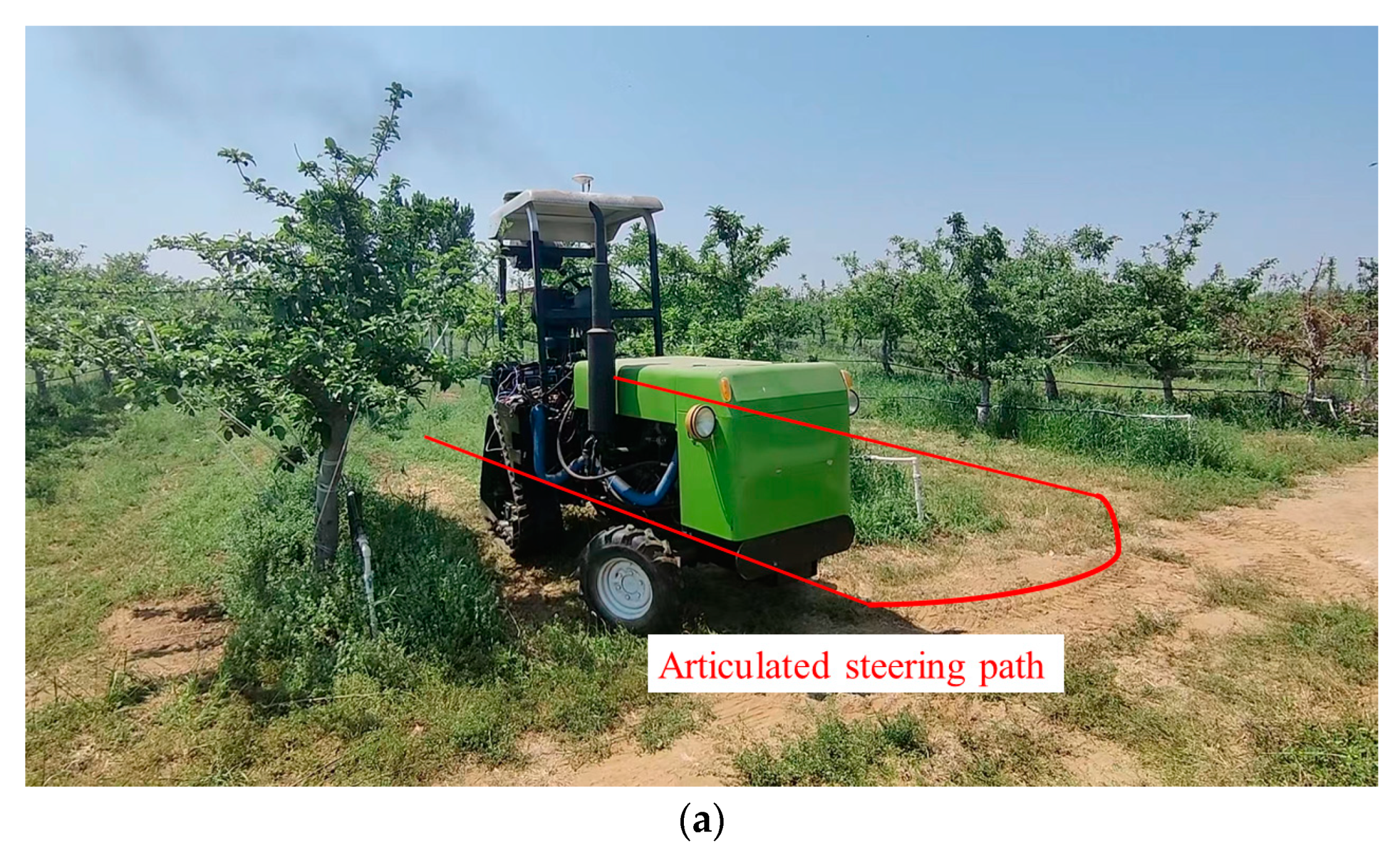
3.2.3. Articulated Steering Path

The articulated steering path tracking tests were conducted in an orchard to verify the control effect of adaptive MPC. The articulated steering path tracking environment is shown in Figure 14a. Figure 14b depicts the path tracking comparisons. From Figure 14b, it can be seen that the adaptive MPC tracks better. Figure 14c,d indicates that the adaptive MPC reduces the lateral deviation and heading deviation over the whole path compared with the traditional MPC, in which a significant reduction can be easily distinguished. In the whole path tracking process, the MPC deviation fluctuates greatly, and the adjustment speed is slow. Furthermore, after adjusting the deviation, the adaptive MPC can keep the deviation at a lower level. In the latter part of path tracking, the heading angle fluctuates greatly, but the frequency of adaptive MPC adjustment is faster and the deviation is lower. The test results further prove that traditional MPC has greater errors when used in agricultural tractors, and it needs to be improved. The adaptive MPC proposed in this study improves the path tracking accuracy when used in agricultural tractors.
Table 7 presents the specific results in path tracking of the articulated steering tractor. It can be seen that compared with the traditional MPC, the maximum value, average value and standard deviation of the lateral deviation of the adaptive MPC are reduced by 45.1%, 60.9% and 51.6%, respectively. The maximum, average and standard deviation of heading deviation are decreased by 50.2%, 34.7% and 39.2%, respectively. The average and standard deviation of lateral deviation are reduced more, which ensures the stability of tracking deviation. The heading deviation is also greatly improved, which ensures that the car body will not vibrate too violently.

4. Conclusions

In order to improve the real-time performance of MPC, the present study proposed an adaptive time-domain parameter with traditional MPC in path tracking control of the articulated steering tractor. The genetic algorithm was adopted to calculate the optimal time-domain parameters under real-time tractor speed, tractor attitude and road conditions.
The conclusions are as follows.
  • The kinematics model and multi-body dynamics model of the articulated steering tractor were established. Then, the co-simulations by RecurDyn and Simulink were conducted under a U-shaped, figure-eight-shaped and complex curves path. The maximum lateral deviations of the adaptive MPC were reduced by 59.0%, 24.9% and 13.2%, respectively. At the same time, the average lateral deviations were reduced by 72%, 43.5% and 20.3% compared with the traditional MPC. The maximum heading deviations of the adaptive MPC were reduced by 44.6%, 11.9% and 24.1%, respectively. The average lateral deviations were reduced by 58.7%, 74.9% and 68.5%.
  • Taking the articulated steering tractor as the test platform, the performance of adaptive MPC was tested in real tractors through a straight-line path, front wheel steering path and articulated steering path. The results indicated that the maximum lateral deviations of the adaptive MPC were reduced by 67.8%, 44.7% and 45.1%, respectively. Compared with the traditional MPC, the average lateral deviations of the adaptive MPC were reduced by 65.3%, 57.4% and 60.9%, respectively. The maximum heading deviations of the adaptive MPC were reduced by 26.8%, 44.9% and 50.2%, respectively. The average lateral deviations were reduced by 28.1%, 31.4% and 34.7%.
  • The results of simulations and real tractor tests show that the real-time and path tracking performance of the proposed adaptive MPC is superior to the traditional MPC. Adaptive MPC can adjust the tractor faster when deviations occur, and the adjustment frequency of adaptive MPC is faster and the effect is better. The adaptive MPC can effectively enhance the path tracking accuracy of the articulated steering tractor.

Author Contributions

Conceptualization, B.Z. and Q.Z.; methodology, B.Z. and Q.Z.; software, B.Z. and X.S.; validation, B.Z. and Q.Z.; formal analysis, B.Z. and Q.Z.; investigation, W.G. and X.S.; resources, W.G. and H.Y.; data curation, B.Z. and Q.Z.; writing—original draft preparation, B.Z. and Q.Z.; writing—review and editing, X.S., W.G. and H.Y.; visualization, B.Z. and Q.Z.; supervision, H.Y.; project administration, Q.Z.; funding acquisition, Q.Z. All authors have read and agreed to the published version of the manuscript.

Funding

This research was funded by the National Key R&D Program of China (2022YFD2001902).

Institutional Review Board Statement

Not applicable.

Data Availability Statement

The data presented in this study are available on request from the corresponding author.

Conflicts of Interest

The authors declare no conflict of interest.

References

  1. Franceschetti, B.; Rondelli, V.; Capacci, E. Lateral Stability Performance of Articulated Narrow-Track Tractors. Agronomy 2021, 11, 2512. [Google Scholar] [CrossRef]
  2. Liang, C.; Pan, K.; Zhao, M.; Lu, M. Multi-Node Path Planning of Electric Tractor Based on Improved Whale Optimization Algorithm and Ant Colony Algorithm. Agriculture 2023, 13, 586. [Google Scholar] [CrossRef]
  3. Innam, L.; Kyunghyun, L.; Jeehyong, L.; Kwanho, Y. Autonomous Greenhouse Sprayer Navigation Using Automatic Tracking Algorithm. Appl. Eng. Agric. 2015, 31, 17–21. [Google Scholar] [CrossRef]
  4. Shutske, J.M. Agricultural automation & autonomy: Safety and Risk Assessment Must be at the Forefront. J. Agromed. 2022, 28, 5–10. [Google Scholar] [CrossRef]
  5. Md-Tahir, H.; Zhang, J.; Zhou, Y.; Sultan, M.; Ahmad, F.; Du, J.; Ullah, A.; Hussain, Z.; Xia, J. Engineering Design, Kinematic and Dynamic Analysis of High Lugs Rigid Driving Wheel, a Traction Device for Conventional Agricultural Wheeled Tractors. Agriculture 2023, 13, 493. [Google Scholar] [CrossRef]
  6. Huang, Y.; Hoffmann, W.C.; Lan, Y.; Wu, W.; Fritz, B.K. Development of a Spray System for an Unmanned Aerial Vehicle Platform. Appl. Eng. Agric. 2009, 25, 803–809. [Google Scholar] [CrossRef]
  7. Wang, Z.; Xin, P.; Sun, H.T. Path Tracking of Unmanned Vehicles Based on Contraction Constraint Model Predictive Control. Control. Decis. 2022, 37, 625–634. [Google Scholar]
  8. Zheng, J.; Wang, L.; Wang, X.; Shi, Y.; Yang, Z. Parameter Calibration of Cabbages (Brassica oleracea L.) Based on the Discrete Element Method. Agriculture 2023, 13, 555. [Google Scholar] [CrossRef]
  9. DiazdelRio, F.; SanchezCuevas, P.; IñigoBlasco, P.; SevillanoRamos, J.L. Improving Tracking of Trajectories through Tracking Rate Regulation: Application to UAVs. Sensors 2022, 22, 9795. [Google Scholar] [CrossRef] [PubMed]
  10. Wu, H.C.; Zhang, H.H.; Feng, Y.X. MPC-Based Obstacle Avoidance Path Tracking Control for Distributed Drive Electric Vehicles. World Electr. Veh. J. 2022, 13, 221. [Google Scholar] [CrossRef]
  11. Zheng, K.; Zhao, X.; Han, C.; He, Y.; Zhai, C.; Zhao, C. Design and Experiment of an Automatic Row-Oriented Spraying System Based on Machine Vision for Early-Stage Maize Corps. Agriculture 2023, 13, 691. [Google Scholar] [CrossRef]
  12. Huang, Y.R.; Fu, J.H.; Xu, S.Y.; Han, T.L.; Yu, W. Research on Integrated Navigation System of Agricultural Machinery Based on RTK-BDS/INS. Agriculture 2022, 12, 1169. [Google Scholar] [CrossRef]
  13. Qiang, S.; Mao, H.P.; Guan, X.P. Numerical Simulation and Experimental Verification of the Deposition Concentration of an Unmanned Aerial Vehicle. Appl. Eng. Agric. 2019, 35, 367–376. [Google Scholar] [CrossRef]
  14. Zhang, S.; Guo, C.; Gao, Z.; Sugirbay, A.; Chen, J.; Chen, Y. Research on 2D Laser Automatic Navigation Control for Standardized Orchard. Appl. Sci. 2020, 10, 2763. [Google Scholar] [CrossRef]
  15. Kang, N.; Han, Y.; Wang, B.Y. Linear quadratic regulator based on extended state observer–based active disturbance rejection control of autonomous vehicle path following control. J. Syst. Control. Eng. 2023, 273, 102–120. [Google Scholar] [CrossRef]
  16. Beal, C.E.; Gerdes, J.C. Model Predictive Control for Vehicle Stabilization at the Limits of Handling. IEEE Trans. Control. Syst. Technol. 2013, 21, 1258–1269. [Google Scholar] [CrossRef]
  17. Arun, M.; Hiroyuki, O.; Tatsuya, S. Path tracking control using model predictive control with on GPU implementation for autonomous driving. J. Arid. Land Stud. 2018, 28, 163–167. [Google Scholar] [CrossRef]
  18. Zhang, C.; Chu, D.; Liu, S. Trajectory planning and tracking for autonomous vehicle based on state lattice and model predictive control. IEEE Intell. Transp. Syst. Mag. 2019, 11, 29–40. [Google Scholar] [CrossRef]
  19. Ji, J.; Khajepour, A.; Melek, W.W. Path planning and tracking for vehicle collision avoidance based on model predictive control with multiconstraints. IEEE Trans. Veh. Technol. 2017, 66, 52–64. [Google Scholar] [CrossRef]
  20. Mata, S.; Zubizarreta, A.; Pinto, C. Robust tube-based model predictive control for lateral path tracking. IEEE Trans. Intell. Veh. 2019, 4, 569–577. [Google Scholar] [CrossRef]
  21. Wei, C.; Romano, R.; Merat, N. Risk-based autonomous vehicle motion control with considering human driver’s behaviour. Transp. Res. C 2019, 107, 1–14. [Google Scholar] [CrossRef]
  22. Liu, L.X.; Guo, X.; Fang, Y.C. A Reinforcement Learning-Based Strategy of Path Following for Snake Robots with an Onboard Camera. Sensors 2022, 22, 9867. [Google Scholar] [CrossRef] [PubMed]
  23. Bai, G.X.; Meng, Y.; Liu, L.; Gu, Q.; Huang, J.; Liang, G.D. Path Tracking for Car-like Robots Based on Neural Networks with NMPC as Learning Samples. Electronics 2022, 24, 4232. [Google Scholar] [CrossRef]
  24. Hua, Z.X. Overview of path tracking control algorithms for autonomous vehicles. Equip. Manuf. Technol. 2021, 6, 100–103. [Google Scholar]
  25. Liu, P.T.; Wang, S.K.; Wang, J.Z. Design and application of unmanned control algorithm for seismic vehicle. J. Mech. Eng. 2022, 58, 211–220. [Google Scholar]
  26. Bai, G.X.; Liu, L.; Meng, Y.; Liu, S.Y. Real-time path tracking of mobile robot based on nonlinear model predictive control. J. Agric. Mach. 2020, 51, 47–52+60. [Google Scholar]
  27. Meng, Y.; Gan, X.; Bai, G.X. Path tracking predictive control of articulated vehicle for underground mine based on preview distaNce. J. Eng. 2019, 41, 662–671. [Google Scholar]
  28. Li, S.X.; Xu, B.; Hu, M.J. Multi-point preview path tracking method for articulated vehicles based on dynamic model predictive control. Automot. Eng. 2021, 43, 1187–1194. [Google Scholar]
  29. Joseph, C.; Mehrez, M.W.; Han, J.; Jeon, S.; Melek, W. Model Predictive Path Following Control without terminal constraints for holonomic mobile robots. Control. Eng. Pract. 2023, 132, 105406. [Google Scholar] [CrossRef]
  30. Yue, J.; Xu, X.; Zhang, L.; Zou, T. Model free predictive path tracking control of variable-configuration unmanned ground vehicle. ISA Trans. 2022, 129, 485–494. [Google Scholar] [CrossRef]
  31. Nie, Y.X.; Hua, Y.D.; Zhang, M.L.; Zhang, X.J. Intelligent Vehicle Trajectory Tracking Control Based on VFF-RLS Road Friction Coefficient Estimation. Electronics 2022, 11, 3119. [Google Scholar] [CrossRef]
  32. Fu, Z.Q.; Xiong, L.; Qian, Z.X.; Leng, B.; Zeng, D.Q.; Huang, Y.J. Model Predictive Trajectory Optimization and Tracking in Highly Constrained Environments. Int. J. Automot. Technol. 2022, 23, 927–938. [Google Scholar] [CrossRef]
  33. Chen, X.; Peng, D.; Hu, J.B.; Li, C.; Zheng, S.L.; Zhang, W.H. Adaptive torsional vibration active control for hybrid electric powertrains during start-up based on model prediction. Proc. Inst. Mech. Eng. Part D J. Automob. Eng. 2022, 236, 2219–2229. [Google Scholar] [CrossRef]
  34. Vu, T.M.; Moezzi, R.; Cyrus, J.; Hlava, J.P. Parallel Hybrid Electric Vehicle Modelling and Model Predictive Control. Appl. Sci. 2021, 11, 10668. [Google Scholar] [CrossRef]
  35. Holland, J.H. Adaptation in Natural Artificial Systems; MIT Press: Cambridge, UK, 1975. [Google Scholar]
  36. Mohammadi, S.; Hejazi, S.R. Using particle swarm optimization and genetic algorithms for optimal control of non-linear fractional-order chaotic system of cancer cells. Math. Comput. Simul. 2022, 206, 538–560. [Google Scholar] [CrossRef]
  37. Dong, T.S.; Chen, S.Y.; Huang, H.; Han, C.; Dai, Z.Q.; Yang, Z.H. Large-Scale Truss Topology and Sizing Optimization by an Improved Genetic Algorithm with Multipoint Approximation. Appl. Sci. 2021, 21, 407. [Google Scholar] [CrossRef]
  38. Ochelska, M.J.; Poniszewska, M.; Aneta, M.W. Selected Genetic Algorithms for Vehicle Routing Problem Solving. Electronics 2021, 10, 3147. [Google Scholar] [CrossRef]
  39. Zhang, Z.F.; Xie, D.Q.; Lv, F.; Liu, R.K.; Yang, Y.W. Intelligent geometry compensation for additive manufactured oral maxillary stent by genetic algorithm and backpropagation network. Comput. Biol. Med. 2023, 157, 106716. [Google Scholar] [CrossRef] [PubMed]
Figure 1. Front wheel steering kinematic relationship of the articulated steering tractor.
Agriculture 13 00871 g001
Figure 2. Articulated steering kinematic relationship of the articulated steering tractor.
Agriculture 13 00871 g002
Figure 3. The multi-body dynamics model of the articulated steering tractor, where 1 represents the track system, 2 represents the articulated steering system and 3 represents the front wheel steering system.
Agriculture 13 00871 g003
Figure 4. Time-domain parameter optimization principle.
Agriculture 13 00871 g004
Figure 5. Co-simulation model of RecurDyn and Matlab/Simulink.
Agriculture 13 00871 g005
Figure 6. Co-simulation principle of RecurDyn and Matlab/Simulink.
Agriculture 13 00871 g006
Figure 7. U-shaped curve simulation results. (a) Path tracking performance comparison, (b) lateral deviation and (c) heading deviation.
Agriculture 13 00871 g007
Figure 8. Figure-eight-shaped curve simulation results. (a) Path tracking performance comparison, (b) lateral deviation and (c) heading deviation.
Agriculture 13 00871 g008
Figure 9. Complex curve simulation results. (a) Path tracking performance comparison, (b) lateral deviation and (c) heading deviation.
Agriculture 13 00871 g009aAgriculture 13 00871 g009b
Figure 10. Test platform hardware arrangement of articulated steering tractor.
Agriculture 13 00871 g010
Figure 11. Test platform hardware arrangement.
Agriculture 13 00871 g011
Figure 12. Straight-line path tracking test results. (a) Test site, (b) path tracking performance comparison, (c) lateral deviation and (d) heading deviation.
Agriculture 13 00871 g012aAgriculture 13 00871 g012b
Figure 13. Front wheel steering path tracking test results. (a) Test site, (b) path tracking performance comparison, (c) lateral deviation and (d) heading deviation.
Agriculture 13 00871 g013aAgriculture 13 00871 g013b
Figure 14. Articulated steering path tracking test results. (a) Test site, (b) path tracking performance comparison, (c) lateral deviation and (d) heading deviation.
Agriculture 13 00871 g014aAgriculture 13 00871 g014b
Table 1. Model parameters of the articulated steering tractor.
ParametersValueParametersValue
Overall vehicle mass (kg)1992.2Maximum climbing degree (°)30
Front body mass (kg)632.8Front wheel spacing (mm)930
Rear body mass (kg)1359.4Rear wheel spacing (mm)1080
Length (mm)3100Wheelbase (mm)1850
Width (mm)1230Maximum articulated angle (°)34
Height (mm)1640Crawler grounding length (mm)460
Minimum radius of front wheel steering (m)4.0Minimum radius of articulated steering (m)2.2
Table 2. The deviation statistics results.
CategoryCategoryMPCAdaptive MPC
lateral deviation (cm)Maximum15.136.21
Average7.532.10
SD4.712.84
heading deviation (°)Maximum14.458.00
Average4.191.73
SD3.142.00
Table 3. The deviation statistics results.
CategoryCategoryMPCAdaptive MPC
lateral deviation (cm)Maximum22.4116.83
Average21.3112.05
SD2.371.97
heading deviation (°)Maximum4.544.00
Average4.261.07
SD0.600.45
Table 4. The deviation statistics results.
CategoryCategoryMPCAdaptive MPC
lateral deviation (cm)Maximum22.3419.38
Average6.995.57
SD5.374.34
heading deviation (°)Maximum7.015.32
Average1.970.62
SD1.560.80
Table 5. The deviation statistics results.
CategoryCategoryMPCAdaptive MPC
lateral deviation (cm)Maximum9.393.02
Average2.190.76
SD2.210.69
heading deviation (°)Maximum8.736.39
Average1.851.33
SD2.211.42
Table 6. The deviation statistics results.
CategoryCategoryMPCAdaptive MPC
lateral deviation (cm)Maximum22.0012.17
Average4.692.00
SD5.382.52
heading deviation (°)Maximum11.446.30
Average2.741.88
SD2.942.10
Table 7. The deviation statistics results.
CategoryCategoryMPCAdaptive MPC
lateral deviation (cm)Maximum18.2410.01
Average5.452.22
SD3.841.86
heading deviation (°)Maximum13.076.51
Average2.911.90
SD2.601.58
Disclaimer/Publisher’s Note: The statements, opinions and data contained in all publications are solely those of the individual author(s) and contributor(s) and not of MDPI and/or the editor(s). MDPI and/or the editor(s) disclaim responsibility for any injury to people or property resulting from any ideas, methods, instructions or products referred to in the content.

