Article

Simulation and Experimental Study of the Tillage Mechanism for the Optimal Design of Wheat Rotary Strip–Tiller Blades

1
Nanjing Institute of Agricultural Mechanization, Ministry of Agriculture and Rural Affairs, Nanjing 210031, China
2
Suzhou Polytechnic Institute of Agriculture, Suzhou 215000, China
3
Graduate School of Chinese Academy of Agricultural Sciences, Beijing 100083, China
4
College of Engineering, Nanjing Agricultural University, Nanjing 210031, China
*
Authors to whom correspondence should be addressed.
Agriculture 2023, 13(3), 632; https://doi.org/10.3390/agriculture13030632
Submission received: 23 February 2023 / Revised: 5 March 2023 / Accepted: 6 March 2023 / Published: 7 March 2023

Abstract

:
In order to clarify the mechanism of tiller–soil interaction in the process of strip rotary tillage, this paper conducted a simulation and experimental research on four blade configurations composed of three rotary blades (bent C, straight and hoe) at three rotation speeds (280, 380 and 510 rpm). The study found that the soil throwing characteristics of the blades are the key factors affecting the quality of tillage. The increase in the rotation speed not only improved the soil breaking effect, but also enhanced the phenomenon of soil throwing and then led to a reduction in the soil backfill. In the BC configuration (combination of four bent C blades), the bent C blades showed the best soil throwing characteristics and created the best soil fragmentation. However, due to the obvious side throwing of the soil, the backfill effect of soil fragmentation was the worst. The backfill rate was only 8% when the rotation speed was 510 rpm and could not allow reaching the required seed–soil contact during sowing. The hoe blades in the HC configuration (combination of four hoe blades) could collect part of the soil fragments and throw them towards the direction of the machine during the cultivation process, which led to a good soil breaking effect and a low soil side throwing rate. When the rotation speed was 510 rpm, 36% of the soil was backfilled into the seedbed. In the SC configuration (combination of four straight blades), the straight blades could well control the scattering of the side-thrown soil fragments. At a super-high rotation speed (510 rpm), the side throwing rate was only 70%, and the backfill rate was as high as 60%. However, the soil fragments created by the blades were too large (average soil block diameter > 40 mm) and could not form a loose and finely broken seedbed environment. The MC configuration (combination of two straight blades and two hoe blades) benefited from the combination of straight blades and hoe blades, offering outstanding advantages for backfill and soil fragmentation. Therefore, under the condition of a centralized configuration of field surface straw, it is recommended to use the MC configuration of the wheat rotary strip–till planter for cohesive paddy soil.

1. Introduction

With the application and promotion of conservation agriculture technology in the rice–wheat rotation system in southern China and the need for sustainable agricultural development, the no-tillage sowing technology has received more and more attention [1,2]. The rice–wheat rotation system in China is applied to small and scattered fields, with large straw coverage, large soil moisture content and dense tilth. The strip rotary tillage planter is widely used because of its good soil breaking performance and little soil disturbance [3,4].
The purpose of strip rotary tillage is to create a seedbed with enough loose and wet soil to allow the seeds to establish a full contact with soil and water for germination and growth [5,6]. Revealing the micro-tillage process and mechanism involving soil and blades is of great significance for the optimization and innovative design of rotary tillage components. Relevant researchers have studied the influence of blade shape, arrangement and rotation speed on tillage quality under indoor or outdoor soil conditions. Hao Jianjun designed a wedge rotary blade and carried out field experiments. The study found that using a wedge-shaped blade can effectively improve the soil crushing effect under loam conditions, reduce the operation power consumption and improve the cultivation quality [7]. Matin et al. used an indoor cultivation platform to simulate the cultivation process of two type blades and used a high-speed camera to record the processes of cutting soil, throwing soil and soil falling back to the seedbed. The study found that the tangent width of the blade was the key factor affecting the quality of soil backfill [8]. Yang Yanshan et al. studied the influence of four rotation speeds on the quality of strip rotary tillage. The research showed that the rotational speed of the rotary blade shaft was the key factor affecting soil fragmentation and the shape of the seedbed. In order to ensure the quality of tillage, the rotation speed should be properly selected according to the soil conditions [9]. Revealing the tillage process and mechanism can lay a foundation for designing and optimizing the tillage components of wheat rotary strip–till planters. However, in view of the complexity of the working mechanism of rotary blades, affected by many natural factors, for example, the dynamics of the soil, the difference of the soil spatial distribution and the complexity of soil movement, previous field or indoor experimental research methods can only infer the tillage mechanism based on data and phenomena before or after tillage, and it is difficult to determine the real interaction between blade and soil [10].
The development and application of computer simulation software provide effective research methods for revealing the interaction mechanism under different working conditions at the micro level [11,12,13]. Xiao Maohua et al. used the discrete element (EDEM) simulation analysis method to simulate the tillage process of a rotary tiller under different rotation speeds and compared the effects of a change of the applied force on the blade and on energy consumption in a simulation and in indoor experiments. The results showed that the EDEM simulation analysis method was very useful for analyzing the soil tillage process [14]. Fang Huimin et al. used EDEM software to analyze the displacement of straw and soil during rotary tillage. The results showed that that EDEM simulation analysis revealed the relative movement mechanism of soil and straw at the microscopic level and provided theoretical support for the optimization of machines and tools [15,16].
In view of the advantages of EDEM simulation in studying soil tillage mechanics and micro soil disturbance processes, this paper used discrete element simulation software to conduct in-depth research on the tillage mechanism of rotary tillers and soil, verified the EDEM simulation results through in situ field research and determined the main influencing factors on the quality of strip tillage. Based on the results of the simulation and experimental research, a rotary tillage blade configuration suitable for strip rotary tillage was designed for a wheat rotary strip–till planter for cohesive paddy soil.

2. Materials and Methods

2.1. Test Site Location and Soil Characteristics

The experimental field research was conducted in November 2021 in Lu He District, Nanjing, Jiangsu Province, China, which is a typical rice–wheat rotation area. The content of sand, silt and clay in the soil is 24.1%, 40.4% and 35.6%, respectively. The soil physical parameters are shown in Table 1.

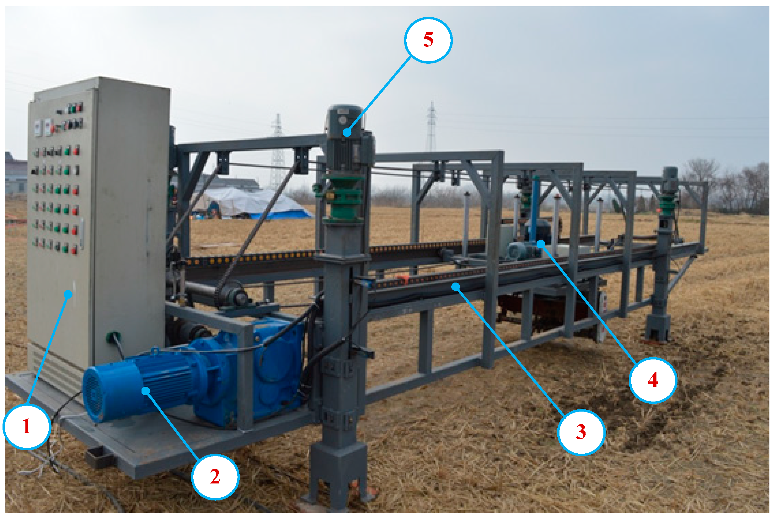
2.2. Field Experimental Method

A series of field experiments were carried out using a field in situ tillage platform (Figure 1) with four blade configurations, composed of three rotary blades (bent C, straight and hoe) (Figure 2). The four kinds of blade configurations are shown in Figure 2: a BC configuration, an SC configuration, an HC configuration, composed of a single blade, and an MC configuration composed of two straight blades and two hoe blades. All configurations were used in a field test with three rotation speeds (280, 380 and 510 rpm), with forward speed of 0.5 m/s and tillage depth of 5 cm. The test field was divided into 36 test areas. Each test area was 5 m long and 2 m wide and was subjected to one tillage test. The experiment was repeated for three times.

2.3. Evaluation Index of Field Test Research

2.3.1. Seedbed Backfill

Seedbed backfill refers to the ratio of the dry weight of soil fragmentation to the total dry weight of disturbed soil in the seedbed after tillage [17]. The greater the soil fragmentation in the seedbed, the better the backfill, the more efficient the seed–soil contact, and the more favorable the seed germination and root growth. In the test, the sand filling method was used to measure the seedbed backfill produced by different blades and rotation speeds [8]. Formula (1) for calculating the seedbed backfill is shown below:
F b = W V × ρ w
where Fb is the furrow backfill (%); W is the total dry mass of soil remaining in the furrow (kg); V is the volume of the tilled furrow (m3), and ρw is the bulk density of the soil (kg m−3).

2.3.2. Soil Fragmentation

In this paper, the Mean Weight Diameter (MWD) was used as an indicator of the soil breaking effect of the strip tillage tools [18,19,20]. The lower the MWD created by tillage, the higher the soil fragmentation degree of the machine. Formula (2) for calculating the MWD is shown below:
M W D = R = r m a x r m i n W R R
where R is the radius of the standard sieve hole; WR is the weight of soil retained on a sieve with radius R.

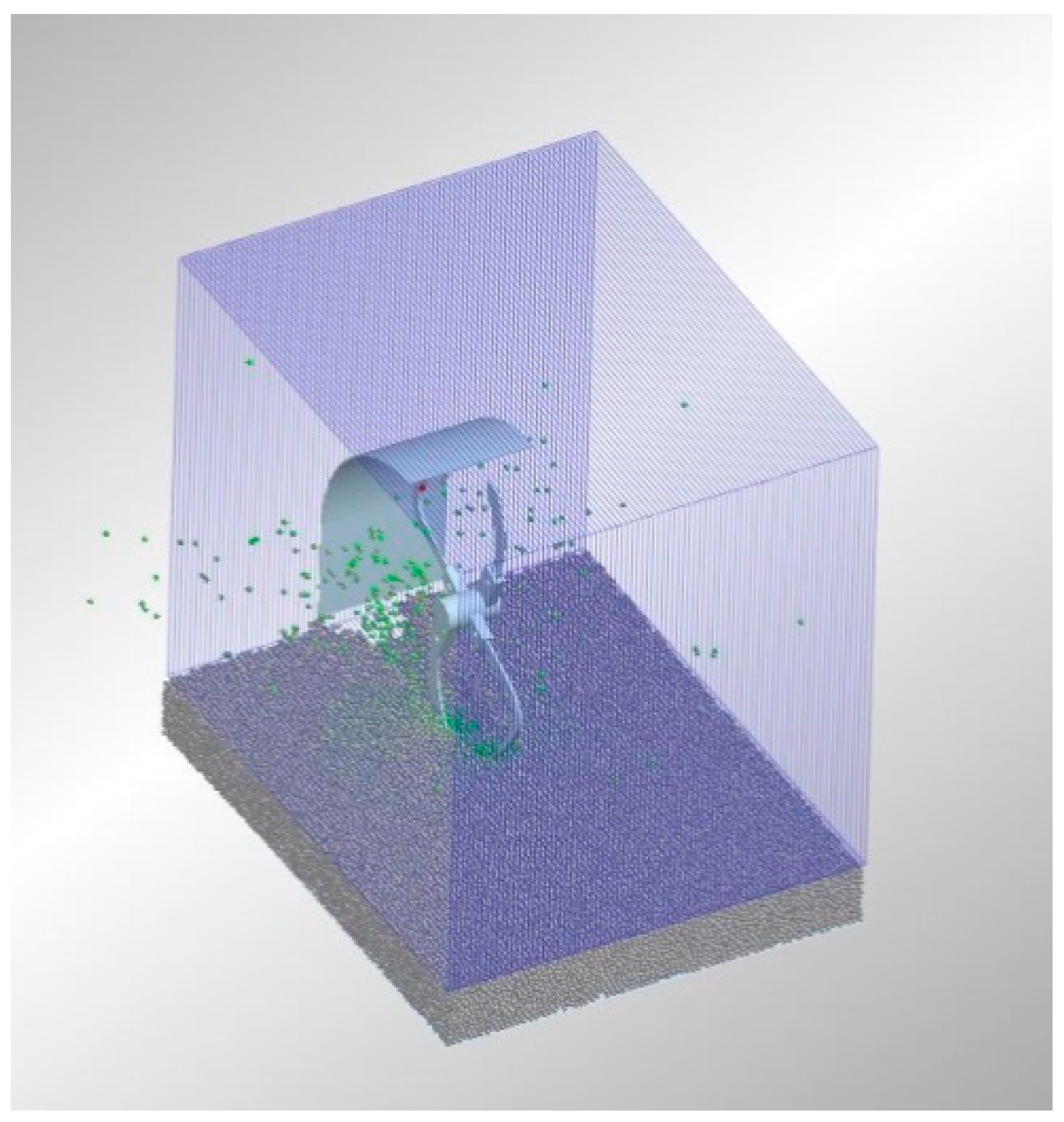
2.4. Simulation Analysis Method

The EDEM software was used as a simulation analysis tool. The shape, arrangement, rotation direction, forward speed and rotation speed of the rotary blades in the simulation were set according to the field test standard. The Hertz–Mindlin with Bonding contact model was selected to model the paddy soil according to its characteristics of high moisture content and great cohesiveness. The influence of the moisture content on the interaction between the soil particles should be fully considered when establishing a mechanical model of the contact between soil particles, especially the normal and tangential bond stress caused by the presence of moisture in the soil. Therefore, the Hertz–Mindlin with Bonding contact model was selected for soil particle modeling in this paper.
Considering the limitation of computer hardware and the rationality of calculation efficiency, the soil model parameters determined in combination with relevant data [21,22] are shown in Table 2.

2.5. Evaluation Index of Simulation Research

2.5.1. Soil Side Throwing

The soil side throwing was used to quantitatively analyze the throwing of soil particles to both sides of the seedbed by the rotary blade during the cultivation process. As shown in Figure 3, the Grid Bin Group tool in the Selection of the Analyst module of the EDEM software was used to layer the area above the soil particles surface in the simulation model, and the center line of the seedbed was used as the reference to divide the area into 80 layers every 10 mm on both sides of the seedbed. Count the number of soil particles contained in each layer and consider the ratio of the number of soil particles outside the seedbed to the total number of soil particles in the whole area as the soil side throwing rate. The higher the soil side throwing rate, the worse the seedbed backfill. The calculation was performed using Formula (3)
P = N o N a × 100 %
where P is the soil side throwing (%); No is the number of soil particles scattered outside the seedbed; Na is the total number of soil particles in the whole area.

2.5.2. Soil Particle Backfill

In the discrete element simulation, the soil particle backfill refers to the ratio of the number of soil particles in the seed bed before and after rotary blade tillage. In the Analyst module, use the Grid Bin Group function of the Selection tool to frame the seed bed area and calculate the amount of soil particles in the area before and after tillage, according to Formula (4):
P = N a N b × 100 %
where P is the soil particle backfill%; Na is the number of soil particles in the selected area after tillage; Nb is the number of soil particles in the selected area before tillage.

3. Results

3.1. Analysis of the Interaction between Rotary Blade and Soil

In Figure 4, Figure 5, Figure 6 and Figure 7, it can be seen that the cultivation process of a rotary blade is mainly divided into three stages. The first stage is soil cutting, where the blade cuts into the soil. The second stage is the joint movement of blade and soil. The cut soil is attached to the rotary blade and moves with the blade. The third stage is the soil throwing stage. The blade throws out the soil, and the soil fragments are completely separated from the blade. From the above, it can be seen that the soil throwing stage is the key component affecting soil crushing and backfill. The soil fragments are thrown out by the rotary blade and collide with the soil-retaining plate, causing secondary crushing. One part of the soil fragments falls back to the seedbed, while the other part of the soil fragments is thrown to both sides of the seed bed. The BC and HC configurations caused obvious scattering of the soil fragments, and only a small amount of soil fragments were thrown out in the throwing stage with the SC configuration. During the cultivation process with the MC configuration, straight blades and hoe blades alternate. The straight blades installed on both sides mainly control the boundary of the seedbed and do not scatter the soil fragments. The hoe blades installed in the middle of the rotary tool crush the soil, so the scattering of the soil fragments is not obvious.

3.2. Soil Side Throwing

It can be seen in Figure 8, Figure 9, Figure 10, Figure 11 and Figure 12 that the soil side throwing during tillage is significantly affected by the rotation speed, and an increase in the rotation speed leads to an increase in the amount of soil fragments thrown to both sides of the seedbed. This is because an increase in the rotation speed leads to an increase of the kinetic energy of the soil fragments, and the increase in the intensity of the collision between the soil and the retaining plate leads to an increase in the lateral movement of the soil fragments, and the diffusion range of the soil fragments increases with the increase in the rotation speed. The soil side throwing in the BC and HC configurations was significantly higher than that in the SC configuration. When the rotation speed was 510 rpm, the soil side throwing in the BC and HC configurations was as high as 92% and 85%, while the soil side throwing in the SC configuration was only 70%. This is because most of the soil fragments thrown out in the BC and HC configurations in the process of cultivation were scattered to both sides of the seedbed after collision with the retaining plate (Figure 5 and Figure 6). The straight blade in the SC configuration had no cross-cutting edge and could not side-throw the soil (Figure 4). The soil fragments formed in the process of cultivation had the smallest diffusion range and were mainly concentrated in the seedbed, so the resulting soil side throwing was the less extensive.
It can be seen from the cultivation process in MC configuration that the straight blades installed on both sides cut into the soil before the hoe blades installed in the middle. The high-speed alternative cultivation process of the straight blades on both sides is similar to that of the soil-retaining disc mentioned in the study of Lee et al. The soil side throwing in MC configuration was only 70% of that in HC configuration when the rotation speed was 510 rpm.

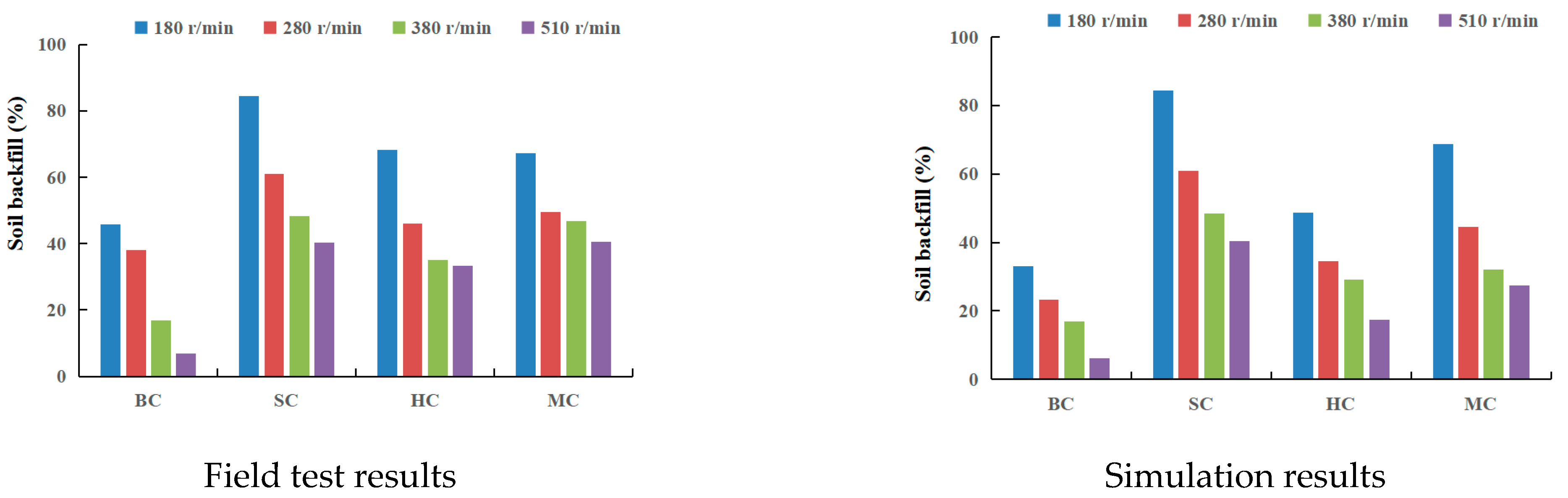
3.3. Seedbed Backfill

The purpose of cultivation is to create a loose and moist soil environment. There should be enough soil fragments in the seedbed to ensure seed germination, crop root growth and air moisture [23]. Therefore, the seedbed backfill is an important evaluation index to evaluate the working quality of the wheat rotary strip–till planter. From the simulation and field test results (Figure 13), it can be seen that the backfill created by different tillage blades was quite different and decreased with the increase in the rotation speed, especially the backfill produced in the BC configuration. The backfill produced when the rotation speed was 510 rpm was less than 10%. This is because the bent C blade in the BC configuration had a wide cross-cutting edge, and the soil-throwing phenomenon was obvious (Figure 5). After the impact of the soil fragments with the retaining plate, the soil fragments diverged to both sides of the seedbed, obviously. During the cultivation process in HC configuration, the blade was inserted into the soil first, and then the broken soil was picked up. During this process, some of the broken soil moved towards the forward direction of the machine, and a small part was thrown out laterally (Figure 6 and Figure 9). Therefore, when the rotation speed was 510 rpm, the soil backfill rate could still reach 36%, which was much higher than that reached in the BC configuration. The straight blade in the SC configuration had no bending part and no soil throwing characteristics (Figure 4) and could effectively prevent the lateral movement of the soil fragments during the cultivation process [17]. Therefore, the backfill was still higher than 40% when the rotation speed was 510 rpm. The straight blades installed on both sides in the MC configuration could effectively prevent the movement of the soil fragments to both sides of the seed bed during the cultivation process, so the soil backfill generated in the MC configuration was significantly higher than that in the BC and HC configurations. When the rotation speed was 510 rpm, the soil backfill could still reach 40%, and the loose and moist soil in the seed bed could allow seed germination.

3.4. Soil Fragmentation

The test results in Figure 14 show that the rotation speed was the main factor affecting the soil fragmentation, which is consistent with the research results of Matin et al. [24], Lee et al. [25], Kheiralla et al. [26], ASL et al. [27], Chertkiatipol et al. [28] and Upadhyay et al. [29]. The increase in the rotation speed caused the soil block cut by the blade in the soil cutting stage to become smaller, and the kinetic energy obtained by the thrown soil fragments increased, which increased the degree of secondary breaking caused by the collision between the soil and the retaining plate after the soil was thrown out. Therefore, soil fragmentation increased with the increase in the rotation speed. The fragmentation produced in the SC configuration was significantly lower than that in the other three configurations, because the straight blade in the SC configuration could not efficiently throw the soil. In the process of farming, the soil is broken only by its interaction with the blade; a paddy soil is characterized by wet viscosity, so the force exerted by the straight blade was not enough to produce a good soil fragmentation. Therefore, when the rotation speed was 510 r/min, the MWD was still greater than 30 mm and could not allow sowing. At the same rotation speed, the soil fragmentation in the MC configuration did not decrease due to the reduction of the number of hoe blades. This is because the straight blade in the MC configuration released the soil boundary constraint on one side of the seedbed during the cultivation process, making the soil crushing by the hoe blade installed in the middle easier. This design effectively solves the problem of the significant increase in tillage energy consumption caused by the addition of a retaining disc, as shown in the study of Lee et al. [25]. In view of this, the MC configuration is more suitable to be used with a tillage tool such as the wheat rotary strip–till planter in the presence of a paddy soil.

4. Discussion

At the same travel speed, the soil cutting intercept will decrease with the increase in the rotation speed. Therefore, as shown in Figure 14, the soil crushing effect of the four blade configurations increased with the increase in the rotation speed. This phenomenon can be explained by two mechanisms. One is that the soil fragments produced by a small soil cutting intercept are naturally small; second, the increase in the rotation speed increases the kinetic energy of the soil fragments moving with the blade, the impact between the soil fragments and the shield is more violent, the secondary crushing effect of the fragments is stronger, and the resulting soil fragments are smaller. With the help of a high kinetic energy, the soil fragments thrown at both sides of the seedbed will be thrown farther away. Some soil will also be scattered at both sides of the seedbed after a strong impact with the shield. Therefore, the increase in the rotation speed will also reduce the soil backfill (Figure 13). This conclusion is been consistent with the research results of Lee et al. [25] and Matin et al. [17].
The process of cutting and breaking of soil in the field could not be directly observed due to the influence of factors such as the high rotation speed and the complex field test environment. EDEM simulation analysis allowed understanding the actions of the different blade configurations. The tangential edge of the bent C blade in the BC configuration was wide, so it could hold the soil fragments and forcefully throw them on the shield. Therefore, most of the soil fragments were scattered on both sides of the seedbed after hitting the shield (Figure 4). Only a small number of soil fragments fell back into the seedbed after the impact. With the increase in the rotation speed, fewer soil fragments returned to the seedbed; therefore, the higher the rotation speed, the worse the backfill (Figure 13).
The straight blade in the SC configuration had no tangent blade, so it was unable to lift the soil and throw it to the retaining plate to produce secondary crushing (Figure 5). The friction between the soil and the cutting edge of the straight blade was the main source of soil fragmentation during the cultivation process; therefore, its crushing effect was the worst. When the rotation speed was 510 rpm, the mean weight diameter (MWD) of the soil fragments produced in the SC configuration was still more than 35 mm (Figure 14). However, due to the fact that the straight blade did not have good throwing characteristics, most of the cut soil fragments were left in the seedbed, producing the best soil backfill (Figure 9).
The EDEM simulation analysis evaluated the cultivation process using the hoe blade in the HC configuration. The cultivation process with the hoe blade mainly consists of two stages: one involves the insertion of the blade tip into the soil, and the other consists in collecting the soil to produce the first crushing (Figure 6). The tangential edge of the hoe blade was too small to hold the soil fragments, causing some soil fragments to spread to both sides of the seedbed without impacting the shield, which reduced the soil backfill (Figure 13). The MC configuration provided an improved soil backfill with respect to the BC configuration and a reduced mean weight diameter (MWD) than the SC configuration.
In the MC configuration, the hoe blade mainly allowed soil fragmentation. The soil thrown by the hoe blade to both sides of the seeded would be blocked by the straight blades; therefore, the soil backfill produced by the MC configuration was better than that produced by the hoe blade (Figure 13). In addition, the straight blades first broke the cohesive force of the soil on both sides of the seedbed wall during the cultivation process, making it easier for the hoe blade to fragment the soil. Under the joint action of the straight blades and the hoe blades, the soil breaking effect in the MC configuration was not reduced by the reduction in the number of the hoe blades (Figure 14). During the high-speed rotation of the rotary blade, the straight blades installed on both sides of the MC configuration were just like the soil-cutting discs proposed by Lee et al. [25], which could effectively prevent the soil fragments from being thrown onto both sides of the seedbed. However, because the straight blades moved alternately and were only two, the energy consumption of cultivation was far lower than that of the soil-cutting discs used by Lee et al. [25], leading to a more optimized design.
Considering the reduced soil side throwing, better soil backfill, and higher soil fragmentation, the field test and simulation data showed that the MC configuration is an optimal design in the presence of paddy soil conditions and it is recommended when using tillage tools such as the strip tillage planter.

5. Conclusions

The mechanism of tool–soil interaction was theoretically analyzed at the micro and macro levels by using a discrete element simulation and field experiments. The results of four blade configurations operating at three speeds of a rotary tiller operating in a wet paddy soil demonstrated that the BC configuration could produce a fine soil fragmentation, but too many soil fragments were thrown out of the seedbed to form a good backfill; especially when the rotation speed was greater than 380 rpm, there were few soil fragments in the seedbed to meet the sowing demands. The SC configuration could form a good backfill, but the soil fragments were too large, even when the rotation speed was 510 r/min. The hoe blade in the HC configuration had a good soil-breaking performance, and during the cultivation process, the blade threw part of the soil fragments in the direction of the machine, so the soil backfill and fragmentation were better than in the BC and SC configurations; however it was still inferior compared to the MC configuration.
This study recommends the MC configuration for the strip tillage planter. The hoe blade in MC configuration ensures the performance of soil fragmentation with its good tillage characteristics. The straight blade can effectively prevent the scattering of soil fragments to both sides of the seedbed and significantly improves the soil backfill at high rotation speeds. Compared with other blade configurations, the MC configuration offers significant advantages, improving the tillage quality in cohesive paddy soil.

Author Contributions

Conceptualization, Y.Y. and Z.H.; methodology, Y.Y. and Q.D.; investigation, F.G.; writing—original draft preparation, Y.Y. and F.G.; writing—review and editing, Y.Y., Z.H., F.G. and Q.D. All authors have read and agreed to the published version of the manuscript.

Funding

This research was funded by the Natural Science Foundation of Jiangsu province (Grant No. BK 20221187).

Institutional Review Board Statement

Not applicable.

Informed Consent Statement

Not applicable.

Data Availability Statement

Not applicable.

Conflicts of Interest

The authors declare no conflict of interest.

References

  1. Yanshan, Y.; Qishuo, D.; Tingfeng, H.; Cuihua, S.; Feng, W. Research of the tillage mechanism for wheat rotary strip-till planter. J. Chin. Agric. Mech. 2021, 6, 10–16. (In Chinese) [Google Scholar]
  2. Wei, G.; Jian, S.C.; Fang, H.M.; Peng, Q.J.; Niu, M.M. Current situation prospect of conservation tillage technology in dry-farming areas of North China. J. Chin. Agric. Mech. 2019, 3, 7–10. (In Chinese) [Google Scholar]
  3. Yang, Y.; Hu, Z.; Gu, F.; Wang, J.; Ding, Q. Effects of Tillage Methods on Crop Root Growth Trend Based on 3D Modeling Technology. Agriculture 2022, 12, 1411. [Google Scholar] [CrossRef]
  4. Kumar, N.; Chaudhary, A.; Ahlawat, O.P.; Naorem, A.; Upadhyay, G.; Chhokar, R.S. Crop residue management challenges, opportunities and way forward for sustainable food-energy security in India: A review. Soil Tillage Res. 2023, 228, 105641. [Google Scholar] [CrossRef]
  5. Wang, C.; Li, H.; He, J.; Wang, Q.; Lu, C.; Yang, H. Optimization Design of a Pneumatic Wheat-Shooting Device Based on Numerical Simulation and Field Test in Rice–Wheat Rotation Areas. Agriculture 2022, 12, 56. [Google Scholar] [CrossRef]
  6. Huo, L.; Liu, J.; Abbas, A.; Ding, Q.; Wang, H.; Zhou, Z.; Meng, L.; Bai, Z. Effects of dry bulk density and water content on compressive characteristics of wet clayey paddy soil. Agron. J. 2022, 114, 2598–2607. [Google Scholar] [CrossRef]
  7. Jianjun, H.; Haijie, Y.; Jianguo, Z. Design and test of wedge drag reduction rotary blade. Trans. CSAE 2019, 8, 55–64. (In Chinese) [Google Scholar]
  8. Matin, M.A.; Hossain, M.I.; Gathala, M.K.; Timsina, J.; Krupnik, T.J. Optimal design and setting of rotary strip-tiller blades to intensify dry season cropping in Asian wet clay soil conditions. Soil Tillage Res. 2020, 207, 104854. [Google Scholar] [CrossRef]
  9. Yang, Y.; Fielke, J.; Ding, Q.; Re, H. Field experimental study on optimal design of the rotary strip-till tools applied in rice-wheat rotation cropping system. Int. J. Agric. Biol. Eng. 2018, 11, 88–94. [Google Scholar] [CrossRef] [Green Version]
  10. Chong, Z.; Xuhui, F.; Mingsen, L.; Guang, L.; Chunkai, Z.; Wenliang, S. Simulation Analysis and Experiment of Soil Disturbance by Chisel Plow Based on EDEM. Trans. Chin. Soc. Agric. Eng. 2022, 2, 52–59. (In Chinese) [Google Scholar]
  11. Hunt, S.P.; Meyers, A.G.; Louchnikov, V. Modelling the Kaiser effect and deformation rate analysis in sandstone using the discrete element method. Comput. Geotech. 2003, 7, 611–621. [Google Scholar] [CrossRef]
  12. Djordjevic, N. Discrete element modelling of the influence of lifters on power draw of tumbling mills. Miner. Eng. 2003, 16, 331–336. [Google Scholar] [CrossRef]
  13. Wang, C.; Tannant, D.D.; Lilly, P.A. Numerical analysis of the stability of heavily jointed rock slopes using PFC2D. Int. J. Rock Mech. Min. Sci. 2003, 3, 415–424. [Google Scholar] [CrossRef]
  14. Maohua, X.; Kaixin, W.; Wang, Y.; Weichen, W.; Feng, J. Design and Experiment of Bionic Rotary Blade Based on Claw Toe of Gryllotalpa orientalis Burmeister. Trans. Chin. Soc. Agric. Eng. 2021, 2, 55–63. (In Chinese) [Google Scholar]
  15. Huimin, F.; Changying, J.; Tagar, A.A.; Qingyi, Z.; Jun, G. Simulation analysis of straw movement in straw-soil-rotary blade system. Trans. Chin. Soc. Agric. Eng. 2016, 1, 60–67. (In Chinese) [Google Scholar]
  16. Huimin, F.; Changying, J.; Tagar, A.; Qingyi, Z.; Jun, G.; Arslan, C. Analysis of soil dynamic behavior during rotary tillage based on distinct element method. Trans. Chin. Soc. Agric. Eng. 2016, 3, 22–28. (In Chinese) [Google Scholar]
  17. Matin, M.A.; Fielke, J.M.; Desbiolles, J. Furrow parameters in rotary strip-tillage: Effect of blade geometry and rotation speed. Biosyst. Eng. 2014, 118, 7–15. [Google Scholar] [CrossRef]
  18. Dexter, A.R.; Birkas, M. Prediction of the soil structures produced by tillage. Soil Tillage Res. 2004, 2, 233–238. [Google Scholar] [CrossRef]
  19. Arvidsson, J.; Hillerström, O. Specific draught, soil fragmentation and straw incorporation for different tine and share types. Soil Tillage Res. 2010, 1, 154–160. [Google Scholar] [CrossRef]
  20. Caruso, T.; Barto, E.K.; Siddiky, M.R.K. Are power laws that estimate fractal dimension a good descriptor of soil structure and its link to soil biological properties? Soil Biol. Biochem. 2011, 2, 359–366. [Google Scholar] [CrossRef]
  21. Zheng, K.; He, J.; Li, H. XIP Research on polyline soil-breaking blade subsoiler based on subsoiling soil model using discrete element method. Trans. Chin. Soc. Agric. Eng. 2016, 9, 62–72. (In Chinese) [Google Scholar]
  22. Deng, J.; Hu, J.; Li, Q.; Yu, T. Simulation and experimental study on the subsoiler based on EDEM discrete element method. J. Chin. Agric. Mech. 2016, 4, 14–18. (In Chinese) [Google Scholar]
  23. Solhjou, A.; Desbiolles, J.; Fielke, J.M. Soil translocation by narrow openers with various blade face geometries. Biosyst. Eng. 2013, 3, 259–266. [Google Scholar] [CrossRef]
  24. Matin, M.A.; Fielke, J.M.; Desbiolles, J.M.A. Torque and energy characteristics for strip-tillage cultivation when cutting furrows using three designs of rotary blade. Biosyst. Eng. 2015, 129, 329–340. [Google Scholar] [CrossRef]
  25. Lee, K.S.; Park, S.H.; Park, W.Y. Strip tillage characteristics of rotary tiller blades for use in a dryland direct rice seeder. Soil Tillage Res. 2003, 1, 25–32. [Google Scholar] [CrossRef]
  26. Kheiralla, A.F.; Yahya, A.; Zohadie, M. Modelling of power and energy requirements for tillage implements operating in Serdang sandy clay loam, Malaysia. Soil Tillage Res. 2004, 1, 21–34. [Google Scholar] [CrossRef]
  27. Asl, J.H.; Singh, S. Optimization and evaluation of rotary tiller blades: Computer solution of mathematical relations. Soil Tillage Res. 2009, 1, 1–7. [Google Scholar] [CrossRef]
  28. Chertkiattipol, S.; Niyamapa, T. Variations of Torque and Specific Tilling Energy for Different Rotary Blades. Int. Agric. Eng. J. 2011, 3, 1–14. [Google Scholar]
  29. Upadhyay, G.; Raheman, H. Comparative assessment of energy requirement and tillage effectiveness of combined (active-passive) and conventional offset disc harrows. Biosyst. Eng. 2020, 198, 266–279. [Google Scholar] [CrossRef]
Figure 1. Image of the in situ experimental platform. 1 Control box, 2 drive motor, 3 lifting guide rail, 4 tillage platform, 5 lifting motor.
Agriculture 13 00632 g001
Figure 2. Tillage blade and configuration.
Agriculture 13 00632 g002
Figure 3. Hierarchical processing of the simulation models.
Agriculture 13 00632 g003
Figure 4. Sketch of the tillage process in the BC configuration at 280 rpm. (a) cuting into soil, (b) moving together, (c) throwing out soil.
Agriculture 13 00632 g004
Figure 5. Sketch of the tillage process in the SC configuration at 280 rpm. (a) cuting into soil, (b) moving together, (c) throwing out soil.
Agriculture 13 00632 g005
Figure 6. Sketch of the tillage process in the HC configuration at 280 rpm. (a) cuting into soil, (b) moving together, (c) throwing out soil.
Agriculture 13 00632 g006
Figure 7. Sketch of the tillage process in the MC configuration at 280 rpm. (a) Straight blade cuting into soil, (b) Hoe blade cuting into soil, (c) throwing out soil.
Agriculture 13 00632 g007
Figure 8. Soil side throwing in the BC configuration at different rotation speeds.
Agriculture 13 00632 g008
Figure 9. Soil side throwing in the SC configuration at different rotation speeds.
Agriculture 13 00632 g009
Figure 10. Soil side throwing in the HC configuration at different rotation speeds.
Agriculture 13 00632 g010
Figure 11. Soil side throwing in the MC configuration at different rotation speeds.
Agriculture 13 00632 g011
Figure 12. Effect of blade geometry and rotation speed on soil side throwing.
Agriculture 13 00632 g012
Figure 13. Effect of blade configuration and rotation speed on soil backfill.
Agriculture 13 00632 g013
Figure 14. Effects of blade configuration and rotation speed on MWD.
Agriculture 13 00632 g014
Table 1. Soil physical parameters in the test area.
Depth
(cm)
Water Content
(%)
Dry Bulk Density
(kg m−3)
Cohesion
(kPa)
Internal Friction Angle
(°)
Cone Index
(kPa)
Plastic Limit
(%)
Field Capacity
(%)
0–1031.80.12530.9113.158725.240.6
Table 2. Properties of the simulation model.
ParameterValue
Length, width and height of soil model(mm)1000 × 800 × 80
Soil density (Kg·m−3)1280
Poisson’s ratio of soil0.38
Shear modulus of soil (Pa)6 × 10⁷
Soil–soil recovery coefficient0.6
Soil–soil static friction coefficient0.6
Soil–soil dynamic friction coefficient0.5
Soil particle radius (mm)5
Soil bond stiffness (N·m−3)1 × 10⁶
Critical bond stress of the soil (Pa)3 × 10⁵
Soil bonding radius (mm)6
Disclaimer/Publisher’s Note: The statements, opinions and data contained in all publications are solely those of the individual author(s) and contributor(s) and not of MDPI and/or the editor(s). MDPI and/or the editor(s) disclaim responsibility for any injury to people or property resulting from any ideas, methods, instructions or products referred to in the content.

