Article

Development of Boom Posture Adjustment and Control System for Wide Spray Boom

1
College of Agricultural Engineering, Jiangsu University, Zhenjiang 212013, China
2
Key Laboratory of Modern Agricultural Equipment and Technology, Ministry of Education, Zhenjiang 212013, China
*
Author to whom correspondence should be addressed.
Agriculture 2023, 13(11), 2162; https://doi.org/10.3390/agriculture13112162
Submission received: 7 September 2023 / Revised: 9 November 2023 / Accepted: 11 November 2023 / Published: 17 November 2023

Abstract

:
To obtain a more consistent droplet distribution and reduce spray drift, it is necessary to keep the entire spray boom parallel to the crop canopy or ground and maintain a certain distance from the spray nozzles to the crop canopy or ground. A high-performance boom active control system was developed for boom trapezoid suspension. The hydraulic system and hardware circuit of the boom control system were designed based on analyzing the configuration of active trapezoid suspension. The mathematical models of valve-controlled hydraulic cylinders and active boom suspensions were developed. Step response and frequency domain response analysis of passive suspension were conducted by Simulink simulations, and then key parameters of the boom suspension and hydraulic system were determined. A feedforward proportion integration differentiation (FPID) control algorithm was proposed to improve the tracking performance. The designed control system was assembled on a 24 m boom with trapezoid suspension. The response characteristic of the active boom control system was tested by the step signal and the sinusoidal signal from a six-degree-of-freedom hydraulic motion platform. Firstly, the tracking performance of the active balance control system for the PID (proportion integration differentiation) and FPID control algorithms was compared for a given 0.2 Hz sine signal. Then, for the ground-following control system, the response characteristics in challenging terrain and tracking performance in less challenging terrain were tested. Field experiment results indicate that the maximum rolling angle of the chassis was 3.896 ° while the maximum inclination angle of the boom was 0.453 ° . The results show that the designed boom adjustment and control system can effectively adjust the boom motion in real time and meet the requirements of field operation.

1. Introduction

The rapid development of land transfer in China promoted the emergence of large and medium-sized farms. A variety of large agricultural machinery with high operation efficiency is widely used in the agricultural industry. Due to advantages such as wide operation spraying swath, precise quantification of spraying, and uniform spraying amount, sprayers with above 24 m spraying swath are widely used in field crop protection. However, the large flexibility of the boom was caused by the wide spray boom. Since the ground surface is undulating in the field, the small vibration of the sprayer body will cause a large fluctuation of boom ends. The unexpected boom movements frequently happen as the sprayer travels over bumpy ground or undulating fields. This not only affects the uniformity of spray quantity distribution but also leads to a decline in application quality [1]. In severe cases, the boom ends will touch the ground or crop canopy, causing damage to the boom and sprayer and injury to the crop. To ensure working quality and safety, the driver of the sprayer should observe whether there is contact between the boom and the crop during the operation and thus adjust the tilt angle of the boom manually, which increases the labor intensity of the driver.
The vertical rolling motion has a significant effect on spray distribution pattern [2,3] and droplet spray uniformity [4,5,6]. To obtain a more consistent droplet distribution and reduce spray drift, it is necessary to keep the spray boom parallel to the crop canopy or ground and maintain a certain distance from the spray nozzle tips to the crop canopy or ground. Unfortunately, the passive suspensions hardly always make boom maintain parallel with the crop canopy or ground due to the deflection of the vehicle tires and sinkage of the wheels into the ground. To make up for the deficiency of passive suspension, a variety of active suspensions were investigated [7,8,9,10,11,12,13,14,15].
Different control strategies, such as proportional-integral (PI), optimal control [16], state feedback [17], sliding mode control [18], and H∞ theory [19], were used to adjust the boom motions in the vertical and horizontal planes. To improve the response ability and tracking performance of the active boom suspension, the FPID (feedforward proportion integration differentiation) control algorithm is proposed by integrating the forward control link with the PID. As an open-loop control, the forward feedback control can directly exert the correction effect according to the disturbance quantity when the disturbance occurs. In theory, feedforward control can eliminate the deviation caused by disturbance. At present, feedforward control is widely used in electro-hydraulic servo systems and hydraulic systems. The velocity feedforward compensation proportional integral control (VFPID) was used to control the active pendulum boom suspension and effectively control the boom movement [13]. However, the forward feedback relies on a precise system model to eliminate the deviation caused by disturbance. Therefore, the mathematical model of the boom chassis was established to obtain rapid response performance.
Several automatic control devices were developed for spraying height control by manufacturers such as Muller, Norca, and Ravel. Satisfactory control performance was obtained in flat, large plains when the boom sprayer travels across the field at relatively low speed. However, few imported spray height controllers have been used by domestic sprayers. The main reasons were as follows: (1) The control performance was discounted when these sprayers passed over challenging terrain, such as hilly and mountainous cultivated land, so that the boom hardly kept the desired spraying height at the desired response speed. Unfortunately, most of the cultivated fields are situated in hilly and mountainous areas of China. It is necessary that the high response speed of the electro-hydraulic servo system built in active boom suspension be required to meet the challenge of the complex environment; (2) it is difficult to match these imported control devices with special requirements for machine structure and hydraulic-servo system design with boom sprayers made in China; (3) these imported control devices were expensive, and the farmers could not afford to use them. The UF02 mounted spray from Amazone and Albators from Lennken are more than 90,000 pounds; (4) The control strategy assembled in these devices was private so that the manufacturer’s technicians are required to repair it in the event of a failure, which results in increased maintenance costs and non-working time of the sprayers.
Based on the above reasons, although most large-sized sprayers are equipped with boom suspension, only a few controllers [13] whose control performance needed to be further improved were developed by manufacturers.
To reduce costs and improve response performance in challenging environments, many different attempts were made. A high-performance boom control system for pendulum active suspension was designed based on a DSP microprocessor and velocity feedforward compensation proportional integral control algorithm [14], which can realize effective control for the boom movement and meet the requirements of field use in less challenging terrains. Although the proposed control system provided theory and references for relative research, its performance can be further improved by developing an accurate system model.
The AMAZONE ContourControl device was assembled on the UF2002-mounted sprayer, which could realize fully automatic boom guidance, including boom height, tilt adjustment, and boom lifting on the headland. This allowed the boom to maintain an optimal distance to the target surface across the whole working swath, even on extremely hilly terrain [20]. The boom height and boom angling of the LEMKEN Primus trailed sprayer were easily adjusted by the advanced hydraulic control system, and the boom damage was avoided by the advanced Magneo balance adjustment mechanism [21]. However, these two sprayers were tested in a cotton field in Xinjiang, where there are unforeseeable dark pits to lose to 1 m in the cotton fields. The test results indicated the response speed of the electro-hydraulic servo system built in these two kinds of active boom suspension was discounted, resulting in frequent damage to the boom. The main reason was that the response speed of the electro-hydraulic servo system was not fast enough for the challenging terrain. In this study, to acquire high response performance, sensing one-way valves, high-speed proportional valves, and hydraulic cylinders were used in the design of the hydraulic servo system. Furthermore, the FPID control algorithm was proposed, which was able to eliminate disturbances before the controlled quantity variable occurred.
The object of this study is to develop an automatic control device with low-cost and high-response spaying height for trapezoidal active suspension, aiming to maintain the desired spraying height from the crop canopy or ground in challenging terrain. The detailed aims include: (1) realize the automatic balance of boom in flat terrains; (2) ensure boom automatic following with crop canopy or ground in sloping and undulating terrains with rapid response; (3) realize the quick raise of boom wing in challenging emergency circumstances such as unilateral tire of sprayer sinkage into the ground quickly and avoid damage because of touching between boom tip and ground.

2. Materials and Methods

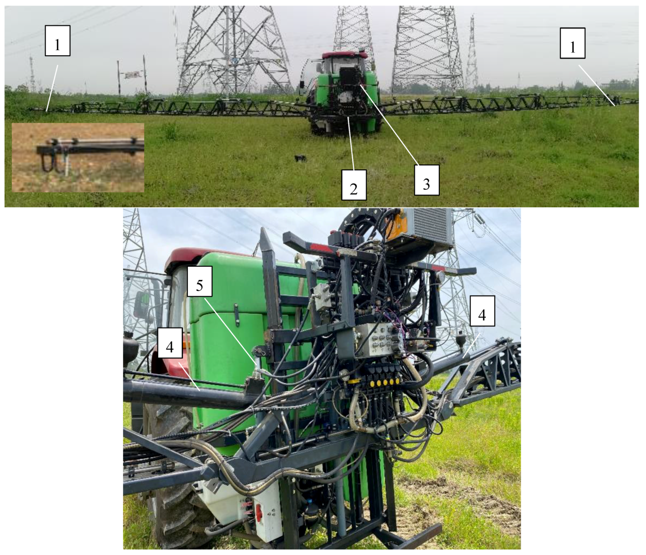
2.1. Total Configuration of Active Trapezoid Suspension

The schematic diagram of active trapezoid suspension is shown in Figure 1.
The boom sprayer is mounted to the tractor by a three-point suspension mechanism, and the boom is attached to the sprayer via the boom chassis. The entire boom is divided into the left arm on the left side, the right arm on the right side, and the central frame situated in the middle part. The bottom of the left and right arms is hinged to the center frame, and the top parts of the left and right arms are articulated to the counterparts of the middle frame by the imitating hydraulic cylinder 14 or cylinder 15, respectively. Under the action of the following cylinders, the left arm and/or right arm can be revolved through the revolute joints to make unilateral or two-side boom arms that keep parallel to the ground or crop canopy. The boom lifting mechanism is comprised of a lifting hydraulic cylinder, lifting frame, fixed pulley, steel rope around the pulley, and a V-shape guide rail on the boom suspension frame, which is used to adjust the height of the entire boom. The mechanical limit device and polyurethane dampers are adopted to suppress the horizontal movements forward and backward and absorb the shock of the horizontal load. The two ends of the steel rope are fixed to the center frame. One end of the lifting hydraulic cylinder is welded to the boom suspension, and the other end is attached to the fixed pulley. As the lifting hydraulic cylinder retracts (extends), the whole boom ascends (descends). The boom suspension is used to bear the weight of the boom and the inertial load. The ends of balance hydraulic cylinder 2 and hydraulic cylinder 7 are jointed to the boom and boom lifting frame by revolute joints, respectively. The center frame rotates in a counterclockwise direction while the balance hydraulic cylinder 2 retracts (extends) and the balance hydraulic cylinder 7 extends (retracts). The maximum rolling angle of the boom relative to the chassis is determined by the mechanical limit device. Three ultrasonic sensors are adopted to sense the distance between the boom and the ground/crop canopy. Two inclination angle sensors (3 and 10) are mounted on the boom chassis and the center boom, which are used to collect the inclination angles of the boom chassis and the center boom, respectively.

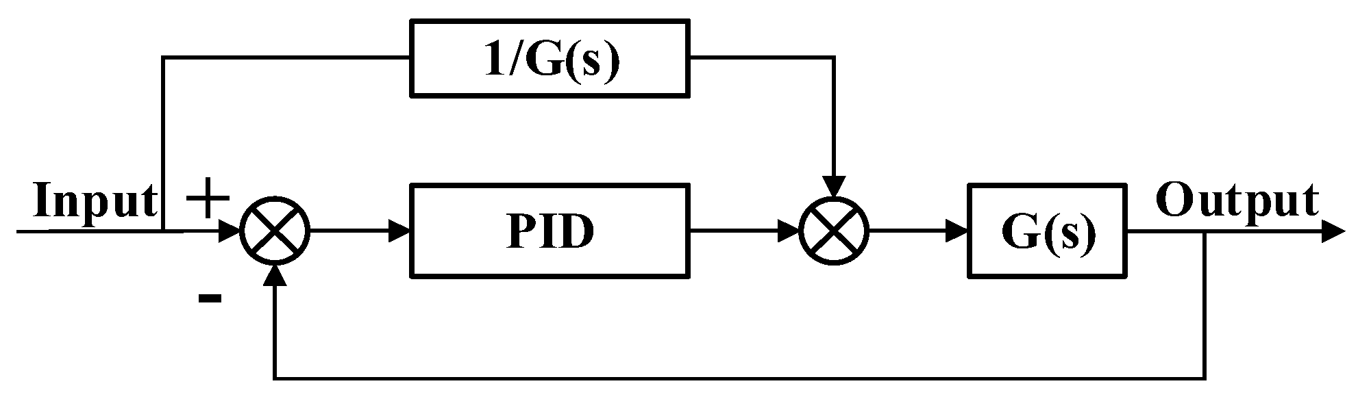
2.2. Design of a Hydraulic System

Figure 2 shows the schematic diagram of the hydraulic system, which is composed of an active balance hydraulic circuit, ground imitation circuit, lifting hydraulic circuit of entire boom suspension, and oil supply circuit.
Five cylinders, which are controlled by four three-position, four-way proportional valves, are adapted to control the boom attitude. Cylinders 8 and 9, which are controlled by valve 13, are used to keep the boom parallel to the ground or crop canopy. Under the action valve 13, the piston rod of cylinder 8 extends (retracts) and that of cylinder 9 retracts (extends), thus the whole boom is slanted to left or right and the boom balance is realized. Cylinders 25 and 26, which are controlled by valves 21 and 22, respectively, are adapted to rotate the left-side boom arm and right-side boom arm, respectively. Cylinders 25 and 26 can work along or together. Under the action of valve 21, the left-side boom arm is lifted (lowered) when the piston rod of cylinder 25 extends (retracts). The cylinder 16 is applied to adjust the height of the whole boom suspension, which is a one-way cylinder and controlled by proportional valve 20. The boom suspension is lifted when the piston rod extends. The lowering movement is accomplished by the gravity of the boom. Thus, the lifting and lowering of the whole spray boom is achieved. The balance valve 19 plays the role of locking the hydraulic oil road. The hydraulic system unloads, and the piston rod of the cylinder stops moving so that the boom keeps the current fixed. The overflow valves 3 and 5, pressure compensator 14, and sensing one-way valve 15 are used to maintain the pressure stability of the hydraulic pipelines.

2.3. Hardware Circuit of the Boom Control System

The hardware circuit of the boom control system is shown in Figure 3. To meet the real-time requirement of the control system and ensure system stability, the high-quality embedded industrial control module EMB8610I (Zhong Qian Ling Yun Electronic Co., Ltd., Beijing, China), whose MCU STM32F107VCT6 (STMicroelectronics, Co., Ltd., Agrate Brianza, Italy) was 32-bit ARM Cortex-M3 processor with 72 MHz main frequency was selected as the controller. Moreover, EMB8610I integrated two RS-232, one RS-485, one CAN, one TTL Uart communication interface, two pulse-width modulation (PWM) output channels, seventeen 12-bit analog voltage/current input channels with a range of 0–10 V or 0–20 mA (switching voltage or current mode by jumper), and two 12-bit analog voltage output channels with a range of 0–10 V or 0–5 V (selecting by jumper).
The output signal of the ultrasonic sensor is an analog quantity in the range of 0–20 mA, so that three ultrasonic sensors can be connected directly to an analog voltage/current input channel. Similarly, the dynamic inclination angle sensor with digital output signals was attached to the controller by the RS-232 interface. The touch screen (DC10600M070_2111_0C, Dacai Optoelectric Co., Ltd., Guangzhou, China) with two RS-232 serial interfaces was adapted to set control parameters, transmit control commands, display the running state, and store sensor data for the control system. The communication between the touch screen and the controller was achieved by the RS-232 serial interface.
Three ultrasonic ranging sensors UC2000-30GM-IUR2-V15 (Pepperl+Fuchs, Co., Ltd., Bühl, Germany) were adopted as sensing the relative distance between the sprayer boom and crop canopy or ground. Digital drivers control the current to the solenoid of Atos proportional valves without a transducer, according to the electronic reference input signal. One E-BM-AS driver can drive two single or one double solenoid proportional valve. The solenoid proportionally transforms the current into a force, acting on the valve spool or poppet against a reacting spring, thus providing hydraulic regulation. The input voltage ranges from −10 V to +10 V. To achieve voltage matching, the linear conversion from D/A output voltage 0 V to 10 V to the input voltage of digital electronic drivers in the range of −10 V–+10 V was performed by the signal conversion module 2. Likewise, signal conversion module 1 was used to convert PWM voltage ranging from 0–3.3 V to −10 V–+10 V.
Two six-axis dynamic inclinometer/attitude sensors (LPMS-IG1-RS232, Alubi electronic technology Co., Ltd., Guangzhou, China) were used to measure the inclination angles of the sprayer boom and boom suspension, respectively.

2.4. Processing Method for Sensor Data

Irregular waggling occurred when the crop was subjected to wind, and thus signals from ultrasonic sensors were inevitably mingled with noise components. Moreover, the ultrasonic sensor signals were polluted by noise from the rough ground or heterogeneous crop canopy. To keep a pre-set distance between the boom and crop canopy or ground and to accomplish boom following undulating ground, accurate sensor data were the key and premise. Otherwise, the sprayer boom, under the action of the control system, will operate mistakenly. Therefore, to obtain effective and accurate sensor data, a combined filtering algorithm containing limiting filtering, median filtering, and moving average filtering (MAF) was adopted.

2.4.1. Moving Average Filter

To eliminate or reduce periodic interference and guarantee real-time sensor data, a moving-average filtering algorithm was adopted. The detailed expression is as follows:
H A i = H i + ( i 1 ) H A i 1 i
where H i is the height value from an ultrasonic sensor at the current sampling cycle; i is the moving number and can be altered by touch screen. H A i 1   and   H A i are moving average height values from previous and current cycles, respectively.

2.4.2. Moving Median Filtering

A moving median filtering algorithm was used to suppress the impulse noise. The detailed algorithm can be seen in Ref. [14] and is not repeated here.

2.4.3. Limiting Filtering

Crop density at different growth stages was various. The sound reflection properties (intensity or rate) of the ultrasonic sensor on broad leaf crops such as cotton, soybeans, and potatoes and linear leaf crops such as wheat and rice were distinct.
At the seedling stage, the sound wave was mainly echoed by the ground because the growth density was relatively small. In this case, the ground feedback mode was adopted. With the development of growth, the rate of crop canopy to ground climbs so that the sound signal is mostly reflected by the crop canopy. Under the circumstances, crop height feedback mode was selected. However, in fact, the crop density and height were uneven and discontinuous, and a passage of area beneath the boom was in the absence of crop in crop height feedback mode, which caused impulse interference. At this time, the control system will mistakenly malfunction so that the boom vibrates and hardly keeps parallel to the crop canopy at the desired distance. To avoid the existence of the above phenomenon and improve the robustness of the boom control system, a limiting filtering algorithm [14] was added to the data processing of ultrasonic sensors. The crop average height ( h a ) was manually measured at multiple points. The desired spraying height ( h s ), h a and the control parameters were set beforehand by touch screen prior to the application after the start of the control system. Meanwhile, the operation modes will be chosen.

2.5. Design of a Second-Order Low-Pass Filter Circuit for PWM Output

Each proportional valve needs a one-way analog signal to be driven. Four proportional valves were used in this study, and thus four-way individual analog signals were required. However, only two individual one-way analog signal output interfaces were available. Considering the cost and simplicity of the controller, double PWM output interfaces were adopted to simulate the D/A interface by adjusting the duty cycle to drive the other two proportional valves. To eliminate or reduce the effect of the first harmonic on PWM signals, a second-order low-pass filter circuit was designed. The determination of cut-off frequency and filter parameters was as follows:
The influence of the first harmonic on the output voltage should not exceed the accuracy of one bit. Under 12-bit resolution, the accuracy of one bit is 3.3   / 2 12 = 0.0008   V . Supposing V H = 3.3   V and V L = 0   V , the maximum of fundamental harmonic is 3.3 × 2 π = 2.10191   V, the minimum attenuation value is at least 20 lg ( 2.10191 0.1289 ) = 44   dB .
Because the highest frequency Hsysclk of system clock is 72 MHz, the PWM frequency (fundamental harmonic frequency, f 1 ) is 281.25 kHz ( f 1 = H s y s c l k / 2 8 = 281.25   kHz ). For first-order RC filtering, the required cut-off frequency, f p 1 = 1.774   kH z) can be calculated by the formula: 10 lg [ 1 + ( f 1 / f p 1 ) 2 ] = 44   Db . Likewise, the required cut-off frequency ( f p 2 = 24.26   kH z) for second-order RC filtering can be calculated using the formula: 20 lg [ 1 + ( f 1 / f p 2 ) 2 ] = 44   dB .
The amplitude-frequency characteristic of first-order RC filtering is: 10 lg [ 1 + ( f 1 / f p 1 ) 2 ] .

2.6. Experimental Design

2.6.1. Development of a Laboratory Test Bench

To validate the effectiveness of the proposed spray boom control system, various tests in the laboratory were performed under diverse working conditions through a six-degree-of-freedom hydraulic motion platform. The program of the boom controller, including the sensor data acquisition algorithm, signal processing algorithm, FPID control algorithm, and control instruction output, is developed in the C language. The sampling cycle of the control system is 10 ms.
Two posture sensors (LPMS-IG1, Alubi, Co., Ltd., Guangzhou, China) are adopted to sense the inclination angles of the center boom and support chassis, whose angle resolution is 0.01 ° , and the output frequency is 100 Hz. Three ultrasonic sensors (UC2000-30GM-IUR2-V15, Pepperl+Fuchs, Co., Ltd., Bühl, Germany) are used, whose maximum detection distance is 2000 mm and repetition accuracy is less than 0.1% of full scale. The specific installation positions are as shown in Figure 1.
Four proportional valves (DHZO-A-073-L3, Atos Co., Ltd., Sesto Calende, Italy) were selected to drive the left-imitating cylinder, right-imitating cylinder, lifting cylinder, and active balance cylinders, respectively. To improve the drive capability of the analog signal from the controller, four digital electronic drivers (E-BM-AS-PS-05H 12, Atos Co., Ltd., Sesto Calende, Italy) were selected to drive the proportional valves.
The characteristics of a hydraulic power unit are: a supply pressure of 12 Mpa and a maximum flow rate of 45 dm 3 / min .
The developed control system is integrated the trapezoid suspension of a 24 m spray boom. The boom suspension geometry is shown in Figure 1. A test bench for the active boom suspension is shown in Figure 4.
Firstly, the experiments were carried out based on three various control modes (active balance mode, ground following mode, hybrid mode of active balance and ground following) of the control system. The active balance mode is used only when the difference between the boom angle and the chassis is greater than the set threshold. The ground-following mode is adopted when the absolute difference between the setting height and the actual height of the boom end is greater than the set threshold. The hybrid mode of active balance, and ground-following mode is a combination of the above two modes.
Secondly, the response characteristic of the control system for steep and abrupt undulations from the field ground for sinkage of the wheels into the ground was tested. Each run of the test is repeated three times, and the data of interest is averaged, which can be adopted for subsequent data analysis. The six-degree-of-freedom hydraulic motion platform is mainly used to simulate undulate terrains by providing a low-frequency variation signal with various amplitudes. Before testing, the boom is fixed on the hydraulic motion platform, which implies that the boom and hydraulic motion platform have the same motion mode.
During the process of testing, the inclination angles of the boom and boom suspensions, as well as the boom end heights, are collected in real time by the corresponding sensors integrated into boom. Meanwhile, the collected data are stored in the SD card for subsequent analysis. Based on the obtained data and the set values, the proposed control algorithm is conducted, and the valves and cylinders act. Thus, the boom posture is adjusted by the cylinders.

2.6.2. Field Experiments

For further validating the practical working performance of the proposed spray boom control system, field experiments are carried out at Grain Industrial Park, Xinghua City, Jiangsu Province. The active boom control system is assembled on a tractor-mounted boom sprayer with a 24 m wide boom (3W-1200, Zhongnong Fengmao Plant Protection Machinery Co., Ltd., Beijing, China). The boom is suspended on the sprayer by a trapezoidal suspension.
The designed prototype is shown in Figure 5. To decrease crop damage, the tests are carried out in a slippery grass field 80 m long and 50 m wide. Narrow leaf Setaria viridis (L.) dominates in the field. There are from 8 to 15° slopes and blind pits close to 1 m. The fields are undulating, and the unevenness of the fields is 30–70 cm. When the sprayer operates in the field, the shaking of the pesticide tank ( S t ) and the reaction force of the spray nozzle affect the vibration ( S v ) of the boom chassis and boom. In this study, these effects are treated as external disturbances and non-modeling dynamics. The field experiments are also conducted with 3 replications. Before tests, the boom is lifted to a set height and kept parallel to the ground by manual adjustment. The control algorithm is started after the set values of the controlled parameters are set. Then, the posture of the boom is automatically adjusted when the sprayer travels about 4.8 km/h. In active balance mode, the inclination angles of the suspension chassis and boom are collected by two inclination sensors, which are assembled on the center boom and support chassis, respectively. The angle difference ( θ a ) between the boom and the chassis is computed and used as the input variable. The corresponding output variable is the displacement ( L b ) of the piston of the active balance cylinders. In the ground-following mode, under the action of the boom controller, the relative angle between the boom and the chassis is close to a small value, and the center boom keeps parallel to the crop canopy. Moreover, the boom end heights ( H b ) are acquired by the ultrasonic sensors, which are installed on the two boom ends. By adjusting the displacement (output variable, L i ) of the piston of the imitation cylinders, the heights of the left-side boom arm and right-side boom arm maintain (input variables) close to the setting height under the action of the boom controller. By above the adjusting, the whole boom keeps the parallel to the crop canopy on ground. The definition of variables and factors for three different control modes is shown in Table 1.

3. Development of a Mathematical Model

It is vital to develop the dynamic model of the control object to facilitate performance analysis and accomplish control. The development of a mathematical model for boom chassis can be seen in Appendix A.

3.1. Analysis and Optimization of Boom-Passive Suspension Characteristics

Boom suspension is one of the most important parts in passive suspension, and the boom keeps the whole itself stable by relying on its own gravity. The advantage of this is that it hardly needs an external power source. The relationship between the structural parameters and damping of the passive suspension and the vibration characteristics of the boom is conducive to understanding of the vibration reduction characteristics of the boom under the passive suspension state. Meanwhile, this facilitates the analyze and optimization of the low-frequency following performance and high-frequency vibration isolation performance of the passive suspension. By analyzing and optimizing the low-frequency following performance and high-frequency vibration isolation performance of the passive suspension, the vibration damping performance in the passive state can be further improved. Thus, the passive suspension is modified into an active suspension, and the energy consumption of the active suspension system can be reduced. Therefore, it is necessary to develop a dynamic model of passive boom suspension, and the performance of passive boom suspension can be optimized by analyzing the dynamic model.

3.1.1. Dynamic Model of an Active Balance System

The following assumptions are made for the passive suspension model:
(1)
The boom suspension is a truss structure. The lubrication of the joints is good, and the friction can be ignored.
(2)
The connections among the trusses are rigid, which is regarded as a rigid body, and the elastic deformations of all the trusses, which are in the vertical direction, are ignored.
(3)
Neglecting the mass of the connecting parts of the truss.
(4)
The inclination angle of the vehicle body is equivalent to the ground angle, and the error between the two angles is ignored.
The mathematical models of passive and active boom suspension are developed by analyzing the geometry and forces.
The force analysis of the passive suspension is shown in Figure 6. The boom is hinged to the boom suspension by twin link rods (AB and DC) symmetrically. The equivalent center of gravity of the boom is G, which is on the same vertical plane as the symmetry center of the boom. Moreover, twin active balance cylinders are mounted between the boom suspension and lift frame of the boom by hinge joints. Meanwhile, it is assumed that the vehicle body and boom rotate around the same O point on the ground when an incline from the ground happens during the process of traveling. Establish the coordinate system as shown in Figure 6. The origin of coordinate O is the projection point of the center of symmetry of the boom in the horizontal plane.
The development of the dynamic model of an active balance system is as shown in Appendix A.

3.1.2. Dynamic Model of Ground Following Suspension

The geometric model of boom suspension is shown in Figure 7. The center of gravity and rotation center of the boom are O and H points, respectively. The cartesian coordinate system is established with point O as the origin of the coordinate, and the inclination angle between the boom and horizontal plane is expressed by ϕ . On the one hand, the center boom is hinged to the right-arm boom by hinge joint R; on the other hand, two ends of the imitating hydraulic cylinder (RT) are hinged to the center boom and right-arm boom at R and T points, respectively. As the length of RT changes, the distance between the ground and the end of the spray boom varies nonlinearly, and the relationship between this distance and the variation in RT can be acquired by simulation.
The dynamic equation of the ground-following mechanism can be obtained through the force analysis of the spray boom.
M s y ¨ = T 3 s i n λ 1 + T y M s g
M s x ¨ = T 3 c o s λ 1 + T x
I s ϕ ¨ = T 3 c o s λ 1 L y + T 3 s i n λ 1 L x + T x y T y x
where
L y = L 4 c o s ϕ L 3 s i n ϕ
L x = L 3 c o s ϕ + L 4 s i n ϕ
where L 3 is the distance between T and Q points; m; L 4   denotes the distance between Q and H points; m; ϕ   is angle between the spray rod and the x axis; rad;   T 3 is force of imitating hydraulic cylinder, N; T x   and T y are the horizontal and vertical components of the force exerted on the spray rod at point B, respectively; M s denotes the mass of the singleside boom; kg.
According to the expression of the center of mass coordinate H ( x , y ) of the boom, the Equations (7) and (8) can be derived from the projection relation in Δ ROT .
λ 3 = θ 0 + a r c c o s L R O 2 + L O T 2 ( L R T ¯ + x L ) 2 2 L R O L O T
λ 1 = θ 0 + a r c s i n L O T 2 L R O 2 ( L R T ¯ + x L ) 2 2 L R O ( L R T ¯ + x L )
where λ 1 is the angle between imitating hydraulic cylinder and horizontal direction, rad; λ 3 angle between link rod BC and horizontal direction, rad; θ 0 angle between link rod RO and vertical direction, rad; x L piston displacement of imitating hydraulic cylinder, m; L R T ¯ initial length of cylinder barrel when ϕ = 0 , m; L 5 and L 6 are the horizontal and vertical projections of the distance between R and O, respectively, m. The relationship between x L and the inclination angle ϕ of the boom as well as the force of the imitating cylinder can be obtained by Equations (2)–(8).
In the same way, the overall transfer function for the transducer, the valve, and the piston combination of the active imitating suspension can be rewritten as
G ( s ) = Δ L i ϕ = K s ( T s + 1 ) = B s 2 + A s
where Δ L i denotes the piston displacement increment of the imitating hydraulic cylinder.
For the active balance system, k 1 = K q A p = 1.275 × 10 2   m 2 s 1 2.37 × 10 3   m 2 = 5.38   Hz , k 2 = 1 ω h 2 = 1 15.39 2 = 4.22 × 10 3 ; k 3 = 2 × 0.3 15.39 = 0.039 . For the ground following control system, k 1 = K q A p = 1.275 × 10 2   m 2 s 1 6 × 10 3   m 2 = 2.125   Hz , k 2 = 1 ω h 2 = 1 6.32 2 = 0.025 , k 3 = 2 ζ h ω h = 2 × 0.2 6.32 = 0.063 . The detailed expressions of Equations (A27) and (9) can be obtained by substituting these parameters. The linear relationship is obvious between ϕ and the distance from the boom to the ground. The expression of Δ L i and the height (distance) from boom to ground can be obtained after the relationship between Δ L i and ϕ is calculated by Equation (9). During the operating processing of the control systems, the heights from the left and right boom arms to the ground are measured in real time by the ultrasonic sensors 1 and 13 (as shown in Figure 1c) assembled on the left and right arms, respectively.

3.1.3. Control Algorithm

The main aim of active boom suspension is to maintain a desired spraying height from the crop canopy or ground in challenging terrain. Feedforward control is the control system that reacts to the variation in disturbance or set value according to the compensation principle; its characteristic is realizing the control action according to disturbance quantity so as to compensate for the influence of the disturbance on the controlled variable when the disturbance occurs, and the controlled variable has not changed before. Compared to feedback control, feedforward control can be controlled more timely and is hardly affected by system lag. Considering the hydraulic transfer delay of hydraulic oil in the lines and the response lag of actuators such as valves and hydraulic rams, feedforward proportion integration differentiation (FPID) control (Figure 8) is used to attempt to improve the tracking performance of the control system.
According to the transfer functions G ( s )   of controlled objects in Equations (A27) or (9), the input-output expression for feedforward controllers can be derived as follows:
U f ( t ) = A B d x ( t ) d t + 1 B d 2 x ( t ) d t 2
where x ( t ) denotes the input of the control system.
Discretize Equation (10), and the output of the feedforward link is rewritten as
U f ( k ) = α [ x ( k ) x ( k 1 ) ] + σ [ x ( k ) 2 x ( k 1 ) + x ( k 2 ) ]
where α = A / ( B T c ) , σ = 1 / ( B T c 2 ) , T c presents the control cycle. In this study, T c was set at 50 ms.
The output of the PID controller based on feedforward compensation (FPID) is the sum of the traditional PID and feedforward compensation links.
U ( k ) = U f ( k ) + U p ( k )
where U p ( k ) presents the output of PID. The PID parameters k p , k i , and   k d can be determined by trial and error.
During laboratory and field tests, the transfer functions G ( s )   of controlled objects in Equations (A27) and (9) are integrated into the control algorithm (Figure 8), which is used to control the active balance control system and ground following control system, respectively.

4. Results and Discussion

4.1. Simulation and Experiment

To validate the effectiveness of the developed boom posture adjustment and control system, the simulation is performed by MATLAB software, and field experiments are carried out in the grain industrial park of Xinghua City, Jiangsu Province.

4.1.1. Expected Response Characteristics of a Passive Suspension

Damping and mechanical structure parameters are the main characteristic parameters of the passive suspension. In order to better analyze the influence of structural parameters and damping on the dynamic response characteristics, the expected characteristics of the passive suspension should be determined first.
The desired performance of passive suspension is isolating the high-frequency component and following the low-frequency component to maintain boom follow the undulating and sloping ground. The threshold value of frequency can be determined according to Ref [9].
ω m a x = 2 π v / λ m i n
where λ m i n is wavelength of terrain, m; v denotes sprayer speed, m s 1 ; ω m a x maximum tracking frequency of boom to terrain fluctuation, rad s 1 .
Therefore, the passive suspension should transmit frequencies less than ω m a x to the spray boom and attenuate frequencies greater than ω m a x . Meanwhile, the time domain response amplitude of the boom suspension should decay to 10% of the initial value within 6 s as the boom is released freely from an inclined position [19].

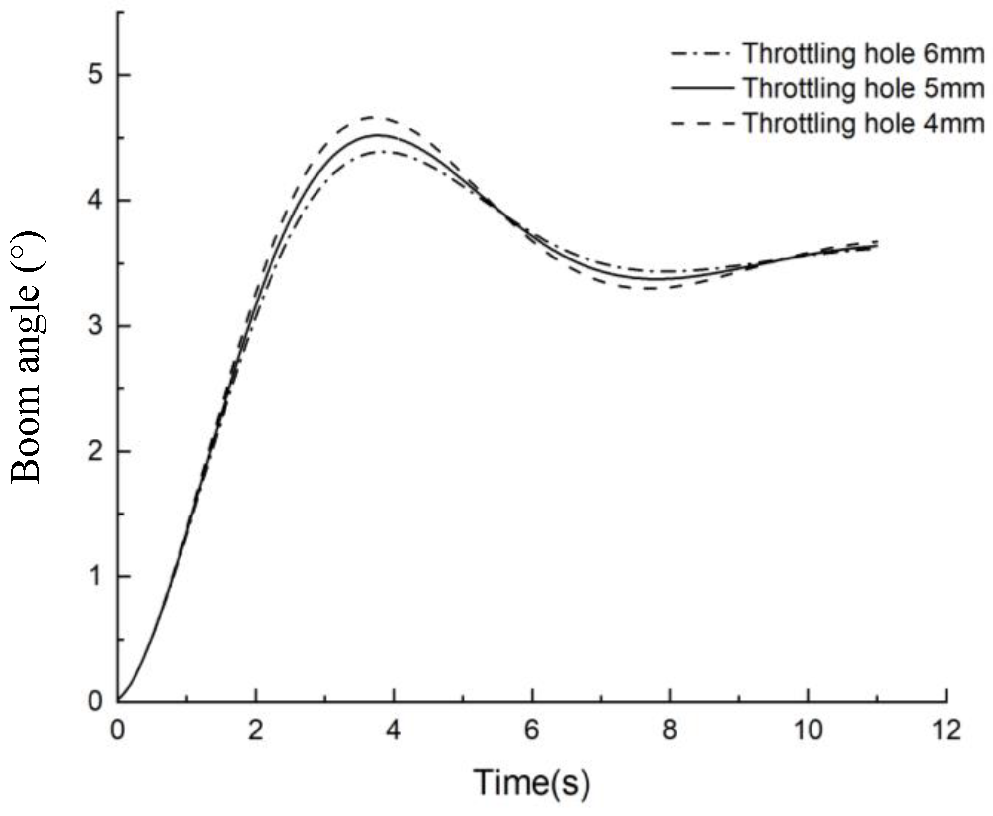
4.1.2. Step Response Analysis

During the working process of the sprayer, if one side of the tire travels across the ridge of the bumpy field, the tractor chassis will tilt, which is equivalent to exerting a step excitation on the passive suspension. The simulation model of boom suspension (Figure 9) is established based on the mathematical model of trapezoidal passive suspension developed in the previous section. The input of the simulation model is a step signal. The step input is provided by moving a box with a certain height under the ultrasonic sensor 1 or 13 (Figure 1). The diameter of the valve orifice is an important parameter that influences the response speed and oscillations of the suspension and boom suspension. Three different valve’s orifices of valve 13 (Figure 2) are set manually to understand the response characteristic of boom suspension at various working parameters. The corresponding parameters of boom suspension are shown in Table 2. The step response is presented in Figure 10 for three different diameters of throttling orifice holes.
Figure 10 implies that the diameter of the orifice has a great influence on the peak value of the step response and the number of oscillations. As the orifice diameter drops, the system damping climbs. Thus, the passive suspension of the boom can reach a stable state more quickly, and the number of oscillations and the maximum overshoot will be reduced. However, if the throttle orifice is set too small, the time to reach the peak value increases, resulting in an increase in the response time of the suspension and a slow response speed. In the above analysis, the orifice diameter of 5 mm is determined for the design of the hydraulic system.

4.1.3. Frequency Domain Response Analysis of Passive Suspension

The second-order model of passive boom suspension can be obtained from the dynamic model of passive suspension when the inclination angle β is small.
C β ¨ = A a ¨ + μ B ( α ˙ β ˙ ) + B α D β
Considering weakly damped structure and ignoring the mechanical friction damping of boom suspension, Equation (14) can be simplified as follows:
C β ¨ = A a ¨ + B α D β
where μ B is boom suspension rotational damping coefficient, N m s/rad;
A = M [ L 0 + L BC 2 tan θ ¯ L AB cos θ ¯ ] [ L G + L BC 2 tan θ ¯ ] B = Mg [ ( L BC / 2 ) [ ( L BC / 2 ) L AB sin 3 θ ¯ ] L AB cos θ ¯ sin 2 θ ¯ L BC 2 tan θ ¯ ] C = I B + M [ L G + L BC 2 tan θ ¯ ] 2 D =   Mg [ ( L BC / 2 ) [ ( L BC / 2 ) L AB sin 3 θ ¯ ] L AB cos θ ¯ sin 2 θ ¯ + L G ]
By applying the Laplace transformation to Equation (15), the transfer function of the boom inclination β and the boom suspension inclination α can be acquired.
β α = H ( s ) = A s 2 + B C s 2 + D
From Equation (16), it can be found that passive suspension belongs to the second-order system, and the characteristic equation of the system is expressed as
C s 2 + D = 0
The natural frequency of the system, ω n ( rad s 1 ) is described as
ω n = ( D C ) 0.5
The main function of passive suspension is to attenuate the excitation from the tractor chassis and road roughness. Equation (16) implies the response characteristics of the passive suspension can be adjusted by the length of twin link rods. The natural frequencies of boom suspension are 0.74   rad s 1 , 1.086   rad s 1 and 1.57   rad s 1   when the lengths of twin link rods are set as 0.38 m, 0.48 m, and 0.58 m, respectively. The corresponding frequency response plot (Figure 11) means the natural frequency increases as twin-link rod length increases, and the amplitude ratio increases slowly and then decreases rapidly to almost the same value. For different initial lengths of link rod, the amplitude ratio of the passive suspension of the spray rod differs greatly at low frequencies. When the frequency exceeds 1.086 rad s 1 , the amplitude ratio decays quickly, which shows the characteristics of high-frequency isolation of the passive suspension.
From the phase-frequency response plot of the passive suspension at the natural frequency, it can be seen that the phase becomes more laggy with the increase in the length of the connecting rod. The length of 0.48 m is determined for twin link rods in mechanical structure design.

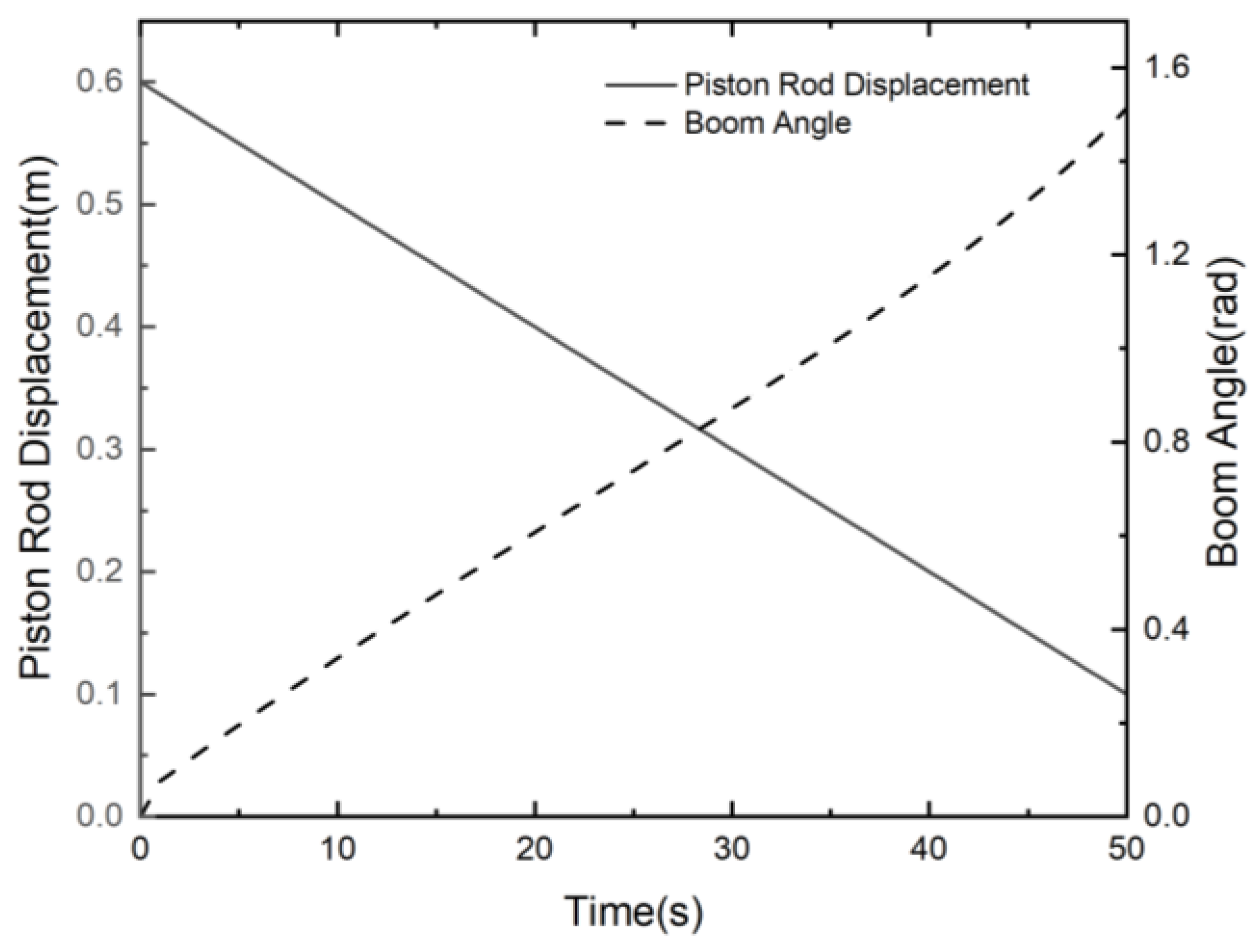
4.1.4. Ground-Following Dynamics Simulation

The simulation for the mathematical model of the ground following the development in the previous section is performed in Matlab/Simulink (Figure 12). The rungkutta numerical integration algorithm is used to solve the differential equations. The correspond− ing simulation results can be seen in Figure 13. Finally, the relationship between cylinder displacement x p and the change in nozzle end height H can be obtained through angle transformation (Figure 14).

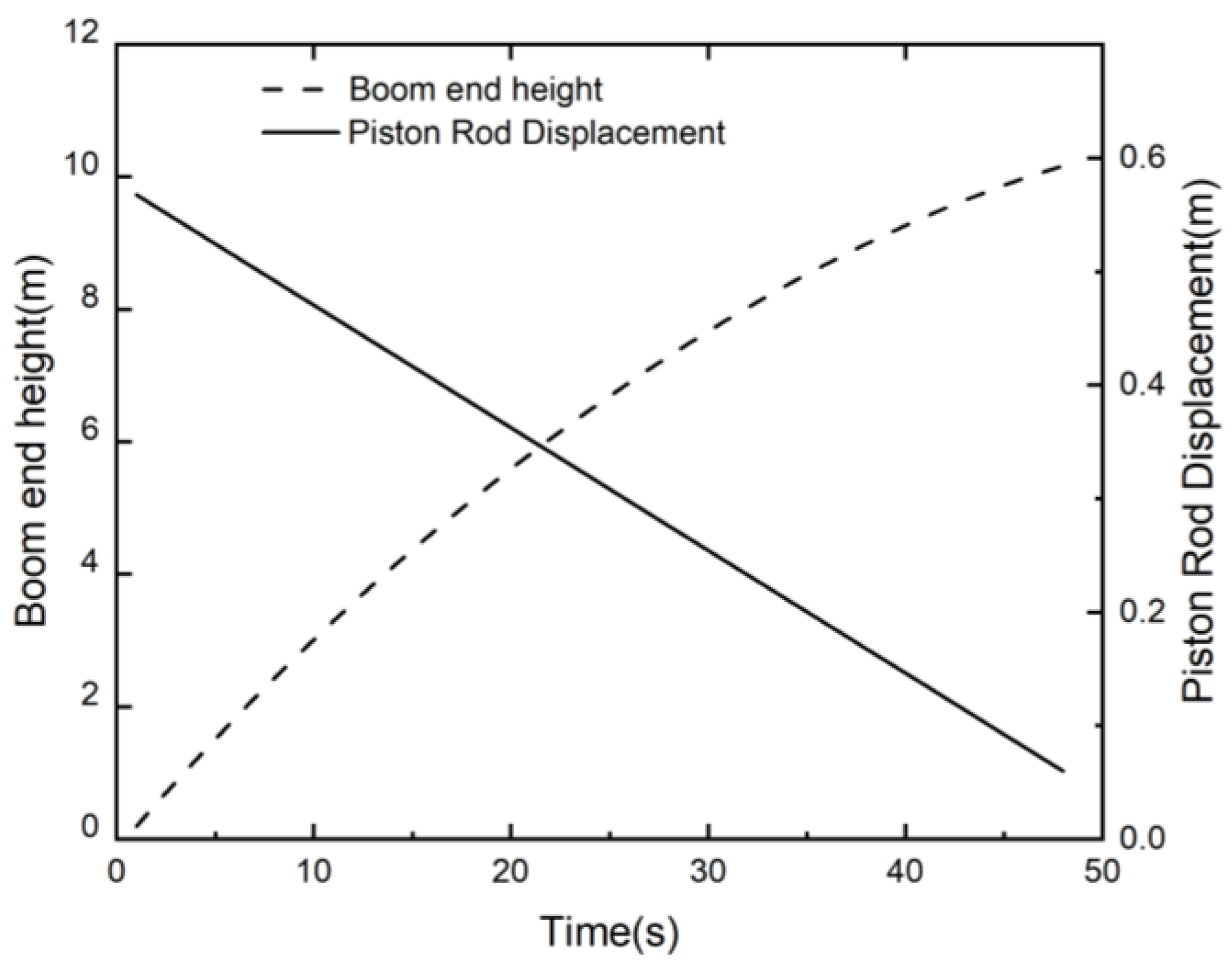
4.1.5. Evaluation of Response Times of the Developed Hydraulic System

The response time of the hydraulic system, which mainly depends on the performance of proportional valves and pipeline lengths between the proportional valves and cylinders, is an important index for evaluating the working efficiency. Considering different pipeline lengths, the reaction times of the ground following the hydraulic system and the active balance hydraulic system are evaluated, respectively. The experiments are designed with 5 replications. First, by inputting various control currents, the opening of the proportional valve is altered, ranging from 10% to 70% (step size 10%) under working pressure of 7 Mpa. Then, the time from the input signal change of the proportional valve to the output signal change of the hydraulic cylinder is recorded by the controller, and the average values of 5 replications are used as the response time. Experimental results indicate that the response time of the ground-following hydraulic system ranges from 0.46 s to 0.62 s, while that of the active balance hydraulic system ranges from 0.39 s to 0.52 s. This implies that the designed hydraulic system has fast response characteristics.
The approximately linear relationship between piston rod displacement of the hydraulic cylinder and the boom end height is found as shown in Figure 14. Within the cylinder stroke range of 0 to 60 cm, the boom end height varied from 0 to 10.6 m. During this process, the maximum force of the imitating cylinder is 4.12 × 10⁴ N (Figure 15). The inversely proportional relationship can be seen between the maximum force of the imitating cylinder and the inclination angle β.

4.2. Experiments and Results

4.2.1. Testing of the Active Balance Control System

The boom suspension was fixed to a six-degree-of-freedom hydraulic motion platform, and the proposed boom control system was set to active balance mode. The experiments were carried out in the laboratory of Jiangsu University. The control parameters of the FPID and PID are k p = 8.0 , k i = 0.5 , k d = 1.5 , determined by trial and error, which denote proportional gain, integrating gain, and differential gain, respectively. The same sinusoidal stimulation x ( t ) = 3 sin ( 0.2 π t )   is output by a six-degree-of-freedom hydraulic motion platform. The PID and FPID control algorithms are operated by the active balance control system. The system outputs with the PID and FPID controllers are shown in Figure 16a, and the corresponding tracking errors are presented in Figure 16c. The performance indexes during the last ten control cycles are presented in Table 3. M a , μ a , and σ denote the maximum, average, and standard deviation of the absolute errors, respectively.
Figure 16b shows that the system output (yout) based on the PID controller lags the input signal (rin) while the system output(yout-upf) based on the FPID control algorithm obtains good tracking performance. The maximum steady-state training error of PID is 0.12°, while the maximum steady-state training error of FPID is 0.03°. As a kind of feedback control, PID adjusts the controlled quantity according to deviation. Under the action of interference, the controlled quantity first deviates from the given value, and then the regulator exerts control action to counteract the effect of interference. Thus, the system output always lags the given value. Moreover, according to the basic principles of feedback control, it is inevitable that there will be steady-state position tracking errors. The feedforward control is an open-loop link that acts according to the compensation principle of the disturbance or the change of the given value. Proper use of the feedforward control system can eliminate the disturbance of the controlled variable in the bud, so that the controlled variable will not be deviated by the disturbance effect or the change of the given value. Compared with the feedback control, it can be controlled in a more timely way and is not affected by the system lag.

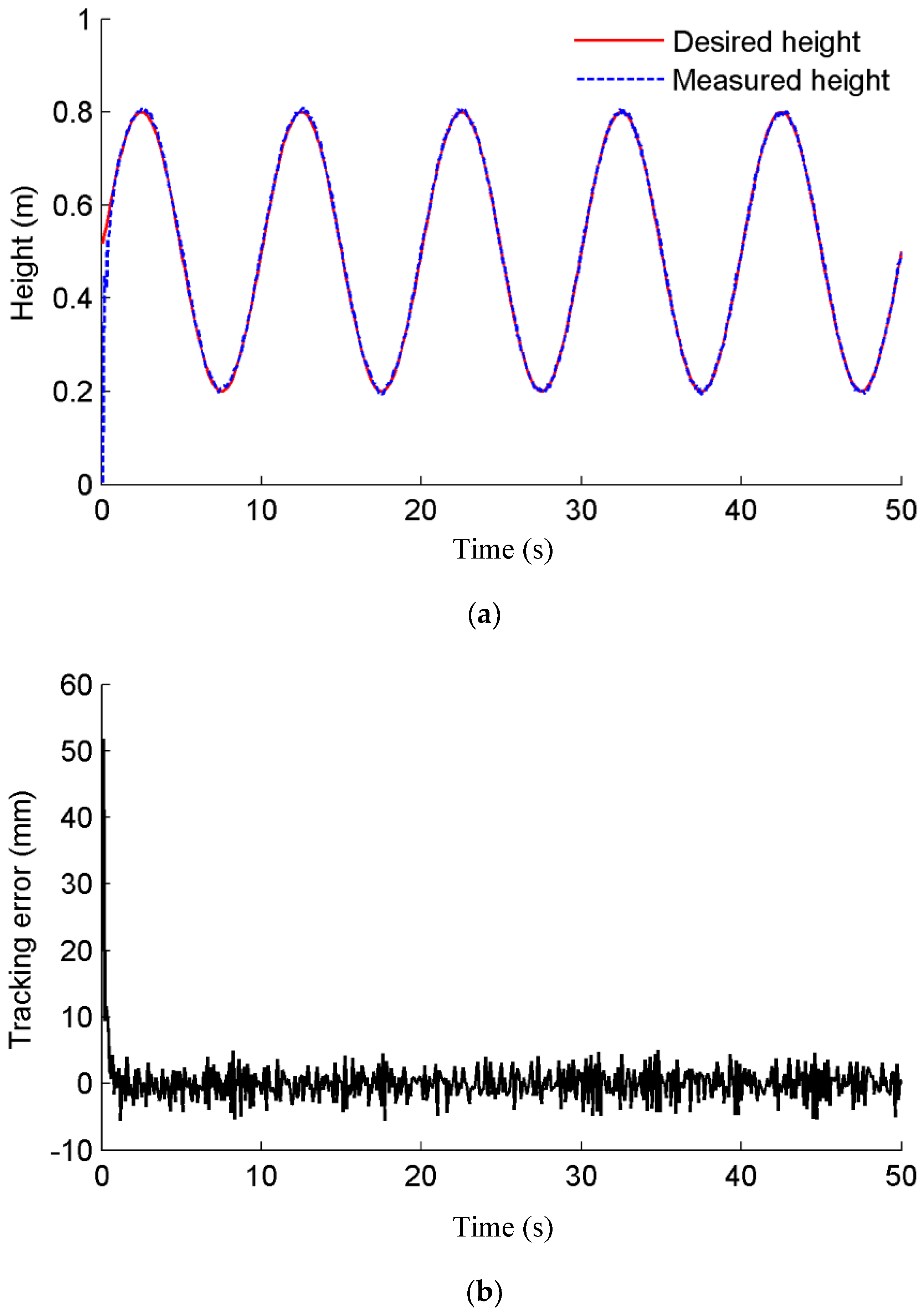
4.2.2. Testing of the Ground Following the Control System

To achieve more consistent droplet distribution and reduce spray drift, it is expected to keep the spray boom parallel to the crop canopy or ground and maintain a certain distance from the spray nozzles to the crop canopy or ground.
To validate the performance of boom automatic following with crop canopy or ground in sloping and undulating terrains, tests for the ground following control system are conducted. The proposed boom control system was set to ground-following mode. A six-degree-of-freedom hydraulic motion platform is adopted to simulate sloping and undulating terrains, and the performance of the FPID controller is evaluated. The control parameters of the FPID controller are k p = 8.0 , k i = 0.5 , k d = 0.5 . The sine signal h ( t ) = [ 0.3 sin ( 0.2 π t ) + 0.5 ]   m   is the input of the ground following the control system. During the adjustment processing of the control systems, the heights from left and right boom arms to ground are recorded by the ultrasonic sensors 1 and 13 (as shown in Figure 1c) assembled on the left and right arms, respectively. The imitating performance of the control system can be seen in Figure 17a. The tracking error can be found in Figure 17b. The maximum absolute error and the standard deviation (SD) are 0.063 m and 8.7 mm, respectively. As can be seen from Figure 17, the measured boom end height is close to the desired height, which implies that the ground following control system has superior following performance and can keep the spray boom parallel to the crop canopy or ground under complex and varied terrain conditions.
In the ground-following control system, the rolling motion of one arm will cause the gravity center change of the entire spray boom and then affect the other arm. It is neces− sary to consider the coupling action between the two boom arms. To solve this problem, we adopted two shutoff valves in the design of the hydraulic system. Each solenoid valve can be controlled by the controller individually. For an active balance control system, the two shutoff valves are opened, and hydraulic oil can pass through the valves. For the ground-following control system, when the boom arms are adjusted, the two shutoff valves are closed, and hydraulic oil is locked in the hydraulic pipes. By the above analysis, good performance of the control system can be seen, and the designed system is effective for less challenging terrain.

4.2.3. Testing of the Ground Following the Control System for Challenging Terrain

Due to the inconsistent soil firmness and bump pit in the field, the single-side tires of the tractor trap into the ground during the spraying of the sprayers, which tilt the boom chassis and cause the boom end to touch the ground. In this unexpected circumstance, the boom wing must be raised as rapidly as possible to avoid damaging the boom. To evaluate the performance of the control system in challenging terrain, a step-response test is carried out. The control parameters of the FPID controller are k p = 8.0 , k i = 0.5 ,   k d = 0.5 . Firstly, the sprayer boom is adjusted to a horizontal position and is 0.8 m above the ground. Then the control system started. A step signal is generated by rapidly moving the carton (0.5 m high) to the bottom of the ultrasonic sensor assembled on the right arm. During the adjustment processing of the control systems, the heights from left and right boom arms to ground are recorded by the ultrasonic sensors 1 and 13 (as shown in Figure 1c) assembled on the left and right arms, respectively. The height difference between the left boom arm and the right boom arm is calculated. The fluctuation of the height difference between the left boom arm and the right boom arm is shown in Figure 18. Two peaks can be observed from Figure 18. At the beginning, the heights between left and right boom arms and ground are both 0.8 m, and the height difference between left and right boom arms is close to 0. At about 5 s, a step signal is generated by rapidly moving the carton (0.5 m in height) to the bottom of the ultrasonic sensor assembled on the right arm. At this moment, the ultrasonic sensor assembled on the right boom arm senses the distance between boom and carton, and this distance is 0.3 m, which is less than the pre-setting height of 0.8 m. Meanwhile, the height between the left boom arm and the ground is 0.8 m. Thus, the height difference between the left and right boom arms is equal to 0.5 m. To regain the pre-setting height between the spray boom and the carton, the right boom arm gradually lifts under the action of the control system. During this process, the height between the left boom arm and the ground still maintains 0.8 m, which results in the height difference between the left and right boom arms gradually decreasing. The height difference between the left and right boom arms is close to 0 again when the distance between the boom and carton reaches 0.8 m.
When rapidly moving the carton away from the bottom of the ultrasonic sensor assembled on the right arm, the ultrasonic sensor assembled on the right boom arm end senses the distance between boom and ground, and this distance is 1.3 m. The corresponding height difference between the left and right boom arms is −0.5 m. The right boom arm gradually falls under the action of the control system, which results in the height difference between the left and right boom arms gradually decreasing. The height difference between the left and right boom arms is close to 0 again when the distance between boom and ground reaches 0.8 m. Compared with the lifting process, the dropping process of the boom is faster. Considering the main aim of this test is to evaluate the response performance of the proposed control system under challenging conditions, the data on the falling process of the spray boom is not presented in this manuscript.
By the above analysis, the peak means the height difference between the left and right boom arms for the moment of moving the carton to the bottom of the ultrasonic sensor assembled on the right arm. To adequately validate the effectiveness of the control system, several repeated experiments are carried out. Figure 18 presents the experimental data for two replications. For the peak at about 23 s (second replication), which is the same as that at about 5 s.
From Figure 18, it can be seen that the difference between the left and right boom arms drops to less than 10% of the initial distance within 1.87 s by the excitation of the step signal at about 5 s and 23 s. This indicates that the proposed control system can achieve precise control in challenging terrain, which ensures the boom end hardly touches the ground or crop canopy under challenging circumstances such as the deflection of the vehicle tires and sinkage of wheels into the ground.

4.2.4. Field Experiment

According to the description of the field experiment in Section 2.5, the field experiments are conducted aiming to evaluate the performance of the boom-controlled system in the hybrid mode of active balance and ground following. The rolling angle variation in the boom and chassis is shown in Figure 19. The statistical analysis of boom inclination angle and chassis inclination angle is given in Table 4.
As can be seen from Figure 19, the chassis waggles violently from the excitation from the soil deformation and bumpy road when the sprayer travels across the slippery and undulating soil. The maximum rolling angle of the chassis is 3.896 ° . Under the regulating action of the proposed control system, the inclination angle of the boom maintains a relatively small range, and the maximum angle is 0.453 ° . It is proven that the designed control system can maintain the boom parallel to the crop canopy or ground while isolating the high-frequency vibration from the chassis. The reason is that the forward feedback control can directly exert the correction effect according to the disturbance quantity when the disturbance occurs. Thus, the VPID effectively eliminates the external disturbance from chassis vibration before the controlled variable has changed. In addition, the precise system model has the premise of eliminating the deviation caused by disturbance, which implies that the developed mathematical models are appropriate and accurate.
A boom control system was developed for traditional pendulum active suspension [15], and field tests were conducted by assembling the developed control system on a 12 m wide boom. Results showed that the maximum roll angle of the boom and the maximum roll angle of the chassis were 0.841° and 4.041°, respectively. By comparison, it can be found that the designed control system in this study, whose obtained performance is slightly higher than that of Ref. [15]. The reason is probably that accurate mathematical models are obtained, which meet the requirements of accurate mathematical models needed for feedforward control.

5. Conclusions

A high-efficiency boom posture adjustment and control system was designed based on the FPID algorithm, which was superior to traditional trapezoid active suspension. The proposed active balance control system not only realized the automatic balance of boom in flat terrains and boom automatic following with crop canopy or ground in sloping and undulating terrains but also achieved the quick raise of boom wing in emergency circumstances such as unilateral tire of sprayer sinkage into the ground quickly and avoid damage because of touching between boom tip and target area (soil and crop canopy). Compared with available active boom control systems, the control system in this study has advantages such as rapid response characteristics, high operating efficiency, and safety.
To clarify the relationship among the structural parameters and damping of the passive suspension and the vibration characteristics of the boom and optimize the low-frequency following performance, the dynamic model of passive boom suspension was developed. The step response characteristic curve of boom suspension for three different orifice diameters and the frequency response characteristics of passive suspension with three different AB lengths were analyzed by simulations. Moreover, to improve the tracking performance of the control system, the FPID control algorithm was designed according to the dynamic model of the active boom system.
The designed control system was assembled on a 24 m boom with trapezoid suspension. The response characteristic of the active boom control system was tested by the step signal and the sinusoidal signal from a six-degree-of-freedom hydraulic motion platform. Firstly, the tracking performance of the active balance control system for the PID and FPID control algorithms was compared for a given 0.2 Hz sine signal. Then, for the ground-following control system, the response characteristics in challenging terrain and tracking performance in less challenging terrain were tested. Field experiment results indicated that the maximum rolling angle of the chassis was 3.896 ° , while the maximum inclination angle of the boom was 0453 ° . The results show that the designed control system can effectively adjust the boom motion in real time and meet the requirements of field operation. Meanwhile, the simulation results were validated by the field tests. In this study, the energy consumption of the proposed control system is not considered, and it is necessary to evaluate it in subsequent research.
The novelty of this study is that it provides an automatic control device with low-cost and high-response performance of spaying height for trapezoidal active suspension, aiming to maintain the desired spraying height from crop canopy or ground in challenging terrain. The main contributions are improving the response performance of boom control devices in challenging terrain and providing a solution to developing a low-cost boom altitude controller that matches the available sprayer. The proposed design methodology, including the hydraulic system and hardware circuit of the boom control system, the performance test of the boom suspension, and the determination of key parameters of the boom suspension and hydraulic system, provides the theoretical basis and practical experience for future low-cost and intelligent boom active control systems. It is of great significance to optimize and upgrade the high-performance active boom suspension in the future.

Author Contributions

Conceptualization, J.L. and Z.N.; methodology, D.G.; software, Z.N.; validation, J.L.; formal analysis, Y.C.; investigation, J.L.; resources, J.L.; data curation, Y.C.; writing—original draft preparation, D.G.; writing—review and editing, M.L.; visualization, M.L.; supervision, J.L.; project administration, J.L. All authors have read and agreed to the published version of the manuscript.

Funding

This research was funded by the Key Research and Development Program of Zhenjiang city (NY2022008), and the Key Research and Development Program of Jiangsu Province (BE2018324).

Institutional Review Board Statement

Not applicable.

Informed Consent Statement

Not applicable.

Data Availability Statement

Not applicable.

Conflicts of Interest

The authors declare no conflict of interest.

Appendix A

Appendix A.1. Mathematic Model of Valve-Controlled Hydraulic Cylinder

The flow equation of an electro-hydraulic proportional valve can be described as
q L = K q x v K c p L
where q L is load flow of electro-hydraulic proportional valve, ( m 3 s 1 ) ; x v spool displacement of proportional valve; m; K c flow-pressure coefficient of proportional valve, m 5 N 1 s 1 ; K q flow gain coefficient of proportional valve, ( m 2 s 1 ); p L loading pressure, ( Pa ) .
The flow continuity equation of a hydraulic cylinder can be expressed as
q L = A p d x p d t + C t m p L + V t 4 β e d p L d t
where A p is hydraulic cylinder cross-sectional area, m 2 ; x p denotes piston rod displacement of hydraulic cylinder, m ;   C t m total leakage coefficient of hydraulic cylinder ,   m 5 N 1 s 1 , C t m = C i m + 1 2 C e m ; ( C i m and C e m are internal and external leakage coefficients, respectively); V t total volume of hydraulic cylinder, proportional valve chamber, and connecting pipes, m 3 ;   β e effective volumetric elastic modulus of hydraulic oil, Pa .
Ignoring the nonlinear static friction, Coulomb friction force, and oil mass, the torque balance equation of the hydraulic cylinder and load based on Newton’s second law can be obtained.
A p p L = m t d 2 x p d t 2 + B p d x p d t + G x p + F L
where m t is the total mass of piston and load, kg ;   B p viscous damping coefficient,   N s m 1 ;   G load spring stiffness, N m 1 ; F L load force, N .
By taking the Laplace transform of Equations (A1)–(A3), the piston displacement of the hydraulic cylinder can be obtained:
x p ( s ) = K q A p x v ( s ) K c e A p 2 ( 1 + V t 4 β e K c e s ) F L ( s ) m t V t 4 β e A p 2 s 3 + ( B p V t 4 β e A p 2 + m t K c e A p 2 ) s 2 + ( 1 + G V t 4 β e A p 2 + B p K c e A p 2 ) s + G K c e A p 2
where K c e   ( K c e = K c + C t m ) , is the total flow-pressure coefficient, m 5 N 1 s 1 .
Considering the load characteristic of boom sprayers is inertial load, the effect of elastic load is negligible ( G = 0 ). In addition, B p K c e A p 2   << 1, Equation (A4) can be simplified as
x p ( s ) = K q A p x v ( s ) K c e A p 2 ( 1 + V t 4 β e K c e ) F L ( s ) s ( s 2 ω h 2 + 2 ζ h ω h s + 1 )
where ω h is undamped hydraulic natural frequency, ω h = 4 β e A p 2 V t m t ,   rad s 1 ;   ζ h is hydraulic damping ratio,   ζ h = K c e A p β e m t V t + B p 4 A p V t β e m t is dimensionless parameter.
Near the steady operating point of the system, Q L ( s ) = K q X v ( s ) . The following transfer functions can be obtained based on Equation (A5).
x p ( s ) Q L ( s ) = 1 A p s ( s 2 ω h 2 + 2 ζ h ω h s + 1 )
x p ( s ) F L ( s ) = K c e A p 2 ( 1 + V t 4 β e K c e s ) s ( s 2 ω h 2 + 2 ζ h ω h s + 1 )
The transfer function of a proportional valve can be described as
G v ( s ) = Q ( S ) I ( S ) = K q s 2 ω v 2 + 2 ζ v s ω v + 1
where ω v   and ζ v   are proportional valve natural frequency and damping ratio, respectively.
The transfer functions of hydraulic cylinder speed to flow and external load can be obtained, respectively.
x p ( s ) Q ( s ) = 1 A p s 2 ω h 2 + 2 ζ h ω h s + 1
x p ( s ) F L ( s ) = K c e A p 2 ( 1 + V t 4 β e K c e s ) s 2 ω h 2 + 2 ζ h ω h s + 1
where K c e A p 2 ( 1 + V t 4 β e K c e s ) = K T .
Considering the angle sensor as a proportional element, the transfer function of the displacement sensor can be written as
K f = U ( s ) x p ( s )
where K f is angle sensor gain, V s m 1 .
The E-ME-L-01 type proportional amplifier is used with the electro-hydraulic proportional direction valve. The voltage-rated input value is U 0 = 10 ( V ) and the corresponding rated output current is I 0 = 3 ( A ) , therefore, proportional amplifier gain K a can be expressed as
K a = I 0 U 0 = 3 10 = 0.3 ( A V 1 )

Appendix A.2. Dynamic Model of an Active Balance System

According to the projection relationship, the coordinate (x, y) of the center of mass of boom G relative to O can be described as:
{ x = L 0 s i n α + 1 2 L AD c o s α + L CD s i n θ 2 1 2 L BC c o s β L G s i n β x = L 0 s i n α 1 2 L A D c o s α L AB s i n θ 1 + 1 2 L BC c o s β L G s i n β   ( lean   to   left )
{ y = L 0 c o s α + 1 2 L AD s i n α L AB c o s θ 1 1 2 L BC s i n β L G c o s β y = L 0 c o s α 1 2 L AD s i n α L CD c o s θ 2 + 1 2 L BC s i n β L G c o s β   ( lean   to   right )
where   L A D , L AB , L BC and L CD are the AD, AB, BC and CD lengths, respectively, m; L o vertical distance between the center of the link AD and the ground, m; α and β are inclination angles of suspension and boom relative to the horizontal plane, respectively, rad; L G the vertical distance from the center mass of boom to BC, m.
In trapezoidal suspension ABCD, the initial Angle between the vertical direction and link rods AB and DC both are θ ¯ , thus θ ¯ can be expressed as:
θ ¯ = a r c s i n ( L BC L AD L AB + L CD )
In the process of boom movement, given that the change range of α ,   β ,   θ 1 and   θ 2 are relatively small, the coordinate (x, y) can be expressed as:
{ x = ( L 0 + c o s θ ¯ 2 s i n θ ¯ L AD ) α ( L G + c o s θ ¯ 2 s i n θ ¯ L BC ) β y = L 0 L G 1 2 ( L 0 α 2 L G β 2 ) + c o s θ ¯ 4 s i n θ ¯ ( L AD α 2 L BC β 2 )
{ Δ θ 2 1 2 L C D [ L A D α 2 2 c o s θ ¯ L B C β 2 2 c o s θ ¯ L B C β s i n θ ¯ + L A D α s i n θ ¯ ] Δ θ 1 1 2 L A B [ L A D α 2 2 c o s θ ¯ L B C β 2 2 c o s θ ¯ L A D α s i n θ ¯ + L B C β s i n θ ¯ ]
Obviously, the derivative of x and y can be achieved from Equations (A16) and (A17):
{ x = ( L 0 + c o s θ ¯ 2 s i n θ ¯ L AD ) α ( L G + c o s θ ¯ 2 s i n θ ¯ L BC ) β x = ( L 0 + c o s θ ¯ 2 s i n θ ¯ L AD ) α ( L G + c o s θ ¯ 2 s i n θ ¯ L BC ) β
{ y = ( c o s θ ¯ 2 s i n θ ¯ L AD L 0 ) α α ( c o s θ ¯ 2 s i n θ ¯ L BC L G ) β β y = ( c o s θ ¯ 2 s i n θ ¯ L AD L 0 ) ( α α + α α ) ( c o s θ ¯ 2 s i n θ ¯ L BC L G ) ( β β + β β )
where Δ θ 1 and Δ θ 2 are the variation quantity of θ 1 and θ 2 , respectively, rad.
According to the dynamic equilibrium equation,
M x = T 1 sin θ 3 T 2 sin θ 4 + F 1 sin θ 1 + F 2 sin θ 2
M y = T 1 cos θ 3 T 2 cos θ 4 + F 1 cos θ 1 + F 2 cos θ 2 M g
I B β = T 1 L M N 2 cos θ 7 + T 2 L M N 2 cos θ 8 + F 1 ϕ 1 F 2 ϕ 2
ϕ 1 = L G cos θ 5 + L B C 2 sin θ 5
ϕ 2 = L G cos θ 6 + L B C 2 sin θ 6
F 1 and F 2 are the forces of link rods AB and CD, respectively, N; T 1 and T 2 are equivalent damping forces of the left-side and right-side balance cylinders, N; M boom mass, kg; I B Moment of inertia of boom about mass center, kg · m 2 ; θ 5 and θ 6 —intersection angles between connecting rod AB, CD and boom, respectively, rad.
It can be found that the transfer function of the hydraulic control valve and piston can be obtained by Equation (A5)
x p ( s ) x v ( s ) = k 1 s ( k 2 s 2 + k 3 s + 1 )
where k 1 = K q A p , k 2 = 1 ω h 2 , k 3 = 2 ζ h / ω h .
Assume that the hydraulic oil is incompressible and sufficient hydraulic pressure enables the piston to move independent of its load, thus k 2 = 0 and k 3 = 0 [9].
x v ( s ) γ β = k 4 T s + 1
where   k 4 is the gain of valve and transfer function, m/rad.
The transfer function of inclination transducer mounted on the boom to the hydraulic valve displacement can be written as [7]
x p γ β = K s ( T s + 1 )
Considering that the increment in length of ME or MF is equal to the piston displacement increment Δ L b , and thus the overall transfer function for transducer, the valve and piston combination can be rewritten as
G ( s ) = Δ L b γ β = K s ( T s + 1 ) = B s 2 + A s
where K = k 1 k 4 , B = K / T ; A = 1 / T ; γ inclination of ground to horizontal (rad);   β inclination of boom to horizontal (rad); T time constant of valve and transducer transfer function; s Laplace operator; k 1 , k 2 ,   k 3 coefficients of valve and piston transfer function, Equation (A24); k 1 gain of valve and transducer transfer function.
The behavior of the active suspension can be predicted by the simultaneous solutions of Equations (A13)–(A24) and (A28).

References

  1. Zhuang, T.F.; Yang, X.J.; Dong, X.; Zhang, T.; Yan, H.R.; Sun, X. Research status and development trend of large self-propelled sprayer booms. Trans. Chin. Soc. Agric. Mach. 2018, 49, 189–198. (In Chinese) [Google Scholar]
  2. Visacki, V.; Sedlar, A.; Gil, E.; Bugarin, R.; Turan, J.; Janic, T.; Burg, P. Effects of sprayer boom height and operating pressure on the spray uniformity and distribution model development. Appl. Eng. Agric. 2016, 32, 341–346. [Google Scholar]
  3. Balsari, P.; Gil, E.; Marucco, P.; van de Zande, J.C.; Nuyttens, D.; Herbst, A.; Gallart, M. Field-crop-sprayer potential drift measured using test bench: Effects of boom height and nozzle type. Biosyst. Eng. 2017, 154, 3–13. [Google Scholar] [CrossRef]
  4. Cui, L.F.; Xue, X.Y.; Le, F.X.; Mao, H.P.; Ding, S.M. Design and experiment of electro-hydraulic active suspension for controlling the rolling motion of spray boom. Int. J. Agric. Biol. Eng. 2019, 12, 72–81. [Google Scholar] [CrossRef]
  5. Yan, J.C.; Xue, X.Y.; Cui, L.F.; Ding, S.M.; Gu, W.; Le, F.X. Analysis of dynamic behavior of spray boom under step excitation. Appl. Sci. 2021, 11, 14–24. [Google Scholar] [CrossRef]
  6. Sun, W.F.; He, Y.; Fu, T.P.; Wang, J.; Lu, J.Q.; Chang, J.K. Design and test of horizontal folding spray boom of sprayer. Trans. Chin. Soc. Agric. Mach. 2021, 53, 116–127. [Google Scholar]
  7. Manea, D.; Gidea, M.; Marin, E.; Mateescu, M. Simulation of mechanical parameters of sprayer boom. In Proceedings of the 17th International Scientific Conference on Engineering for Rural Development, Jelgava, Latvia, 23–25 May 2018; pp. 45–51. [Google Scholar]
  8. Lebeau, F.; El Bahir, L.; Destain, M.F.; Kinnaert, M.; Hanus, R. Improvement of spray deposit homogeneity using a PWM spray controller to compensate horizontal boom speed variations. Comput. Electron. Agric. 2004, 43, 149–161. [Google Scholar] [CrossRef]
  9. Satow, T.; Miyamoto, K.; Matsuda, K. Control of spraying height with ultrasonic sensor for boom sprayer (part 2)-Development of automatic control device for spraying height. J. Jpn. Soc. Agric. Mach. 1994, 56, 59–67. [Google Scholar]
  10. Anthonis, J.; Ramon, H.; Baerdemaeker, J.D. Implementation of an active horizontal suspension on a spray boom. Trans. ASAE 2000, 43, 213–220. [Google Scholar] [CrossRef]
  11. Deprez, K.; Anthonis, J.; Roman, H.; Van Brussel, H. Development of a slow active suspension for stabilizing the roll of spray booms, part 1: Hybrid Modelling. Biosyst. Eng. 2002, 81, 185–191. [Google Scholar] [CrossRef]
  12. Nuyttens, D.; Zwertvaegher, I.K.; Dekeyser, D. Spray drift assessment of different application techniques using a drift test bench an comparison with other assessment methods. Biosyst. Eng. 2016, 154, 14–24. [Google Scholar] [CrossRef]
  13. Cui, L.F.; Xue, X.Y.; Ding, S.M.; Le, F.X. Development of a DSP-based electronic control system for the active spray boom suspension. Comput. Electron. Agric. 2019, 166, 105024. [Google Scholar] [CrossRef]
  14. Tan, H.R.; Dou, H.J.; Zhai, C.Y.; Li, Y.K.; Yang, S.; Chen, L.P. Design and test of boom height control system for boom sprayer. J. Agric. Mech. Res. 2021, 6, 156–160. [Google Scholar]
  15. Dou, H.J.; Zhai, C.Y.; Chen, L.P.; Wang, S.L.; Wang, X. Field variation characteristics of sprayer boom height using a newly designed boom height detection system. IEEE Access 2021, 9, 17148–17160. [Google Scholar] [CrossRef]
  16. Tahmasebi, M.; Mailah, M.; Gohari, M.; Abd Rahman, R. Vibration suppression of sprayer boom structure using active torque control and iterative learning. Part I: Modelling and control via simulation. J. Vib. Control 2018, 24, 4689–4699. [Google Scholar] [CrossRef]
  17. Andrea, W.; Miklos, K. State feedback controller design of an active suspension system for vehicles using pole placement techenique. Acta Tech. Jaurinensis 2019, 12, 178–190. [Google Scholar]
  18. Xue, T.; Li, W.; Du, Y.F.; Mao, E.R.; Wen, H.J. Adaptive fuzzy sliding mode control of spray boom active suspension for large high clearance sprayer. Trans. CSAE 2018, 34, 47–56. (In Chinese) [Google Scholar]
  19. Anthonis, J.; Ramon, H. Design of an active suspension to suppress the horizontal vibrations of a spray boom. J. Sound Vib. 2003, 266, 573–583. [Google Scholar] [CrossRef]
  20. Available online: https://amazone.co.uk/ (accessed on 8 November 2023).
  21. Available online: https://lemken.com/en-en/# (accessed on 6 November 2023).
Figure 1. Boom suspension geometry. (a) boom balance; (b) boom imitation; (c) boom balance and boom imitation: 1, 8, 12—Ultrasonic sensor; 2, 7—balance hydraulic cylinder; 3, 10—inclination angle sensor; 4—link rods of trapezoidal suspension; 5—boom suspension; 6—boom chassis; 9—mechanical limit device; 11—lift hydraulic cylinder; 13—sprayer boom; 14—left imitating hydraulic cylinder; 15—right imitating hydraulic cylinder; 16—center frame of boom.
Agriculture 13 02162 g001aAgriculture 13 02162 g001b
Figure 2. Schematic diagram of the hydraulic system. (A) active balance hydraulic circuit; (B) lifting hydraulic circuit of the entire boom suspension; (C) ground imitation circuit, and (D) oil supply circuit: 1—oil filter; 2—constant displacement pump; 3—overflow valve; 4—oil cooler; 5—constant difference overflow valve; 6—pressure relief opening; 7—damper 8, 9—active balance hydraulic cylinder; 10, 18, 23—one-way throttle valve; 11—shuttle valve; 12—two-position two-way solenoid valve; 13, 20, 21, 22—three-position four-way proportional valve; 14—pressure compensator; 15—sensing one-way valve; 16—lifting hydraulic cylinder; 17, 24—energy accumulator; 19—balance valve; 25, 26—imitation hydraulic cylinder.
Agriculture 13 02162 g002
Figure 3. Schematic diagram of the controller.
Agriculture 13 02162 g003
Figure 4. Test bench of the boom control system. 1—hydraulic power unit; 2—boom and trapezoid suspension; 3—control valves; 4—control computer of hydraulic test bench; 5—six degrees freedom motion planform; 6—boom controller.
Agriculture 13 02162 g004
Figure 5. Tractor and boom suspension. 1—ultrasonic sensor; 2—inclination sensor of boom; 3—inclination sensor of chassis; 4—imitation cylinders; 5—active balance cylinder.
Agriculture 13 02162 g005
Figure 6. Boom suspension geometry.
Agriculture 13 02162 g006
Figure 7. Ground following geometric model.
Agriculture 13 02162 g007
Figure 8. Block diagram of the control system.
Agriculture 13 02162 g008
Figure 9. Simulation model of passive boom suspension.
Agriculture 13 02162 g009
Figure 10. Step response characteristic curve of boom suspension.
Agriculture 13 02162 g010
Figure 11. Frequency response characteristics of passive suspension with different AB lengths.
Agriculture 13 02162 g011
Figure 12. Dynamic simulation model for ground following of the boom suspension.
Agriculture 13 02162 g012
Figure 13. Relationship between cylinder displacement x p and β.
Agriculture 13 02162 g013
Figure 14. Relationship between cylinder piston displacement and nozzle end height.
Agriculture 13 02162 g014
Figure 15. Force variation in an imitating cylinder.
Agriculture 13 02162 g015
Figure 16. Comparison of two controllers for an active boom control system. (a) Tracking perfor− mance for two controllers; rin: input signal; yout: PID; yout-upf: FPID; (b) Local amplification of (a); (c) Tracking error for the two controllers.
Agriculture 13 02162 g016aAgriculture 13 02162 g016b
Figure 17. Tracking performance for the ground following the control system. (a) Desired height and measured height; (b) imitating error.
Agriculture 13 02162 g017
Figure 18. Height difference between left and right boom arms.
Agriculture 13 02162 g018
Figure 19. Rolling angle variation in boom and chassis in a field experiment.
Agriculture 13 02162 g019
Table 1. Definition of variables and factors for three different control modes.
Control Mode I n p u t   V a r i a b l e s O u t p u t   V a r i a b l e s F a c t o r s
Active   balance   θ a L b S t , S v
Ground   following H b L i S t , S v
Active balance and ground following θ a , H b L b , L i S t , S v
Table 2. Parameters of passive boom suspension.
SignParameter SignatureParameter ValueUnit
L G 1 Length of boom gravity to MN0.198m
L G Length of boom gravity to BC0.200m
L ¯ E M Initial length of left active balance hydraulic cylinder0.520m
L ¯ F N Initial length of right active balance hydraulic cylinder0.520m
L M N Length of MN1.420m
L E F Length of EF1.344m
I B Moment of inertia of boom about mass center1.488 × 104kg·m2
M Mass of boom535kg
θ ¯ Initial angle between AB/DC and vertical direction1.05–0.52rad
L 0 Length shown in Figure 42.00m
L AB Length of AB0.37m
L CD Length of CD0.37m
L AD Length of AD0.48m
L BC Length of BC0.80m
Table 3. Performance indicators under the action of two controllers.
Indexes M a / ° μ a ° σ / °
PID 0.120.0430.039
FPID 0.030.0120.009
Table 4. Statistical analysis of boom inclination angle and chassis inclination angle.
Indexes M a / ° μ a ° σ / °
Chasis 3.8960.9840.826
Boom 0.4530.1300.117
Disclaimer/Publisher’s Note: The statements, opinions and data contained in all publications are solely those of the individual author(s) and contributor(s) and not of MDPI and/or the editor(s). MDPI and/or the editor(s) disclaim responsibility for any injury to people or property resulting from any ideas, methods, instructions or products referred to in the content.

