Article

Design of High-Efficiency Soil-Returning Liquid Fertilizer Deep-Application Furrow Openers for Improving Furrowing Performance in Cold Regions of Northeast China

1
College of Engineering, Northeast Agricultural University, Harbin 150030, China
2
Department of Industrial and Manufacturing Systems Engineering, The University of Hong Kong LG-108, Composite Building, Pokfulam Road, Hong Kong SAR 999077, China
3
Key Laboratory of Crop Harvesting Equipment Technology of Zhejiang Province, Jinhua Polytechnic, Jinhua 321007, China
*
Author to whom correspondence should be addressed.
Agriculture 2022, 12(9), 1286; https://doi.org/10.3390/agriculture12091286
Submission received: 21 July 2022 / Revised: 18 August 2022 / Accepted: 18 August 2022 / Published: 23 August 2022
(This article belongs to the Special Issue Advances in Agricultural Engineering Technologies and Application)

Abstract

:
Liquid-fertilizer deep-application techniques are techniques for applying fertilizers to the root system of crops, which can effectively improve the utilization rate of fertilizers and reduce application amounts. Due to the soil viscosity of soils in the cold region of Northeast China, the soil return rate of furrow openers for liquid-fertilizer deep applications is low, which can easily cause excessive volatilizations of liquid fertilizers. Therefore, aiming at the operational requirements of low soil disturbance for liquid-fertilizer furrowing and deep applications, an efficient soil-returning liquid-fertilizer deep-application furrow opener was innovatively designed based on soil characteristics during the inter-cultivation period in the cold region of Northeast China. The discrete element method (DEM) was used to analyze the operating performance of the high-efficiency soil-returning liquid-fertilizer deep-application furrow openers, which is determined by key operating parameters including width and slip cutting angle. The DEM Virtual Simulation Experiment results show that the optimal combination is the width of 37.52 mm and a slip cutting angle of 43.27°, and the test results show that the optimal performance of the high-efficiency soil-returning liquid-fertilizer deep-application furrow opener is that the soil disturbance rate is 51.81%, and the soil-returning depth is 52.1 mm. This paper clarifies the relationship between the width and the slip cutting angle in furrowing resistance and soil disturbance and the mechanism by which the width and slip cutting angle affect soil disturbance. Above all, this study provides a theoretical and practical reference for the design of liquid-fertilizer deep-application furrow openers.

1. Introduction

The soil type in the cold region of Northeast China is a very rare cold black soil with a very slow formation rate, which is a very valuable resource [1,2,3]. Since the beginning of the second “green revolution” in the world, the application of chemical fertilizers has surged in most countries in the world, and the crop quality and per capita output of grain have significantly improved [4,5]. At the same time, the long-term large-scale application of chemical fertilizers has also introduced many problems, such as the decline of black soil fertility, the destruction of soil aggregate structure, and the excessive pollution of farmland environment [6,7,8,9]. Therefore, curbing the excessive use of chemical fertilizers can effectively protect valuable black soil resources in this region [6,10,11].
In recent years, liquid fertilizers have been widely used due to its advantages in convenient production, possessing a flexible ratio, low environmental pollution and high crop-absorption rates, which can effectively curb the excessive application of chemical fertilizers [10,11]. In agricultural production, the methods of furrowing and the deep application of liquid fertilizers effectively improved fertilizer utilization rates [12,13]. However, the commonly used furrow opener for deep applications of liquid fertilizers is prone to causing large soil disturbances, resulting in high volatilization rates of liquid fertilizers and affecting crop growth and the promotion of liquid-fertilizer deep-application techniques [13,14,15]. Obviously, in order to successfully promote the application of liquid-fertilizer deep-applications technique, a liquid-fertilizer deep-application furrow opener that can realize highly efficient soil returns during operation is needed, which will greatly improve the promotion of liquid-fertilizer deep-application techniques in this region.
Many scholars have studied and analyzed the interaction between furrow openers and soil. Godwin and Spoor [16,17] analyzed soil disturbances caused by furrow openers by using the soil bin test, and they concluded that soil disturbances as two approximate geometric contours comprising a wedge and a crescent. These studies treat the soil as a whole and analyze soil disturbances through the damage introduced by furrow openers to whole soil without considering the interaction between soil particles; thus, the construction of the analysis model in the above studies is not sufficient. Solhjou et al. [18] conducted an experimental study on soil disturbance caused by narrow point openers and quantified the furrow contour by using cubic PVC missing agents embedded in the soil. The results showed that the chamfer of the furrow opener significantly reduced soil disturbances. Rodhe and Etana [19] developed V-shaped discs, which reduced the loss rate of liquid fertilizers compared with band spreading, but furrowing resistance was too large, which led to a wide shape and a superficial depth and caused an excessive volatilization of the liquid fertilizer. The above studies show that the innovative design of the furrow opener’s geometry can achieve low soil-disturbance rates and reduce the rate of liquid fertilizer volatilization. Therefore, the structural innovative design of the liquid-fertilizer deep-application furrow opener can significantly improve its operation performance. Shuhong et al. [20] designed a new opener to reduce the working resistance of the furrow opener by conducting a bionic study of the sailfish head curve and concluded that the working resistance, the width of soil disturbance and the depth of soil return increased with the increase in furrow-opening depth at a water content of 12% ± 1%. At the furrow opening depth of 60 mm, the working resistance increased with the increase in water content. However, the effects on soil disturbance width and soil-return depth were not obvious.
Many scholars evaluated the performance of new openers by computer simulation tests. Computer-aided design and simulation tests can reduce the number of test steps, save test costs and reduce the resources required for the design and manufacture of openers [21]. Ever since the discrete element method (DEM) has been proposed, the use of discrete element methods to construct coupled opener–soil interaction models has been proven by many scholars to be effective, and it is an efficient method for studying granular media with dynamics and optimal design [22,23].
In this study, a DEM virtual-simulation model of black soil in the cold region of Northeast China was constructed by sampling and measuring the relevant parameters of the black soil widely distributed in the cold region of Northeast China, and an optimal test has been carried out for the key structural parameters of liquid-fertilizer deep-application furrow openers. Moreover, a high-efficiency soil-returning liquid-fertilizer deep-application furrow opener with excellent operating performances was designed. The accuracy of the DEM virtual simulation test model is verified by the soil bin test. This study can provide research ideas and design methods for the design of liquid-fertilizer deep-application furrow openers. At the same time, it can facilitate the promotion of liquid-fertilizer deep-application techniques in the cold regions of Northeast China, reduce the amount of chemical fertilizer application in local areas, and protect precious black soil resources.

2. Materials and Methods

2.1. DEM Virtual Simulation Test

2.1.1. Measurement of Physical Parameters of Black Soil

As one of the three major corn-producing areas in China, the black soil in the main corn-producing area of Northeast China was selected for sampling and determination, and the soil was sampled at a test plot (126°58′31″ N, 45°32′29″ E) in Acheng District, Harbin, Heilongjiang province, China, on 25 June 2021. The bulk density of black soil was measured using the cutting ring method. Measuring equipment comprised an aluminum cutting ring (100 cm3) and an electronic balance (accuracy 0.01 g, Changzhou Lucky Electronic Equipment Co., Ltd., Changzhou, China), as shown in Figure 1a. The moisture content of the black soil was measured by the oven drying method [24], and measuring equipment included an electric constant-temperature drying box (Model GZ008, Dongguan Bai hui Electronic Co., Ltd., Dongguan, China), as shown in Figure 1b. The soil shear modulus and Poisson’s ratio were measured using a strain-controlled soil direct-shear apparatus (Model ZJ, Changzhou Lingkun Automation technique Co., Ltd., Changzhou, China), as shown in Figure 1c.

2.1.2. Measurement of Black Soil Contact Parameters

In this study, the sliding and rolling friction coefficients of soil and 65 Mn material were measured by using a slope test, as shown in Figure 2a. The collision recovery co-efficient between the soil and 65 Mn material was measured by a collision test. The measuring equipment included a high-speed camera (PCO.DIMAX CS4 model, Kelheim, Bagolia, Germany). After the collision between spherical soil and a 65 Mn steel plate, the ratio of the normal rebound velocity to the normal forward velocity before the collision was used to determine the collision’s recovery coefficient, as shown in Figure 2b.

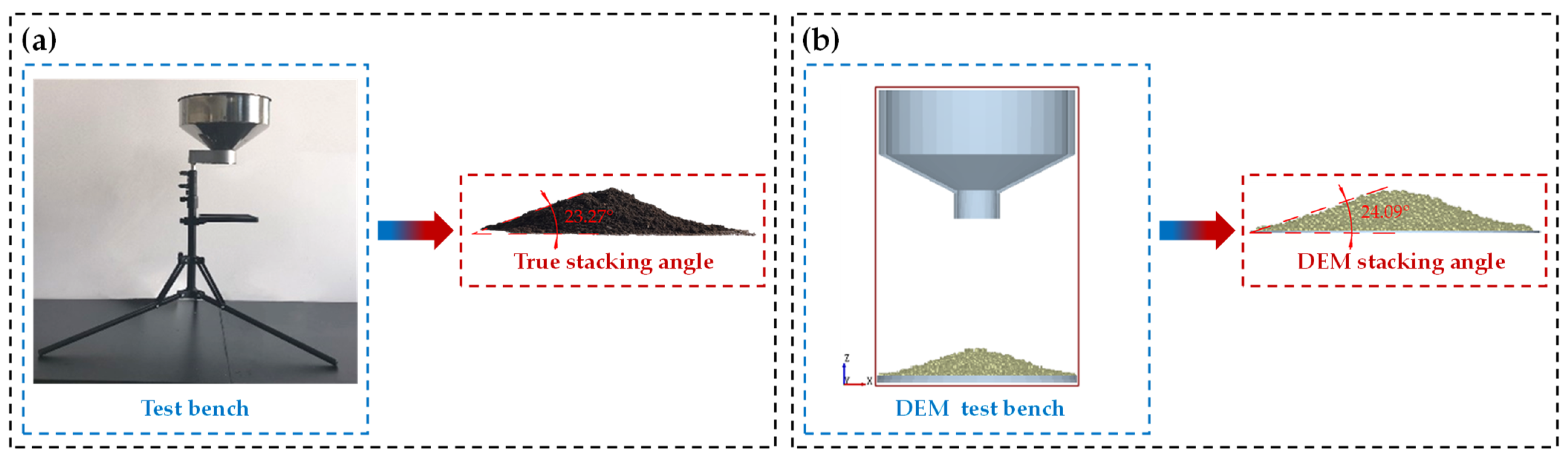
2.1.3. Setting and Calibration of DEM Virtual Simulation Parameters

The soil in the cold region of Northeast China comprises black soil with high moisture content; thus, the contact model should fully consider the effect of inter-particle cohesion force on particle movements [25,26]. The Hertz-Mindlin with the JKR Cohesion contact model in EDEM is a cohesion contact model. Based on the Hertz contact theory and JKR theory, it considers the influence of the inter-particle cohesion force on particle movement, and it is suitable for simulating material bonding and agglomeration between particles due to electrostatic, moisture and other reasons, such as crops and soil. When using Hertz-Mindlin with the JKR Cohesion contact model to simulate black soil, the contact model parameter (that is, the surface energy density) needs to be determined. This parameter cannot be obtained directly and is determined by the stacking angle test.
Select a hopper with an inlet diameter of 300 mm, outlet diameter of 50 mm and height of 270 mm; adjust the position of the hopper to a distance of 250 mm between the bottom of the outlet and the plate; close the outlet; fill the hopper with soil and then open the outlet. After the soil on the plate is stable, shoot it in a perpendicular manner to the horizontal plane and the marked stacking angle.
Using EDEM 2020 to carry out the soil stacking angle simulation test, the contact model parameters were corrected and calibrated with the real soil stacking angle as the target. The stacking angle method is used to measure the surface energy density in order to reduce the error between the simulation results and the actual test results.
After correcting the surface energy density several times, when the surface energy density of the contact model was finally determined to be 5.5 J m−2, the real stacking angle of soil and the simulated stacking angle are basically the same, which are 23.27° and 24.09° respectively. The measurement process and results are shown in Figure 3.

2.1.4. DEM Virtual Simulation Soil Bin Construction

In order to efficiently carry out the DEM virtual simulation test, a single spherical particle is selected as the virtual soil particle model [27]. In order to render the virtual soil as close as possible to actual soil conditions in the field, the EDEM virtual soil parameters were set according to physical and mechanical property parameters, contact model parameters and material contact parameters of the soil measured in the previous stage, and a virtual soil model was constructed. The virtual soil parameters are shown in Table 1.

2.1.5. DEM Virtual Simulation Model Construction

In order to clearly and intuitively observe the operation process of the furrow opener, a soil model was constructed with a thickness of 20 mm, and the soil at a depth of 0–100 mm was used as the operation layer. The soil particles were randomly generated in this depth and settled naturally, with 120,000 particles in each layer. The soil at a depth of 100–140 mm was used as a buffer layer, which was used to isolate the operation layer and the boundary of the soil bin so as to avoid the excessive extrusion of the soil by the boundary of the soil bin during the simulation, which will affect simulation results. The preparation area and the data collection area are set along the operation direction of the furrow opener of the virtual soil bin. The length of the preparation area is 100 mm, which is the buffer area for the furrow opener to enter the soil for stable operations. The length of the data collection area is 1400 mm, which is the stable operation area of the furrow opener for data collection.
To sum up, the overall size of virtual soil is determined to be 1500 mm × 600 mm × 140 mm, as shown in Figure 4a. The Creo 6.0 software was used to construct a model for the high-efficiency deep-application furrow opener. The interaction between the furrow opener and soil can be divided into five processes: cutting, lifting and crushing, pushing, guiding and shaping. In order to realize the above processes, the sliding–cutting edge and curved surface structure are designed with symmetrical layouts. Based on the sliding and cutting principle, the head of the furrow opener is designed as the sliding–cutting edge to achieve the cutting of soil. The surface structure was designed based on the structural characteristics of wedge-surface crushing and the extruding soil, including disturbed soil surfaces, extruded soil surfaces, guide inclined surfaces and shaping surfaces. The disturbed soil surface improves the soil crushing ability of the high-efficiency soil-returning liquid-fertilizer furrow opener. The wedge structure is helpful for breaking the upper soil layer and for promoting soil flow from the surface of the furrow opener to the tail of the furrow opener. The extruded soil surface squeezes and cuts the soil, which is beneficial for forming smooth fertilizer furrows quickly and efficiently. The inclined surface guides the falling soil to fall behind the fertilizer spray needle in order to realize the falling soil and overlaying fertilizer. The shaping surface extrudes the soil sideways in order to shape the fertilizer’s furrow. The fertilizer spray needle is embedded in the tail of the high-efficiency soil-returning liquid-fertilizer furrow opener as a fertilizer-spraying execution component, as shown in Figure 4b. After all models are constructed, the high-efficiency soil-returning liquid-fertilizer furrow opener is imported into the EDEM 2020 software (Altair Engineering, Inc., Troy, MI, USA) for DEM simulation tests, and the post-processing module is used to obtain test results, as shown in Figure 4c.
The operating performance of the furrow opener is related to the slip cutting angle θ2 and width l. In this study, 2 factors and 5 levels were used to conduct the DEM simulation test. The minimum selection of the opener width l 20 mm is based on the current size of the fertilizer spray needle mostly in the range of 10 to 20 mm to ensure a certain structural strength relative to the fertilizer spray needle in order to allow space for installation; the initial selection of the opener width l was 20 mm as the minimum value for testing. Widths of 20, 26, 40, 54 and 60 mm were selected. Slip cutting angles of 25, 31, 45, 59 and 65° were selected. Under the conditions of an operating depth of 80 mm and a forward speed of 1.0 ms−1, simulation results were used to analyze the significance and influence law of the factors affecting the test indicators, and the optimal structural parameter combination was finally obtained.
The soil disturbance rate and soil-return depth were selected as the test indicators, and the soil disturbance rate and soil-return depth quantified the soil disturbance behavior and soil return performance of the furrow opener, respectively, as shown in Figure 5.
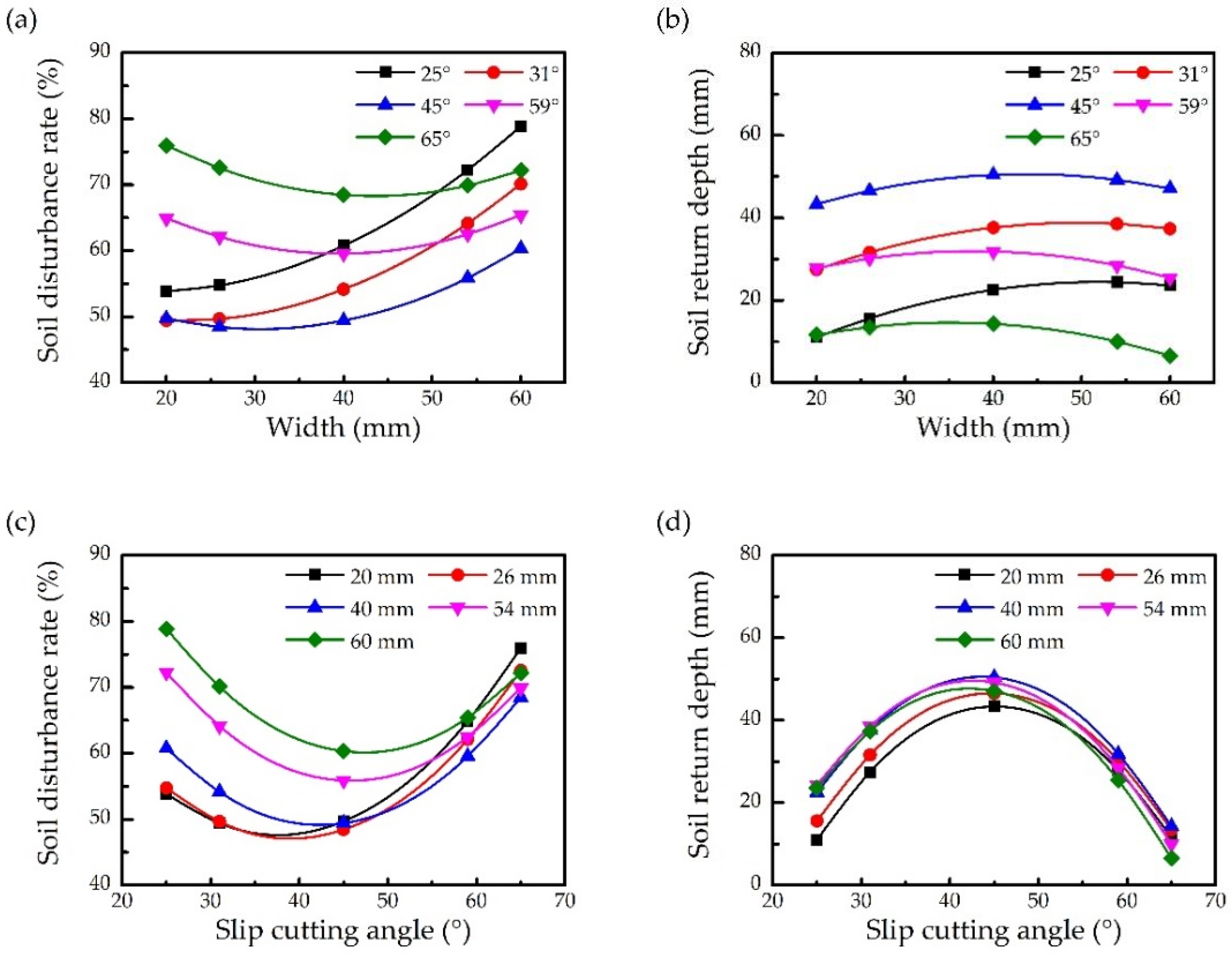
  • Soil disturbance rate ρ
The soil disturbance rate ρ is an important indicator of the soil disturbance behavior of the furrow opener. The larger the disturbance rate is, the more disturbed soil is during the operation. Disturbance rate ρ refers to the ratio of the disturbed soil area in the furrow contour multiplied by the width and depth of the gully, as shown in Figure 5; the soil disturbance rate is calculated according to Equation (1).
ρ = (A1 + A2)/dh × 100%
  • Soil-return depth h
Soil-return depth is an important indicator of the soil return performance of the furrow opener. The higher the soil-return depth h, the more superior the soil return performance of the furrow opener.

2.2. Soil Bin Verification and Performance Test

In order to verify the accuracy of the DEM virtual simulation parameter setting and the rationality of the structure optimization of the high-efficiency soil-returning liquid-fertilizer deep-application furrow opener, this study was conducted in May 2021 in the Agricultural Tools and Soil Bin Laboratory of Northeast Agricultural University (126°43′25″ N, 45°44′27″ E). Taking the operating speed of the high-efficiency soil-returning liquid fertilizer deep application furrow opener as the experimental factor, it was set to six levels of 0.2, 0.4, 0.6, 0.8, 1.0 and 1.2 m s−1 to verify the accuracy of the DEM virtual simulation model. The performance test of the furrow opener was carried out to examine the influence of the operating speed of the furrow opener on its soil disturbance behavior and soil return performance.
Before the test, the organisms, weeds and large clods in the soil were removed by a round-hole sieve. According to the actual situation in the field, the soil was sprayed with water, the soil’s moisture content was adjusted, and a ridge platform was built. The soil conditions and parameter indicators are shown in Figure 6a. The test was carried out under the condition of an 80 mm operating depth and 1 m s−1 operating speed. The test equipment comprised a soil bin trolley, a high-speed camera, a frequency conversion cabinet (model F1000-G055T3C, Yantai Ougri Transmission Electric Co., Ltd., Yantai, China) and a three-phase asynchronous motor (model Y2-10L2-4, Shanghai Yongce Machinery Equipment Co., Ltd., Shanghai, China), as shown in Figure 6b. The high-speed camera system captures the soil disturbance behavior of the furrow opener and records it by using supporting software. After the furrow opener operation, outer-layer gullies were delineated, and the gullies were delineated a second time after loose soil was removed with a brush. The results of the two depictions were combined as the extraction results of furrow contour parameters under this operating conditions, and relevant parameters were obtained. The test process is shown in Figure 6c.

3. Results

As shown in Figure 7a,b, when the slip cutting angle is fixed and the slip cutting angle is less than 59°, the soil disturbance rate increases with the increase in the furrow opener’s width. When the slip cutting angle is less than 59°, the soil disturbance rate first decreases and then increases with the increase in the furrow opener’s width. As the width of the furrow opener increases, the soil-return depth first increases and then decreases. As shown in Figure 7c,d, when the width of the furrow opener is fixed, the soil disturbance rate first decreases and then increases, and the soil-return depth first increases and then decreases. Equations (2) and (3) are obtained using Design-Expert 8.0.6 software. The factors of width x1 and the slip cutting angle x2 have significant effects on soil disturbance rate ρ and soil-return depth h, and the p values of the out-of-fit test item of the two regression models are all greater than 0.1; the regression model is shown in Table 2.
The above test results show that both regression models can solve the optimal solution of the parameters. Using the Design-Expert software, the minimum soil disturbance rate and maximum soil-return depth were taken as solving conditions to obtain the optimal solution parameter combination: the slip cutting angle is 43.27°, the width is 37.52 mm, the soil disturbance rate is 50.23%, and the soil-return depth is 50.9 mm. According to the optimization results, the virtual simulation verification shows that the soil disturbance rate is 51.81%, and the soil-return depth is 52.1 mm, which is basically consistent with the optimization results.
ρ = 97.079 − 0.0448x1 − 2.507x2 − 0.018x1x2 + 0.014x12 + 0.038x22
h = −146.683 + 1.629x1 + 7.434x2 − 0.011x1x2 − 0.013x12 − 0.08x22

3.1. Soil Bin Verification Test Results

In order to verify the accuracy of the parameter setting of the DEM virtual simulation model and the rationality of the structure optimization of the high-efficiency soil-returning liquid-fertilizer deep-application furrow opener, the soil bin verification test was carried out at a depth of 80 mm and an operating speed of 1.0 m s−1, and the test was repeated for three groups. Take the average value as the test result, and extract the furrow contour after the operation of the high-efficiency soil-returning liquid-fertilizer furrow opener. The obtained soil disturbance rate and soil-return depth parameter results are compared, as shown in Table 3.
The soil disturbance rates in the virtual simulation and soil bin verification tests are 52.81% and 50.37%, respectively. The soil-return depths are 50.8 and 52.7 mm. The relative errors are 5.45%, 4.68%, 3.61% and 4.84%. The results of the DEM virtual simulation and the soil bin verification test are consistent.
Soil disturbance behavior in the operation of high-efficiency soil-returning liquid-fertilizer furrow opener is captured by a high-speed camera, and a group of high-speed camera photos was randomly selected for qualitative comparison and analysis with the DEM virtual simulation test, as shown in Figure 8. Figure 8a shows the soil disturbance behavior of the high-efficiency soil-returning liquid-fertilizer deep-application furrow opener in the DEM virtual simulation test, in which the color of soil particles changes from red to blue as the speed decreases. The results show that when the furrow opener is working, the soil on both sides of the disturbed soil surface behaves in a lateral throwing manner, and the soil in the forward direction exhibits lifting and throwing relative to the negative direction.
Figure 8b shows the soil disturbance behavior of the high-efficiency soil-returning liquid-fertilizer deep-application furrow opener in the soil bin verification test. The dark area is the area with high soil-particle velocity, and the bright area is the area with low soil-particle velocity. The color on both sides of the disturbed soil surface in the figure is extremely dark, and it gradually becomes brighter from the inside to the outside, indicating that the soil in this area exhibits lateral throwing movements. The soil in the direction of operation changes from dark to bright from the bottom to the top and from the front to the back, indicating that the soil is lifted and broken by disturbances and flows in the opposite direction of the operation along the furrow opener’s surface.

3.2. Soil Bin Verification Test Results

Taking the operating speed as the test factor, the soil bin performance test was carried out to examine the influence of the operating speed of the furrow opener on its soil disturbance behavior and soil return performance. The soil disturbance behavior of the furrow opener during operations and the soil disturbance rate and soil return performance after operation were qualitatively analyzed at different operating speeds. The test results are shown in Figure 9a,b.
The soil-return depth first increases and then decreases with the increase in working speed. When the working speed is in the range of 0.4–1.0 m s−1, the soil’s return depth is relatively high, and the maximum and minimum soil-return depths reach 55.8 and 52.1 mm, respectively. In the range of 0.2~0.4 m s−1, the soil’s return depth is low.

4. Discussion

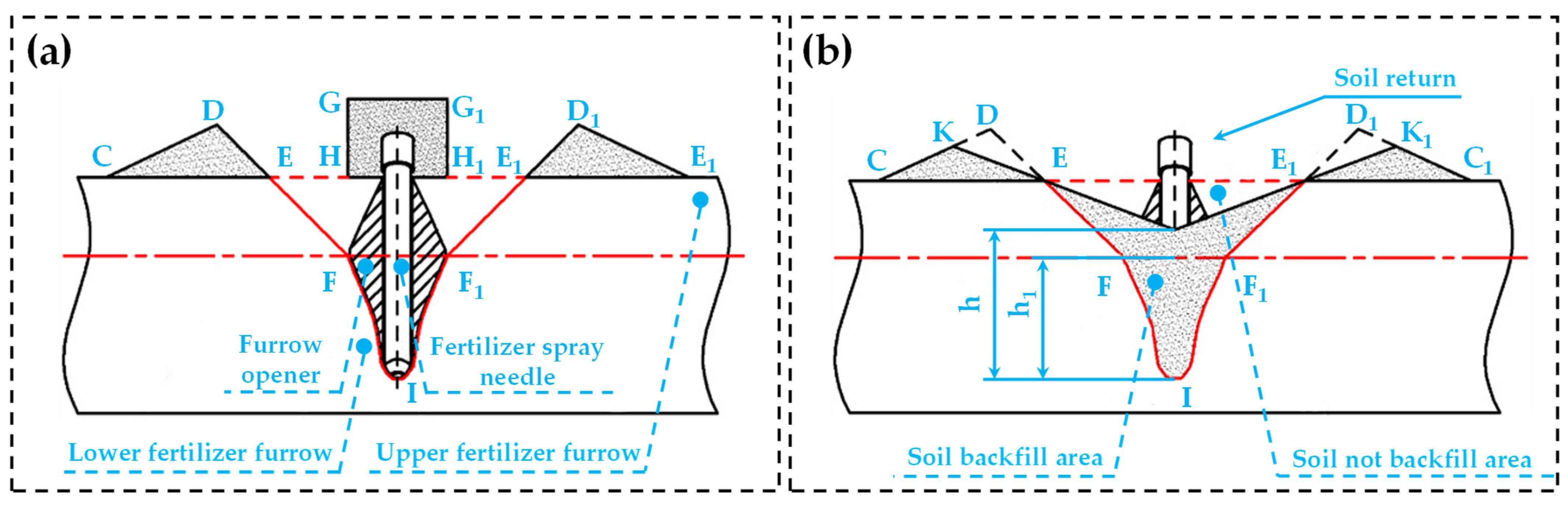
4.1. Analysis of Soil-Returning Behavior of High-Efficiency Soil-Returning Liquid Fertilizer Deep Application Furrow Opener

The furrow opener disturbs the soil during operation; it is completely buried in the soil, which produces disturbance behaviors for the soil, including lifting and breaking, lateral throwing and squeezing of the soil [28]. The squeezing of the soil affects the width below the furrowing contour, while lifting and breaking and lateral throwing determine the lateral throwing width and soil backfill rate. The behavior of soil disturbance is analyzed when the furrow opener is completely buried in the soil, as shown in Figure 10a. CDE and C1D1E1 are the cross-sections of the furrow and ridge formed by the lateral throwing of soil, GG1H1H is the upwardly lifted and broken soil, and EE1I is the cross-section of the fertilizer furrow. During the furrow opener’s operation, the fertilizer furrow is divided into upper and lower fertilizer furrows, which are the EE1F1F and F1FI areas, respectively. The soil in the EE1F1F area is lifted and laterally thrown to form the upper fertilizer furrow, and the soil in the F1FI area is extruded to form the lower fertilizer furrow. In this process, the soil volume is conserved; thus, the cross-sectional area of soil is conserved [29], and the cross-sectional area of soil after disturbance should satisfy the following:
SEE1F1F = SCDE + SC1D1E1 + SGC1H1H
where SEJE1I is the cross-sectional area of soil in the backfill area, mm2. SKDE and SK1D1E1 are the cross-sectional areas of the falling soil after being laterally thrown, mm2.
The soil disturbance behavior of the furrow opener is inevitable. The fallback soil is mainly observed in EE1F1F, DKE and D1K1E1 regions [8], and the filled area is mainly the F1FI region of the lower fertilizer furrow. When the soil’s return depth h is higher than the depth h1 of the lower fertilizer furrow (that is, h > h1) the furrow opener realizes the soil’s return function.

4.2. Disturbed Surface Analysis

The main function of the disturbed soil surface is to break the soil and promote the falling back of soil into the furrow. The disturbed soil surface of the furrow opener with the wedge-shaped surface structure [30] is shown in Figure 11, and the LL1 spacing is width l. The dynamic analysis of a single soil particle on the disturbed soil is describes as follows:
{ F N y + f y z sin β 2 f x y = m a y F N z m g f y z cos β 2 = m a z F = ( F N z 2 + F N y 2 + F N z 2 ) 1 2 f x y = tan φ sin α 2 ( F N z 2 + F N y 2 ) 1 2
where F is the resultant force of soil particles on the disturbed soil surface, N. FNy is the component force of the resultant force on the soil particle in the y direction, N. FNz is the component force of the resultant force on the soil particle in the x direction, N. fyz is the friction force of soil particles in the yOz plane, N. ay is the acceleration of soil particles in the y direction on the disturbed soil’ surface, m s2. az is the acceleration of soil particles in the z direction on the disturbed soil surface, m s2.
Arrange Equation (5) to obtain the following.
{ a y = F ( cot α 2 tan φ ) ( 1 + cot 2 β 2 + tan 2 α 2 ) 1 2 m 1 a z = F ( tan β 2 tan φ ) ( 1 + cot 2 β 2 + tan 2 α 2 ) 1 2 m 1
It can be seen from Equation (6) that acceleration ay in the y direction and acceleration az in the z direction are related to angle α and angle β, and angle α and angle β are related to width l. When the width increases, angle α and angle β increase, the acceleration ay in the y direction decreases, the acceleration az in the z direction increases, the lateral extrusion force of the disturbed soil surface on the soil decreases, and the breaking force on the upper soil layer increases, which is conducive to breaking the soil.
The kinematic analysis of soil particles on the disturbed soil surface is carried out, as shown in Figure 11b. Soil particles on the disturbed soil surface can be approximately regarded as oblique throwing motions [31]. v0 is the initial velocity of oblique throwing motion and y′ is the horizontal displacement of oblique throwing motion. The oblique throwing equation of soil particles is shown in Equation (7).
y = v 0 2 sin β 2 g 1
The larger the width l, the larger the angle β, and the better the effect of disturbed soil surface on soil loosening and breaking, but the lateral throwing displacement y′ of soil particles increases accordingly, which is difficult for the thrown soil to fall back. When α = β = 90°, ay = az and FNy = FNz, the extruding and breaking effects of disturbed soil surface are consistent. When the width continues to increase, as width l increases, the amount of externally thrown soil and externally throwing horizontal displacement continues to increase, which is likely to cause a decrease in the amount of returned soil. At the same time, the soil disturbance behaviors on the disturbed soil’s surface mainly include breaking and lateral throwing, and with the increase in the furrow’s width and the amount of lateral throwing soil, the cross-sectional area of the furrow contour increases. According to the soil disturbance rate equation, the cross-sectional area of the furrow contour increases and the soil disturbance rate increases.

4.3. Guide Inclined Surface Analysis

The guide inclined surface is used to guide the loose and broken soil to fall back into the fertilizer furrow. The soil flows to the tail of the furrow opener along the guided inclined surface and finally falls into the fertilizer spray needle to achieve falling soil and burial of the fertilizer. The structure of the guided inclined surface is shown in Figure 12.

4.4. Analysis of Extruded Soil Surface

The extruded soil surface is mainly used to push the soil during the operation of the furrow opener to form a fertilizer furrow. The structure of the extruded soil surface is shown in Figure 13.

4.5. Analysis of Shaping Surface

The shaping surface extrudes the soil so as to achieve the purpose of shaping the fertilizer furrow and the furrow wall. The structure diagram of the shaping surface is shown in Figure 14a. The dynamics and force analysis of a single soil particle on the shaping surface are shown in Figure 14b,c.
The dynamic equations of a single soil-particle column along x, y and z directions on the shaping surface are described as follows:
{ F N x + f x y cos γ 2 = m a x F N y + f y z f x y = m a y F N z + f y z sin γ 2 + m g = m a z F = ( F N x 2 + F N y 2 + F N z 2 ) 1 2 f x y = tan φ sin δ ( F N x 2 + F N y 2 ) 1 2 f y z = tan φ sin γ 2 ( F N y 2 + F N z 2 ) 1 2
where F is the resultant force on the shaping surface of soil particles, N. fxy is the component force of fxy in the y direction, N. fyz is the component force of fyz in the y direction, N. δ is the angle between the shaping surface and the x-axis, (°).
Sort Equation (8).
{ a x = F N x ( tan δ + tan φ ) ( 1 + cot 2 γ 2 + tan 2 δ ) 1 2 m 1 a y = F N y [ 1 + tan φ ( cot γ 2 tan δ ) ] ( 1 + cot 2 γ 2 + tan 2 δ ) 1 2 m 1 a z = F N z ( cot γ 2 tan φ ) ( 1 + cot 2 γ 2 + tan 2 δ ) 1 2 m 1 + g
It can be seen from Equation (9) that pressures FNy and FNz in the horizontal and vertical directions of the soil on the shaping surface play a major role in shaping the furrow wall, and they are only related to angles γ and δ, which are determined by the width; thus, the operating performance of the shaping surface is related to the width. When the width increases, ay and az increase. The horizontal and vertical pressures FNy and FNz of the shaping surface on soil increase, and the downward extruding ability of the shaping surface on soil increases. However, with the increase in width, the extrusion of the furrow opener’s shaping surface on the soil is intensified, resulting in a furrow shape that is too wide and the soil is unable to bury the fertilizer well.

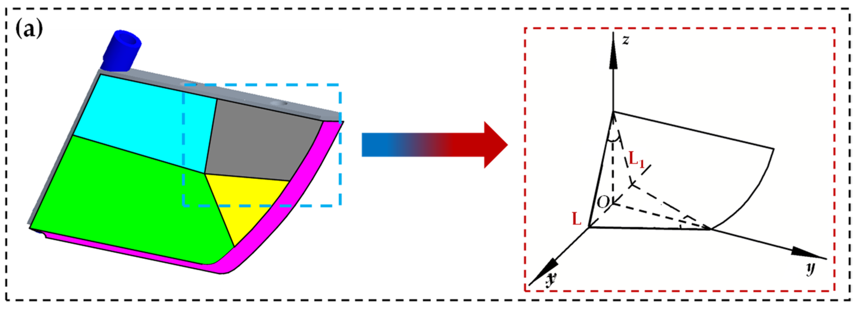
4.6. Analysis of Sliding–Cutting Edge

The high-efficiency soil-returning liquid fertilizer furrow opener cuts the soil by the sliding–cutting edge. During the sliding and cutting process, the soil is extruded by the sliding–cutting edge until the soil stress reaches the failure limit and shear fracture occurs [32]. The dynamics analysis of soil particle M on the xOz plane is carried out, as shown in Figure 15.
In Figure 15, the particle’s dynamics equations of particle M along the τ direction (tangential direction) and the n direction (normal direction) are as follows:
{ F N s F f x cos θ F f z sin θ = m a e cos θ F s τ F f x sin θ F f z cos θ = m ( a e sin θ a r ) F s τ = F s n tan φ
where m is the mass of the soil particle M, kg. θ is the slip cutting angle, °. φ is the soil friction angle, °. ar is the relative acceleration of the soil particle M, m/s2. ae is the involved acceleration of the soil particle M, m/s2. Fsn is the positive pressure on the soil particle M, N. F is the tangential force on the soil particle M, N. Ffx is the component force along the x-axis of the resistance given to the soil particle M by the surrounding soil on the xOy plane, N. Ffz is the component force along the y-axis, N, of the resistance given by the soil particle M by the surrounding soil in the xOy plane.
Simplify Equation (10) to obtain the following.
F s n ( tan θ tan φ ) F f z sin 2 θ = m a r
From Equation (11), it can be seen that when the slip cutting angle is greater than the soil‘s friction angle (that is, θ > φ), the relative acceleration of the particle is ar > 0, and the sliding–cutting edge produces sliding–cutting actions on the soil [32]; the larger the slip cutting angle, the stronger the sliding–cutting action of the sliding–cutting edge on the soil [33]. For the convenience of analysis, θ1 on the sliding–cutting edge in Figure 16 is defined as the initial slip cutting angle, and θ2 is the terminational slip cutting angle. There is always θ1 < θ < θ2 on the sliding–cutting edge. When the initial slip cutting angle θ1 is determined, the larger the terminational slip cutting angle θ2, the larger slip cutting angle θ anywhere on the sliding–cutting edge, and the larger the terminational slip cutting angle θ2, the stronger the sliding–cutting action of the sliding–cutting edge on the soil [34]. The shape of the sliding–cutting edge is a parabola AB, as shown in Figure 17.
The equation of the sliding–cutting curve AB is defined as follows.
z = a x 2
The equation of the sliding–cutting curve AB is defined as follows.
{ z A = tan ( π 2 θ 1 ) = 2 a x 1 z B = tan ( π 2 θ 2 ) = 2 a x 2
The equation of the parabola AB is defined as follows.
z = ( cot θ 1 cot θ 2 ) x 2 z AB 1
It can be seen from Equation (14) that the shape of the sliding–cutting curve is jointly determined by the initial slip cutting angle θ1, the terminational slip cutting angle θ2 and the furrow opener height zAB. The kinematics analysis of soil particles at different terminational slip cutting angles is carried out, as shown in Figure 17b. The black-line terminational slip cutting angle is θ2, which is smaller than the red-line terminational slip cutting angle θ2. Set the furrow opener operating at speed v and calculate the movement path of soil particles on the furrow opener after it advances at a certain distance.
S θ 2 = x 2 x 4 [ ( cot θ 1 cot θ 2 2 ) 1 2 z AB 1 2 ] x d x
S θ 2 = x 3 x 4 [ ( cot θ 1 cot θ 2 2 ) 1 2 z AB 1 2 ] x d x
Simplify the above equation as follows.
S θ 2 = 2 3 ( 1 + cot θ 1 cot θ 2 z AB ) ( x 4 3 2 x 2 3 2 )
S θ 2 = 2 3 ( 1 + cot θ 1 cot θ 2 z AB ) ( x 4 3 2 x 3 3 2 )
From Equations (17) and (18), the sliding distance s of soil particles along the sliding–cutting edge is determined by the terminational slip cutting angle θ2. When the furrow opener operates at speed v and travels through a certain operating stroke, if the slip cutting angle θ2 is larger, the soil particles will slide rapidly along the sliding–cutting edge [34], and the soil will quickly move along the sliding–cutting edge to the part with larger slip cutting angle.
During the operation of the furrow opener, the soil on which the sliding–cutting edge acts is a deformed body, and the stress situation is relatively complex; thus, a material mechanics method is used for analysis, as shown in Figure 17.
Since the sliding–cutting edge is a symmetrical structure, only one side of the sliding–cutting edge is needed for mechanical analysis. When the sliding–cutting edge interacts with the soil, the extrusion force of the soil on the sliding–cutting edge comes from normal stress, and the resistance of the furrow opener comes from the shear stress, as shown in Figure 17a. According to the mechanics of materials, the integral of the stress on the contact area between the sliding–cutting edge and the soil is the force on the sliding–cutting edge, as shown in Equation (19):
{ F N = σ d S F f = τ d S
where S is the contact area between the sliding–cutting edge and soil, mm2.
The contact surface between the sliding–cutting edge and the soil is a curved surface, and directly calculating the contact area is difficult. Therefore, the contact area and the extruded soil volume between the sliding–cutting edge and the soil are calculated by integration, as shown in Figure 17b, and the calculation of the contact area is shown in Equation (20).
S = 0 y 1 { 0 x 1 1 cos θ 2 [ 1 + ( cot θ 1 cot θ 2 2 z AB x ) 2 d x ] 1 2 } d y = 1 cot 2 θ 1 + cot 2 θ 2 2 cot 2 θ 1 sin θ 2 { x 1 2 ( 1 + cot θ 1 cot θ 2 4 z 2 AB x 1 2 ) + ln [ x + ( 1 + cot θ 1 cot θ 2 4 z 2 AB x 1 2 ) ] }
S is the contact area between the sliding–cutting edge and the soil. It can be seen that the larger the terminational slip cutting angle θ2, the larger the contact area between the sliding–cutting edge and the soil, and the greater the extrusion force of the sliding–cutting edge on the soil and, thus, the greater the resistance from the soil, which indicates that the terminational slip cutting angle is the main factor affecting the extruding effect of the sliding–cutting edge on the soil. In order to quantify the degree of soil extrusion by the sliding–cutting edge, an integral equation is used to calculate the amount of soil extrusion.
V = 0 y 1 [ 0 x 1 cot θ 1 cot θ 2 z AB x 2 d x ] d y = cot θ 1 cot θ 2 3 z AB x 1 3 y 1
According to Equation (21), it can be seen that as the terminational slip cutting angle θ2 increases, the amount of soil extruded by the sliding–cutting edge increases. To sum up, the terminational slip cutting angle θ2 is an important factor affecting the operating performance of the sliding–cutting edge. The increase in the terminational slip cutting angle θ2 increases the cutting ability of the sliding–cutting edge on soil, but at the same time, it will increase the resistance of the furrow opener and cause the soil to rapidly flow to the sliding–cutting edge with a larger slip cutting angle, resulting in soil accumulation. At this time, the sliding–cutting edge severely extrudes the soil, and then the soil is compressed and bonded. the amount of broken soil is reduced, and the soil’s return performance worsens. According to the research of Zhao et al. [35], when the value of the terminational slip cutting angle θ2 is between 35 and 55°, improving the soil’s breaking performance of the sliding–cutting edge and improving the soil’s return performance of the furrow opener are beneficial. When increasing the terminational slip cutting angle, the sliding–cutting effect of the sliding–cutting edge on the soil is enhanced, the soil has better fluidity on the surface of the sliding–cutting edge, the degree of soil extrusion is lighter, and the cross-sectional area of the furrow contour is small. According to the soil disturbance rate equation, the soil’s disturbance rate does not change significantly. When the terminational slip cutting angle is too large, the sliding–cutting edge mainly pushes the soil; a large amount of soil flows rapidly to the part with a larger slip cutting angle, and soil accumulation occurs at the terminational slip cutting angle. The soil is extruded during the operation of the furrow opener, which results in soil compression. The amount of broken soil decreases, the cross-sectional area of the furrow contour increases, and the soil disturbance rate increases rapidly.

4.7. Analysis of Furrow Contour Parameter Results in Soil Bin Verification Test

The test results of the virtual simulation and the soil bin verification tests are basically the same, but the maximum lateral throwing soil width and furrow width in the soil bin verification test are slightly smaller than those of the virtual simulation, and the soil-return depth is slightly higher than that of the virtual simulation. The reason is that the volume and mass of soil particles in the virtual simulation is larger than that of actual soil particles, which affects the particle’s movement behavior during virtual simulation operation, resulting in parameter differences [36,37,38].

4.8. Analysis of High-Speed Camera Results of Soil Bin Verification Test

Based on the qualitative comparison and analysis of the soil disturbance behavior of the two, it can be seen that, under the same conditions, the particle’s velocity area formed during the operation of high-efficiency soil-returning liquid-fertilizer furrow opener is basically the same, and the soil disturbance behavior and soil movement state of the furrow opener are basically the same. The parameter settings in the EDEM virtual simulation are more accurate [39].

4.9. Analysis of Soil Bin Performance Test Results

When the operating speed is low, the soil is compressed and bonded by the extruding action of the furrow opener, and the amount of broken soil is small, and the depth of soil return is low. When the speed is too high, the soil’s return depth decreases sharply. The reason is that the high operating speed accelerates the soil disturbance behavior of the furrow opener and increases the amount of soil thrown out, leading to a difficulty in the soil’s ability to fall back, and the soil’s return depth decreases.

5. Conclusions

We found that the key parameters of the high-efficiency soil-returning liquid-fertilizer deep-application furrow opener with low disturbance and high soil return include the width and slip cutting angle, which have significant impacts on the soil’s return rate and soil-return depth. The parameter combination suitable for the cold region of Northeast China is a slip cutting angle of 43.27° and a width of 37.52 mm.
Under the optimal combination of structural parameters, the soil disturbance rate of the high-efficiency soil-return liquid-fertilizer opener is 50.23% and the soil-return depth is 50.9 mm. According to the virtual simulation verification of the optimized results, the soil disturbance rate is 51.81% and the soil-return depth is 52.6 mm, which is basically consistent with the optimized results.
The interaction process of the sliding–cutting edge soil, wedge surface soil and the mechanical and kinematic models of the furrow opener constructed by us can provide a theoretical basis for the design of future furrow openers. The qualitative and quantitative analyses of soil disturbance behaviors and soil-return performance of the high-efficiency return liquid-fertilizer opener at different forward speeds (0.2, 0.4, 0.6, 0.8, 1.0 and 1.2 m s−1) of the opener were conducted. The qualitative analysis showed that the soil disturbance behavior of the opener gradually intensified with the increase in forward speed, and the soil’s return performance was first enhanced and then weakened with the increase in forward speed, and the appropriate soil disturbance behavior can, to a certain extent, promote the soil’s return performance of the high-efficiency soil return liquid-fertilizer opener. The quantitative analysis showed that the soil disturbance rate ρ was moderate in the speed range of 0.4–1.0 m s−1, and the minimum and maximum values of soil-return depth h reached 52.1 mm and 55.8 mm, respectively, which both met the design requirements of the high-efficiency soil-return liquid-fertilizer opener.
We only conducted experiments and studies on soil conditions in the cold region of Northeast China, and further studies on soil applicability in other regions are needed.

Author Contributions

Conceptualization, W.Z.; software, C.S. and X.S.; validation, Z.L.; formal analysis, X.N. and K.S.; resources, Y.J.W.; data curation, L.T.; writing—original draft preparation, W.Z.; writing—review and editing, Y.J.W.; supervision, Y.J.W.; project administration, Y.J.W.; funding acquisition, Y.J.W. All authors have read and agreed to the published version of the manuscript.

Funding

This research was financially supported by the Natural Science Foundation of China (Grant No. 51905086), China Postdoctoral Science Foundation Funded Project (Grant No. 2019M66124), Heilongjiang Postdoctoral Science Foundation Specially Funded Project (Grant No. LBH-Z19044), and Heilongjiang Province General Undergraduate Higher Education Institution Young Innovative Talents Training Program (UNPYSCT-2020100).

Institutional Review Board Statement

Not applicable.

Data Availability Statement

Not applicable.

Acknowledgments

The authors would like to thank their schools and colleges, as well as the funding providers of the project. All support and assistance are sincerely appreciated.

Conflicts of Interest

The authors declare no conflict of interest.

Nomenclature

LThe opener width (mm)
θThe slip cutting angle (°)
θ1The initial slip cutting angle (°)
θ2The larger the terminational slip cutting angle θ2 (°)
φThe soil friction angle (°)
ρThe soil disturbance rate (%)
hThe higher the soil-return depth (mm)

References

  1. Sun, B.; Jia, S.; Zhang, S.; McLaughlin, N.B.; Zhang, X.; Liang, A.; Chen, X.; Wei, S.; Liu, S. Tillage, seasonal and depths effects on soil microbial properties in black soil of Northeast China. Soil Tillage Res. 2016, 155, 421–428. [Google Scholar] [CrossRef]
  2. Zhang, S.; Chen, X.; Jia, S.; Liang, A.; Zhang, X.; Yang, X.; Wei, S.; Sun, B.; Huang, D.; Zhou, G. The potential mechanism of long-term conservation tillage effects on maize yield in the black soil of Northeast China. Soil Tillage Res. 2015, 154, 84–90. [Google Scholar] [CrossRef]
  3. Qu, Y.; Pan, C.; Guo, H. Factors Affecting the Promotion of Conservation Tillage in Black Soil—The Case of Northeast China. Sustainability 2021, 13, 9563. [Google Scholar] [CrossRef]
  4. Liu, Q.; Wu, K.; Song, W.; Zhong, N.; Wu, Y.; Fu, X. Improving crop nitrogen use efficiency toward sustainable green revolution. Annu. Rev. Plant Biol. 2022, 73, 523–551. [Google Scholar] [CrossRef] [PubMed]
  5. Pimentel, D. Green revolution agriculture and chemical hazards. Sci. Total Environ. 1996, 188, S86–S98. [Google Scholar] [CrossRef]
  6. Han, T.; Jinwu, W.; Changsu, X.U.; Wenqi, Z.; Jinfeng, W.; Xiu, W. Research progress analysis on key technology of chemical fertilizer reduction and efficiency increase. Nongye Jixie Xuebao/Trans. Chin. Soc. Agric. Mach. 2019, 50, 1–19. [Google Scholar]
  7. Shi, C.L.; Li, Y.; Zhu, J.F. Rural labor transfer, excessive fertilizer use and agricultural non-point source pollution. J. China Agric. Univ. 2016, 21, 169–180. [Google Scholar]
  8. Zhu, L.Z.; Qiu, J.; Fang, X. Soil conservation measures and enlightenment in foreign countries. Soil Fertil. Ences China 2015, 2, 1–4. [Google Scholar]
  9. Chen, Y.; Zhang, Q.; Petkau, D.S. Evaluation of different techniques for liquid manure application on grassland. Appl. Eng. Agric. 2001, 17, 489. [Google Scholar] [CrossRef]
  10. Swanepoel, P.A.; Labuschagne, J. Canola is injured by in-row nitrogen placement associated with disc openers, but not by tine openers. Crop Sci. 2020, 60, 466–474. [Google Scholar] [CrossRef]
  11. Xie, J.S.; Yang, Y.S.; Chen, G.S.; Zhu, J.M.; Zeng, H.D.; Yang, Z.J. Effects of vegetation restoration on water stability and organic carbon distribution in aggregates of degraded red soil in subtropics of China. Acta Ecol. Sin. 2008, 28, 702–709. [Google Scholar]
  12. Zhang, L.; He, Y.; Yang, H.; Tang, Z.; Zheng, X.; Meng, X. Analysis of the relationship between the development of liquid fertilizer machinery and modern agriculture. J. Chin. Agric. Mech. 2021, 42, 34–40. [Google Scholar]
  13. Wenqi, Z.; Hong, X.; Ziming, L.I.U.; Jinwu, W.; Huinan, H.; Aoxue, W. Design and Test of SYJ-3 Deep Application-type Inclined Liquid Fertilizer Hole Applicator. Nongye Jixie Xuebao/Trans. Chin. Soc. Agric. Mach. 2020, 51, 78–86. [Google Scholar]
  14. Wang, J.; Wen, N.; Liu, Z.; Zhou, W.; Tang, H.; Wang, Q.; Wang, J. Coupled Bionic Design of Liquid Fertilizer Deep Application Type Opener Based on Sturgeon Streamline to Enhance Opening Performance in Cold Soils of Northeast China. Agriculture 2022, 12, 615. [Google Scholar] [CrossRef]
  15. Wang, J.; Pan, Z.; Zhou, W.; Wang, J.; He, J.; Lang, C. Design and test of SYJ-2 type liquid variable fertilizer. Trans. Chin. Soc. Agric. Mach. 2015, 46, 53–58. [Google Scholar]
  16. Godwin, R.J.; Spoor, G. Soil failure with narrow tines. J. Agric. Eng. Res. 1977, 22, 213–228. [Google Scholar] [CrossRef]
  17. Godwin, R.J. A review of the effect of implement geometry on soil failure and implement forces. Soil Tillage Res. 2007, 97, 331–340. [Google Scholar] [CrossRef]
  18. Solhjou, A.; Desbiolles, J.M.; Fielke, J.M. Soil translocation by narrow openers with various blade face geometries. Biosyst. Eng. 2013, 114, 259–266. [Google Scholar] [CrossRef]
  19. Rodhe, L.; Etana, A. Performance of slurry injectors compared with band spreading on three Swedish soils with ley. Biosyst. Eng. 2005, 92, 107–118. [Google Scholar] [CrossRef]
  20. Shuhong, Z.; Hongjun, L.; Hewen, T. Design and performance experiment of opener based on bionic sailfish head curve. Trans. Chin. Soc. Agric. Eng. 2017, 33, 32–39. [Google Scholar]
  21. Beyaz, A.; Gerdan, D. Computer-aided Stress Analysis of a Model of Tractor Mounted Auger Drill. Agric. Sci. Dig.-A Res. J. 2019, 39, 90–95. [Google Scholar] [CrossRef] [Green Version]
  22. Bravo, E.L.; Tijskens, E.; Suárez, M.H.; Cueto, O.G.; Ramon, H. Prediction model for non-inversion soil tillage implemented on discrete element method. Comput. Electron. Agric. 2014, 106, 120–127. [Google Scholar] [CrossRef]
  23. Mak, J.; Chen, Y.; Sadek, M.A. Determining parameters of a discrete element model for soil–tool interaction. Soil Tillage Res. 2012, 118, 117–122. [Google Scholar] [CrossRef]
  24. Topp, G.C.; Parkin, G.W.; Ferré, T.P.A.; Carter, M.R.; Gregorich, E.G. Soil water content. In Soil Sampling and Methods of Analysis; Canadian Society of Soil Science: Pinawa, MB, Canada, 2008; pp. 939–962. [Google Scholar]
  25. Li, J.; Tong, J.; Hu, B.; Wang, H.B.; Mao, C.Y.; Ma, Y. Calibration of parameters of interaction between clayey black soil with different moisture content and soil-engaging component in northeast China. Trans. CSAE 2019, 35, 130–140. [Google Scholar]
  26. Tian, X.; Cong, X.; Qi, J.; Guo, H.; Li, M.; Fan, X. Parameter Calibration of Discrete Element Model for Corn Straw-Soil Mixture in Black Soil Areas. Trans. Chin. Soc. Agric. Mach. 2021, 52, 100–108+242. [Google Scholar]
  27. Zhao, J.; Wang, X.; Zhuang, J.; Liu, H.; Wang, Y.; Yu, Y. Coupled Bionic Design Based on Primnoa Mouthpart to Improve the Performance of a Straw Returning Machine. Agriculture 2021, 11, 775. [Google Scholar] [CrossRef]
  28. Liu, H.; Han, J.; Chen, J.; Lv, J.; Zhao, S. Performance simulation and experiment on rigid press wheel for hilly area. Nongye Jixie Xuebao/Trans. Chin. Soc. Agric. Mach. 2018, 49, 114–122. [Google Scholar]
  29. Shuhong, Z.; Hewen, T.; Jiayi, W. Design and experiment of multifunctional integrated seeding opener. Trans. Chin. Soc. Agric. Eng. (Trans. CSAE) 2018, 34, 58–67. [Google Scholar]
  30. Xiaodong, Y. The Theory Analysis of Furrower Soil Backfilling. Agric. Sci. Technol. Equip. 2014, 11, 37–39. [Google Scholar] [CrossRef]
  31. Jun, S. Simulation Study and Analysis of Materials Conveying Process by the Belt Conveyer Based on EDEM. Mech. Res. Appl. 2019, 32, 59–61. [Google Scholar] [CrossRef]
  32. Jia, H.; Zheng, J.; Yuan, H.; Guo, M.; Wang, W.; Jiang, X. Design and experiment of profiling sliding-knife opener. Trans. Chin. Soc. Agric. Eng. 2017, 33, 16–24. [Google Scholar]
  33. Barr, J.B.; Ucgul, M.; Desbiolles, J.M.A.; Fielke, J.M. Simulating the effect of rake angle on narrow opener performance with the discrete element method. Biosyst. Eng. 2018, 171, 1–15. [Google Scholar] [CrossRef]
  34. Jian, Z.; Honglei, J.; Yunhai, M. Design and experiment of sliding-knife-type disc opener. Trans. Chin. Soc. Agric. Mach. 2013, 44, 83–88. [Google Scholar]
  35. Zhao, S.; Liu, H.; Zhang, X.; Yang, Y.; Lü, B.; Tan, H. Design and optimization experiment of working performance of sliding push opener. Trans. Chin. Soc. Agric. Eng. 2016, 32, 26–34. [Google Scholar]
  36. Aikins, K.A.; Ucgul, M.; Barr, J.B.; Jensen, T.A.; Antille, D.L.; Desbiolles, J.M.A. Determination of discrete element model parameters for a cohesive soil and validation through narrow point opener performance analysis. Soil Tillage Res. 2021, 213, 105123. [Google Scholar] [CrossRef]
  37. Wang, Y.; Xue, W.; Ma, Y.; Tong, J.; Liu, X.; Sun, J. DEM and soil bin study on a biomimetic disc furrow opener. Comput. Electron. Agric. 2019, 156, 209–216. [Google Scholar] [CrossRef]
  38. Bai, H.; Li, S.; Wang, D.; Fang, X.; Niu, K.; Zhou, L.; Xiong, S.; Fan, C. Design and EDEM simulation of fertilizer stratification and deep application device. In Proceedings of the ASABE Annual International Meeting, American Society of Agricultural and Biological Engineers, Boston, MA USA, 7–10 July 2019; p. 1. [Google Scholar]
  39. Barr, J.; Desbiolles, J.; Ucgul, M.; Fielke, J.M. Bentleg furrow opener performance analysis using the discrete element method. Biosyst. Eng. 2020, 189, 99–115. [Google Scholar] [CrossRef]
Figure 1. Measurement process and equipment for measuring black soil physical parameters. (a) Measurement process and equipment for measuring black soil bulk density parameters. (b) Measurement process and equipment for measuring black soil moisture content. (c) Measurement process and equipment for measuring black soil shear modulus and Poisson’s ratio parameters.
Agriculture 12 01286 g001
Figure 2. Measurement process and equipment for measuring contact parameters of black soil and 65 Mn. (a) Measurement process and equipment for measuring rolling friction coefficient of black soil and 65 Mn material. (b) Measurement process and equipment for measuring collision recovery coefficient of black soil and 65 Mn material.
Agriculture 12 01286 g002
Figure 3. Measurement process and equipment of black soil stacking angle parameters. (a) Measurement process and equipment of real black soil stacking angle parameters. (b) Measurement process and equipment of black soil stacking angle parameters in DEM virtual simulation tests.
Agriculture 12 01286 g003
Figure 4. Construction and simulation process of the DEM virtual simulation model. (a) Construction of the DEM virtual simulation soil bin model. (b) Construction of the 3D model of high-efficiency soil-returning liquid-fertilizer deep-application furrow openers. (c) High-efficiency soil-returning liquid-fertilizer deep-application furrow opener and DEM virtual simulation test processes.
Agriculture 12 01286 g004
Figure 5. Schematic diagram of furrow contour section parameters.
Agriculture 12 01286 g005
Figure 6. Soil bin test process and equipment. (a) Soil conditions and indicators of the indoor soil bin test. (b) Relevant equipment related to the indoor soil bin test. (c) The extraction process and results of soil furrow contour parameters.
Agriculture 12 01286 g006
Figure 7. DEM virtual simulation test results. (a) The effect of the furrow opener’s width on soil disturbance rate. (b) The effect of the furrow opener’s width on soil-return depth. (c) The effect of slip cutting angle on soil disturbance rate. (d) The effect of the slip cutting angle on the soil-return depth.
Agriculture 12 01286 g007
Figure 8. Comparison of results between DEM virtual simulation test and soil bin test. (a) Comparison of furrow contour. (b) Comparison of soil disturbance rate.
Agriculture 12 01286 g008
Figure 9. Soil bin performance test results. (a) Effect of working speed on soil-disturbance rate. (b) Effect of working speed on soil-return depth.
Agriculture 12 01286 g009
Figure 10. Schematic diagram of soil-returning behavior of high-efficiency soil-returning liquid-fertilizer deep-application furrow opener. (a) Schematic diagram of soil disturbance behaviors. (b) Schematic diagram of the soil-return principle.
Agriculture 12 01286 g010
Figure 11. Schematic diagram of disturbed soil surface structure and kinematic analysis of soil particles. (a) Schematic diagram of disturbed soil surface structure. (b) Force analysis of soil particles. (c) Analysis of oblique throwing motion of soil particles.
Agriculture 12 01286 g011aAgriculture 12 01286 g011b
Figure 12. Schematic diagram of guide inclined surface structure.
Agriculture 12 01286 g012
Figure 13. Schematic diagram of the extruded soil surface structure.
Agriculture 12 01286 g013
Figure 14. Schematic diagram of the guide inclined surface structure. Schematic diagram of the shaping surface structure and soil particle kinematics analyses. (a) Schematic diagram of the disturbed soil surface structure. (b) Force analysis on the yOz plane. (c) Force analysis on the xOy plane.
Agriculture 12 01286 g014
Figure 15. Dynamics analysis of soil particles at the sliding–cutting edge.
Agriculture 12 01286 g015
Figure 16. Sliding–cutting curve and soil particle motion analysis. (a) Sliding–cutting curve. (b) Distance of soil particles moving along the sliding–cutting edge.
Agriculture 12 01286 g016
Figure 17. Analysis of the interaction between the sliding–cutting force and soil. (a) The force of the sliding–cutting edge. (b) The interaction analysis between the sliding–cutting edge and the soil.
Agriculture 12 01286 g017
Table 1. Parameters of DEM virtual simulation test model.
ParametersValues
Soil particle size (mm)2~3
Soil density (g·cm3)1.516
Soil Poisson’s ratio0.39
Soil shear modulus (MPa)1.00
Coefficient of static friction between soil particles0.53
Coefficient of dynamic friction between soil particles0.78
Recovery coefficient between soil particles0.23
surface energy density (J·m2)5.50
Soil−65 Mn static friction coefficient0.47
Soil−65 Mn rolling friction coefficient0.11
Soil−65 Mn collision recovery coefficient0.09
Table 2. Optimization model of test data.
ResourcesRegression Model on Slip Cut AngleRegression Model on Width
Sum of SquaresdfF-Valuep-ValueSum of SquaresdfF-Valuep-Value
Model259.19533.50<0.0001213.26524.88<0.0001
x1126.53181.77<0.000116.9919.910.0104
x225.30116.350.002310.5016.130.0328
x1x212.9618.380.01604.6212.700.1316
x1264.52141.70<0.000154.34131.690.0002
x2229.88119.310.0013126.80173.96<0.0001
Residual15.4710 17.1510
Lack of fit11.3036.310.02111.8830.290.8337
Pure error4.187 15.277
Cor total274.6715 230.4115
Table 3. Comparison of DEM virtual simulation test and soil bin test results.
Test FormNo.Soil Disturbance (%)Soil-Return Depth (mm)
DEM virtual simulation test152.8150.8
Soil bin test results150.1152.7
251.0753.3
349.9252.2
Average value50.3752.7
Publisher’s Note: MDPI stays neutral with regard to jurisdictional claims in published maps and institutional affiliations.

