Article

Single-Neuron PID UAV Variable Fertilizer Application Control System Based on a Weighted Coefficient Learning Correction

1
College of Information and Electrical Engineering, Shenyang Agricultural University, Shenyang 110866, China
2
Liaoning Engineering Research Center for Information Technology in Agriculture, Shenyang 110299, China
*
Authors to whom correspondence should be addressed.
Agriculture 2022, 12(7), 1019; https://doi.org/10.3390/agriculture12071019
Submission received: 20 June 2022 / Revised: 8 July 2022 / Accepted: 13 July 2022 / Published: 13 July 2022
(This article belongs to the Special Issue Application of UAVs in Precision Agriculture)

Abstract

:
Agricultural unmanned aerial vehicles (UAVs), which are a new type of fertilizer application technology, have been rapidly developed internationally. This study combines the agronomic characteristics of rice fertilization with weighted coefficient learning-modified single-neuron adaptive proportional–integral–differential (PID) control technology to study and design an aerial real-time variable fertilizer application control system that is suitable for rice field operations in northern China. The nitrogen deficiency at the target plot is obtained from a map based on a fertilizer prescription map, and the amount of fertilizer is calculated by a variable fertilizer application algorithm. The advantages and disadvantages of the two control algorithms are analyzed by a MATLAB simulation in an indoor test, which is integrated into the spreading system to test the effect of actual spreading. A three-factor, three-level orthogonal test of fertilizer-spreading performance is designed for an outdoor test, and the coefficient of variation of particle distribution Cv (a) as well as the relative error of fertilizer application λ (b) are the evaluation indices. The spreading performance of the spreading system is the best and can effectively achieve accurate variable fertilizer application when the baffle opening is 4%, spreading disc speed is 600 r/min, and flight height is 2 m, with a and b of evaluation indexes of 11.98% and 7.02%, respectively. The control error of the spreading volume is 7.30%, and the monitoring error of the speed measurement module is less than 30 r/min. The results show that the centrifugal variable fertilizer spreader improves the uniformity of fertilizer spreading and the accuracy of fertilizer application, which enhances the spreading performance of the centrifugal variable fertilizer spreader.

1. Introduction

Granular fertilizers, which are considered an effective method to provide adequate amounts of various nutrients during the reproductive cycle of high-yield crops such as rice, account for a large proportion of current agricultural production. The effective application of fertilizer can improve crop yield and quality, which plays an important role in food production security and agricultural efficiency [1,2]. Traditionally, uniform fertilizer application is used in the management of rice fields. However, ignoring significant differences in nutrient requirements and the practice of overfertilization both cause a reduction in crop yield [3]. Notably, inadequate fertilizer application limits the uptake of nutrients by crops, leading to poor quality [4,5,6,7]. Variable fertilizer application, which is one of the most effective methods for the rational distribution of fertilizer nutrients, is an important part of precision agriculture. Tractors and other ground equipment for traditional mechanical fertilization methods carry and apply fertilizers to supplement the nutrition of crops. In recent years, the efficiency and uniformity of ground mechanical fertilization have been significantly improved, but there are still some shortcomings. However, the ground mechanical fertilization cannot adapt to the growing environment of rice to complete the fertilization operation [8]. Previous studies have shown that high-yield crops such as rice with unique growth behavior during the fertilization stage are difficult to fertilize using ground mechanical fertilization, and achieving non-contact and non-destructive fertilization is a challenge. During the fertilization process, it is easy to roll ground machinery at varying degrees, which can lead to a reduction of the crop [9].
Testing the nutrient content of individual fields and applying meaningful variable inputs can significantly reduce chemical costs and environmental pollution in modern precision agriculture [10,11]. Agricultural unmanned aerial vehicles (UAVs), which are a new type of agricultural machinery, have recently attracted increasing interest for applications in agriculture-related operations [12]. UAVs have been widely applied in spreading fertilizers, and unlike ground machinery, aerial operations can improve the efficiency of fertilizer application on the target plot without touching the crop canopy and the crop surface [13]. In addition, the payload and stability of agricultural UAV technology have been greatly improved, which increases their spreading performance [14,15,16,17]. In China, applying for airspace through relevant departments can obtain the right to use agricultural drones in this airspace according to the working requirements. Thus, aerial variable fertilizer application technology is highly efficient for fertilizer application. Additionally, aerial application allows for more stable plant growth, and also decreases the environmental pollution caused by the less well-controlled application of nutrients by traditional fertilizer application technology [18,19]. Compared with other closed-canopy crops, rice has a weak root system during the early stage of growth. Thus, using high-powered ground machinery to fertilize rice can collapse or reduce the root system. The amount of fertilizer applied by manual spreading is dependent on subjective judgment, which makes it difficult to ensure the accuracy of fertilizer application [20,21]. Therefore, the construction of an agricultural UAV platform equipped with modular integrated centrifugal spreading machinery for variable fertilization, which integrates precision spreading devices and high-precision control systems, has become an important research direction [22,23].
Two prevalent methods for guiding variable fertilization are based on the research of fixed-point variable fertilization techniques: (1) the method of detecting soil nutrient content, which uses high-precision instruments to acquire soil nutrient information at the target area [24]; and (2) the method of prescription maps based on spectral sensors, which make prescription fertilization maps based on the current growth of the crop collection [25]. Variable fertilization based on the soil detection method is expensive due to the acquisition of the nutrient data. This is time consuming and requires a large amount of work. However, variable fertilization based on prescription maps can collect information of nutrient deficiencies in the target area using spectral sensors, an approach that largely compensates for the problems caused by detecting the soil nutrient content. In recent years, leaf-based spectral remote sensing technology has been commonly used to obtain the nutrient status of rice, which promotes the development of prescription map-based variable fertilization technology [26,27].
The development of a precise variable fertilizer aerial intelligent fertilizer application system for rice would be a breakthrough to improve rice yield. Researchers are exploring real-time aerial variable fertilizer application technology based on prescription maps and the construction of modularly integrated centrifugal spreading machinery [28]. Many scholars have studied variable fertilizer application devices in recent years using the large-area farming model, which develops and improves relevant agricultural machinery to provide nutrient inputs for various crops and to reduce the chemical pollution in precision agriculture. Alameen et al. [29] modified the fertilizer application rate adjustment system of a manual ground seeding device, and it showed ±2.6% error in overall application rate. However, there was systematic bias when the cylinder of the device was in the response state, and it was necessary to further improve the application accuracy. Han et al. [30] developed a variable-rate applicator with a uniform spreading pattern to retrofit a commercial spreader. However, it did not have automatic variable speed spreading due to the lack of geographic information system (GIS). Chattha et al. [31] designed a variable-rate fertilizer applicator for wild blueberry plants. The prescription maps and automatic sensors were obtained using a color camera mounted in front of the tractor to detect the target area. This prevented the application of fertilizer to areas where weeds grew, but the overall system had delays, and the accuracy must be further improved. Azis et al. [32] designed a spiral metering device for an aboveground variable fertilizer applicator (VRFA). The dynamic performance of the VRFA and the experimental analysis were tested by a spiral device with a proportional–integral–differential (PID) controller. The results showed a linear relationship between fertilizer application and motor speed. The amount of fertilizer that was applied was related to the speed. Saleem et al. [33] built a variable fertilization platform and collected soil samples to assess the effects of variable and uniform fertilization on soil nutrients in areas where blueberries were grown. The results showed that the average fruit yield was higher and 39% less fertilizer was used with the variable fertilization treatment than the traditional method. Tang et al. [34] used a variable fertilizer control system with a digital signal processing (DSP) microprocessor as the control core to set each fertilizer element required for the target area based on a human–computer interface. The system was not validated in a large field environment, and the positioning accuracy for applications in large fields was not verified.
Although the aboveground-based variable-rate granular fertilizer-spreading device (GFS) has been widely accepted and studied, the applicable limitations of ground-based machinery should be considered. Several UAV-based variable-rate fertilizer application devices for crop nutrient supplementation have emerged and attracted widespread interest. UAV systems showed advantages in precision operations and environmental monitoring with the improvement of image processing technology, flight cost, flight time, battery life, and new model design. Yuan et al. [35] used Gaussian process (GP) regression to identify the variable fertilization process and a genetic algorithm (GA) to optimize the fertilization control sequence, which improved the fertilization accuracy and uniformity by weighting and transforming. The results of field trials showed that the average error was reduced by 4% and that the fertilizer application response time was shortened after optimizing the control sequence. Zhang et al. [36] optimized the control sequence of rotational speed and feed wheel length for a slotted-wheel dual variable fertilizer applicator, which was paired with the developed fertilizer application model to create a fertilizer application rate map for the variable fertilizer applicator and effectively improved fertilizer application performance and, ultimately, the accurate management of the crop. Ishola et al. [37] developed an RFID-triggered variable speed pneumatic fertilizer application system that was independent of GPS signals under an oil palm canopy. It was equipped with a speed feedback mechanism to effectively avoid wasting fertilizer. Grafton et al. [38] tested the boundary delivery efficiency of a computer-controlled aircraft delivery system for bulk solids and showed that the delivery system improved the efficiency of fertilizer utilization, increased forage production, and reduced the loss of fertilizer to the environment. Li et al. [39] designed a hollow-rotor UAV for the efficient spreading of rice seeds. Field trials showed that the coefficient of variation, 12.15%, was smaller than that of manual spreading. The average yield of unmanned direct seeded rice was 7705.5 kg/hm2, which further demonstrated that the direct seeding of rice by UAV was feasible and inspired further study. Wen et al. [40] used a closed-loop PID control algorithm to shorten the time to reach steady state by the system. The results showed that variable spraying operations with different spraying requirements were achieved when the square-wave duty cycle was in the range of 40–100%. However, the system used a simple PID algorithm, which affected the stability of the system when applied in the variable spreading of solid granular fertilizers, after considering electromagnetic interference. Although PID control is easily affected by external disturbances, it is still a widely used method in industrial control. Song et al. [41] designed a variable fertilization system by combining fuzzy PID with genetic algorithm optimization. The system had a certain response speed and strong robustness, although fuzzy control rules need to be established. In addition, the variable fertilization based on expert experience will be a lengthy process and will consume a lot of time. Moreover, only a simulation of the model was conducted, which did not further verify the stability of the control effect in the actual operation. However, single-neuron PID can effectively solve this problem, and the system response time can be greatly shortened by learning correction.
In this study, an aerial centrifugal disc variable fertilization system for the efficient fertilization of rice crops in modern agriculture was designed and developed based on the above research and the efficient collection of spectral information and data from rice fields as well as prescription mapping technology. The system had a highly integrated variable fertilization platform with hardware and a variable fertilization platform for real-time feedback of data for the amount of spreading, which improved the efficiency of manual fertilization and avoided the damage of plants by fertilization using ground implements in the process of rice production. The system was paired with a single-neuron PID variable algorithm based on a weighted coefficient learning correction, which worked with prescription maps to complete the variable operation and thus changed the amount of fertilizer in different management areas. Notably, the prescription map data used in the experiment were collected from preliminary field trials, and the focus of this study was on the aerial variable spreading system for accurate variable fertilizer application based on the available prescription map data. The prescription map studies were not the core of this study. The sensor and control system were equipped to transmit feedback on the current speed and position of the spreading mechanism in real time, and the data were transferred to the central processor multipoint control unit (MCU) for unified processing. The DC motor speed was adjusted by outputting different pulse width modulation (PWM) square-wave signals, which could distribute a specific weight of fertilizer in the target plot. Therefore, the aims of this study were to (1) develop a variable-rate control system (MVRG) for the designed centrifugal GFS to adjust the fertilizer application according to changes in the prescription map, (2) evaluate the response characteristics and overall performance of the control system through indoor simulated bench tests and field tests, and (3) evaluate the application accuracy of the system under different fertilization modes by the modified single-neuron control algorithm based on weighted coefficients combined with orthogonal tests and ANOVA.

2. Materials and Methods

2.1. UAV Variable Fertilizer Application System

The modified eight-rotor agricultural UAV (MG-1P, DJI Innovative Technology Co., Ltd., Shenzhen, China) supported the variable fertilizer application system, and the variable test was completed under a self-developed variable fertilizer application device (Figure 1). The dimensions of the UAV were 1460 mm × 1460 mm × 578 mm, and the diagonal length of the arm was 1.8 m. The maximum loads of the fertilizer tank and take-off weight were 15 L and 23.7 kg, respectively. The flight height range was 1–6 m, the height range of agricultural drones. In order to ensure the effect of the fertilization and reduce the error of the fertilization, three gradients of 1.5 m, 2 m, and 3 m were selected for the outdoor test. The flight speed range was 2–12 m/s, considering that the resistance gradually increases at different flight speeds. Thus, in order to ensure the accuracy of the data, the flight speeds of the three levels were set to the minimum value (2 m/s), and the effective endurance was 20 min. The spreading device was 30 cm from the ground and located in the lower part of the UAV fuselage, and the effective spreading width was 2–5 m. The RTK positioning module was above the UAV, which was used at the ground base station to provide a bird’s eye view of the operation area and a real-time view of the flight trajectory. After the prescription map data were imported, the fertilizer discharge quality was changed by adjusting the speed of the fan-shaped spreading disc driven by the DC motor and the opening of the discharge flap by the MCU to achieve precise variable fertilizer application. The granular fertilizer for rice was considered the object of the spreading operation in the later simulation analysis and prototype testing sections for the convenience of describing the parameter preference.

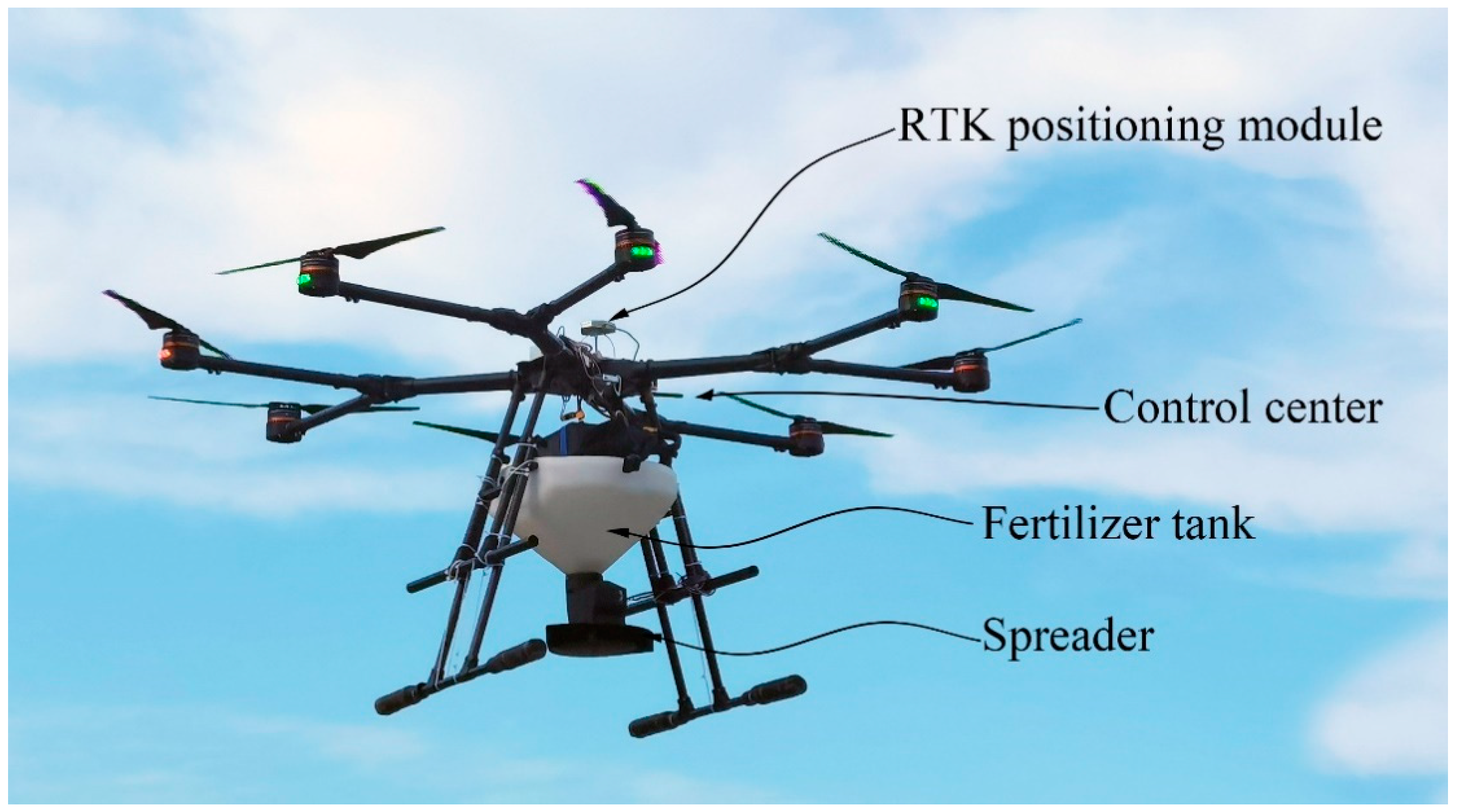
2.1.1. Control System Components

The control structure of the variable fertilizer application system consisted of three main units (Figure 2).
(1)
Central processing unit
The MCU chip was the core processor of the airborne spreading system, which significantly shortened the response time of the variable fertilizer application system and improved the stability of the system. The wireless communication module was integrated into the ground side and the airborne side for wireless data transmission between the ground base station and the spreading volume control unit. The wireless communication module used spread spectrum technology to ensure the reliability and stability of the system data transmission. The corresponding PWM signal was output by the MCU to drive the spreading unit for the variable fertilization operation after decoding the prescription map generated by the simulation imported by the host computer.
(2)
Ground base station unit
The communication of the ground base station was by the wireless transmission module, and the airborne spreading system after the prescription map was imported by the host computer, which was used to remotely monitor the operating status of the system and visualize as well as store the flight parameters (speed and altitude).
(3)
Spreading volume control unit
The real-time fertilizer application data of the spreading mechanism were recorded, and the motor speed and current position of the current spreading device were viewed on the screen. The data were stored in the storage module, which was applied to analyze whether the target area completed the fertilizer application according to the prescription map information after testing.

2.1.2. Hardware Integration of the Variable Fertilizer Application System

The main acquisition and output data of the variable fertilizer application system included the acquisition of Beidou geographic information data and flight speed, the generation of the PWM duty cycle and its output, the feedback of the real-time spreading volume, the correction of the deviation of the five parts of the weighted coefficient learning correction PID, and the description of the working parameters of the main components, as shown in Table 1.
The speed sensor was selected to detect the actual rotational speed per minute with high sensitivity by magnetic field induction, and the signal was outputted by a comparator. The pulse frequency was outputted by the Hall element inside the module to calculate the rotational speed of the spreading disc in real time.
The spreading device was integrated, and it consisted of a DC motor, rudder, and spreading disc. The DC motor was a miniature DC gear motor, the rudder was a large torque metal standard rudder, and the spreading disc was a three-leaf fan-shaped disc with a single fan angle of 120°. The DC motor and rudder were used to control the spreading speed and degree of opening and closing of the hatch opening, respectively, which to control the amount of spreading (Figure 3).

2.2. Variable Fertilization Control System Algorithm Design

2.2.1. Working Principle of Variable Fertilization

The goal of the variable fertilizer application technology was to precisely and stably adjust the actual volume spread by the system according to the change in the set value. The STM32F103ZET6 output different PWM duty cycle signals to the drive amplifier module, which drove the DC motor. The actual speed of the spreading disc was collected by the speed sensor, and it was compared and calculated with the set target speed. The difference value was transmitted to the STM32F103ZET6, and the processor made a single neural network adaptive adjustment according to the speed deviation to calculate the KP, KI, and KD parameters of the PID controller to incrementally regulate the rotational speed, leading to the parameters converging to the target value. The current voltage of the spreading system in real time was detected by the voltage stabilization module to ensure that the DC motor worked in a safe and controllable voltage range for spreading. The sensor operation data were transmitted to the PC by a wireless transmission module to be stored in real time during the operation, which was used in the later analysis. The control process of the variable fertilizer application system is shown in Figure 4.

2.2.2. Design of the Improved Single-Neuron PID Controller

The current control quantity and the value of the last control quantity perform the difference by the incremental PID (INPID) controller achieved a more stable control effect with a shorter calculation time. The coefficients KP, KI, and KD were the proportional coefficient, integral coefficient, and differential coefficient of the PID controller in Equation (1), respectively. When electromagnetic interference occurred in the control circuit, it was difficult for the PID controller to complete the controlled quantity in time. At the same time, the neural network with an adaptive function was selected to combine with the INPID control algorithm to design the weighted coefficient learning correction single-neuron PID (SNPID) controller after considering the characteristics of variable fertilizer device nonlinearity and the mutual interference of the control loops. The neural network algorithm is written into a program that can be recognized and imported into the MCU, and the speed sensor as well as other modules can transmit the acquired data into the MCU. At this time, the MCU automatically runs the learning rules to calculate the data and obtain the results. The adjustment of the real-time variable was achieved by learning rules to adaptively adjust its weights.
Δ u ( k ) = K P [ e ( k ) e ( k 1 ) ] + K I e ( k ) + K D [ e ( k ) 2 e ( k 1 ) + e ( k 2 ) ]
u ( k ) = u ( k 1 ) + Δ u ( k )
where KP is the scale factor; KI is the integral factor; KD is the differential coefficient; k is the digital sampling sequence number (k = 0, 1, 2); u(k) is the kth sampling actual speed value, r/min; e(k) is the kth sampling speed deviation, r/min.

2.2.3. Weighted Coefficient Learning-Modified Single-Neuron PID Control Strategy

The improved SNPID controller was adaptive and had autonomous learning capability to adjust the value of each component weighting coefficient ω i online, which can adaptively adjust the control intensity of proportional, integral, and differential links of PID. Single-neuron theory is an effective way to solve this problem for variable fertilization with strong coupling and natural instability [42]. The block diagram of the adaptive SNPID control system based on the learning correction of weighting coefficients is shown in Figure 5.
The weighted coefficient learning-modified single-neuron control algorithm and the adaptive learning algorithm are as follows.
x 1 ( k ) = e ( k ) e ( k ) = y set y out x 2 ( k ) = e ( k ) e ( k 1 ) x 3 ( k ) = e ( k ) 2 e ( k 1 ) + e ( k 2 )
where e(k) is the deviation of the kth sampling speed; X i ( k ) is the amount of state required for learning (k = 1, 2, 3, …); and y out is the output speed value.
u ( k ) = u ( k 1 ) + δ i = 1 3 ω i ( k ) x i ( k )  
where u ( k ) is the control signal of the controlled object input at the kth moment; δ is the neuron gain coefficient; and δ > 0; ω i is the corresponding weighting factor at the moment x i ( k ) .
ω i = ω i ( k ) / δ i = 1 3 | ω i ( k ) |
In this paper, the supervised Hebb learning rule was applied in the weighted coefficient learning-modified SNPID controller, and the specific learning rule is shown in Equation (6).
ω 1 ( k + 1 ) = ω 1 ( k ) + θ i z ( k ) e ( k ) x 1 ( k ) ω 2 ( k + 1 ) = ω 2 ( k ) + θ p z ( k ) e ( k ) x 2 ( k ) ω 3 ( k + 1 ) = ω 3 ( k ) + θ d z ( k ) e ( k ) x 3 ( k )
where θ i is the integral learning rate; θ p is the proportional learning rate; and θ d is the differential learning rate.
Comparing Equations (1) and (2) with Equation (6) shows that the formation of the expression was the same. However, the three coefficients were unchanged after the rectification was completed in Equations (1) and (2). The self-tuning function was accomplished by the learning rules in Equation (6) ω i (i = 1, 2, 3). Therefore, the SNPID controller was a PID controller with variable coefficients.
Considering that the online learning of the PID parameters in the control process were mainly related to e ( k )   and   Δ e ( k ) , the weighting coefficients were optimized by replacing x i ( k ) with e ( k ) + Δ e ( k ) .
ω 1 ( k + 1 ) = ω 1 ( k ) + θ i z ( k ) e ( k ) [ e ( k ) + Δ e ( k ) ] ω 2 ( k + 1 ) = ω 2 ( k ) + θ p z ( k ) e ( k ) [ e ( k ) + Δ e ( k ) ] ω 3 ( k + 1 ) = ω 3 ( k ) + θ d z ( k ) e ( k ) [ e ( k ) + Δ e ( k ) ]
in the formula: Δ e ( k ) = e(k) − e(k − 1); z(k) = e(k); ω i is the weight factor.
The weight coefficients of the single-neuron network in Equation (7) were adjusted by the weighting coefficient learning correction, and x i ( k ) was replaced by e(k) + ∆e(k). The method effectively improved the control strength of the weighting coefficients of each component, eliminated stability errors, and improved the dynamic characteristics of the system. In addition, the anti-interference performance of the system was improved. The speed deviation signal e(k) collected by the variable fertilizer application system in the figure was converted as the input signal of the neural network, and the deviation between the actual spreading speed and the set value was used as the input of the SNPID controller by solving the deviation. Then, the parameters were adjusted through self-learning to make the current spreading speed close to the target speed. The detailed flow of the control algorithm is shown in Figure 6.

2.3. Indoor Experimental Design

To verify the effectiveness and reliability requirements of the variable fertilizer application control system in the SNPID control algorithm, the SNPID control algorithm was constructed using MATLAB software (Math Works, Natick, MA, USA). The step-response simulation analysis was performed and compared with the original INPID control algorithm.

2.3.1. Comparison Simulation of the Control Algorithm and Dynamic Change following the Test of Spreading Volume

The trial-and-error method was used to determine the proportional coefficient KP = 10.5, differential coefficient KI = 0.12, and integral coefficient KD = 4.5 of the INPID. The SNPID was adjusted by weighted coefficients to improve the learning rule. After nearly 30 debugging cycles, the neuron proportional coefficient δ was 0.12, and the learning rates of proportional–integral–differential θi, θp, and θd were taken as 0.5, 0.3, and 0.8, respectively.
To effectively verify the motor speed control in the system of the algorithm, a comparison test of dynamic following of spreading volume was conducted indoors. Considering the spreading width and the wide range of spreading volumes based on the prescription map to test, three kinds of rotational speeds were measured (100, 300, and 600 r/min) and set for 10 s. The two control algorithms were read into STM32F103ZET6: INPID, and the KP, KI, and KD values were 0.07, 0.003, and 0.20, respectively. The parameter δ was 0.5, the initial value of the neuron weights was 0.1, and the learning rates of integral differentiation θi, θp, and θd were 0.73, 0.008, and 0.27, respectively.

2.3.2. Testing the Effect of Different Speed Gradients and Baffle Gradients on the Dispersion Volume

To analyze the effects of the INPID control method and SNPID control method on the spreading volume in the variable process, it was feasible to test the spreading volume indoors using a bench test. When the speed of the spreading disc was faster, particle jumping was weaker, and the effect was less. Five gradients were selected for the bench test to simulate the spreading comparison test and compare the average value of the discharge volume at each speed. Two different shapes and sizes of urea (UR) and compound fertilizer (CF) were selected for the test, and the physical characteristics of the two fertilizers were calibrated. The resting angle was measured using the funnel method, and the sliding friction angle was measured using the plate tilt method. The measurement results are shown in Table 2.
A 3D printer (iBrider i341, Shanghai Xing xiu Intelligent Technology Co., Ltd., Shanghai, China) was used to make a prototype of the spreading device and conduct an indoor bench test (Figure 7). A certain amount of the material under test (compound fertilizer/urea) was first filled into the fertilizer tank, and the speed value of the spreading disc was set. The motor driver was controlled to rotate continuously for 20 s at the set speed, and the weight of the discharged granular material was recorded and converted into the discharge volume per minute (kg/min). To reduce the disturbance of pulsation and obtain an accurate discharge range as well as test results, the minimum speed was set at 200 r/min. Five levels (200, 400, 600, 800, 1000 r/min) and five baffle openings (2–10%) were set. The preliminary test was performed, and the baffle opening was set at 10%. When the baffle opening was set to more than 10%, a large amount of material was discharged, which caused serious errors and was not conducive to the test. The above parameters were repeated twice for each treatment to achieve accurate measurement and error reduction. The indoor test design is shown in Table 3. The instrument items used for the test included a DC motor controller, PWM speed regulator, electronic balance (weighing range 30 kg, accuracy 0.01 g, Shenzhen Anheng Weighing Electronic Co., Ltd., Shenzhen, China), nylon yarn mesh belt, plastic bucket, timer, and granular fertilizer.

2.4. Outdoor Performance Test Design

The outdoor performance test of the variable fertilizer application system was conducted combined with the indoor research results, which were used to test the operation status of the fertilizer-spreading distribution and evaluate the uniformity of the accuracy of the fertilizer application volume of the agricultural UAV variable fertilizer application system. The test data and the setting of the spreading volume were transmitted to the upper computer through the wireless communication module.

2.4.1. Test Conditions

The test was conducted in April 2022 at the experimental station of Shenyang Agricultural University, Shenhe District, Shenyang, Liaoning Province (41°49′22″ N, 123°34′0″ E). The test site area was 300 m2 with clear weather, temperatures from 12 °C to 18 °C, average humidity of 5%, ambient wind direction (southeast), and wind speeds less than 2.0 m/s. The test fertilizers were compound granular fertilizers and urea used in the north (moisture content was 1.03%, and the particle diameter was 4.02 mm, Shenyang Massive Agrochemical Co., Ltd., Shenyang, China). The test method and indices were referred to GB/T 5262-2008 [43], and the test method of the centrifugal spreader specified followed ISO 5690 [44].

2.4.2. Test Method

The plastic tarp (China Shenzhen Chuangda Canvas Products Co., Shenzhen, China) was placed in the testing area during the variable fertilizer spreading for fertilizer recycling. The relevant viscous media was placed on the inner wall of the pellet collection box (Handan Ruheng Plastic Industry Co., Ltd., Handan, China) to reduce test errors caused by fertilizer jumping with the high-speed centrifugal force. The pellet collection box of 70 was arranged in a 10 × 7 matrix (30 cm × 15 cm × 10 cm) with a column interval of 1 m and row interval of 0.5 m. The variable fertilizer-spreading system entered the test area (identified by the plastic tarp) after starting in the operational stability zone. The system started spreading at a certain operating speed from the laterally symmetrical center, and for each group of tests, the fertilizer tank was adjusted to be greater than 70% of the total capacity, and the whole machine was calibrated in the corresponding operating state. After a single treatment, the mass of fertilizer particles in each collection bucket was weighed using an electronic balance to characterize the distribution of fertilizer particles and ensure the accuracy of the data for the measured area. A schematic diagram of the test protocol and performance tests is shown in Figure 8.
According to the design scheme, the range of flight height (h) was set from 1.5 m, 2 m, 3 m, the range of spreading disc speed (n) was from 400 to 800 r/min, and the range of baffle opening was from 4% to 8%. A three-factor, three-level orthogonal test was designed according to the baffle expansion, spreading disc speed, and flight height, and combined with the orthogonal test design principle (L9 (34)) [45]. (1–6 m is the height range of agricultural drones.) In order to ensure the effect of the fertilization and reduce the error of the fertilization, three gradients of 1.5 m, 2 m, and 3 m were selected for the outdoor test. To avoid errors, three sets of replicate trials were conducted with nine gradient treatments, and the number of flights was 27. The single gradient was set to 70 points. The particle data (bagged and labeled for preservation) were collected from each sampling site after the experiment and brought back to the laboratory for further analysis; the factor levels are shown in Table 4.

2.4.3. Evaluation Indices

According to the performance requirements of the fertilizer spreader in accordance with the GB/T 5262-2008 standard [43], the evaluation index was chosen to be the “accuracy of discharge volume”. The coefficient of variation of fertilizer particle distribution and the error λ of the spreading volume per unit area were calculated separately to evaluate the performance of the variable fertilizer spreader, and the average value was obtained by repeating the test three times. The accuracy of the discharge volume was expressed by the coefficient of variation of the actual discharge volumes at different rotational speeds of the centrifugal discs. The smaller the coefficient of variation, the smaller the error of the measured rotational speed in the discharge volume under the treatment, and the better the accuracy of the discharge volume. The test index was calculated as follows:
CV = n P × 100 %
Ρ = 1 x P n
n = 1 x 1 ( P n P ) 2
where P is the average value of the mass of granular material per unit time in a single treatment, kg; P n is the mass of particulate material measured for the nth time, kg; x indicates the number of repeated tests for each treatment, (x = 1, 2, 3…); and n denotes the standard deviation of the total mass of granular fertilizer measured in each treatment, kg.
λ = | K A G | G × 100 %
where λ is the error in the amount of fertilizer spread per unit area, %; K is the total mass of fertilizer particles in the test area, g; A is the area of the test area, m2; and G is the theoretical target fertilizer application rate, g/m2.

2.5. Data Processing

After the outdoor tests were completed, the arranged particle collection boxes were numbered and brought back to the laboratory for processing, and the weight was measured and recorded by an electronic balance. The collected weight data were analyzed and processed by Microsoft Excel 2019 software (Microsoft Corporation, Seattle, WA, USA), and used to calculate the mean of the two evaluation indicators to calibrate the best solution for the three-factor, three-level orthogonal test. After obtaining the data for Cv and λ, the best solution was further refined by designing an ANOVA. The data for the sum of squares, degrees of freedom, mean square sum, F test, and significance in ANOVA were jointly analyzed by SPSS 26.0 software (IBM Corporation, Armonk, NY, USA) and Origin 2018 software (Origin Lab, Inc., Northampton, MA, USA).

3. Results and Discussion

3.1. Indoor Evaluation of Simulation Effect of Control Algorithm and Comparison of Dynamic Characteristics

The simulation results are shown in Figure 9. The response speed and overshoot of the INPID were larger than those of the SNPID, and some overshoot was present in the INPID. Table 5 shows that the rise time of the system was 0.131 s with no overshoot and steady-state error for a given step signal under the control of the SNPID. The rise time of the system was 0.585 s with 0.15% overshoot under the control of the INPID. In summary, the delay time of the SNPID under the step response was short, which was suitable for the fast adjustment of the spreading flow rate under the high-speed moving conditions of the agricultural UAV with a good control effect. This verified that the response sensitivity of the system was improved compared with the INPID after adjusting the weighted coefficient of the SNPID by learning correction. Zhang et al. [46] designed a detection system of variable fertilizer application tractor lag time based on slotted wheels and reduced the lag distance using a lag distance compensation method based on planar coordinates. The time lag of the fertilizer application system was the main reason for excessive fertilizer application in ground machinery. Chen et al. [47] improved the time lag of the sensor-based variable fertilizer application system by adding a feedforward correction of 2.04 s to the control program. Compared with previous studies, the simulation results showed that the system quickly adjusted the current state of the controlled hardware within a short time using the SNPID algorithm, which substantially improved the stability of the system and effectively reduced the impact of the reduced time lag phenomenon on the spreading effect. Notably, the above test data were the result of the system simulation test without accessing the hardware (DC motor).
The simulated data of the dynamic characteristics comparison test are shown in Figure 10. The reason for choosing three gradients was that the lowest speed of the selected DC motor was 100 r/min. The second and third gradients were set to 300 r/min and 500 r/min, respectively, to investigate the variability of the continuously varying test data. The INPIN and SNPID were used to adjust the rotational speed, and the spreading disc speed was fed back by the speed sensor in real time. The reason for choosing 10 s in a single gradient (300 r/min) at 10–15 s to start the discussion was because the DC motor in the start and stop period had 1–2 s for a rapid step or 1–2 s for stopping quickly after the power failure. The response speed and rise speed had a certain error, which affected the measured data. Thus, the middle region was chosen as the main object of analysis to effectively avoid this situation. The overshoot of the INPID from a 100 r/min step to a 300 r/min gradient was larger than that of the SNPID algorithm. The motor jittered when the signal was transmitted to the DC motor. The average time delay of the jitter was 1 s through multiple steps. In contrast, the SNPID overshot by 0.23 s during the step-control process and then converged quickly. The DC motor had no significant jitter. In addition, the peak-to-valley difference of the INPID was large after contacting the ideal target 18 times, and all of them were overshot. However, the peak-to-valley difference of the SNPID was small with no overshoot, and the control effect following the ideal target was smooth.
The test data are shown in Table 6, and the following conclusions were drawn from three successive variable fertilization adjustments. A lag of 1–1.2 s resulted when using the INPID control algorithm, and the average rise time was 1.3 s. The maximum overshoot and absolute value of the average error at the third variable (500 r/min) were 9.85% and 11.43%, respectively, and the control effect was unstable. The fluctuation of the spreading volume compared with the set value was small for the SNPID control algorithm, which solved the problem of excessive overshoot caused by the INPID. The maximum overshoot was 3.85% in a single adjustment, which was less than that of the INPID control method. The algorithm regulation process had a time lag of 0.7–0.9 s, which was because the processor transmitted the relevant instructions after high-speed computing when the DC motor was controlled by the STM32F103ZET6 processor module in the SNPID algorithm. The response speed was better than that of the INPID, and the average rise time was 0.88 s. The maximum average absolute error during the adjustment process was 7.30%, and the control effect was stable. Both tests were conducted with wireless transmissions.
According to the indoor dynamic comparison, it was concluded that when the target speed was set to 100 r/min, the spreading disc had a strong pulsation disturbance. The longitudinal jitter was because when the speed was low, the pulse signal was weak for the SNPID control algorithm, and the rotation of the spreading disc could not be stably controlled. In addition, the lack of rotational speed led to the accumulation of fertilizer on the spreading disc at the discharge port. Thus, 100 r/min of the gradient was not considered in the following test.

3.2. Analysis of Indoor Test Results of Variable-Rate Control System

The purpose of the discharge test was to study the range of the discharge volume and the accuracy of the fertilizer discharge at each speed. The spreading disc and baffle plate at the discharge port had a strong restraint on the particle discharge, which significantly limited the slipping of the free particles. The discharge volume was adjusted by controlling the speed of the spreading mechanism. Figure 11 shows the test data from the indoor test program in Table 3. The measured fertilizer discharge volume increased with increasing speed. Furthermore, the baffle opening factor had a great impact on the discharge volume at the same speed. Two measured materials (compound fertilizer and urea) had large errors (the spreading volume exceeded the predicted value) at 200 r/min, and the baffle plate was greater than or equal to 4%. The material falling proportion increased with the increase in the baffle plate opening, and the slow speed (200 r/min) of the disc caused the granular fertilizer to not separate from the contact surface of the spreading disc in time, which resulted in the error. Additionally, the coefficient of variation (CV) of the particle distribution was 6.89%, which was the highest CV among all of the treatments and confirmed that the baffle opening was the primary factor affecting the spreading effect. The factor had increasing attention in the subsequent outdoor tests. In addition, the maximum discharge of all baffles varied widely in the tested speed range. The minimum discharge variation excluded the error when the baffle was 200 r/min, and the rest were small. The maximum displacement of each speed corresponding to the baffle discharging compound fertilizer was from 7.458 kg/min (2% baffle) to 13.833 kg/min (10% baffle), and the maximum displacement range of the discharge urea was from 7.856 kg/min (2% baffle) to 12.733 kg/min (10% baffle). All of the measured data met the requirements for variable fertilizer application by UAV. Combined with the above data, the 200 r/min treatment and the 2% baffle parameter were discarded to obtain accurate test data in the outdoor orthogonal test.

3.3. Performance Analysis of Outdoor Application of Variable-Rate Control System

To accurately evaluate the performance of the fertilizer dispersal after the optimization of the spreading device parameters, the influence of disc rotation speed and baffle opening on granular fertilizer spreading was considered. The main operating parameters that affected the variable fertilizer application included baffle retraction, spreading disc rotation speed, and drone height. The fertilizer particles in the test area were collected at fixed points, and the coefficient of variation of the particle distribution within the effective width of fertilizer spreading was used as the evaluation index. The Cv of the particle distribution within the effective spreading width was used as evaluation index a, which characterized the uniformity of the spreading distribution of the system. The error of the fertilizer application per unit area was used as evaluation index b, which characterized the accuracy of the fertilizer application per unit area.
The orthogonal test protocols and results of the outdoor test system performance are shown in Table 7; A, B, and C are the values of q, n, and h, respectively. Some differences were present in the significance of the effect of the three factors for different evaluation indicators from the extreme difference analysis (R value) in Table 7. When the evaluation index was prioritized with the coefficient of variation of spreading particle distribution, the order of influence was A, B, and C. The best combination was A2B2C1. In addition, the Cv increased with the increase in factor A, decreased with the increase in factor B, and decreased and then increased with the increase in factor C. When the evaluation index was prioritized by the spreading volume error λ, the order of influence of λ was B, A, and C, and the better combination was A1B2C2. The spreading error λ tended to decrease and then increase with the increasing factors of A, B, and C.
The results of the ANOVA are shown in Table 8. The ANOVA of the Cv showed that FA > FB > FC, which indicated that factor A had the most significant effect, factor B had the second most significant effect, while factor C had the least significant effect (p < 0.05) on the Cv. The ANOVA of λ showed that FB > FA > FC, which indicated that factor B had the most significant effect, factor A had the second most significant effect, and factor C had the least significant effect (p < 0.05) on the fertilizer-spreading error λ, which was consistent with the results of the ANOVA. The ANOVA results showed that the optimal combination of factor levels was selected according to the evaluation indices, and the optimal combination A2B2C1 was selected when the Cv was preferred, and the Cv was 9.80% and λ was 7.65%. The optimal combination A1B2C2 was selected when λ was preferred; the Cv was 11.98%, and λ was 7.02%. Comparing the best combinations with different evaluation indices and referring to the requirements of the relevant standards for the operation of fertilizer-spreading machinery (Cv ≤ 15% and λ ≤ 10%), the better factor level combination was A1B2C2. The performance of the whole fertilizer-spreading system was best when the baffle retraction q was 4%, the disc speed n was 600 r/min, and the unmanned height h was 2 m.
The actual spreading speed and the target spreading speed were detected by the speed sensor during the outdoor test, as shown in Table 9. The system performed variable fertilization according to the target speed during the actual outdoor operation. The average absolute error between the actual spreading volume and the target spreading volume in the outdoor test was 3.51%, and the average rise time of the spreading system during the four outdoor variable operations was 0.81 s. The DC motor speed was effectively and quickly adjusted, and the response time was within 1 s. The overshoot was always maintained at a low level with increasing spreading speed, and the actual spreading speed was controlled to follow the target speed and achieve accurate variables.
Variable-rate control systems are used in ground machines. Zha et al. [48] designed a block-wheel screw fertilizer spreader and designed orthogonal simulation tests to evaluate its performance. The results showed that the minimum coefficient of variation of fertilizer uniformity was 19.27%. Jin et al. [49] designed a variable-rate control system for a ground variable spreader. The results of field trials with preset doses showed that the accuracy of fertilizer application was 94%. Reyes et al. [24] investigated the performance of a variable-speed fertilizer control system in a no-till drill based on prescription charts, which was equipped with a fertilizer application unit driven by a remote hydraulic system of the tractor. Constant and variable speed fertilizer application volumes in the field were measured. Compared with preset volumes, the overall error range of the fertilizer volume was from 12% to 14%. Compared with previous studies, the UAV variable spreading control system showed high accuracy, with a coefficient of variation of 9.80% and good performance in variable fertilizer application. In addition, UAV-based variable fertilizer application technology prevented contact with plants, which reduced the collapse of crops and can play an important role in improving yields.

4. Conclusions

An SNPID-based variable fertilizer application control system was developed to meet the requirements of the current rice variable fertilizer application operation. An STM32F103ZET6 was the core controller used to integrate the sensor data and coordination feedback information, and it was combined with the prescription map strategy model to respond to the target fertilizer demand. The fertilizer application amount in real time was adjusted by a DC motor, and the response characteristics and fertilization accuracy were evaluated by indoor and outdoor fertilizer discharge tests. At the same time, different types of DC motors will be compared and tested to ensure the accuracy of the test data in future research. Moreover, the use of higher-precision sensors and positioning systems will be used to reflect the real-time growth of crops to accurately predict the crop growth trend. Hence, the accuracy of the fertilization prescription map could be effectively improved, which would further complete the accuracy of the variable fertilization work [50].
The main conclusions of this paper are as follows.
(1)
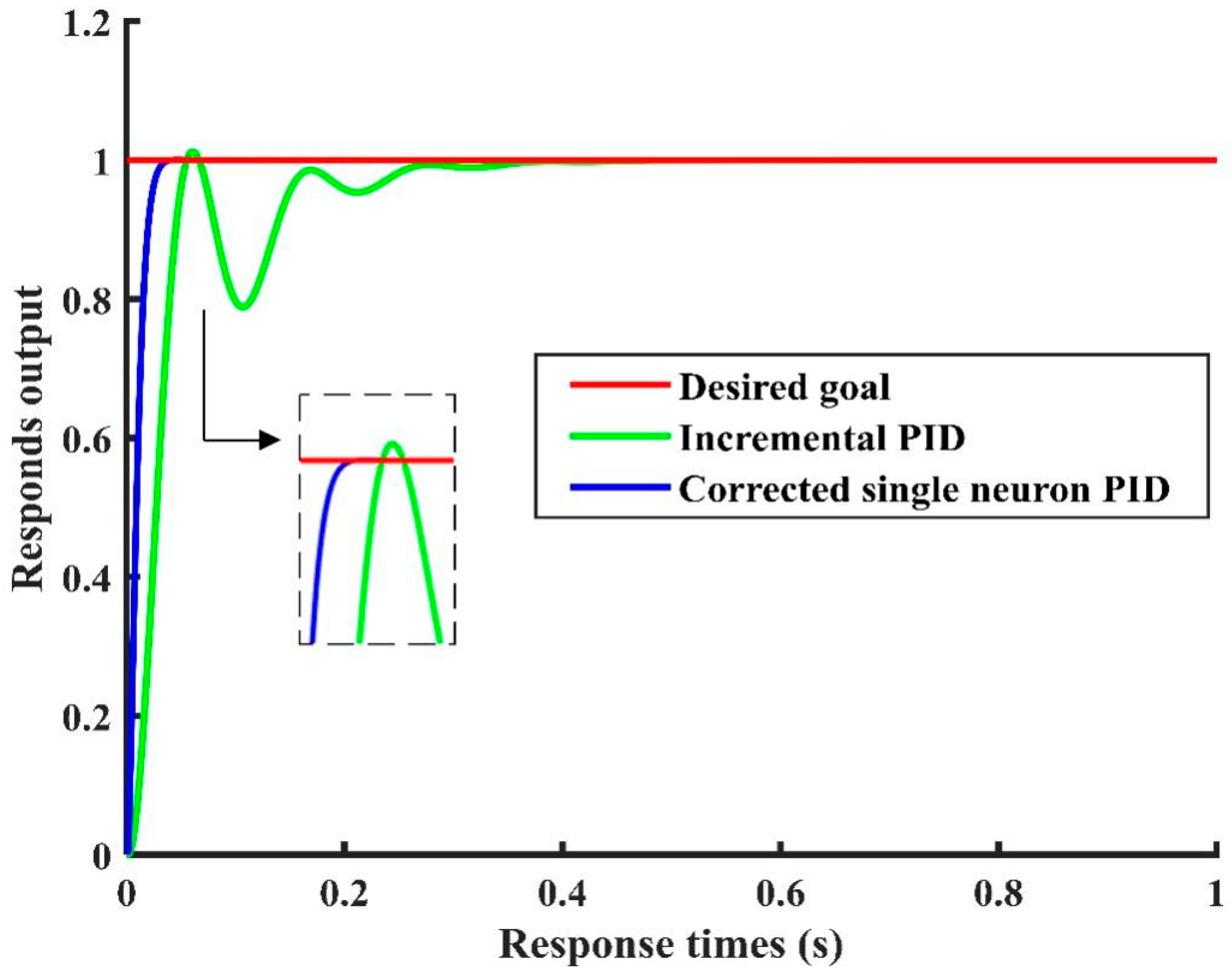
The simulations and comparison tests of the INPID and SNPID control methods were conducted by MATLAB engineering software. The results of the single-variable tests showed that the response speed of the DC motor was the fastest and showed little increase with time when using the SNPID control method; this was better than the performance of the INPID control method.
(2)
The results of the indoor continuous variable process experiment showed that the SNPID adaptive control algorithm underwent little change during a short time compared with the fluctuation amplitude of the set value. The average rise time of the system was 0.88 s, and the system had good dynamic stability and tracking performance.
(3)
The outdoor spreading performance test results showed that the three parameters of the fertilizer-spreader operation were significantly different, with different evaluation indices. When the coefficient of the variation of particle distribution Cv was the evaluation index of the target operation width (15 m), the main and secondary factors were A (baffle opening), B (spreading disc speed), and C (flight height), and the best combination of factor levels was A2B2C1. When the relative error of fertilizer application λ was the evaluation index, the main and secondary factors were B (spreading disc speed), A (baffle opening), and C (flight height), and the best combination of factor levels was A1B2C1. The overall best combination of factor levels was A1B2C2, and the value of q was 4%, n was 600 r/min, h was 2 m, the Cv was 11.98%, and λ was 7.02%. The spreading system showed the best performance of spreading fertilizer, and the spreading volume control error was 7.30%. The monitoring error of the speed measurement module was less than 30 r/min, which effectively accomplished accurate variable fertilizer application. This demonstrated that the designed centrifugal variable fertilizer application system improved the uniformity and accuracy of the fertilizer application, which provided technical support for traditional fertilizer application.
Overall, this study confirmed that the control system was fully functional and effectively controlled the amount of granular fertilizer applied, which can bring greater benefits than traditional methods to farmers and agricultural production. However, the spreading error mainly depended on the dynamic response of the UAV mechanical metering system and the calibration resolution error of the control system. Additional research is needed on the rate of fertilizer application variation, steady-state application error, and optimization of the metering device to improve the performance of the system.

Author Contributions

D.S., W.Y. and C.C. designed the research. Y.L., Z.Z. and Y.W. participated in the measurements and data analysis. D.S. wrote the first draft of the manuscript. W.Y., F.Y. and T.X. revised and edited the final version of the manuscript. F.Y. and C.C. are responsible for funding acquisition. All authors have read and agreed to the published version of the manuscript.

Funding

This research was funded by the Natural Science Foundation of Liaoning (LSNZD202005).

Institutional Review Board Statement

Not applicable.

Informed Consent Statement

Not applicable.

Data Availability Statement

Not applicable.

Acknowledgments

The authors acknowledge Daoming Sun and Dengyue Zheng from Shenyang Agricultural University for supporting this work.

Conflicts of Interest

The authors declare no conflict of interest. The funders had no role in the design of the study; in the collection, analyses, or interpretation of data; in the writing of the manuscript; or in the decision to publish the results.

References

  1. Balafoutis, A.; Beck, B.; Fountas, S.; Vangeyte, J.; Wal, T.; Soto, I.; Gómez-Barbero, M.; Barnes, A.; Eory, V. Precision Agriculture Technologies Positively Contributing to GHG Emissions Mitigation, Farm Productivity and Economics. Sustainability 2017, 9, 1339. [Google Scholar] [CrossRef] [Green Version]
  2. Yinyan, S.; Zhichao, H.; Xiaochan, W.; Odhiambo, M.O.; Weimin, D. Motion analysis and system response of fertilizer feed apparatus for paddy Variable-Rate fertilizer spreader. Comput. Electron. Agric. 2018, 153, 239–247. [Google Scholar] [CrossRef]
  3. Ding, S.; Bai, L.; Yao, Y.; Yue, B.; Fu, Z.; Zheng, Z.; Huang, Y. Discrete element modelling (DEM) of fertilizer dual-banding with adjustable rates. Comput. Electron. Agric. 2018, 152, 32–39. [Google Scholar] [CrossRef]
  4. Chen, C.; He, P.; Zhang, J.; Li, X.; Ren, Z.; Zhao, J.; He, J.; Wang, Y.; Liu, H.; Kang, J. A fixed-amount and variable-rate fertilizer applicator based on pulse width modulation. Comput. Electron. Agric. 2018, 148, 330–336. [Google Scholar] [CrossRef]
  5. Zeng, S.; Tan, Y.; Wang, Y.; Luo, X.; Yao, L.; Huang, D.; Mo, Z. Structural design and parameter determination for fluted-roller fertilizer applicator. Int. J. Agric. Biol. Eng. 2020, 13, 101–110. [Google Scholar] [CrossRef]
  6. Yu, H.; Ding, Y.; Liu, Z.; Fu, X.; Dou, X.; Yang, C. Development and Evaluation of a Calibrating System for the Application Rate Control of a Seed-Fertilizer Drill Machine with Fluted Rollers. Appl. Sci. 2019, 9, 5434. [Google Scholar] [CrossRef] [Green Version]
  7. Niu, K.; Bai, S.; Zhou, L.; Zhao, B.; Liu, L.; Yuan, Y.; Yang, D.; Xiong, S.; Zhang, W. Design and Experimental Research of Variable Formula Fertilization Control System Based on Prescription Diagram. Appl. Sci. 2021, 12, 325. [Google Scholar] [CrossRef]
  8. Sugirbay, A.M.; Zhao, J.; Nukeshev, S.O.; Chen, J. Determination of pin-roller parameters and evaluation of the uniformity of granular fertilizer application metering devices in precision farming. Comput. Electron. Agric. 2020, 179, 105835. [Google Scholar] [CrossRef]
  9. Haitao, L.; Yongqian, D.; Hongfeng, Y.; Minfeng, J.; Yizhuo, J.; Xiuqing, F. Signal processing method and performance tests on weighting-sensor-based measuring system of output quantity for a seeding and fertilizing applicator. IFAC-PapersOnLine 2018, 51, 536–540. [Google Scholar] [CrossRef]
  10. Bhakta, I.; Phadikar, S.; Majumder, K. State-of-the-art technologies in precision agriculture: A systematic review. J. Sci. Food Agric. 2019, 99, 4878–4888. [Google Scholar] [CrossRef]
  11. Finger, R.; Swinton, S.M.; El Benni, N.; Walter, A. Precision Farming at the Nexus of Agricultural Production and the Environment. Annu. Rev. Resour. Econ 2019, 11, 313–335. [Google Scholar] [CrossRef] [Green Version]
  12. Guo, S.; Li, J.; Yao, W.; Zhan, Y.; Li, Y.; Shi, Y. Distribution characteristics on droplet deposition of wind field vortex formed by multi-rotor UAV. PLoS ONE 2019, 14, e0220024. [Google Scholar] [CrossRef] [PubMed] [Green Version]
  13. Sreekantha, D.D.K. Applications of Unmanned Ariel Vehicles (UAV) in Agriculture: A Study. Int. J. Res. Appl. Sci. Eng. 2018, 6, 1162–1166. [Google Scholar] [CrossRef]
  14. Hassler, S.C.; Baysal-Gurel, F. Unmanned Aircraft System (UAS) Technology and Applications in Agriculture. Agronomy 2019, 9, 618. [Google Scholar] [CrossRef] [Green Version]
  15. Latif, M.A. An Agricultural Perspective on Flying Sensors: State of the Art, Challenges, and Future Directions. IEEE Geosci. Remote Sens. Mag. 2018, 6, 10–22. [Google Scholar] [CrossRef]
  16. Šarauskis, E.; Kazlauskas, M.; Naujokienė, V.; Bručienė, I.; Steponavičius, D.; Romaneckas, K.; Jasinskas, A. Variable Rate Seeding in Precision Agriculture: Recent Advances and Future Perspectives. Agriculture 2022, 12, 305. [Google Scholar] [CrossRef]
  17. Song, C.; Zang, Y.; Zhou, Z.; Luo, X.; Zhao, L.; Ming, R.; Zi, L.; Zang, Y. Test and Comprehensive Evaluation for the Performance of UAV-Based Fertilizer Spreaders. IEEE Access 2020, 8, 202153–202163. [Google Scholar] [CrossRef]
  18. Lan, Y.; Thomson, S.J.; Huang, Y.; Hoffmann, W.C.; Zhang, H. Current status and future directions of precision aerial application for site-specific crop management in the USA. Comput. Electron. Agric. 2010, 74, 34–38. [Google Scholar] [CrossRef] [Green Version]
  19. Sui, R. Performance Assessment of a Variable-Rate Fertilizer Applicator. J. Agric. Sci. 2019, 11, 25–30. [Google Scholar] [CrossRef]
  20. Song, C.; Zhou, Z.; Zang, Y.; Zhao, L.; Yang, W.; Luo, X.; Jiang, R.; Ming, R.; Zang, Y.; Zi, L.; et al. Variable-rate control system for UAV-based granular fertilizer spreader. Comput. Electron. Agric. 2021, 180, 105832. [Google Scholar] [CrossRef]
  21. Zhang, C.; Kovacs, J.M. The application of small unmanned aerial systems for precision agriculture: A review. Precis. Agric. 2012, 13, 693–712. [Google Scholar] [CrossRef]
  22. Balafoutis, A.T.; Evert, F.K.V.; Fountas, S. Smart Farming Technology Trends: Economic and Environmental Effects, Labor Impact, and Adoption Readiness. Agronomy 2020, 10, 743. [Google Scholar] [CrossRef]
  23. Hunt, E.R.; Daughtry, C.S.T. What good are unmanned aircraft systems for agricultural remote sensing and precision agriculture? Int. J. Remote Sens. 2017, 39, 5345–5376. [Google Scholar] [CrossRef] [Green Version]
  24. Reyes, J.F.; Esquivel, W.; Cifuentes, D.; Ortega, R. Field testing of an automatic control system for variable rate fertilizer application. Comput. Electron. Agric. 2015, 113, 260–265. [Google Scholar] [CrossRef]
  25. Guan, S.; Fukami, K.; Matsunaka, H.; Okami, M.; Tanaka, R.; Nakano, H.; Sakai, T.; Nakano, K.; Ohdan, H.; Takahashi, K. Assessing Correlation of High-Resolution NDVI with Fertilizer Application Level and Yield of Rice and Wheat Crops using Small UAVs. Remote Sens. 2019, 11, 112. [Google Scholar] [CrossRef] [Green Version]
  26. Feng, S.; Cao, Y.; Xu, T.; Yu, F.; Zhao, D.; Zhang, G. Rice Leaf Blast Classification Method Based on Fused Features and One-Dimensional Deep Convolutional Neural Network. Remote Sens. 2021, 13, 3207. [Google Scholar] [CrossRef]
  27. Zhao, D.; Feng, S.; Cao, Y.; Yu, F.; Guan, Q.; Li, J.; Zhang, G.; Xu, T. Study on the Classification Method of Rice Leaf Blast Levels Based on Fusion Features and Adaptive-Weight Immune Particle Swarm Optimization Extreme Learning Machine Algorithm. Front. Plant Sci. 2022, 13, 879668. [Google Scholar] [CrossRef]
  28. Wu, Z.; Li, M.; Lei, X.; Wu, Z.; Jiang, C.; Zhou, L.; Ma, R.; Chen, Y. Simulation and parameter optimisation of a centrifugal rice seeding spreader for a UAV. Biosyst. Eng. 2020, 192, 275–293. [Google Scholar] [CrossRef]
  29. Alameen, A.A.; Al-Gaadi, K.A.; Tola, E. Development and performance evaluation of a control system for variable rate granular fertilizer application. Comput. Electron. Agric. 2019, 160, 31–39. [Google Scholar] [CrossRef]
  30. Han, C.-W.; Lee, S.-Y.; Hong, Y.-K.; Kweon, G.-Y. Development of a variable rate applicator for uniform fertilizer spreading. Int. J. Agric. Biol. Eng. 2019, 12, 82–89. [Google Scholar] [CrossRef]
  31. Chattha, H.S.; Zaman, Q.U.; Chang, Y.K.; Read, S.; Schumann, A.W.; Brewster, G.R.; Farooque, A.A. Variable rate spreader for real-time spot-application of granular fertilizer in wild blueberry. Comput. Electron. Agric. 2014, 100, 70–78. [Google Scholar] [CrossRef]
  32. Azis, A.; Setiawan, R.P.A.; Hermawan, W.; Mandang, T. Dynamic performance test of auger-type metering device for Variable Rate Fertilizer Applicator (VRFA). IOP Conf. Ser. Earth Environ. Sci. 2020, 486, 012064. [Google Scholar] [CrossRef]
  33. Saleem, S.; Zaman, Q.; Schumann, A.; Madani, A.; Chang, Y.; Farooque, A. Impact of variable rate fertilization on nutrients losses in surface runoff for wild blueberry fields. Appl. Eng. Agric. 2014, 30, 179–185. [Google Scholar]
  34. Tang, X.Y.; Chen, Y.Z.; Peng, Y.K.; Wang, X.; Xu, Y.; Yang, W.L.; Wang, W. A DSP-Based Control System for Precision Variable Rate Fertilization. Adv. Mater. Res. 2013, 605, 1408–1414. [Google Scholar] [CrossRef]
  35. Yuan, J.; Liu, C.-L.; Li, Y.-M.; Zeng, Q.; Zha, X.F. Gaussian processes based bivariate control parameters optimization of variable-rate granular fertilizer applicator. Comput. Electron. Agric. 2010, 70, 33–41. [Google Scholar] [CrossRef]
  36. Zhang, J.; Liu, G.; Luo, C.; Hu, H.; Huang, J. MOEA/D-DE based bivariate control sequence optimization of a variable-rate fertilizer applicator. Comput. Electron. Agric. 2019, 167, 105063. [Google Scholar] [CrossRef]
  37. Ishola, T.A.; Yahya, A.; Shariff, A.R.M.; Aziz, S.A. A Novel Variable Rate Pneumatic Fertilizer Applicator. Instrum. Sci. Technol. 2014, 42, 369–384. [Google Scholar] [CrossRef]
  38. Grafton, M.C.E.; Irwin, M.E.; Sandoval-Cruz, E.A. Measuring the response of variable bulk solid fertiliser application by computer-controlled delivery from aircraft. N. Z. J. Agric. Res. 2021, 1–13. [Google Scholar] [CrossRef]
  39. Li, J.Y.; Lan, Y.B.; Zhou, Z.Y.; Zeng, S.; Huang, C.; Yao, W.; Zhang, Y.; Zhu, Q.Y. Design and test of operation parameters for rice air broadcasting by unmanned aerial vehicle. Int. J. Agric. Biol. Eng. 2016, 9, 24–32. [Google Scholar]
  40. Wen, S.; Zhang, Q.; Deng, J.; Lan, Y.; Yin, X.; Shan, J. Design and Experiment of a Variable Spray System for Unmanned Aerial Vehicles Based on PID and PWM Control. Appl. Sci. 2018, 8, 2482. [Google Scholar] [CrossRef] [Green Version]
  41. Song, L.; Wen, L.; Chen, Y.; Lan, Y.; Zhang, J.; Zhu, J. Variable-rate Fertilizer Based on a Fuzzy PID Control Algorithm in Coastal Agricultural Area. J. Coast. Res. 2020, 103 (Suppl. 1), 490–495. [Google Scholar] [CrossRef]
  42. Jiao, J.; Chen, J.; Qiao, Y.; Wang, W.; Wang, C.; Gu, L. Single Neuron PID Control of Agricultural Robot Steering System Based on Online Identification. In Proceedings of the 2018 IEEE Fourth International Conference on Big Data Computing Service and Applications (Big Data Service), Bamberg, Germany, 26–29 March 2018; pp. 193–199. [Google Scholar]
  43. GB/T 5262-2008; Agricultural Machinery Test Conditions—General Provisions for Determination Methods. Standards Press of China: Beijing, China, 2008. (In Chinese)
  44. ISO 5690-1:1985; Equipment for Distributing Fertilizers—Test Methods—Part 1: Full Width Fertilizer Distributors. ISO Copyright Office: Geneva, Switzerland, 1985.
  45. Guo, S.; Li, J.; Yao, W.; Hu, X.; Wei, X.; Long, B.; Wu, H.; Li, H. Optimization of the factors affecting droplet deposition in rice fields by rotary unmanned aerial vehicles (UAVs). Precis. Agric. 2021, 22, 1918–1935. [Google Scholar] [CrossRef]
  46. Zhang, J.; Liu, G.; Huang, J.; Zhang, Y. A Study on the Time Lag and Compensation of a Variable-Rate Fertilizer Applicator. Appl. Eng. Agric. 2021, 37, 43–52. [Google Scholar] [CrossRef]
  47. Chen, M.; Yang, Z.; Wang, X.; Shi, Y.; Zhang, Y. Response characteristics and efficiency of variable rate fertilization based on spectral reflectance. Int. J. Agric. Biol. Eng. 2018, 11, 152–158. [Google Scholar] [CrossRef] [Green Version]
  48. Zha, X.; Zhang, G.; Han, Y.; Salem, A.E.; Fu, J.; Zhou, Y. Structural Optimization and Performance Evaluation of Blocking Wheel-Type Screw Fertilizer Distributor. Agriculture 2021, 11, 248. [Google Scholar] [CrossRef]
  49. Jin, X.; Zhao, K.; Ji, J.; Qiu, Z.; He, Z.; Ma, H. Design and experiment of intelligent monitoring system for vegetable fertilizing and sowing. J. Supercomput. 2018, 76, 3338–3354. [Google Scholar] [CrossRef]
  50. Sharma, A.; Singh, P.K.; Sharma, A.; Kumar, R. An efficient architecture for the accurate detection and monitoring of an event through the sky. Comput. Commun. 2019, 148, 115–128. [Google Scholar] [CrossRef]
Figure 1. UAV variable fertilizer application system.
Agriculture 12 01019 g001
Figure 2. Block diagram of variable fertilization control system.
Agriculture 12 01019 g002
Figure 3. Control structure diagram of variable fertilizer application system. 1. Agricultural UAV 2. Fertilizer box. 3. Spreading granule. 4. Spreading device. 5. Voltage stabilization module. 6. PWM drive module. 7. DC motor. 8. speed sensor. 9. Central processor. 10. Power supply module. 11. Wireless communication module. 12. Data processing center. 13. RTK antenna.
Agriculture 12 01019 g003
Figure 4. Control process of variable fertilizer application system.
Agriculture 12 01019 g004
Figure 5. Block diagram of adaptive SNPID control system based on weighted coefficient learning correction.
Agriculture 12 01019 g005
Figure 6. SNPID control algorithm flow chart.
Agriculture 12 01019 g006
Figure 7. Schematic diagram of the bench test. 1. Support platform. 2. fertilizer box. 3. Fertilizer discharger shell. 4. Spreading disc. 5. Switching power. 6. Motor driver. 7. Funnel. 8. Receiving bucket.
Agriculture 12 01019 g007
Figure 8. Schematic diagram of particle collection box arrangement for each treatment. (a) corresponds to the sampling point arrangement method in a single treatment; (b) corresponds to the T1–T9 ground sampling point arrangement; and (c) corresponds to the actual T1–T9 test site.
Agriculture 12 01019 g008
Figure 9. Step response graph. Note: Y-axis is response to the output during a step response.
Agriculture 12 01019 g009
Figure 10. Response curve of continuous variable fertilizer application test.
Agriculture 12 01019 g010
Figure 11. Displacement at different speeds. (a) Compound fertilizer. (b) Urea.
Agriculture 12 01019 g011aAgriculture 12 01019 g011b
Table 1. Hardware module selection and working parameters of variable fertilization control system.
Hardware NameOptional ModelWorking ParametersManufacturers
Central ProcessorSTM32F103ZET632-bit ARM Cortex-M3 CPU; operating frequency: 72 MHzLong Yi Electronics, Technology Co., Shanghai, China
Positioning Module (RTK)Beidou K823Single point positioning accuracy: H < 1.5 m.
V < 3 m (1σ, PDOP < 4)
Sinan Satellite Navigation, Technology Co., Shanghai, China
Speed measurement
Sensors
YS-27Speed measurement range: 0–2000 r/min
Operating voltage 3.3–5 V
Xinwei Technology, Development Co., Shenzhen, China
DC MotorZGA25RPRated voltage 24 V.
Rated power 1.2 W.
Max. speed 1000 r/min
Fujishaku Electromechanical Equipment, Co., Foshan, China
Metal
Standard Servo
MG995Working current 100 MA.
Working torque 13 kg/cm
Desheng Intelligent Technology, Ltd., Dongguan, China
Power ModulesGS24002S1Capacity 2400 mh
Standard voltage 7.4 v
Grip Battery, Ltd., Shenzhen, China
Table 2. Physical characteristics of the measured granular materials.
MaterialsAverageParticleSize
CF3.029.0133.95
UR1.824.9730.02
Table 3. Indoor test gradient design.
TreatmentRetraction of Baffle/%Spreading Disc Speed (r/min)
T122004006008001000
T242004006008001000
T362004006008001000
T482004006008001000
T5102004006008001000
Table 4. Orthogonal test factor levels.
LevelBaffle Opening
q/%
Spreading Disc Speed
r/min
Flight Height
h/m
144001.5
266002
388003
Table 5. Key performance indicators of the step response.
Performance IndicatorsRise Time/sOvershoot/%Steady-State Error/%
SNPID0.1310.000
INPID0.5850.150
Table 6. Error analysis of dynamic changes in spreading volume.
Control MethodSet Speed
r/min
Overshoot
/%
Rise Time
/s
Average Absolute
Error/%
SNPID1003.850.95.74
3003.030.96.45
5002.910.857.30
INPID1008.561.28.96
3007.641.110.56
5009.851.411.43
Table 7. Orthogonal test design and results.
Treatment Test Factorsab
ABnullC
1 111113.7110.83
2 122211.987.02
3 133312.9310.35
4 212311.768.95
5 22319.807.65
6 231212.059.31
7 313215.4310.41
8 321314.279.75
9 332113.2211.03
Cvk112.8813.63 12.24A > B > C
k211.2012.02 13.15
k314.3012.73 12.99
R3.101.61 0.91
λk19.4010.06 9.84B > A > C
k28.648.14 8.91
k310.4010.23 9.68
R1.762.09 0.93
Note: Test factors are four columns, and null is an empty column with no data in it.
Table 8. Analysis of variance.
Evaluation IndicatorsSource of VariationSquareDegree of FreedomMean SquareFSignificance
CvA14.47427.2379.070**
B3.93721.9692.467*
C1.40820.7040.883*
λA4.67422.3373.357*
B8.09524.0485.814**
C1.46920.7341.055*
Note: ** is extremely significant and * is significant.
Table 9. Outdoor test results.
Set Speed/r·Min−1Overshoot/%Rise Time/sAverage Absolute Error/%
4005.620.743.62
6006.100.923.94
8006.570.782.98
Publisher’s Note: MDPI stays neutral with regard to jurisdictional claims in published maps and institutional affiliations.

