1. Introduction
As an off-road vehicle, a tractor plays an important role in agricultural machinery [
1,
2]. The working conditions of tractors are complex, mainly for rotary tillage, ditching, bulldozing, ploughing, harrowing, sowing, cultivation, harvesting, road transportation and other work [
3]. The complex operating conditions have a clear requirement for the power source and transmission system of the tractors, that is, that the vehicle has a wide speed range. Whether electrical motor (for example, battery electric vehicles mainly use power batteries [
4,
5] and power systems [
6]) or internal combustion engine, centralized drive systems are commonly used in tractors. For example, Li et al. [
7] proposed a dual-input coupling powertrain system (DICPS), which provides centralized power through two motors, and then transmits power to the driving wheel by the cooperation of two brakes and gearboxes; Chen et al. [
8] studied the parameter-matching and optimization design of a dual-motor centralized drive system; Li et al. [
9] and Xia and Sun [
10] studied the characteristics of the variable-speed transmission system driven by a single engine. The transmission system had a planetary gear mechanism and the power was converged and then output. The speed ratio variation characteristics of a variable speed system is one of the decisive factors for the reasonable adjustment of tractor speed. In addition, when the tractor speed ratio changes, it is required that the power does not break as much as possible and the whole process be smooth [
11]. The energy consumption is also related to the variation range of speed ratio for the power transmission system and the number of speed ratios that can be changed. To sum up, it is of great significance to study the design of a tractor transmission system.
As a kind of continuously variable transmission (CVT) [
12,
13], HMCVT can achieve many beneficial effects under the condition of reasonable design. Transmission ratio characteristics can be designed to vary continuously [
14]. Power does not interrupt when the transmission ratio changes. The power transmission is smooth and stable during the change of transmission ratio. This can be well-matched with the speed requirements of tractor operations. At present, the characteristics analysis and control of the power-split CVT system have been studied to some extent. For example, Ince and Guler [
15] analyzed the power flow and efficiency characteristics of the power-split CVT. Based on bench test and stepwise regression analysis, Qian et al. [
16] studied the method of reducing shift impact on HMCVT. Xiao et al. [
17] analyzed the characteristics of a new type of tractor HMCVT, and conducted the speed ratio matching research based on tractor fuel economy combined with simulations and tests.
At present, for the design of HMCVT, many studies first discuss the transmission scheme, and then design the parameters of each component in the transmission scheme based on geometric principle. In addition, the tractor’s transmission system is often designed with a geometric transmission scheme. Ju et al. [
18] pointed out that the transmission ratio of a tractor stepped-transmission system should be designed according to the geometric principle. The study calculated the transmission system of various types of tractors, and concluded that these tractors basically conform to geometric principle. According to geometric principle, Ni et al. [
19] designed the forward working section of a tractor HMCVT as 4 sections, and the transmission common ratio of each working section is 1.88. He et al. [
20] designed the tractor HMCVT with the variation range of the transmission ratio from 0.533 to 6.667, and calculated and matched each transmission parameter based on geometric principle in design. However, the design flexibility of the traditional geometric principle is insufficient, and the calculation of matching transmission parameters by solving equations is cumbersome. The solving process often depends on the initial assumptions, and limits the matching degree with the required speed of tractor operation.
In order to solve the above problems, expand the variation range of tractor’s speed ratio and improve the flexibility of transmission parameter optimization design, this paper proposes a new transmission scheme of HMCVT for tractors and an optimization design method combining the intersection position of each working section and I-GA. According to the optimization design method proposed in this paper, the optimal matching of transmission parameters can be effectively realized by introducing the intersection position of each working section. It plays a positive role in the decision-making stage of transmission parameters based on geometric principle. In addition, this paper builds a tractor HMCVT simulation model based on Simulation X software and conducts corresponding verification. This paper provides considerable reference for the research and development of tractor (or other agricultural machinery, engineering vehicles, and so on) power transmission systems.
2. Materials and Methods
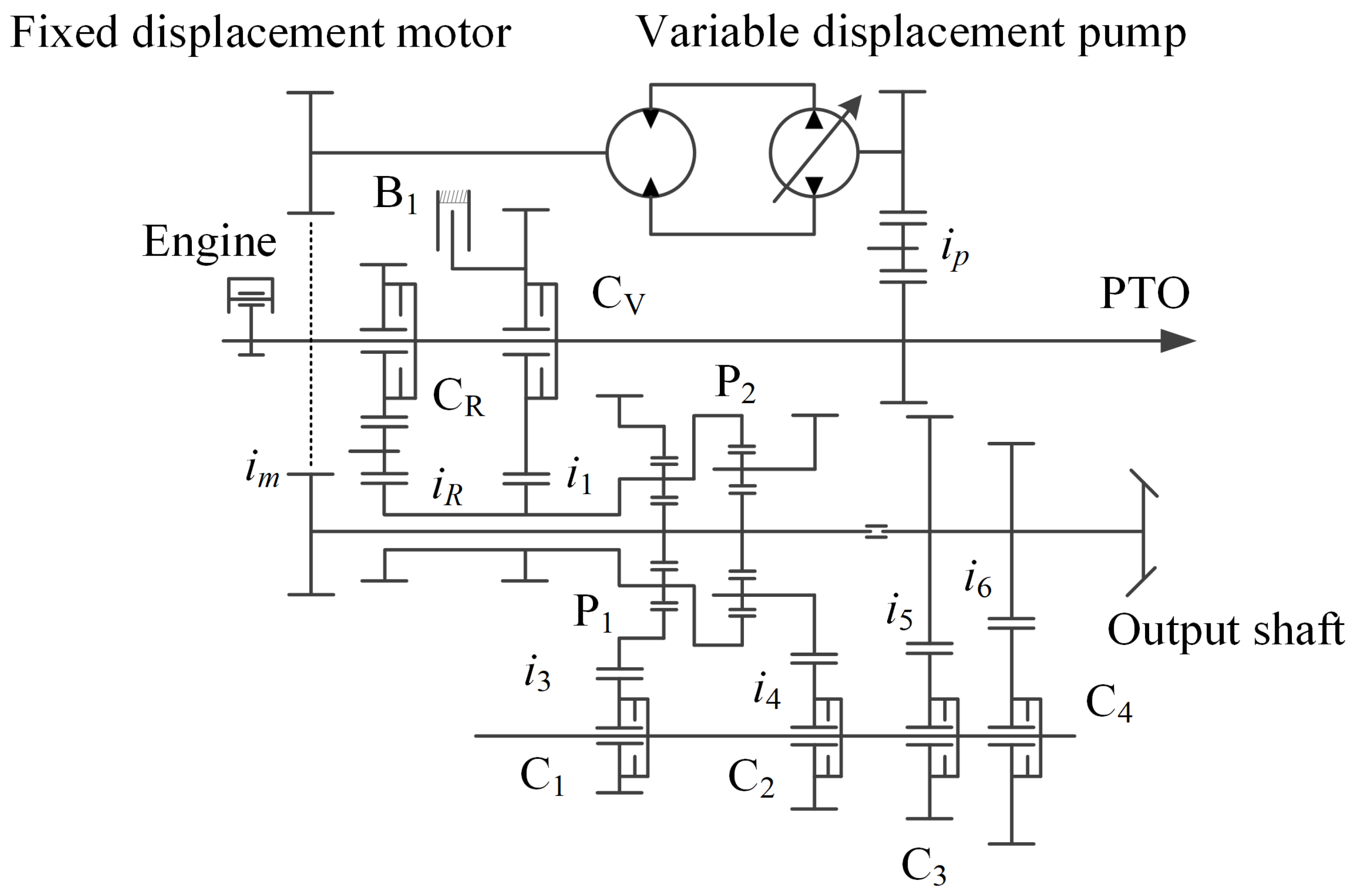
2.1. A Five-Stage HMCVT Designed in This Paper
The five-stage HMCVT is mainly composed of a variable displacement pump, fixed displacement motor, fixed axis gears (transmission ratio of gear pair is
i1,
iR,
i3,
i4,
i5,
i6,
ip and
im, respectively), wet clutches (C
V, C
R, C
1, C
2, C
3 and C
4, respectively), planetary gear sets (P
1 and P
2, transmission characteristic parameters are
k1 and
k2), and brake B
1, as shown in
Figure 1.
2.2. Working Principle of HMCVT
The HMCVT designed in this paper has five forward sections, one pure hydraulic working section (H
0 section) and four hydraulic power flow and mechanical power flow coupling working section (HM
1~HM
4 section). The schematic diagram of power flow in different stages is shown in
Figure 2. The red line in
Figure 2 represents the transmission route of the power flow in the current working mode.
In the H0 section mode, the carrier of planetary gear set P1 is locked because of the brake B1 working. The engine output power is input to the sun gear of the planetary gear set P1 only through a variable displacement pump, fixed displacement motor, front gear pair of pumps and rear gear pair of motors. The power is then input to the output shaft by the ring gear of planetary gear set P1, gear pair i3 (wet clutch C1 engaged) and i5 (wet clutch C3 engaged).
In HM1~HM4 section mode, the engagement of wet clutch CV leads to the engine output power input to the carrier of planetary gear set P1 and the ring gear of P2 through gear pair i1. The other part of the engine output power is input to the variable displacement pump through the gear pair ip, and then input to the gear sun of planetary gear set P1 and P2 through the fixed displacement motor and gear pair im (the gear sun of planetary gear set P1 and P2 is designed to be fixed on the same drive shaft). Finally, the power is input to the output shaft through the gear pair i3 (or i4) and gear pair i5 (or i6) by the engagement and separation of wet clutch C1 (or C2) and C3 (or C4).
In addition, with the same working principle of the forward sections, the HMCVT designed in this paper has 5 backward sections (wet clutch C
R is engaged in this state). The specific working modes logic of HMCVT proposed in this paper is shown in
Table 1 (taking forward sections as an example, if it is the backward stages, only C
V is changed to C
R).
2.3. Variation Characteristics of HMCVT Transmission Ratio
According to the speed calculation formula of planetary carrier, ring gear and sun gear of the planetary gear mechanism [
21], the variation characteristics of the HMCVT transmission ratio at each working section are derived as follows:
In the formula, , , , and are the transmission ratios of H0, HM1, HM2, HM3 and HM4, respectively. is the displacement ratio.
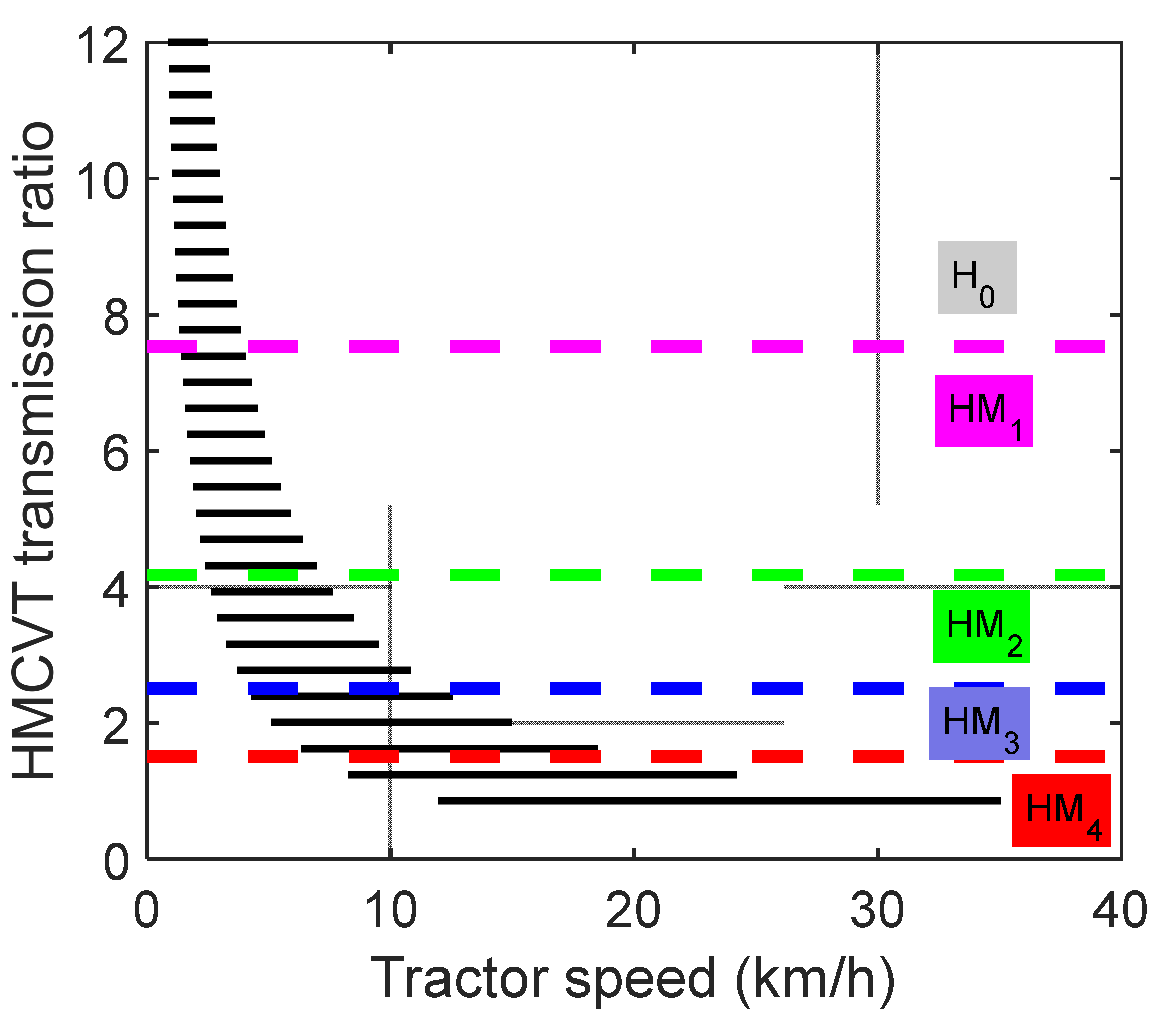
2.4. Matching of Tractor Speed and HMCVT Transmission Ratio
Considering the variety of tractor working types (low speed working conditions mainly include rotary tillage, ditching, bulldozing and so on; medium–high speed working conditions mainly include plowing, harrowing, sowing, cultivation, harvesting, road transportation and so on), the tractor working types are often divided by driving speed. According to the introduction of this paper, the design of a tractor transmission system generally adopts the geometric principle. Based on the research of Chen [
22], Ni et al. [
19] and Sun [
23], this paper sets the speed of a tractor at low-speed operating conditions (corresponding to H
0 section) at 0–4 km/h, at medium–low-speed operating conditions (corresponding to HM
1 section) at 4–7.2 km/h (the ratio is 1.80), at medium-speed operating conditions (corresponding to HM
2 section) at 7.2–12 km/h (the ratio is 1.67), at medium– high-speed operating conditions (corresponding to HM
3 section) at 12–20 km/h (the ratio is 1.67) and at high-speed operating conditions (corresponding to the HM
4 section) at 20–35 km/h (the ratio is 1.75). The ratio of speed variation range of each section above is approximate (the ratio is about 1.72).
The working speed range of the tractor engine is set to 750–2200 rpm, the rolling radius of the driving wheel is 0.976 m, and the total transmission ratio of other transmission mechanisms is 26.866. The calculation formula of tractor speed is as follows. Speed calculation formula reference [
7,
24,
25]. Because the research is oriented to the conceptual design stage of the novel HMCVT proposed in this paper, the research ignores the wheel slip.
where
is the driving speed of tractor;
is the radius of wheels;
is the working speed of engine;
is the total transmission ratio of other transmission mechanism; and
is the transmission ratio of HMCVT.
Based on the speed design of geometric principle and combined with Equation (6), the target transmission ratio range of each working section of HMCVT is matched.
2.5. Optimal Design Method Based on Geometric Principle and Considering the Intersection Position of Each Working Section
The standard design method based on geometric principle makes the ratio of the maximum transmission ratio and the minimum transmission ratio of each HMCVT working section approximately equal, so as to match the transmission design parameters (the transmission ratio of each gear pair and the characteristic parameters of planetary gear mechanism) by solving the equation. The equation to be solved is as follows:
where
is the maximum transmission ratio of HM section;
is the minimum transmission ratio of HM section; and
is the common ratio.
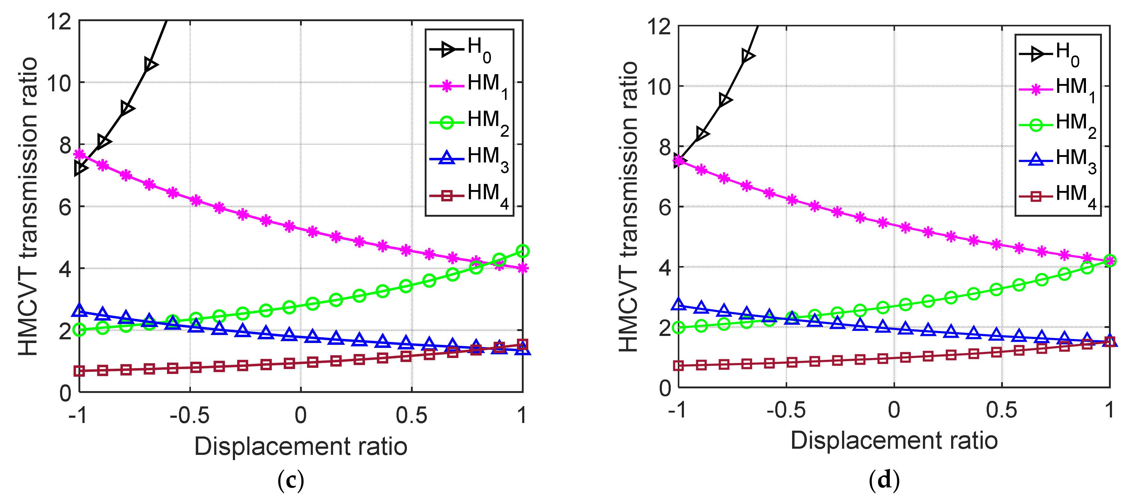
Apparently, the value of
and
is critical. According to Equations (1)–(5), the transmission ratio of each HMCVT working section is a monotonic function of displacement ratio
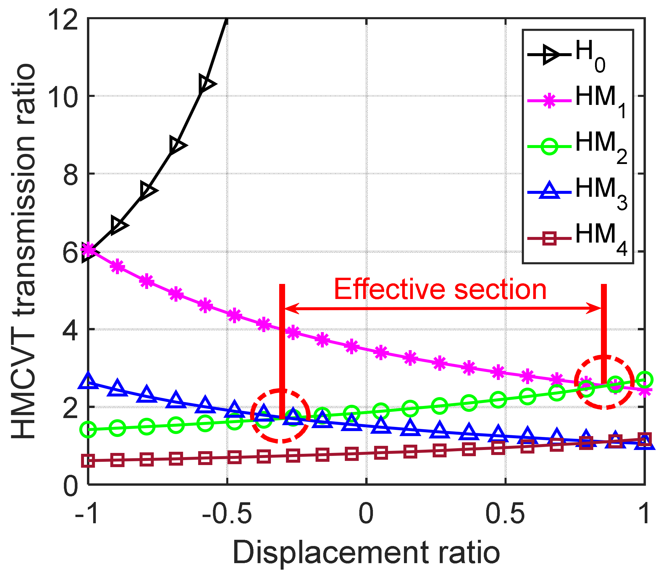
. For HMCVT, the variation characteristics of the transmission ratio at each working section intersect each other (
Figure 3). This makes the tractor transmission ratio change continuously and reduces the vibration and shock during shift. Therefore, the effective section of transmission ratio for each HMCVT section is the area in the intersection of left and right ends (for example, in
Figure 3, the effective section for the HM
2 section is marked). In summary, the transmission ratio of each HMCVT working section is not necessarily the maximum or minimum when the displacement ratio
. Uncertainty of the intersection position of the HMCVT sections leads to difficulty in solving Equation (7) (the traditional geometric design method often assumes that when the displacement ratio
, the transmission ratio of each HMCVT working section has the maximum or minimum value).
In this paper, a new optimization design method based on geometric principle is proposed, which considers the intersection position of each working section. Based on the original design individuals to be optimized (the transmission ratio of each gear pair and the characteristic parameters of a planetary gear mechanism), this method introduces four intersection position individuals (the five-stage HMCVT proposed in this paper has four intersections). The intersection position individual is the value of the displacement ratio
at the intersection of each HMCVT working stage. The individuals to be optimized are:
where
is the x-coordinate of the intersection of H
0 and HM
1, HM
1 and HM
2, HM
2 and HM
3, and HM
3 and HM
4 (the value of the displacement ratio
).
The optimization design objective function
of the proposed method in this paper is:
where
is the displacement ratio at
intersection;
is the design target value at
intersection;
is the transmission ratio at
for the HMCVT low-speed section; and
is the transmission ratio at
for the HMCVT high-speed section.
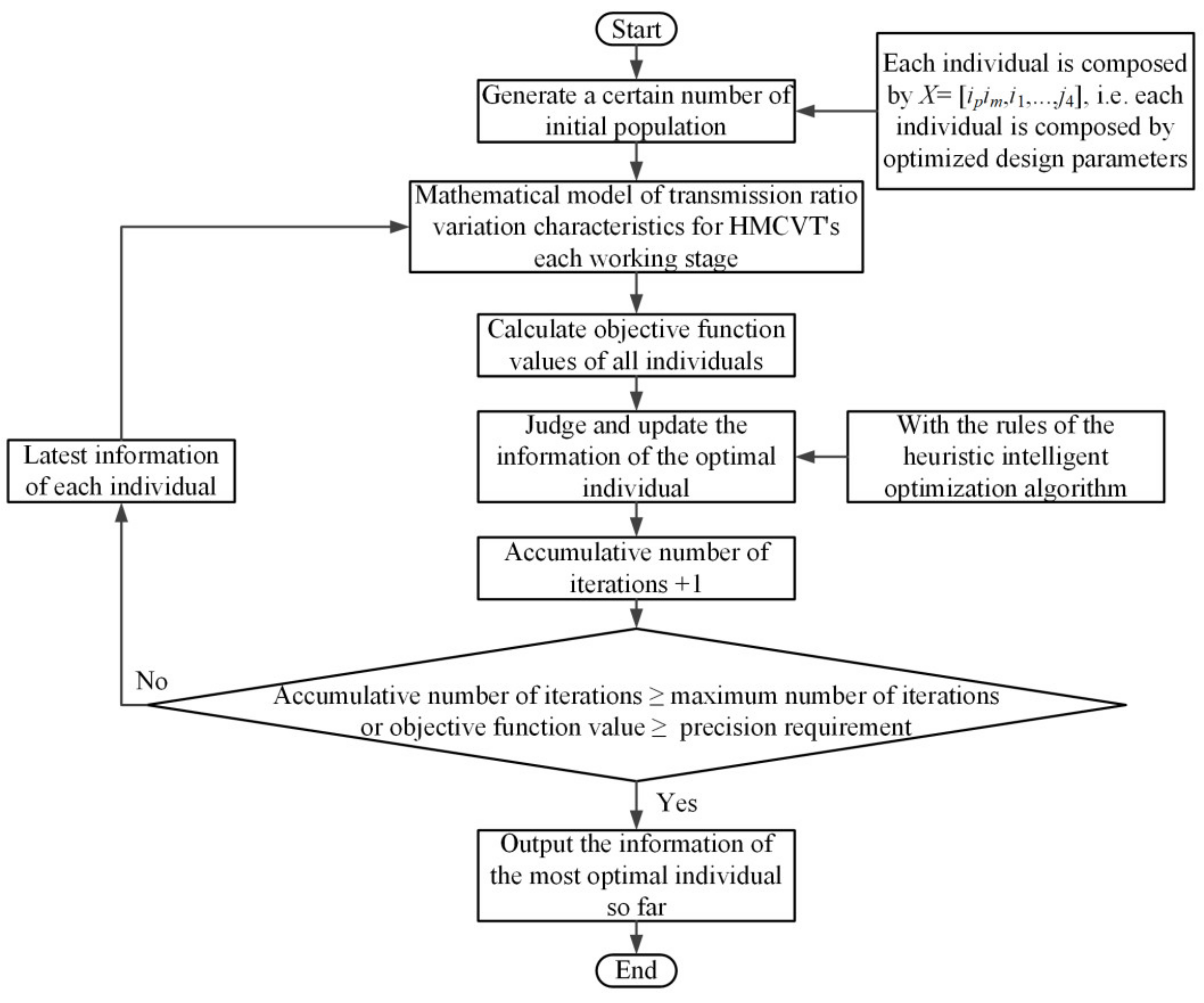
In the optimization process, the HMCVT’s minimum transmission ratio corresponding to the maximum speed of the tractor as the constraint condition, the flow chart of the proposed method in this paper is shown in
Figure 4.
2.6. Algorithm for Optimization Design
The proposed HMCVT in this paper has a complex structure and many parameters to be optimized. The objective function of this optimization problem is nonlinear. The heuristic optimization algorithm [
25,
26,
27,
28] is suitable for solving a series of complex engineering problems. The genetic algorithm (GA) is combined with the optimization design method proposed in this paper to complete the matching of transmission ratio parameters. GA is an evolutionary algorithm with the survival of the fittest as the basic rule of iterative computation and evolution. It is suitable for multi-parameter and multi-objective engineering optimization problems. To further improve the effect of parameter optimization design, this paper uses I-GA, which has been proposed and verified in previous studies [
29]. The I-GA improves the convergence speed and accuracy of the algorithm mainly from several aspects. The I-GA screen and delete the super individuals in the population. Adaptive changes of the population size, crossover and mutation probabilities are introduced into the I-GA.
The range of population size is set as 1000–2000. The rest of the algorithm parameters are consistent with the reference [
29]. The values of
can be seen in
Section 3.1 in the paper, which are 7.53, 4.18, 2.51 and 1.51, respectively.
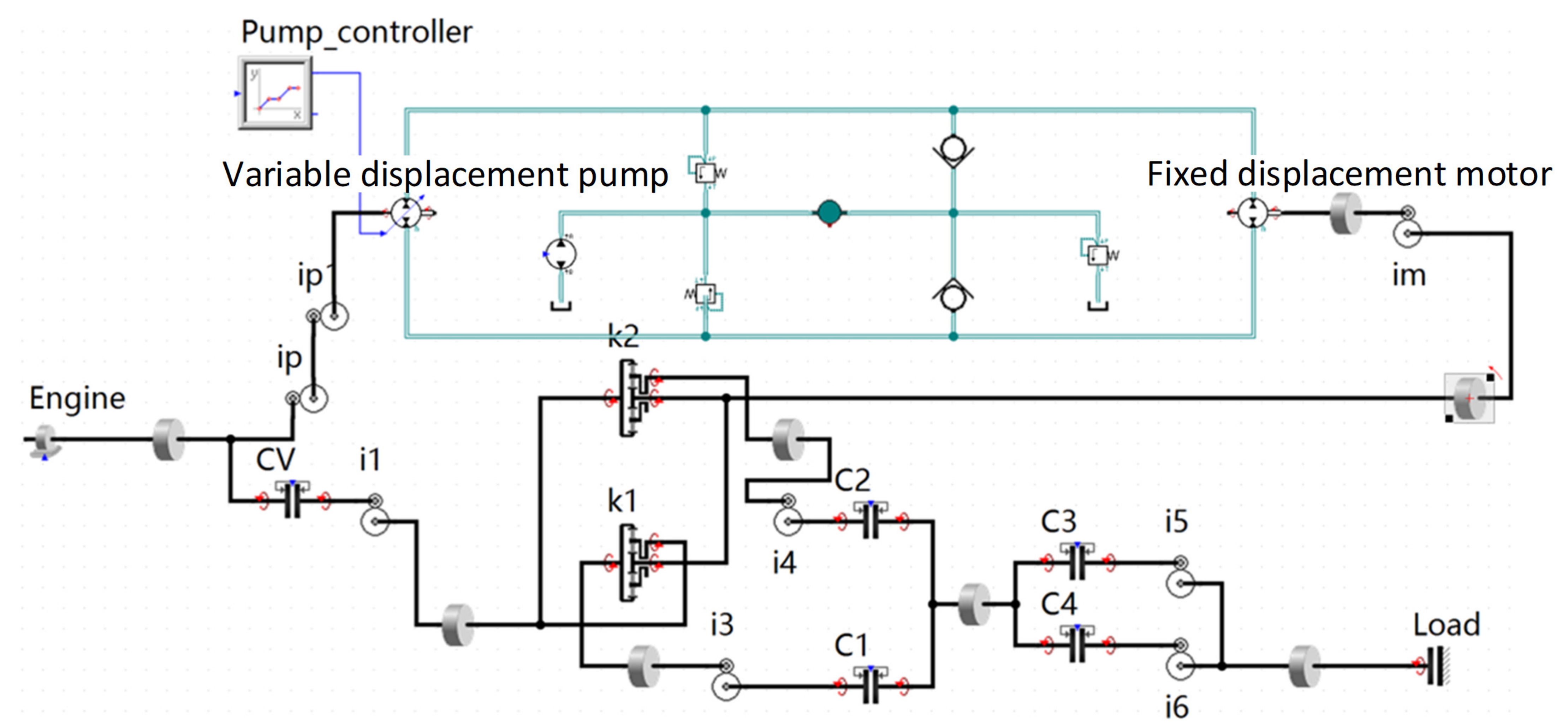
2.7. Simulation Test Platform Based on Simulation X Software
Simulation X is a multidisciplinary and widely used simulation software. Its modular modeling method is suitable for the research object of this paper. The simulation model of a five-stage HMCVT is built by the built-in planetary gear model, friction load model, fixed axis gear model, clutch model and engine model (
Figure 5).
3. Results and Discussion
3.1. Matching Results of Tractor Speed and HMCVT Transmission Ratio
The variation range of the target transmission ratio at each HMCVT working section and its corresponding relationship with tractor speed are shown in
Figure 6.
According to the calculation results of geometric principle, the target transmission ratios of each HMCVT working section are: 7.53~+∞ (H0 section), 4.18~7.53 (HM1 section), 2.51~4.18 (HM2 section), 1.51~2.51 (HM3 section) and 0.86~1.51 (HM4 section), respectively.
3.2. Results of Transmission Ratio Optimization Design
The transmission parameters of the five-stage HMCVT are optimized by the proposed method. Since the number of decision variables is 12, the design freedom of the expanded objective function is 8. The number of decision variables is greater than the design degrees of freedom of the objective function. Therefore, multiple feasible solutions will be generated after optimization iteration. This paper draws on the design ideas of Kisssoft. There are many feasible solutions in mechanical system design. In this paper, the optimization design method is independently executed three times to obtain three feasible solutions. The results of the three feasible solutions are compared and one of them was selected as the final design scheme of this paper. The results are shown in
Figure 7 and
Table 2.
From
Figure 7 and
Table 2, the three optimization results converge to the same minimum. The application of I-GA in this project has good effect. The algorithm can continuously decline during the iterative process (the initial optimization speed of the algorithm is fast and the optimization speed tends to be gentle in the middle and late stages of the algorithm, but it still has the ability of continuous decline). This effectively avoids the premature phenomenon of the algorithm. After the optimization of three transmission parameters, the HMCVT’s transmission characteristics are consistent with the target characteristics (the mean error is 2.62%, 4.69% and 2.49%, respectively). And the minimum HMCVT transmission ratio is less than 0.86. The maximum speed of the tractor meets the design requirements.
In the first optimization, the ratios of the transmission ratio’s effective section of each HMCVT working section are 1.81, 1.80, 1.50 and 2.10, respectively. In the second optimization, the ratios of the transmission ratio’s effective section of each HMCVT working section are 1.76, 1.86, 1.59 and 2.04, respectively. In the third optimization, the ratios of the transmission ratio’s effective section of each HMCVT working section are 1.80, 1.82, 1.52 and 2.11, respectively. The three optimization results are 1.80, 1.81 and 1.81, respectively; the variances are 0.06, 0.04 and 0.06, respectively (the data fluctuation is small). Therefore, the designed HMCVT basically meets the geometric design requirements.
According to the three optimization design results, the gear pair transmission parameters ipim, i1, i3, i4 and i5 can be designed in a wide range of changes. The i6 mainly works at mid–high-speed and high-speed state of the tractor, and its design range is small and the value is small. The characteristic parameters of the planetary gear that output by the ring gear are smaller (k1 ≤ 2), while the characteristic parameters of the planetary gear that output by the planetary carrier are larger (k2 ≥ 3). Compared with the results of the first and second optimization, the results of the third optimization have a wider range of the displacement ratio’s utilization intervals (the utilization ratio of the displacement ratio’s interval of HM2 and HM3 is 76%, while the interval utilization ratio of the other three working sections is 100%, and the average utilization ratio of the whole working section is 90.4%). Meanwhile, the results of the first optimization and the second optimization are both partial utilization of the displacement ratio’s intervals (the average utilization rates of the whole working section are 82.8% and 85.8%, respectively). In addition, the third optimization result has the smallest error. In summary, the third optimization result is selected as the final design result.
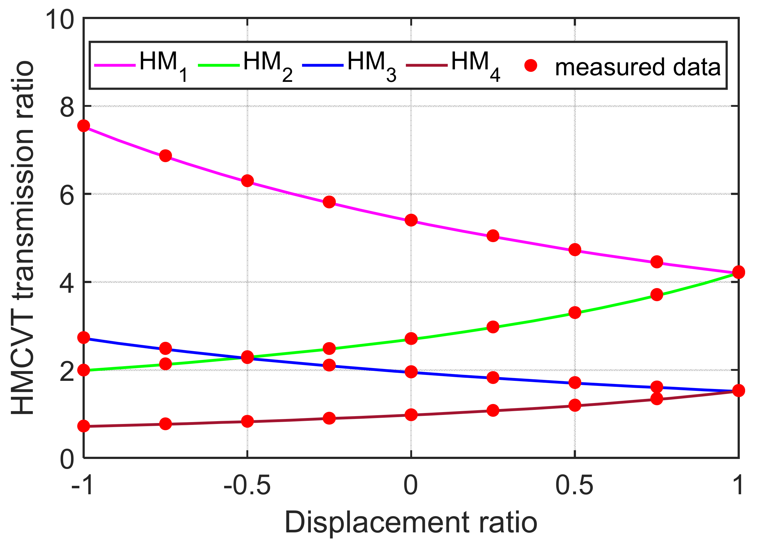
3.3. Simulation Test Verification Based on Simulation X
The H
0 section is a pure hydraulic working section (the hydraulic power flow transmitted only by variable displacement pump and fixed displacement motor in the tractor transmission system), and basically only acts when the tractor starts. The backward-working principle of the HMCVT is consistent with the forward-working principle, and only one idler wheel is added for the transmission. Therefore, the simulation experiment in this paper verifies the transmission ratio characteristics of the hydraulic power flow and mechanical power flow coupling working sections (HM
1, HM
2, HM
3 and HM
4 sections) when the tractor moves forward. Each working section divides the displacement ratio into nine levels (the displacement ratios are −1, −0.75, −0.5, −0.25, 0, 0.25, 0.5, 0.75 and 1, respectively) and carries on each level simulation test one by one, with a total of 36 groups of simulation tests. The verification results are shown in
Figure 8.
According to
Figure 8, the
MAPE (mean absolute percentage error) of transmission ratio characteristics at the HM
1, HM
2, HM
3 and HM
4 sections is 0.41%, 0.57%, 0.85% and 1.06%, respectively. The
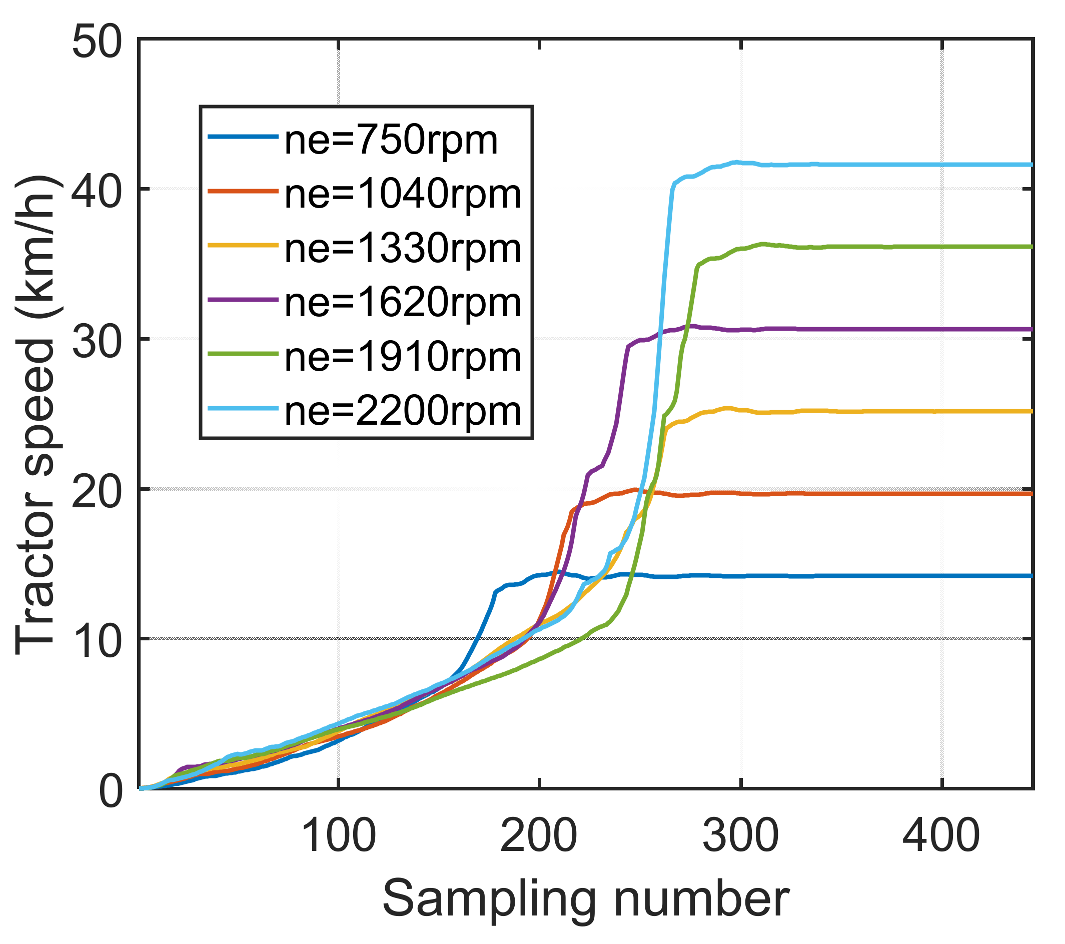
MAPE of all transmission ratio data (a total of 36 simulation tests) is 0.72%. Then set the displacement ratio of the variable displacement pump to −1; clutch C
V, C
1 and C
4 engaged (HMCVT is in the state of minimum transmission ratio); the engine speed is equally divided into six parts within the working speed range (750, 1040, 1330, 1620, 1910 and 2200, respectively). The simulation results based on Simulation X are shown in
Figure 9.
According to
Figure 9, when the engine is at the maximum speed of 2200 rpm, the maximum speed of the tractor reaches 41.62 km/h, which meets the design requirements of the maximum speed of 35 km/h.
4. Conclusions
In this paper, a five-stage HMCVT is proposed for tractors, and a geometric design method for transmission ratio characteristics is proposed based on the intersection position of each working section and I-GA. After the optimization design of transmission parameters, the transmission ratio characteristics of the five working sections change continuously, and there is no discontinuity of transmission ratio characteristics.
The utilization rate of the displacement ratio’s change interval is high and the average utilization rate of the whole working section is 90.4%. The five-stage HMCVT proposed in this paper meets the demand for tractor speed. The optimization design method proposed in this paper is based on I-GA that can flexibly complete the matching of transmission parameters according to geometric principle. The intersection position information of each working section is introduced in the optimization process of transmission parameters, and the problem of the standard method’s solving difficulty caused by the uncertainty of intersection position is solved effectively. The HMCVT transmission characteristics are highly consistent with the target characteristics, the average error of the three solutions is about 3.27%, and the common ratio is about 1.81.
The simulation experiment based on Simulation X verifies the correctness of the design in this paper. The average error of 36 simulation tests is about 0.72%. The maximum driving speed of the tractor is greater than 35 km/h, which meets the design requirements.


