Article

Design and Experiment of Automatic Clip-Feeding Mechanism for Vegetable-Grafting Robot

1
Research Center of Intelligent Equipment, Beijing Academy of Agriculture and Forestry Sciences, Beijing 100097, China
2
National Engineering Research Center of Intelligent Equipment for Agricultural (NERCITA), Beijing 100097, China
3
College of Mechanical and Engineering, Jiamusi University, Jiamusi 154007, China
*
Author to whom correspondence should be addressed.
Agriculture 2022, 12(3), 346; https://doi.org/10.3390/agriculture12030346
Submission received: 13 January 2022 / Revised: 24 February 2022 / Accepted: 24 February 2022 / Published: 28 February 2022
(This article belongs to the Special Issue Recent Advances in Horticultural Grafting)

Abstract

:
Aiming to solve the problems of poor performance and low stability in the automatic clip-feeding of a grafting machine, an automatic clip-feeding mechanism with a precise single-clip discharge mechanism was designed, and a clip-feeding performance test was carried out. Taking the grafting clip of the 2TJGQ-800 type of vegetable-grafting robot as the research object, the clamping-force analysis model of the grafting clip was constructed by ABUQUS finite-element analysis software, and the variation law of clamping force, steel wire diameter, and opening deformation, as well as the calculation equation of clamping force, were obtained. The grafting clip model was verified by mechanical test, and test results showed that the grafting clip with a steel wire diameter of 0.7 mm proved safe and reliable for grafted cucumber and watermelon seedlings; the grafting clip with steel wire diameter of 0.8 mm had a risk of producing injury to grafted cucumber and watermelon seedlings when clamping. The method of single-clip discharge in the inclined discharging slideway was put forward, and the components for clip discharge and clip pushing were designed. The critical thrust for sending out the grafting clip in the clip-feeding slideway was 0.603 N after analyzing the force status of the grafting clip in the clip-feeding slideway. Test results showed that the success rate of automatic clip-feeding reached 98.67% when inclination angle of row-discharging slideway was 50° and the thrust of clip-pushing cylinder (input air pressure of 0.4 MPa) was 8.04 N, which met the technical requirements of mechanical grafting. The inclination of the grafting clip and the damaged clip in the feeding slideway is the main reason for the failure of clip-feeding. The research results can provide theoretical and design references for the innovative research of the automatic clip-feeding mechanism of grafting robots.

1. Introduction

Vegetable grafting is conducive to preventing continuous cropping obstacles and relevant pests and diseases [1,2]. After grafting, the disease resistance of crops is significantly enhanced [3,4], and yield is increased by 20–50%; hence, the technology is widely applied in the world. There is an annual demand for 50 billion grafted seedlings in China, and with the aging of population, there is great demand for technical grafting workers. Moreover, seedling enterprises are in bad need of grafting machines [5,6,7]. The grafting clip, as a key part for grafting vegetables, is used to fix the incision of grafted seedlings to make them fit closely. The mechanical properties of existing grafting clips are still unclear, and there is a lack of reference standards for producers to choose grafting clips [8]. The automatic clip-feeding mechanism is the core mechanism of grafting equipment, and the success or failure of a clip-feeding operation directly affects production efficiency and the quality of grafting [9,10]. Thus, it is particularly important to study the mechanical characteristics of the grafting clip to improve the survival rate of grafted seedlings and the success rate of a clip-feeding mechanism operation.
Scholars and research institutions at home and abroad have attached great importance to the research of automatic clip-feeding mechanisms for vegetable-grafting machinery [11,12,13,14,15,16]. Iseki & Co., Ltd. (Tokyo, Japan) in Japan used a vibrating disk to make the grafting clips horizontal, and the designed clip-feeding mechanism outputs one grafting clip at a time using a horizontal push rod. However, since the force-applying part of the push rod is the upper part of the connection point of the clip, the grafting clip can easily be damaged. The clip-feeding rate is around 95% and the steel ring diameter of the grafting clip is 8 mm, creating the problem of extrusion and damage to melon-grafted seedlings [17,18]. Helper Robotech Co., Ltd. (Gimhae-si, Gyeongsangnam-do, Korea) in Korea developed a horizontal clip-pushing mechanism with an inclined slideway. The grafting clip is transported and discharged into the inclined slideway using a vibrating disk, then pushed out by a horizontal push rod, but the force-application part of the push rod is the steel ring of the clip, which can easily deform. Since the grafting clips are arranged obliquely, when the grafting clips are arranged into the slideway non-horizontally, the clip can easily become stuck and lead to failure in grafting. The clip-feeding rate is around 95%, and the problems of becoming stuck and deformation of the clip is obvious. In this case, it is necessary to stop the device to remove the clip for further operation. This will affect continuous grafting and production of the device [19,20]. China Agricultural University designed a multi-cylinder continuous clip-supply system. The shape of the clip-feeding cylinder is similar to a grafting clip, and can realize the change of a cylinder without interrupting the grafting operation. However, the grafting clip still needs to be manually loaded into the cylinder, undermining its degree of automation. Similar to the clip-feeding mechanism designed by Iseki & Co., Ltd. (Tokyo, Japan) it can achieve a clip-feeding rate of around 92%. In the clip-pushing process, the force on the grafting clip is not uniform, and the clip will easily become damaged [21]. The clip-feeding device of an automatic melon-grafting machine designed by Shenyang Agricultural University includes an inclined linear vibration discharging and feeding device, single discharging arrangement device and clip-pushing device with a success rate of clip-feeding of 92%, showing that operation stability needs to be improved [22]. South China Agricultural University designed a multi-channel conveying device for elastic clip-grafting, which directionally outputs elastic grafting clips using vibrating disks that enter the conveying channel, so that the grafting clips are arranged longitudinally one by one, and the supply operation of three grafting clips at once is completed with the joint operation of a buffer mechanism and a clip-feeding mechanism. The clamping hand of the clip-feeding mechanism clamps the tail of the grafting clip to open it, and the clip-feeding rate can reach about 96%. In this process, there is no need to push the clip; thus, the damage rate of the grating clip is very low [23,24].
To sum up, most existing clip-feeding devices of grafting machines use vibrating disks to sort and output grafting clips, and the horizontal push rods are used to push grafting clips out of the slideway. However, the common problem is clip blockage, caused by inclined clips or deformed spring steel rings in the pushing process, damaging the clip due to uneven force applied by the push rod. In addition, there are few studies on the mechanical properties of grafting clips.
Based on the problems above, in this paper, a 3D model of the grafting clip was created to analyze and determine the clamping-force model of the grafting clip using the finite-element method; then, the mechanical equation of the grafting clip was constructed, and the accuracy of the model was verified by a mechanical test. The method of single-clip arrangement was put forward, the automatic clip-feeding mechanism was designed, the force in the pushing process on the grafting clip was analyzed to determine the critical thrust when pushing the clip, and finally the clip-feeding performance test was carried out. The research results can provide theoretical reference for the design of automatic clip-feeding mechanisms of grafting robots.

2. Materials and Methods

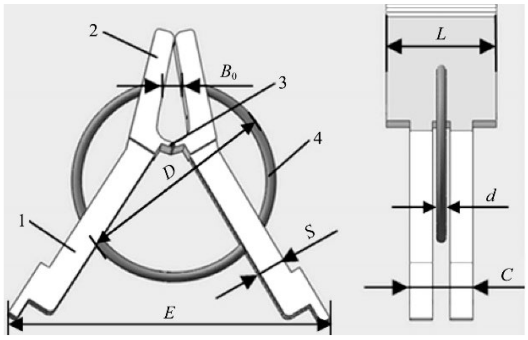
2.1. Parameters of the Grafting Clip
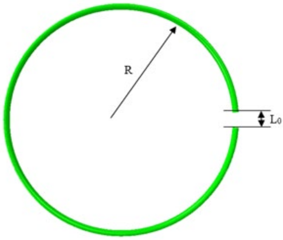
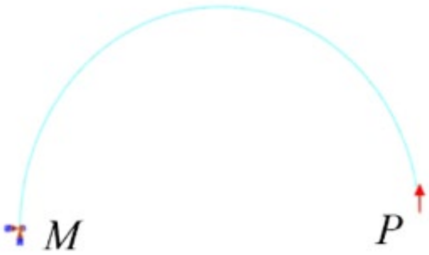
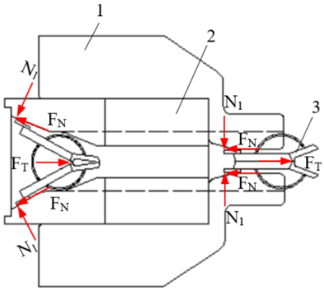
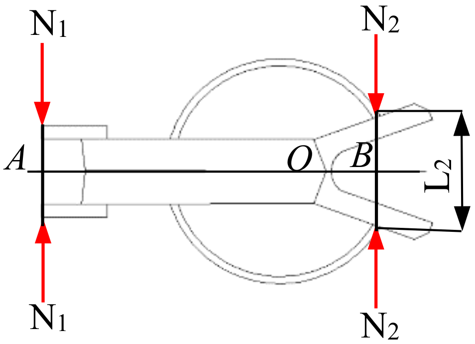
The special grafting clip for the 2TJGQ-800 type of vegetable-grafting robot was selected as the research object, and its structure includes a clip body and a steel ring, as shown in Figure 1. The clip body comprises a clip opening and a clip tail, which are integrally molded by injection molding of PP material. The inner surface of the clamping opening has some spherical protrusions, which increase the friction when clamping. The middle part of the clip tail has a gap for the steel ring to pass through, and the opening end of the steel ring is clamped on the fixed point outside the clip opening to have some pre-tightening pressure, so that the clip body and the steel ring become an integrated body.
Structural parameters of the grafting clip are shown in Table 1. The operation process of the grafting clip is as follows: first, apply some pressure to the clip tail, and the clip opening overcomes resistance from the steel ring and opens. Then, the incision butt joint part of the grafted seedling is put into the clip opening to fit the pressing position of the steel ring. Release the clip tail, and the clip opening clamps the grafted seedlings under the force of the steel ring to complete the operation of clip-feeding.

2.2. Modeling

The clamping force of the grafting clip depends on the mechanical characteristics of the steel ring, which is an annular ring with an opening. Applying an outward tensile load to the opening of the steel ring is equivalent to its clamping force, and the opening of the steel ring using tensile force belongs to static stress-displacement analysis, which is carried out to obtain the relationship between tensile load and displacement change of the steel ring. The stress distribution and change of the internal structure of the steel ring were not studied.
ABUQUS finite-element analysis software was used to establish a model between the displacement of the steel ring opening with different diameters and deformation and change of tensile load, and the relationship between steel ring tension and steel wire diameter and opening displacement deformation was obtained, which is also the force analysis model of the grafting clip. The beam element was used to establish a steel ring model. The diameter d of the steel ring is 15 mm, and the opening L0 of the steel ring is 1 mm. The 3D model was established, as shown in Figure 2. The steel wire diameters are 0.4 mm, 0.5 mm, 0.6 mm, 0.7 mm, 0.8 mm, 0.9 mm, 1.0 mm and 1.1 mm, and the corresponding mechanical models of different steel wire diameters can be obtained by changing the cross-section dimensions in ABAQUS software.
The opening section of the steel ring has a solid boundary, and the section is a solid body. The material characteristics of the steel ring are shown in Table 2.
The steel ring structure and tensile load are symmetrical; hence, half of the model was taken for analysis, as shown in Figure 3. In the figure, M is the symmetry center, and P is the application point of cross-section tensile load.
The symmetry plane of the steel ring is set as a fixed constraint, and a vertical upward displacement load is applied to the open end. According to the maximum distance between the opening ends of the grip, numerical simulation was carried out on a load step moving upwards by 9 mm, with an average of 10 equal parts, and the data of the displacement deformation and tensile load change of the steel ring opening with different steel wire diameters were obtained, as shown in Table 3.
By fitting the data in Table 3, the relationship curve between tensile load and opening displacement variation of the steel ring with wire diameter of 0.4–1.1 mm was obtained, as shown in Figure 4. The figure shows that the tension of steel ring increases with the increase of opening displacement and wire diameter.
The fitting equation of tension force and opening displacement deformation of the steel ring with steel wire diameter of 0.4–1.1 mm is obtained as follows:
When d = 0.4 mm,
F = 0.061483 × Δ L
When d = 0.5 mm,
F = 0.150082 × Δ L
When d = 0.6 mm,
F = 0.311161 × Δ L
When d = 0.7 mm,
F = 0.576357 × Δ L
When d = 0.8 mm,
F = 0.983026 × Δ L
When d = 0.9 mm,
F = 1.574234 × Δ L
When d = 1.0 mm,
F = 2.398725 × Δ L
When d = 1.1 mm,
F = 3.510909 × Δ L
The relationship between the proportional coefficient of displacement deformation ΔL and the diameter of steel wire was calculated, and the results are shown in Figure 5. The proportional coefficient of ΔL increases with the increase of steel wire diameter, and the fitting proportional coefficient is 2.3989·d3.9985.
The tension equation of the steel ring is:
F = 2.3989 x 3.9985 Δ L
which is equivalent to the following equation:
F = 2.4 x 4 L 0.5
where x is the diameter of the steel wire, mm; L is the distance from the opening of the steel ring to the symmetrical center plane, mm.

2.3. Automatic Clip-Feeding Mechanism

The automatic clip-feeding mechanism is an important part of the vegetable-grafting robot, which provides fast clamping and fixing operations for grafted seedlings, and its stability is highly related to the success of grafting. The reason for clip blockage in the clip-feeding mechanism of the existing grafting machine is that the clip is inclined after entering the clip-feeding slideway, avoiding the steel ring from entering the directional slideway after being pushed by the push rod, or the grafting clip is damaged due to uneven stress. The above problems seriously affect stability and production efficiency in operation.

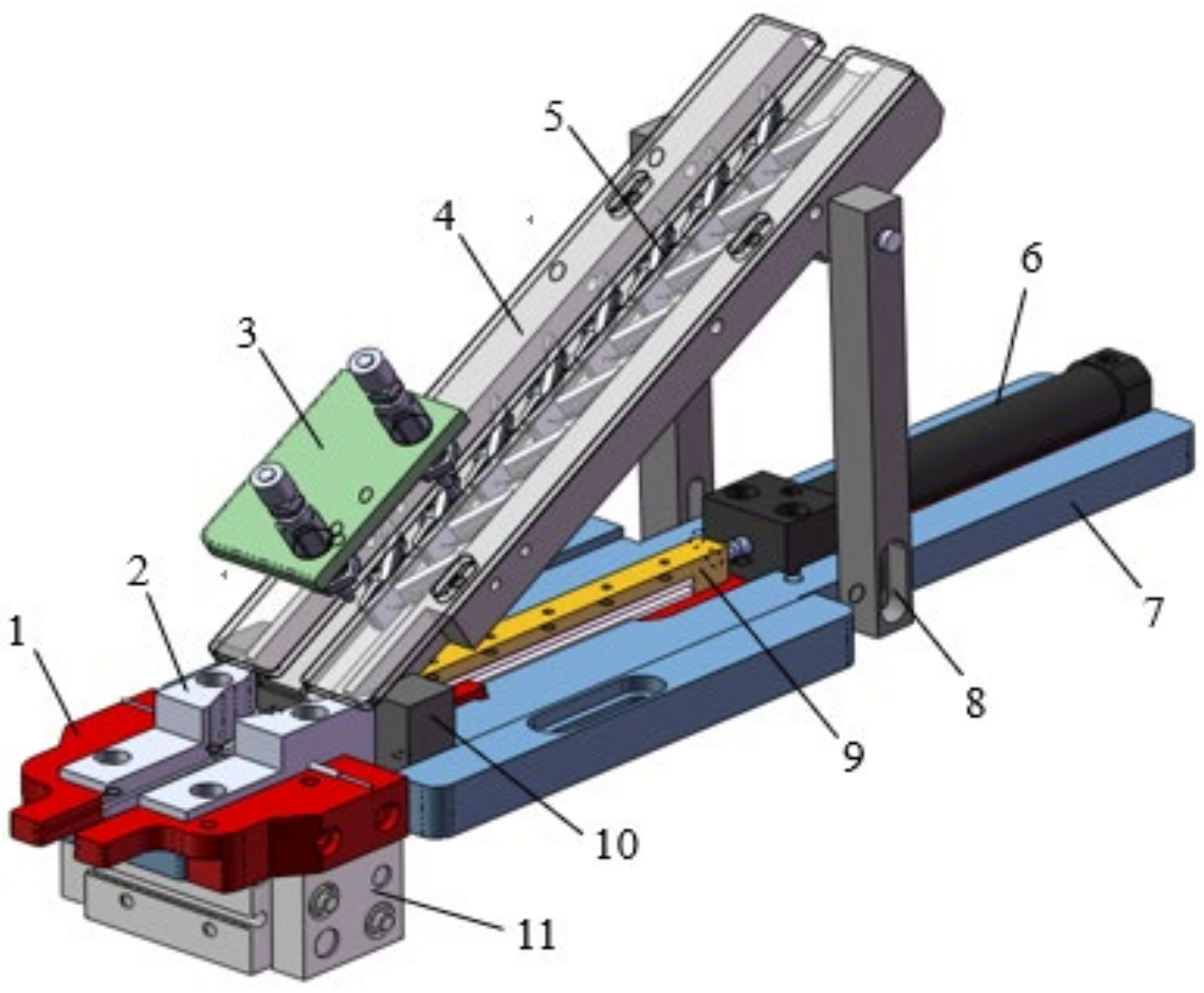
2.3.1. Structure and Working Principle

The automatic clip-feeding mechanism is shown in Figure 6. A clamping hand 1 is installed at the front end of the base 7 through a clamping cylinder 11; a clip-feeding slideway 2 and a supporting block 10 are installed on the base 7 from left to right, and steel ring chutes are arranged inside the clamping hand 1 and the clip-feeding slideway 2 for directional conveying and limiting of grafting clips. The row-discharging slideway 4 is obliquely installed through the support block 10 and the support rod 8, and the upper inlet and the lower outlet of the row-discharging slideway 4 are respectively connected to the vibration feeder and the clip-feeding slideway 2. The clip discharger 3 is installed on the row-discharging slideway 4 with two cylinders to output one grafting clip for the clip sending slideway 2. The push rod 9 is installed in the middle part of the base 7 through a slide rail pull head, and connected and fixed with the piston rod of the clip-pushing cylinder 6, so that the push rod 9 enters the clip-feeding slideway 2 and the clamping hand 1 through the support block 10 to push out the grafting clip.
The working process is as follows: ① The grafting clip opening moves forward from the vibrating feeder into the discharging row slideway at a certain speed to form a queue of inclined grafting clips; ② Two discharging cylinders of the row-discharging part work alternately, and each time one grafting clip is discharged from the grafting clip queue into the clip-feeding slideway; ③ When the grafted seedlings are transported to the corresponding position for grafting, the clip-pushing cylinder extends out to drive the push rod to push the grafting clip into the clamping hand from the clip-feeding slideway, so that the grafting clip opening is opened; ④ The clamping cylinder is opened to drive the clamping hand to open, and the grafting clip breaks away from the clamping hand to clamp the grafted seedlings and complete the clamping action, then another round of clip-feeding operation is started.

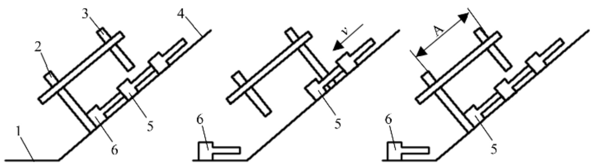
2.3.2. Design of the Clip Discharger Part

The purpose of design of the clip discharger is to discharge grafting clips intermittently from the inclined row-discharging slideway, and the working principle is shown in Figure 7. The clip discharger is installed above the row-discharging slideway, and the initial states of the piston rods of the first discharging cylinder and the second discharging cylinder are in extension and retraction respectively, and the first discharging cylinder blocks the grafting clip queue in the row-discharging slideway. Subsequently, the piston rod of the second discharging cylinder extends into the steel ring of the second grafting clip, while the first discharging cylinder is retracted, and the first grafting clip slides into the buffer area from the inclined row-discharging slideway. Then, the first discharging cylinder and the second discharging cylinder respectively execute extending and retracting actions, so that the second grafting clip enters the initial position of the first grafting clip, to complete single-clip discharge, and the operation circulates in turn.
The type of the row-discharging cylinder is SMC CJPB-15, and the center distance A between the center points of the two discharging cylinders is 35 mm, which can ensure that the piston rod of the first discharging cylinder blocks the first grafting clip, and the piston rod of the second discharging cylinder enters the steel ring of the second grafting clip, thus realizing the precise discharge of one grafting clip in each operation cycle.

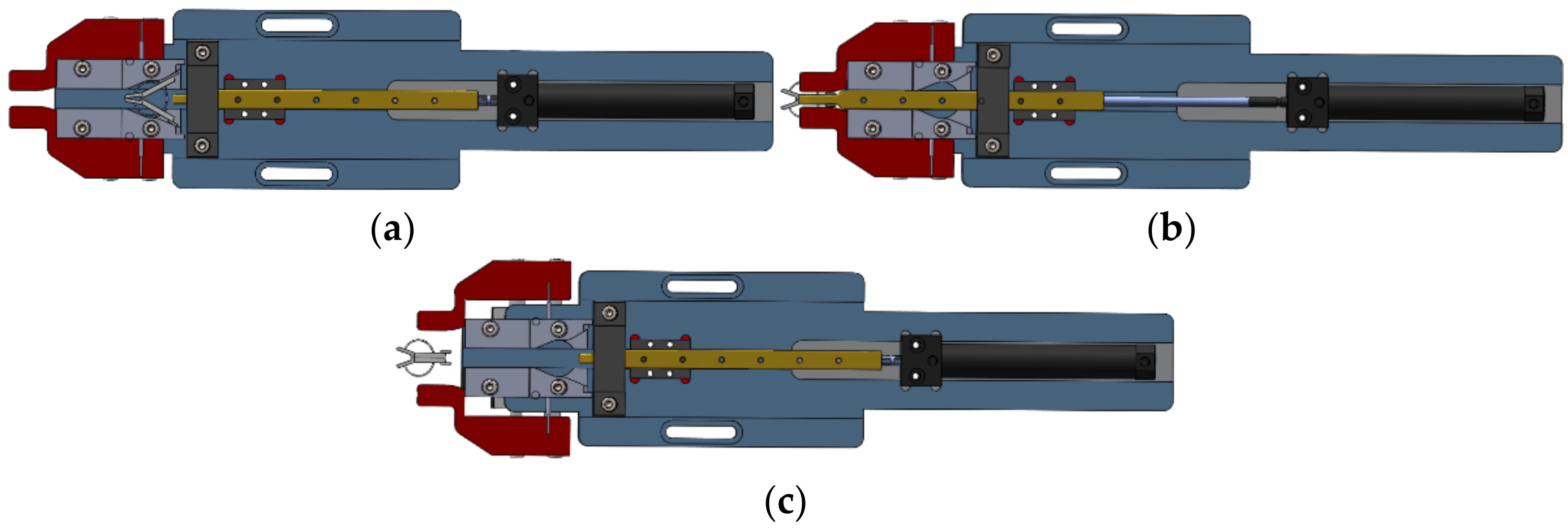
2.3.3. Design of the Clip-Pushing Part

The clip-pushing cylinder drives the push rod to sequentially push the grafting clips at the buffer area into the slideway and the clamping hand from the buffer area of the clip-feeding slideway, so that the grafting clip is completely opened. Then, the clamping cylinder is opened to drive the clamping hand to open, and the grafting clip breaks away from the clamping hand to clamp the grafted seedlings. The process of pushing and feeding is shown in Figure 8. The models of the clip-pushing cylinder and clamping cylinder are SMC CDJ2RA16-85Z-B and AirTAC HFT0-20S, respectively.
The design requirements of the push rod are as follows: ① To reduce the deformation of steel ring or the damage to the clip body in the pushing process, the application point in clip pushing is located on the upper and lower sides of the rear part of the clip opening, to move away from the clip tail and the steel ring; ② the opening angle of the grafting clip entering the clamping hand clip mouth reaches the maximum, so as to ensure that the grafted seedlings can smoothly enter the clip opening and be safely clamped; ③ the push rod moves smoothly to ensure a high success rate of clip pushing and feeding.
The push-rod structure is shown in Figure 9. The front end of the push rod has a transverse gap, so that the front end of the push rod contacts the rear part of the clip opening during the pushing process, and the clip body and the steel ring enter the transverse gap, so that the force on the clip is more uniform and reliable. The length and width of the gap is 18.5 mm and 6.5 mm, respectively. A longitudinal gap is arranged in the middle part of the push rod, which is used for installing the guide rail, and installed on the base with the slide block, thus greatly improving the stability of clip pushing.
To determine the thrust required for a grafting clip to enter the clip-feeding slideway and the clamping hand, the force analysis of the clip-pushing process is explored and shown in Figure 10. The force-application point on the push rod is located at the back of the clip opening of the grafting clip, so it is necessary to overcome the squeezing force and friction force of the clip-feeding slideway on the tail of the clip body, so that the grafting clip can be smoothly pushed into the clamping hand. When the grafting clip moves from the entrance of the clip-feeding slideway to the clamping hand, the squeezing force and friction force on the clip tail gradually increase, and the thrust of the grafting clip entering the clamping hand reaches the maximum.
The balance equation of the grafting clip in the clamping hand is as follows:
F T = 2 F N = 2 μ N 1
where N1 is the pressure on the clip tail from the clamping hand, N; FN is the friction force between the clip-feeding slideway and the clip tail, N; μ is the sliding friction coefficient between grafting clip and clip-feeding slideway.
When the grafting clip opens, it needs to overcome the resistance of the steel ring, and the force analysis is shown in Figure 11. The grafting clip has a symmetrical structure, and the clip tail is squeezed by the hand of the clamping hand, and the clip opening is resisted by the steel ring. The connection point O of the clip body is set as the center, and L2 is the opening distance of the steel ring.
The equation of moment balance between the clip tail and clip opening is:
N 1 l O A = N 2 l O B
then
N 1 = N 2 l O B / l O A
where N1 is the pressure on the clip tail from the clamping hand, and N; N2 is the resistance on the clip opening from the steel ring, N; lOA is the arm of force from N1 to O, mm; lOB is the arm of force from N2 to O, mm.
lOA, lOB and L2 are 17.5 mm, 5.5 mm and 10.15 mm, respectively, in the 3D simulation model of the grafting clip, and the critical thrust FT = 0.603 N is obtained by substituting them into Equations (10), (15) and (13) in turn.

2.4. Experiment and Methods

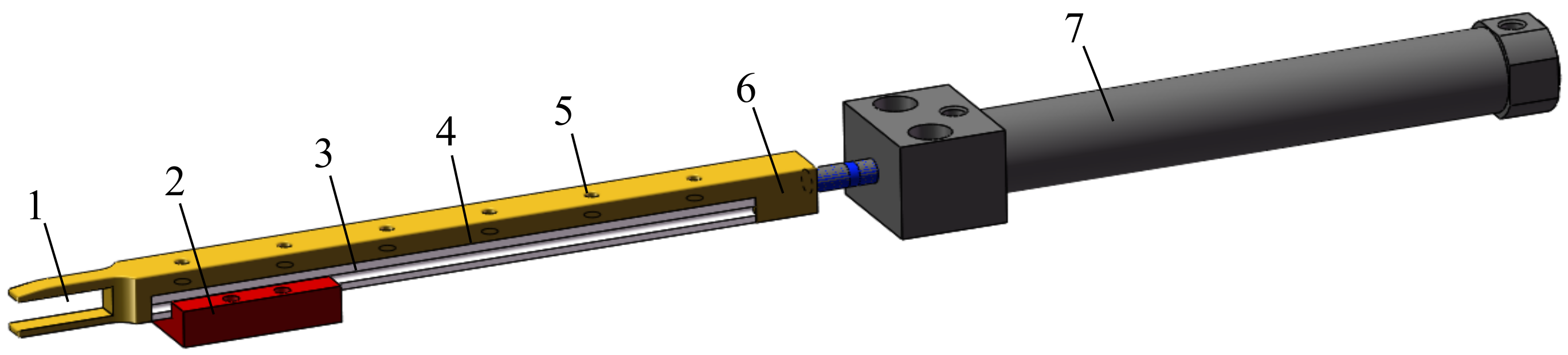
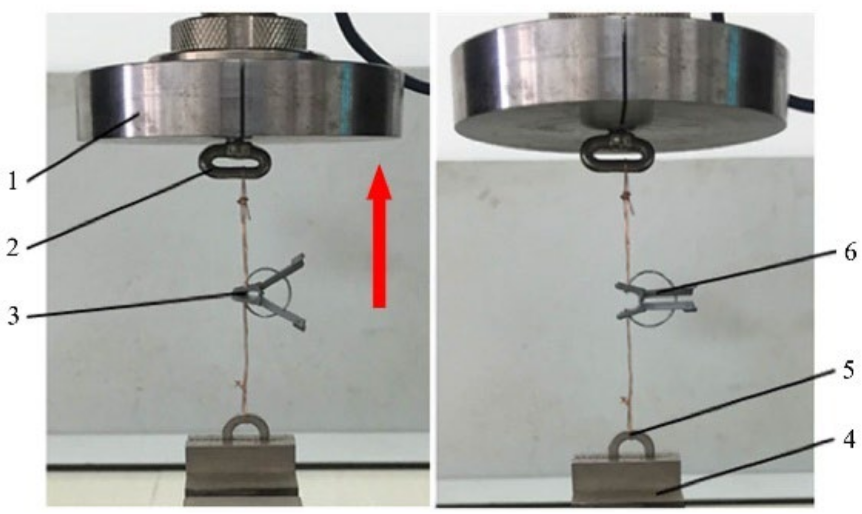
2.4.1. Model Validation

To verify the clamping-force model of the grafting clip, mechanical properties of the grafting clip were tested, and safety characteristics of the grafting clip were comprehensively analyzed regarding the safety and pressure resistance of grafted melon seedlings. Since the steel ring is very small, it is impossible to complete the test directly on the mechanical test device. Therefore, the grafting clip was taken as the object on which to carry out the clip-opening test.
The E43.104 type of mechanical testing machine was used in the test. The grafting clip with a steel wire diameter of 0.7 mm was selected as the test object. Small holes are opened on both sides of the external fixing points of the steel ring and the clip, and the clip is fixed with the upper pull ring and the lower pull ring, respectively, with copper wire, as shown in Figure 12. The mass of grafting clip is about 1 g, without considering the influence of gravity on tensile force, and the number of samples prepared is 30.
Test process is as follows: ① set the state when the pull head goes up to the clip opening and the clip opening and the clip is not opened as the initial value, and reset the tensile load; ② the pull head goes up at a speed of 0.5 mm/s to stretch the clip opening at a uniform speed; ③ when the left and right clamping tails are in a parallel state, stop stretching; at this time, the opening angle of the clip is the largest. The computer automatically records the tensile load and the change of the clip displacement, as shown in Figure 13.
As can be seen from Figure 13, the tensile load with displacement of 0–0.3 mm increases rapidly, the tensile load with displacement of 0.3–5 mm increases steadily and continuously, and the tensile load with displacement greater than 5 mm increases sharply and then continues to increase. Through observation, it can be obtained that in the initial stage of clip opening, the tensile load needs to overcome the resistance from the steel ring and the friction between the copper wire and the clip. In the later stage of clip opening, torsional deformation occurs at the joint of the clip body, which leads to a sharp increase in tensile load before a decrease and a continuous increase.
The regression equation of tensile load and clamp displacement is as follows:
y = 1.3579 x + 1.3947
The coefficient R2 = 0.9924 indicates that the fitting degree of the equation is high.

2.4.2. Experiment Clip-Feeding

Automatic clip-feeding includes clip discharge and feeding. The inclination angle of the row-discharging slideway is the influencing factor on the smooth sliding of the grafting clip into the entrance of clip-feeding slideway, and the thrust from the clip-pushing cylinder is the influencing factor for the smooth pushing of the grafting clip into the clamping hand. The purpose of the test was to study the influence of the inclination angle of the row-discharging slideway and the thrust of the clip-pushing cylinder on the success rate of the clip-feeding mechanism, and to determine the clip-feeding operation parameters.
The test device is shown in Figure 14. The upper part of the support rod is connected to the row-discharging slideway through a shaft; the lower part of the support rod has a U-shaped hole for fixing with the base, and the inclination angle β of the row-discharging slideway can be changed by adjusting the installation height of the support rod. Tests show that the sliding friction angle of the grafting clip in the row-discharging slideway was 20°. When β is higher than 20°, the grafting clip can be smoothly discharged; when β is 60°, the clip discharge speed is too fast, so that the clip would bounce up and incline to one side. In this case, clip-feeding will not be smoothly operated. Therefore, the adjustment range of β was set to 30–50°, to meet the requirements of clip discharge. The output thrust from the clip-pushing cylinder is related to input air pressure. When the threshold thrust in pushing the clip is 0.603 N and the input pressure is 0.6 MPa, the output thrust from the clip-pushing cylinder is 12.06 N, showing an excessively high impact force and damaging the clip. Within the input air pressure range of 0.3 MPa–0.5 MPa, the output thrust of the clip-pushing cylinder is 6.03 N–10.05 N, which can meet the requirements of clip-pushing. Therefore, input air pressure is adjusted within the range of 0.3 MPa–0.5 MPa.

3. Results and Discussion

3.1. Model Validation

The compressive resistance of the grafted seedlings refers to the maximum safe pressure that can be borne under external extrusion. The compressive resistance of grafted cucumber and watermelon seedlings was tested. Based on the seedling stem length in the direction of clamping, the opening displacement deformation of the clip was calculated when clamping seedlings, and substituted in Equations (10) and (11); then, the simulated clamping force and tested clamping force were obtained. Finally, the safety and accuracy of the model of the grafting clip was further compared and analyzed. The model can be used to optimize the steel ring diameter of the grafting clip for different types of grafted seedlings.
Comparison and analysis was made on the safety-pressure resistance of the grafted seedlings, the clamping-force model of grafting clips, and the tensile test of clips. The safety-pressure resistance of grafted seedlings was calculated based on the one with smaller pressure resistance of rootstock and scion [25], and grafting clips with 0.7 mm and 0.8 mm steel wire diameters were selected. The results are shown in Table 4.
It can be seen from Table 4 that the simulated clamping forces of grafting clips with a steel wire diameter of 0.7 mm on grafted seedlings of cucumber and watermelon are 1.94 N and 1.87 N, which are less than their safe pressure resistance. The simulated clamping forces of grafting clips with a steel wire diameter of 0.8 mm on cucumber- and watermelon-grafted seedlings were 3.32 N and 3.19 N, which are close to their safety and pressure resistance, and there was the risk of clamping injury. The experimental clamping forces of the grafting clip with a steel wire diameter of 0.7 mm on cucumber- and watermelon-grafted seedlings were 2.58 N and 2.41 N, respectively, which are less than the simulated clamping forces, indicating that the friction between the copper wire and the clip should be overcome in the test process. Therefore, the use of grafting clips with steel wire diameter of 0.7 mm to fix cucumber-grafted seedlings is suggested, and this model can be used to analyze and calculate the mechanical characteristics of the grafting clips.
It can be shown through analysis that if the clamping force from the grafting clip on the grafted seedlings is higher than the pressure-resistance force, the stem of the seedlings may be damaged, affecting graft healing and survival. Only when the clamping force of the grafting clip is lower than the pressure-resistance force of the seedlings can it ensure the safe fixation of grafted seedlings. First, the pressure-resistance force of 50 cucumber- and watermelon-grafted seedlings was measured. At present, there are two types of grafting clip on the market, with diameters of 0.7 mm and 0.8 mm. Based on the measured pressure-resistance force of cucumber and watermelon seedlings, the clamping force of the two types of grafting clips on the seedlings was calculated based on the grafting clip model, to determine if the two types of clips cause damage to the seedlings or not. Test results showed that the grafting clip with a diameter of 0.7 mm is safe and reliable to fix cucumber and watermelon seedlings, but the crafting clip with a diameter of 0.8 mm may cause damage to the seedlings. However, for the grafting clips with a diameter below 0.7 mm (clips with diameter of 0.3 mm, 0.4 mm, 0.5 mm, 0.6 mm can be customized by manufacturers), subsequent tests are required to see if any of them can help the grafted seedlings survive better. In addition, a variety of seedlings and seedling age may also affect test results. The grafting clip model proposed in this paper can be used to analyze the clamping and damage results of the clip on grafted seedlings, hoping to offer reference to the optimization of grafting clips and new designs. More importantly, it can offer reference for analysis of the operation parameters of automatic the clip-feeding mechanism and the improving clip-feeding rate.

3.2. Experiment Clip-Feeding

The above two factors (inclination angle of the discharging slideway and clip-pushing cylinder thrust) were taken as influencing factors to study the clip-feeding rate. Three levels of inclination angle of the slideway, i.e., 30°, 40° and 50°, were selected, and the input air pressure of the clip-pushing cylinder of 0.3 PMa, 0.4 MPa, and 0.5 MPa with corresponding clip-pushing cylinder thrust of 6.03 N, 8.04 N, and 10.05 N were selected to carry out the two-factor and three-level tests. Without considering the interaction effect of the factors, each group of tests was carried out 100 times and repeated three times. Thus, each group of test includes 300 and 2700 repeats of testing all for nine groups of tests. The statistical results of the average success rate of clip-feeding were obtained, and are shown in Table 5. Successful clip-feeding means that the grafting clip smoothly enters the clip-feeding slideway from the clip-discharging slideway and is successfully pushed into the clamping hand. Failed clip-feeding means the clip sticking and damage to the grafting clip.
It can be seen from the analysis that the failure of clip-feeding is due to the inclination or damage on the clip body when the grafting clip enters the entrance of the clip-feeding slideway from the row-discharging slideway, and the steel ring cannot smoothly enter the steel ring limit groove of the clip-feeding slideway when pushing the clip, resulting in clip blockage. Therefore, ensuring the horizontal state of the grafting clip is key to improving the success rate of clip-feeding. Adjusting the inclination angle of the discharging slideway can provide enough discharging speed for the grafting clip to enter the entrance of the clip-feeding slideway and ensure the horizontal posture of the grafting clip.
The test results were analyzed by variance, and the results are shown in Table 6. The thrust from the clip-pushing cylinder on the success rate of clip-feeding is not significant at α = 0.05. Since the thrust from the clip-pushing cylinder is far greater than the critical thrust of clip pushing, this can ensure that the grafting clip is pushed out smoothly. The influence of the inclination angle of the row-discharging slideway on the success rate of clip-feeding is extremely significant in the phenotype of α = 0.01. When the inclination angle of the row-discharging slideway reaches 50° and the thrust from the clip-pushing cylinder is 8.04 N, the sliding speed of the grafting clip entering the clip-feeding slideway is improved, and the grafting clip is in a horizontal state to a greater extent. The success rate of clip-feeding is 98.67%, which can meet the technical requirements of automatic grafting. When the inclination angle of the row-discharging slideway reaches 50°, the thrust from the clip-pushing cylinder is 10.05 N, and the success rate of clip-feeding is 98%. Because the input pressure of each driving cylinder reaches 0.5 MPa, the vibration of the automatic clip-feeding mechanism is strong.
The clip-feeding device developed by Iseki & Co., Ltd. in Japan discharges the grafting clips in a horizontal direction through the vibration disk, and the pushing rod contacts with the upper part of the clip mouth when pushing the clip. In this way, the clip may easily become damaged due to uneven force on it with a clip-feeding rate of 95%. The clip-feeding mechanism developed by Chinese Agricultural University realizes manual clip discharge into the clip cylinder in a vertical way, and the clip-pushing method is similar to that designed by the Iseki & Co., Ltd. in Japan. However, the grafting clip is poor in quality, resulting in serious clip damages and a low clip-feeding rate of 92% with low working efficiency. The clip-feeding mechanism developed by Helper Robotech Co., Ltd. in Korea discharges the grafting clip into an inclined slideway using a vibration disk; however, the clip may easily become inclined in entering the slideway, and the pushing rod may contact with the steel ring of the clip, causing clip sticking and achieving a clip-feeding rate of only 90%. The clip-feeding mechanism developed by Shenyang Agricultural University is similar to the product of Helper Robotech Co., Ltd. in Korea in structure, and both mechanisms can realize a clip-feeding rate of 92%, showing that the working performance was not significantly improved.
The automatic clip-feeding mechanism designed in this paper includes the clip discharge unit and clip-pushing unit. Compared with existing commercialized system, its working performance and stability has been improved, mainly in the following two aspects: ① through adding a precise clip discharge unit on the clip discharge unit, it realizes single-clip discharge in the slideway, and keeps the grafting clip at a horizontal status and reduces the probability of clip sticking; ② there is a horizontal opening at one end of the pushing rod (no. 1 in Figure 9), which contacts with the upper and lower parts of the rear part of the clip, so that the force on the grafting clip is more uniform, reducing the possibility of clip damage. Moreover, the pushing rod and clip-feeding cylinder are installed on the base through cooperation between the slideway and sliding block, thus enhancing the stability of the clip-pushing process.
Compared with the clip-feeding mechanism on the existing grafting machine, the precision row clip of single grip through the row-discharging slideway realizes horizontal clip pushing. The designed push-rod structure makes the application point on the grafting clip more uniform, reduces the damage on the clip due to uneven stress, and comprehensively solves the technical problems of clip blockage. However, it is still necessary to further optimize the structural parameters of the clamping hand and the clip-pushing slideway.

4. Conclusions

(1)
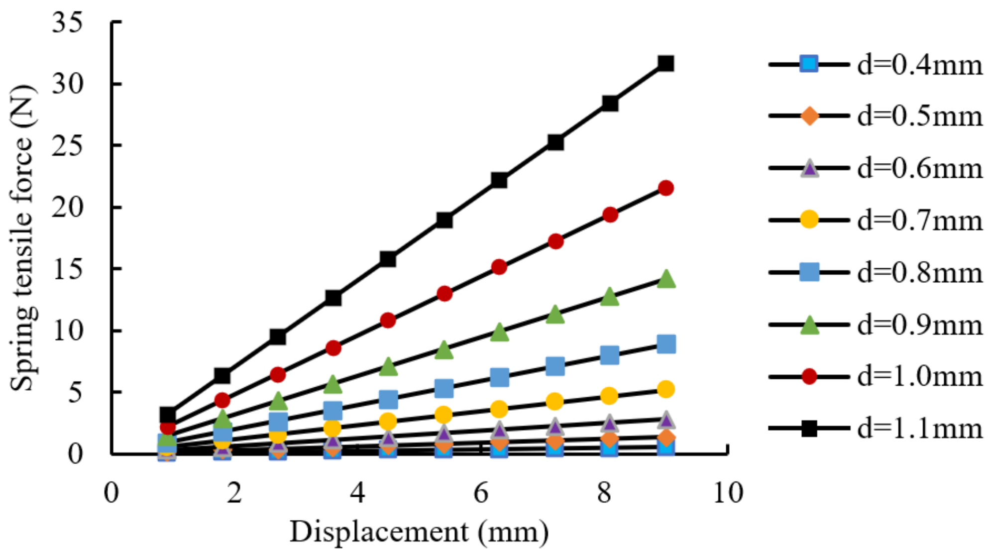
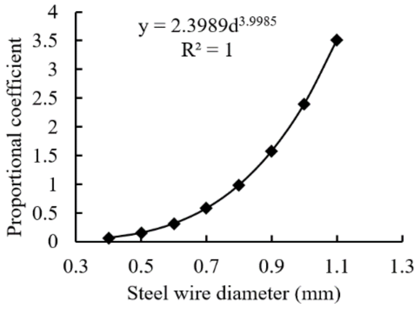
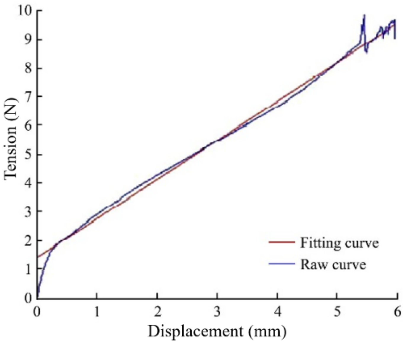
The finite-element analysis method was applied in ABUQUS to build the clamping-force analysis model of the grafting clip, and the accuracy of the model was verified via mechanical tests on the grafting clip. The variation law of tensile load and clip-opening displacement of the steel ring with different steel wire diameters was obtained, and the tension equation of the steel ring was established. A testbed for the mechanical characteristics of tensile load on the grafting clip was built, and the regression equation between tensile load and clip-opening displacement was analyzed and obtained. Based on the analysis of grafted seedling safety and pressure resistance, and the analysis model of the grafting clip clamping force and the data of the tensile test on the clip, it is concluded that the grafting clip with a steel wire diameter of 0.7 mm was safe and reliable to clamp melon-grafted seedlings, and the grafting clip with a steel wire diameter of 0.8 mm had the risk of clip damage. This model can be used to analyze and calculate the mechanical characteristics of the grafting clip.
(2)
An automatic clip-feeding mechanism with a single-clip discharger was designed. The working principle and structural parameters of the clip discharger and pushing parts were analyzed, and the application point of the push rod to the grafting clip is more uniform, which solves the problem of damage on the grafting clip caused by uneven stress. The critical thrust on the grafting clip was 0.603 N, which provides a theoretical basis for improving the success rate of automatic clip-feeding.
(3)
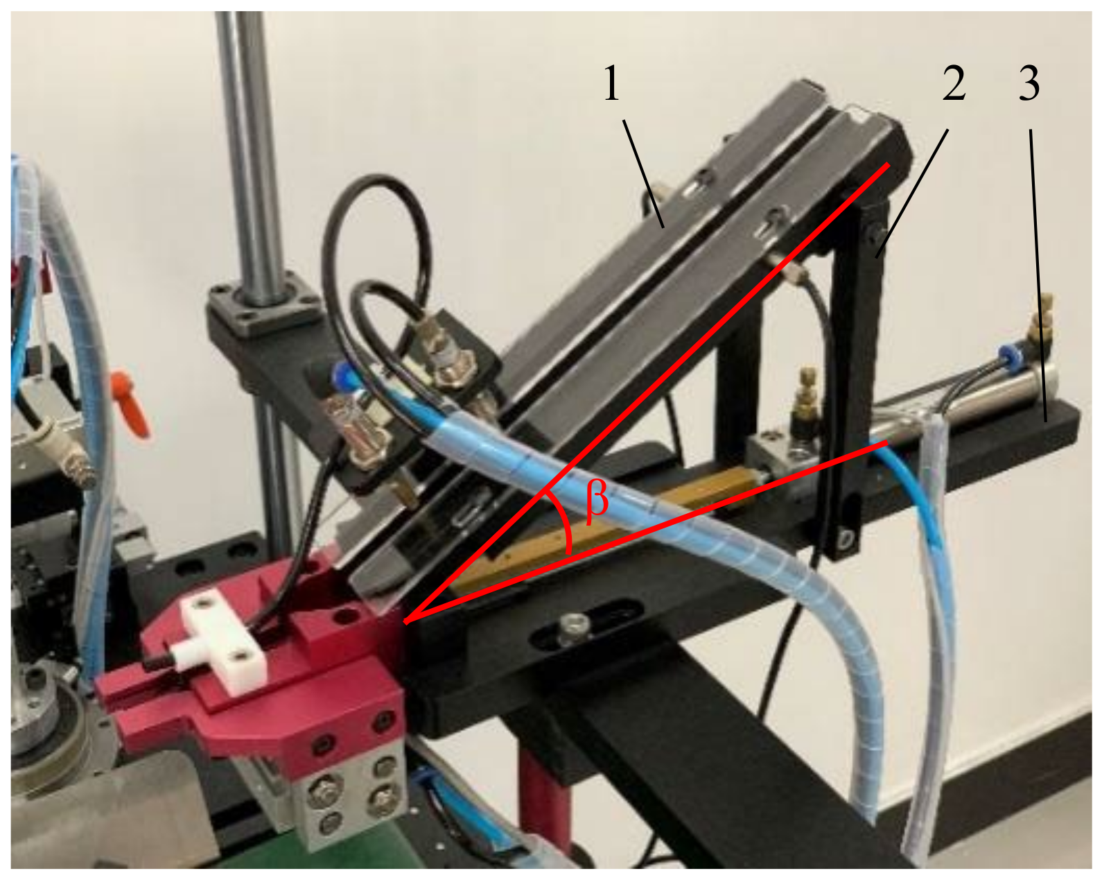
The designed automatic clip-feeding mechanism was used to carry out the clip-feeding test, and the results show that the inclination angle of the row-discharging slideway is the main factor affecting the clip-feeding success rate, and the thrust from the clip-pushing cylinder had no significant influence on the clip-feeding success rate. When the inclination angle of the row-discharging slideway was 50° and the thrust from the clip-pushing cylinder was 8.04 N, the grafting clip stayed in a horizontal state after entering the clip-feeding delivery slideway from the row-discharging slideway, and the success rate of clip-feeding achieved 98.67%, which met the technical requirements of automatic grafting. The reason for the failure of clip-feeding is that the grafting clip ring does not enter the directional chute of the clip-feeding slideway chute, so it is necessary to further optimize the structure of the clip-feeding slideway.

5. Patents

Kai Jiang, Qian Zhang, Cuiling Li, Xiu Wang, Jian Song. The clip-feeding mechanism and its application method, Application Number: ZL 201811641253.1 China National Intellectual Property Administration.

Author Contributions

Conceptualization, L.C.; methodology, K.J. and X.W.; software, K.J. and Y.G.; validation, K.J., W.G. and W.H.; formal analysis, K.J. and L.C.; investigation, K.J. and L.C.; data curation, K.J.; writing—original draft preparation, K.J.; writing—review and editing, X.W.; visualization, K.J. and Y.G.; supervision, X.W.; project administration, K.J. and W.G.; funding acquisition, K.J. All authors have read and agreed to the published version of the manuscript.

Funding

This is research was financially supported by the National key Research and Development Program of China (2019YFE0125200), the National Nature Science Foundation of China (Grant No. 32171898), the BAAFS Innovation Ability Project (KJCX20220403) and the China National Agricultural Research System (CARS-25).

Institutional Review Board Statement

Not applicable.

Informed Consent Statement

Not applicable.

Data Availability Statement

The data presented in this study are available on demand from the first author at (jiangk@nercita.org.cn).

Conflicts of Interest

The authors declare no conflict of interest.

References

  1. Liu, C.J.; Lin, W.G.; Feng, C.R.; Wu, X.S.; Fu, X.H.; Xiong, M.; Bie, Z.L.; Huang, Y. A New Grafting Method for Watermelon to Inhibit Rootstock Regrowth and Enhance Scion Growth. Agriculture 2021, 11, 812. [Google Scholar] [CrossRef]
  2. Bantis, F.; Koukounaras, A.; Siomos, A.S.; Dangitsis, C. Impact of scion and rootstock seedling quality selection on the vigor of watermelon–interspecific squash grafted seedlings. Agriculture 2020, 10, 326. [Google Scholar] [CrossRef]
  3. Guan, W.J.; Zhao, X.; Hassell, R.; Thies, J. Defense Mechanisms Involved in Disease Resistance of Grafted Vegetables. Horticulture 2012, 47, 164–170. [Google Scholar] [CrossRef] [Green Version]
  4. Turhan, A.; Ozmen, N.; Kuscu, H.; Serbeci, M.S.; Seniz, V. Influence of rootstocks on yield and fruit characteristics and quality of watermelon. Hortic. Environ. Biotechnol. 2012, 53, 36–341. [Google Scholar] [CrossRef]
  5. Zhu, C.Y.; Yue, D.J. Production status and technology trend of vegetable seedling industry in China. Agric. Eng. Technol. 2019, 39, 34–38. [Google Scholar]
  6. Liu, M.C.; Ji, Y.H.; Wu, Z.H.; He, W.M. Current situation and development trend of vegetable seedling industry in China. China Veg. 2018, 11, 7. [Google Scholar]
  7. Wang, L. Current situation and development of factory seedling production in China. Agric. Eng. Technol. 2017, 37, 15–19. [Google Scholar]
  8. Jiang, K.; Wang, J.W.; Zhang, Q.; Li, C.L.; Wang, X. Mechanical characteristics analysis and test of a spring-loaded grafting clip. Int. Agric. Eng. J. 2018, 27, 61–72. [Google Scholar]
  9. Li, J.; Zhang, T.Z.; Chu, J.; Zhang, L.B.; Zhang, W.B.; Yin, Q. Design and Experiment of Grafting-clip Transporting Mechanism of Full Automatic Grafting Machine for Whole-row Vegetable Seedlings. Trans. Chin. Soc. Agric. Mach. 2017, 48, 14–20. [Google Scholar]
  10. Jiang, K.; Zhang, Q.; Wang, X.; Feng, Q.C.; Guo, R. Design for Automatic Sequencing and Supplying Device for Grafting Clips. Trans. Chin. Soc. Agric. Mach. 2012, 43, 256–261. [Google Scholar]
  11. Pardo-Alonso, J.L.; Carreño-Ortega, Á.; Martínez-Gaitán, C.C.; Fatnassi, H. Behavior of Different Grafting Strategies Using Automated Technology for Splice Grafting Technique. Appl. Sci. 2020, 10, 2745. [Google Scholar] [CrossRef]
  12. Zhang, K.L.; Chu, J.; Zhang, T.Z.; Yin, Q.; Kong, Y.S.; Liu, Z. Development Status and Analysis of Automatic Grafting Technology for Vegetables. Trans. Chin. Soc. Agric. Mach. 2017, 48, 1–13. [Google Scholar]
  13. Jiang, K.; Zheng, W.G.; Zhang, Q.; Guo, R.; Feng, Q.C. Development and experiment of vegetable grafting robot. Trans. Chin. Soc. Agric. Eng. 2012, 28, 8–14. [Google Scholar]
  14. Comba, L.; Gay, P.; Aimonino, D.R. Robot ensembles for grafting herbaceous crops. Biosyst. Eng. 2016, 146, 227–239. [Google Scholar] [CrossRef]
  15. ISO Group. Available online: http://www.iso-group.nl (accessed on 20 December 2021).
  16. Conic System. Available online: http://www.conic-system.com (accessed on 20 December 2021).
  17. Ohkoshi, T.; Kobayashi, K. Development of automatic seedling feeding device for cucurbits grafting robot (Part1)-Evaluation of automatic stock feeder. J. Jpn. Soc. Agric. Mach. Food Eng. 2013, 75, 100–107. [Google Scholar]
  18. Kobayashi, K.; Sasaya, S. Study on Automation of Seedlings Feeding for Grafting Robot for Cucurbitaceous Vegetables (Part2). Agric. Mach. Food Eng. 2007, 69, 70–77. [Google Scholar]
  19. Kang, D.H.; Lee, S.Y.; Kim, J.K.; Park, M.J.; Son, J.K.; Yun, S.W. Development of an Automatic Grafting Robot for Fruit Vegetables using Image Recognition. Prot. Hortic. Plant Fact. 2019, 28, 322–327. [Google Scholar] [CrossRef]
  20. Kim, H.M.; Hwang, S.J. Comparison of Pepper Grafting Efficiency by Grafting Robot. Prot. Hortic. Plant Fact. 2015, 24, 57–62. [Google Scholar] [CrossRef]
  21. Yang, L.; Liu, C.Q.; Zhang, T.Z. Design and experiment of vegetable grafting machine with double manipulators. Trans. Chin. Soc. Agric. Mach. 2009, 40, 175–181. [Google Scholar]
  22. Tian, S.B.; Yang, J.F.; Wang, R.L. Optimization experiment of operating parameters on vibration sorting-clip device for vegetable grafting machine. Trans. Chin. Soc. Agric. Eng. 2014, 30, 9–16. [Google Scholar]
  23. Xie, Z.J.; Gu, S.; Chu, Q.; Li, B.; Fan, K.J.; Yang, Y.L.; Yang, Y.; Liu, X.G. Development of a high -productivity grafting robot for Solanaceae. Int. J. Agric. Biol. Eng. 2020, 13, 82–90. [Google Scholar] [CrossRef]
  24. Gu, S.; Xie, Z.J.; Chu, Q.; Lv, Y.J.; Li, B.; Hu, J.S.; Peng, Y.P. A Multi-Channel Conveying Device for Elastic Fixing Clip; Application Number: 201611167450.5; China National Intellectual Property Administration: Guangzhou, China, 2016.
  25. Jiang, K.; Chen, L.P.; Feng, Q.C.; Zhang, Q.; Cao, L.L. Mechanical grafting characteristics of melon seedlings. Int. Agric. Eng. J. 2020, 29, 250–257. [Google Scholar]
Figure 1. Three-dimensional model of the grafting clip: 1. Clip tail. 2. Clip opening. 3. Connection point. 4. Steel ring. B0 is clip hold cross-range of initial clipping position; D is diameter of detachable coils; E is initial cross-range of the back of clip; S is thickness of the back of clip; L is Clip hold seedling length; d is diameter of steel wire; C is width of the back of clip.
Agriculture 12 00346 g001
Figure 2. The steel ring model.
Agriculture 12 00346 g002
Figure 3. The exerting constraint and load of the steel ring.
Agriculture 12 00346 g003
Figure 4. The curve of spring tensile force and displacement change of steel wire with different diameters.
Agriculture 12 00346 g004
Figure 5. Relationship between proportional coefficient and steel wire diameter.
Agriculture 12 00346 g005
Figure 6. The automatic clip-feeding mechanism: 1. Clamping hand. 2. Discharging slideway. 3. Clip discharger. 4. Discharging slideway. 5. Grafting clip. 6. Clip-pushing cylinder. 7. Base. 8. Support rod. 9. Push rod. 10. Support block. 11. Clamping cylinder.
Agriculture 12 00346 g006
Figure 7. Working principle of precise clip discharge: 1. Clip-feeding slideway. 2. The first discharging cylinder. 3. The second discharging cylinder. 4. Discharging slideway. 5. The second grafting clip. 6. The first grafting clip.
Agriculture 12 00346 g007
Figure 8. Clip-pushing and -feeding process: (a) Putting grafting clip into the entrance of clip-discharging slideway; (b) Grafting clip is pushed out by push rod; (c) Grafting clip is released by clamping hand.
Agriculture 12 00346 g008
Figure 9. Structure of the push rod: 1. Transverse Gap. 2. Pull head. 3. Guide Rail. 4. Longitudinal Gap. 5. Guide Rail Fixing Hole. 6. Push-Rod Fixing Hole. 7. Clip-Pushing Cylinder.
Agriculture 12 00346 g009
Figure 10. Force analysis of clip pushing: 1. Clamping hand. 2. Clip-feeding slideway. 3. Grafting clip.
Agriculture 12 00346 g010
Figure 11. Force analysis of the grafting clip.
Agriculture 12 00346 g011
Figure 12. Stretching process of clip jaw: 1. Tension-compression head. 2. Loop of stretching up. 3. Grafting clip. 4. Platform support. 5. Loop of stretching down. 6. The maximum angle of clip hold.
Agriculture 12 00346 g012
Figure 13. Relation curve between tensile and displacement.
Agriculture 12 00346 g013
Figure 14. Test device: 1. Discharging slideway. 2. Support rod. 3. Base.
Agriculture 12 00346 g014
Table 1. Structural parameters of the grafting clip.
ItemsParameters
StructureUnitary
MaterialPP
Diameter of detachable coils D (mm)15.0
Diameter of steel wire d (mm)0.7
Clip hold seeding length L (mm)10.0
Thickness of the back of clip S (mm)2.18
Width of the back of clip C (mm)5.15
Clip hold cross-range of initial clipping position B0 (mm)1.37
Initial cross-range of the back of clip E (mm)26.0
Clip mass (g)1.0
Friction coefficient between clip and slideway μ0.364
Table 2. Material properties of the steel ring.
ItemsParameters
Materials304 stainless steel
Poisson’s ratio v0.3
Elastic modulus (MPa)194,020
Yield strength σ0.2 (MPa)205
Tensile strength σb (MPa)520
Density ρ (g·cm−3)7.93
Table 3. Variation of spring force and opening displacement variation of steel wire with different diameters.
Displacement ΔLTensile Load F (N)
D = 0.4 mmD = 0.5 mmD = 0.6 mmD = 0.7 mmD = 0.8 mmD = 0.9 mmD = 1.0 mmD = 1.1 mm
0.90.0553350.1350740.2800450.5187210.8847241.4168102.1588503.159820
1.80.1106690.2701480.5600901.0374401.7694502.8336204.3177006.319640
2.70.1660030.4052220.8401351.5561602.6541704.2504306.4765509.479460
3.60.2213380.5402961.1201802.0748803.5388905.6672408.63540012.639300
4.50.2766720.6753701.4002202.5936004.4236207.08405010.79430015.799100
5.40.3320070.8104441.6802703.1123205.3083408.50086012.95310018.958900
6.30.3873410.9455181.9603103.6310406.1930609.91767015.11200022.118700
7.20.4426761.0805902.2403604.1497707.07779011.33450017.27080025.278500
8.10.4980101.2156702.5204004.6684907.96251012.75130019.42970028.438400
9.00.5533451.3507402.8004505.1872108.84724014.16810021.58850031.598200
Table 4. Verification results of grafting clip model.
Test ObjectDiameter of Grafted
Seedlings
(mm)
Safety-Pressure Resistance
(N)
Displacement Variable ΔL (mm)Simulated
Clamping Force
(N)
Tested Clamping Force
(N)
Clip OpeningSteel RingD = 0.7 mmD = 0.8 mmD = 0.7 mm
Grafted cucumber seedlings3.12 ± 0.103.31 ± 0.121.753.3751.943.322.58
Grafted watermelon seedlings2.86 ± 0.123.73 ± 0.151.493.2451.873.192.41
Table 5. Clip-feeding test results.
No.Inclination Angle of
Discharging Slideway
(°)
Clip-Pushing
Cylinder Thrust
(N)
Input Air Pressure of Clip-Pushing Cylinder
(MPa)
Success Rate of Clip-Feeding
(%)
1306.03 0.382.33
2308.04 0.483.67
33010.05 0.584.33
4406.03 0.392.00
5408.04 0.493.00
64010.05 0.592.33
7506.03 0.396.33
8508.04 0.498.67
95010.05 0.598.00
Table 6. Results of variance analysis.
Difference SourceSum of SquaresDfMean SquareF–ValueSignificance
Inclination angle of discharging slideway310.582155.29501.7318.00 (α = 0.01)
Thrust by the clip-pushing cylinder4.2622.136.896.94 (α = 0.05)
Error1.2440.31
Total316.088
Publisher’s Note: MDPI stays neutral with regard to jurisdictional claims in published maps and institutional affiliations.

