

Parameter Optimization and Experiment of a Seed Furrow Cleaning Device for No-Till Maize Seeding
 and
and
Abstract
:1. Introduction
2. Materials and Methods
2.1. Mechanized No-Till Seeding of Maize
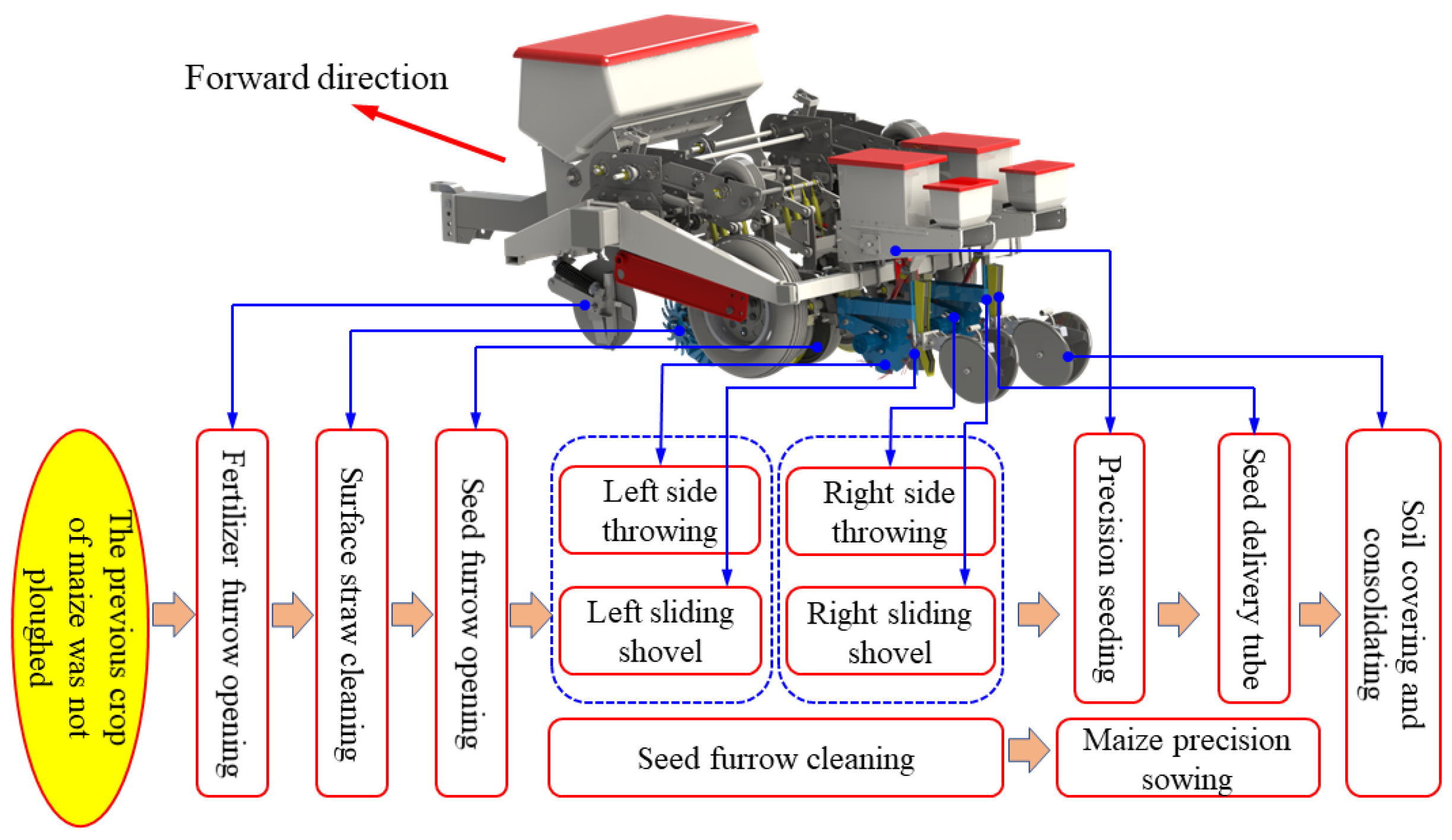
2.1.1. Process Route
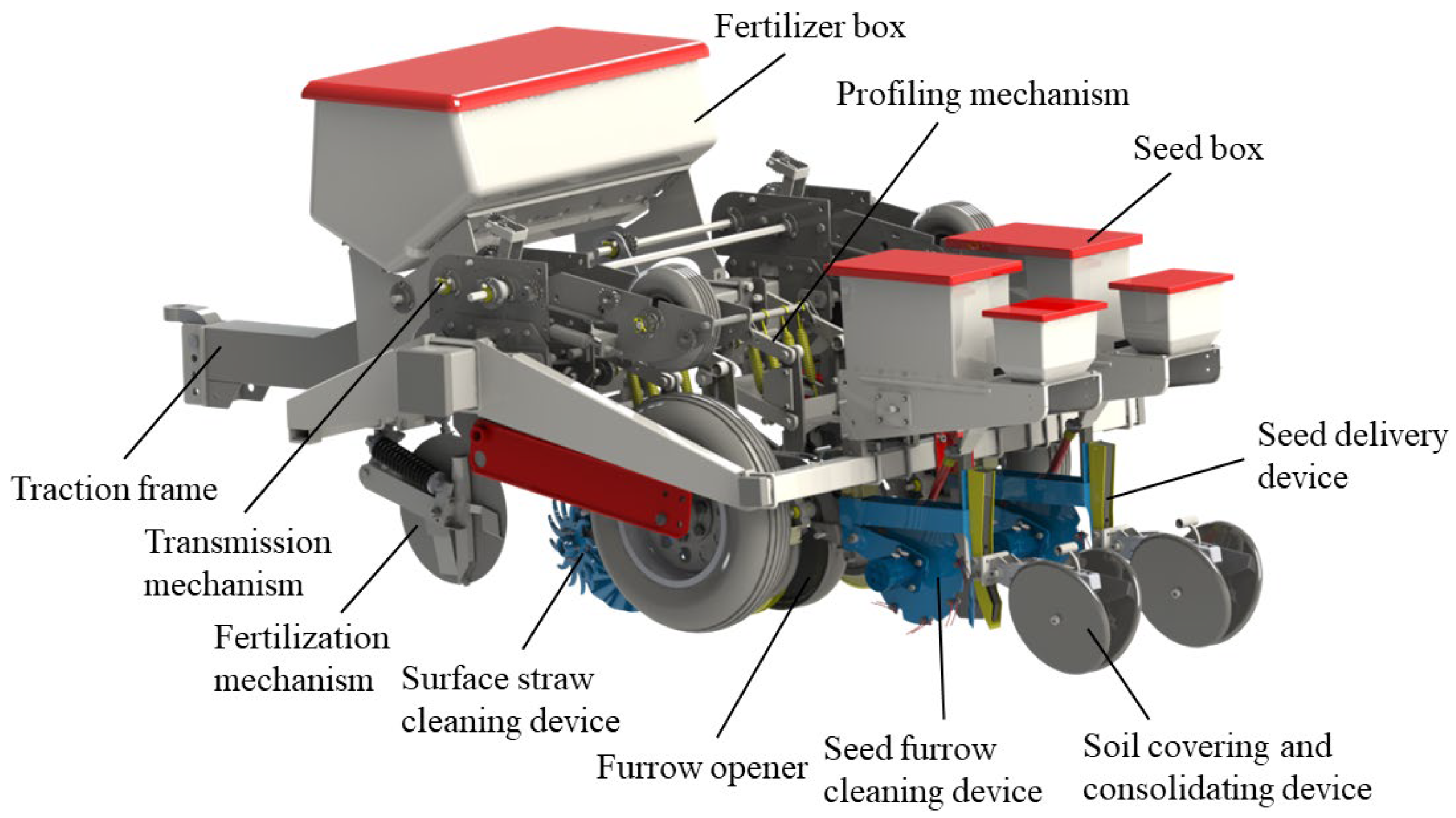
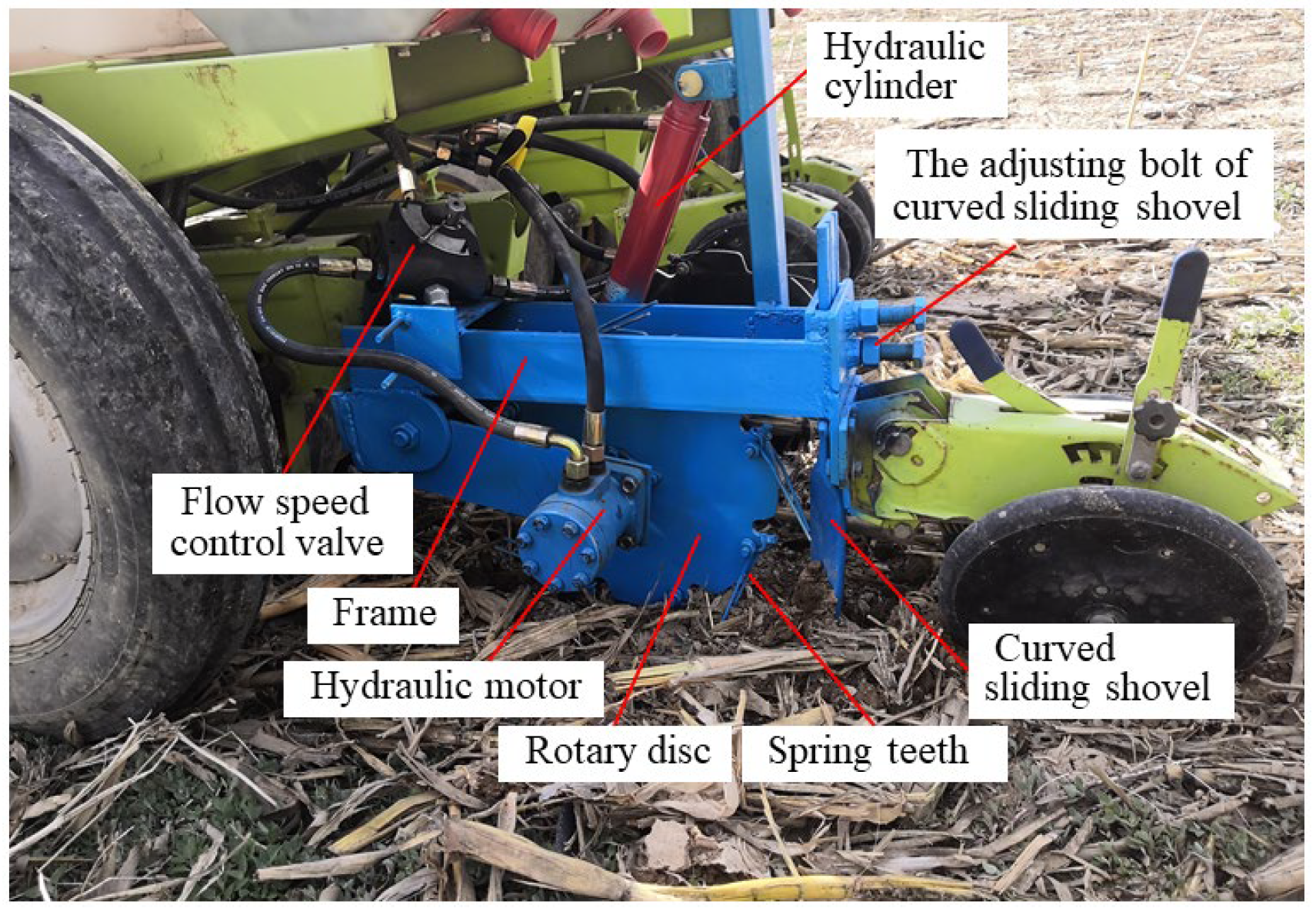
2.1.2. Structure and Working Principle of Maize No-Till Seeder
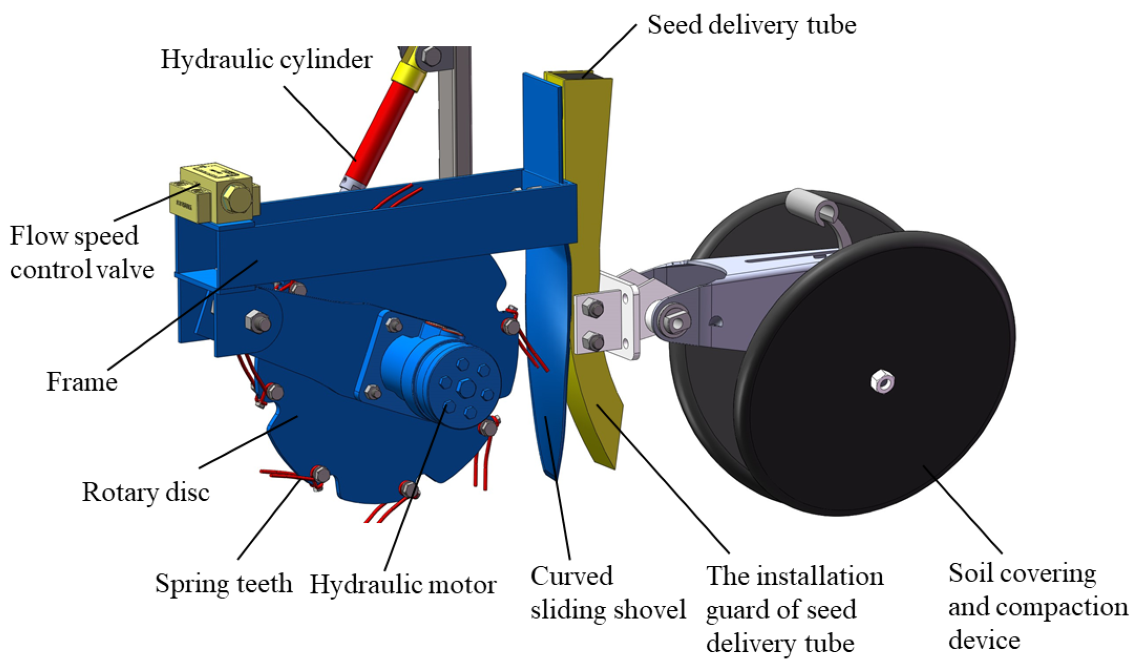
2.2. Parameter Design of the Seed Furrow Clearing Device
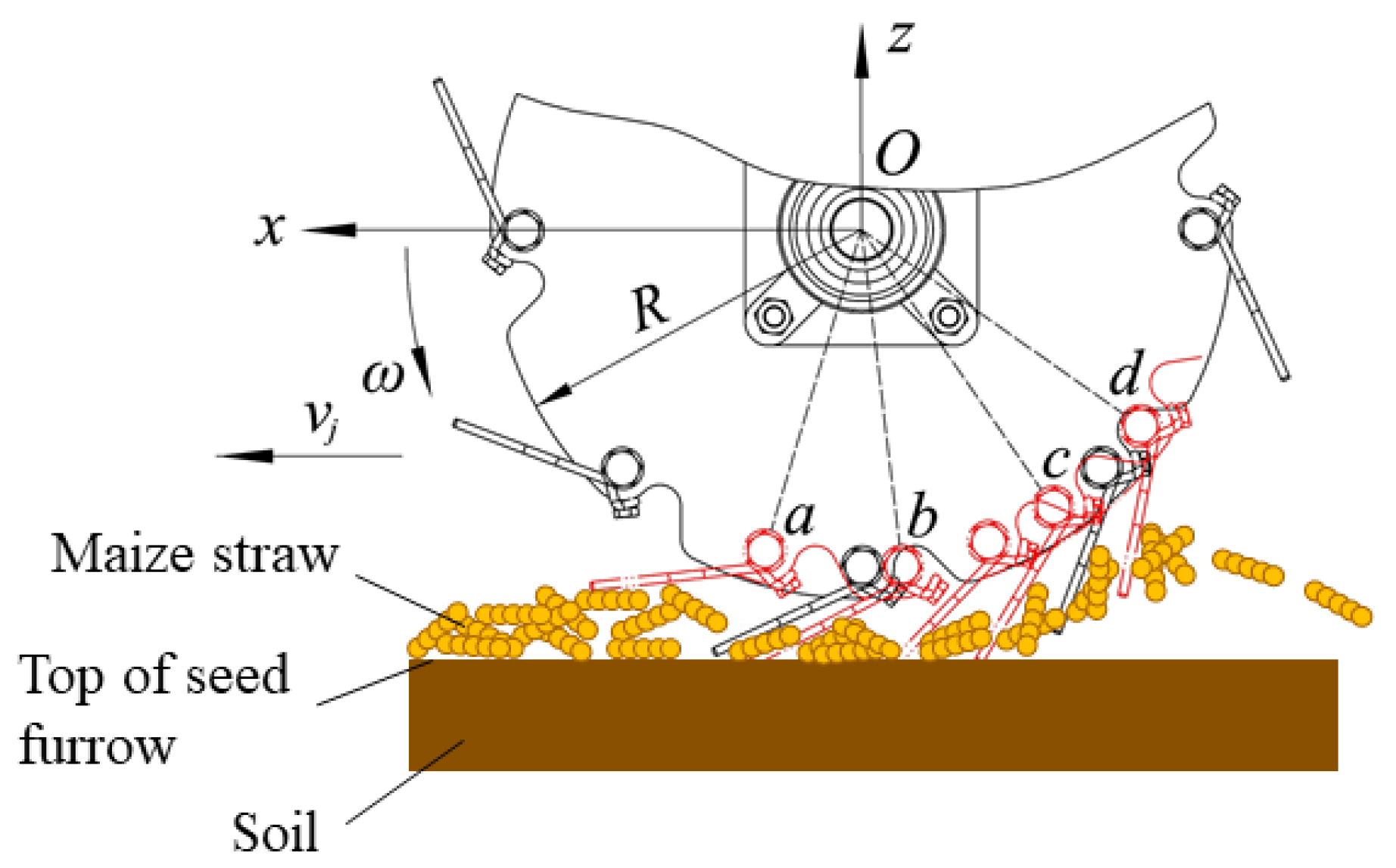
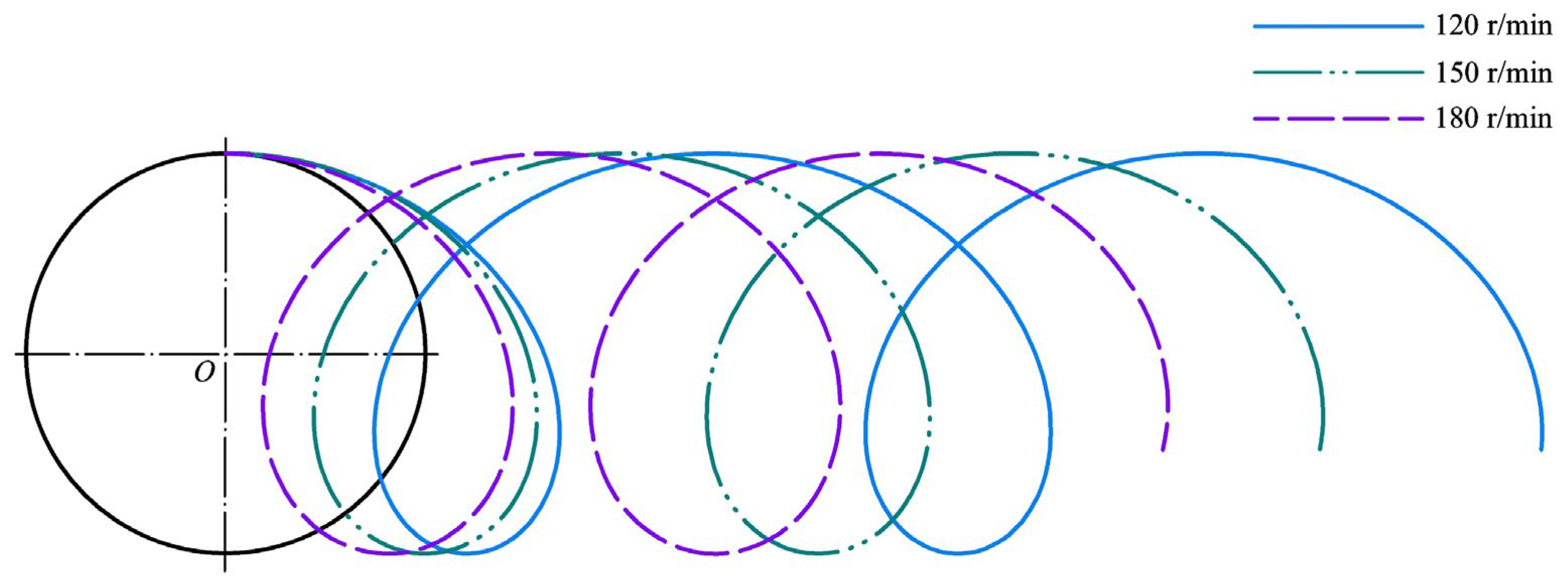
2.2.1. Throwing Mechanism
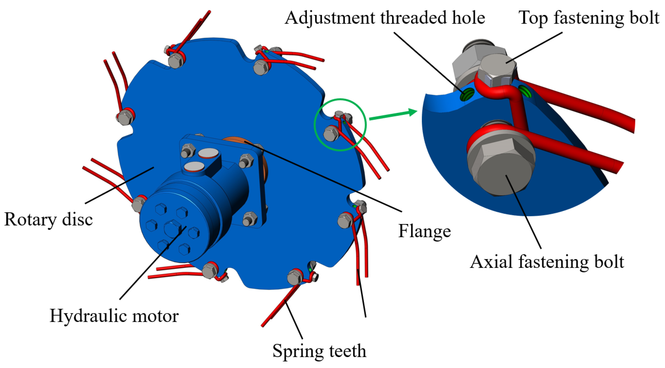
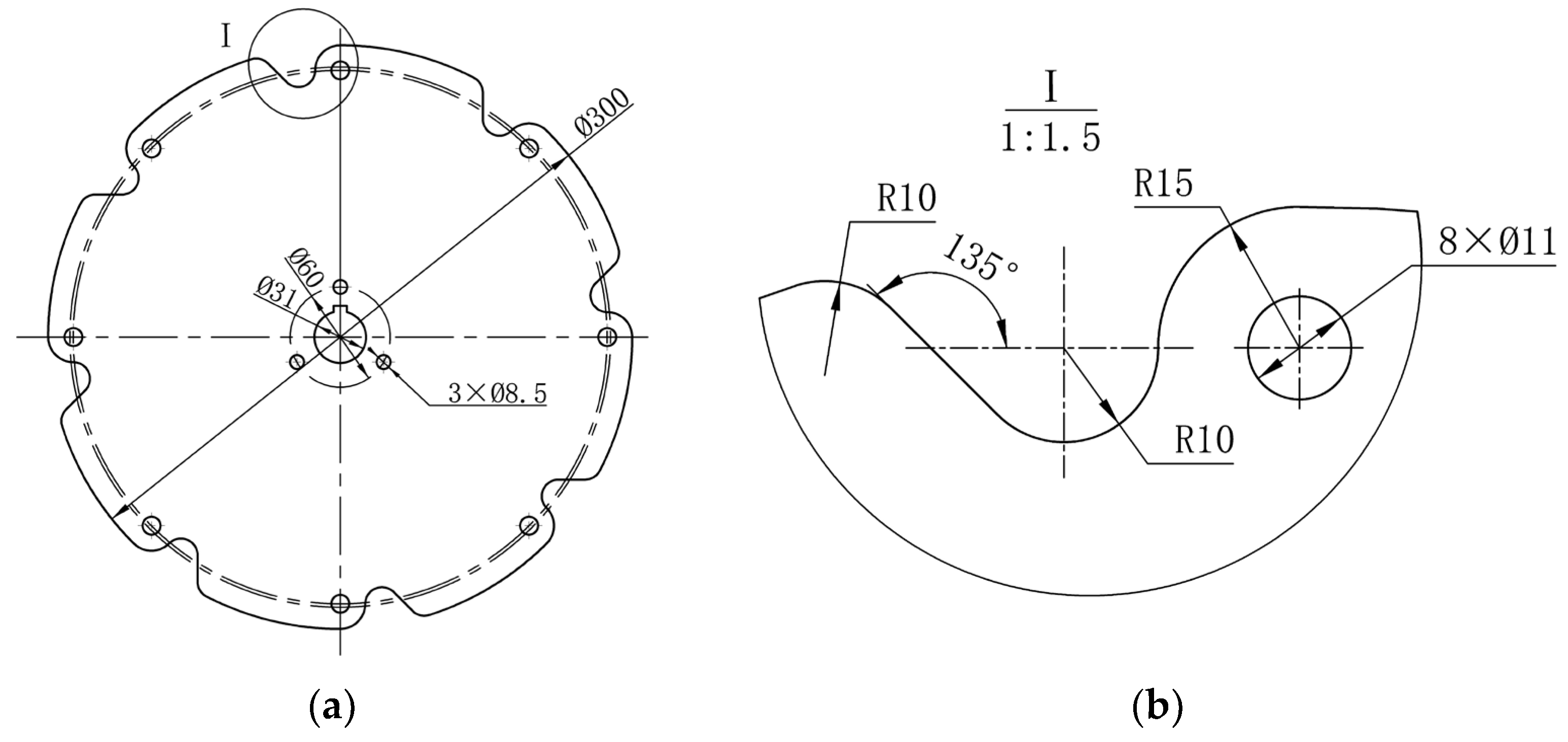
2.2.2. Rotary Disc
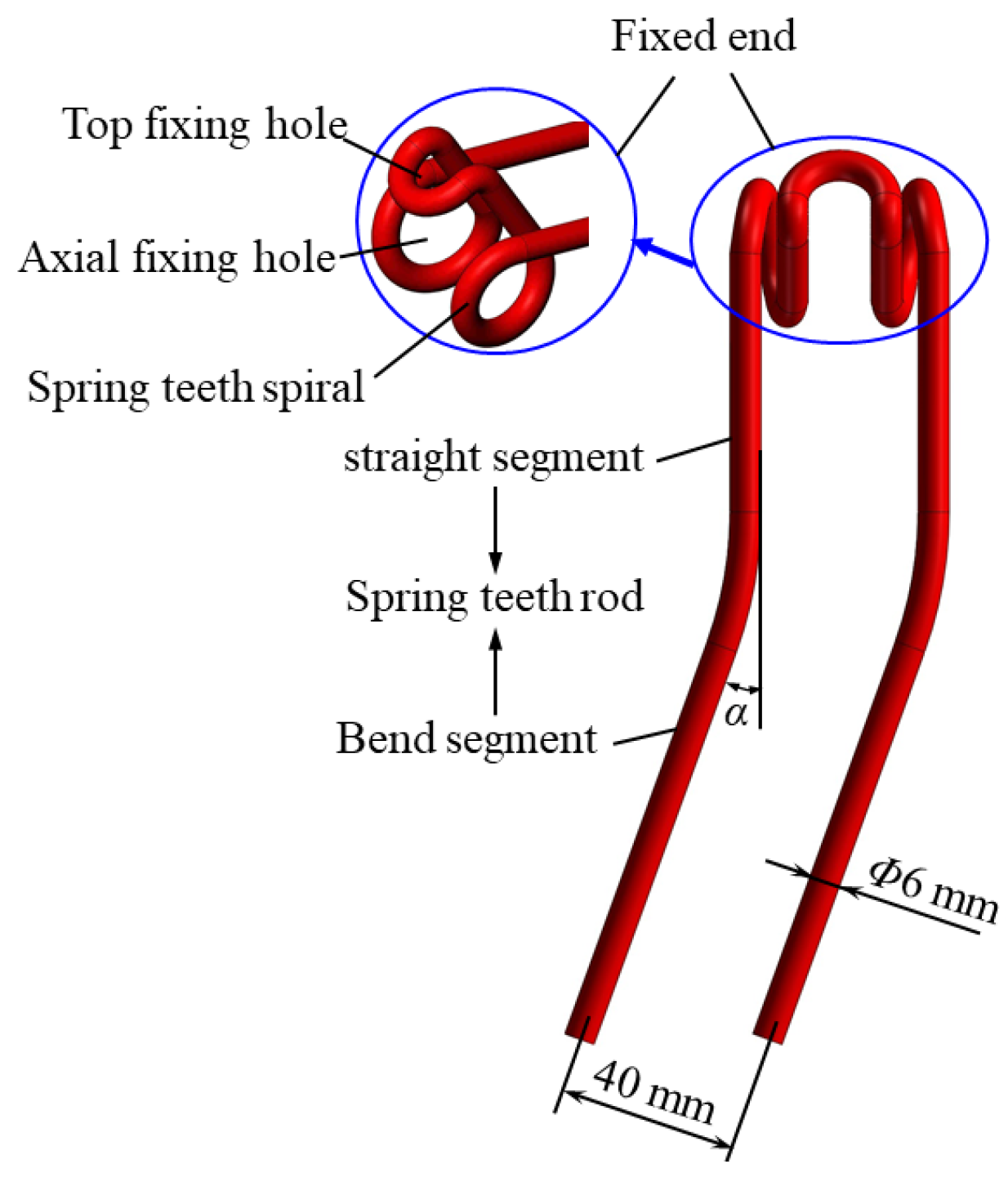
2.2.3. Spring Teeth
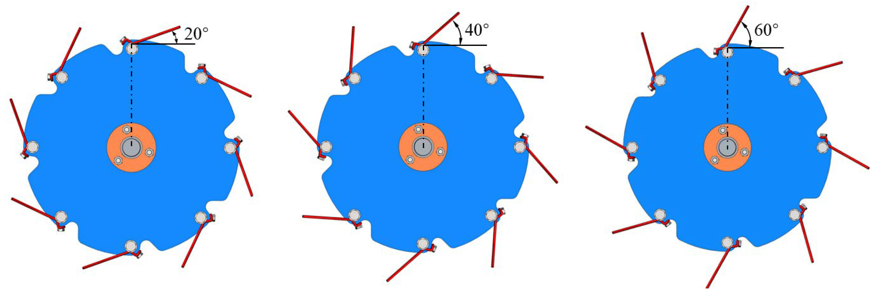
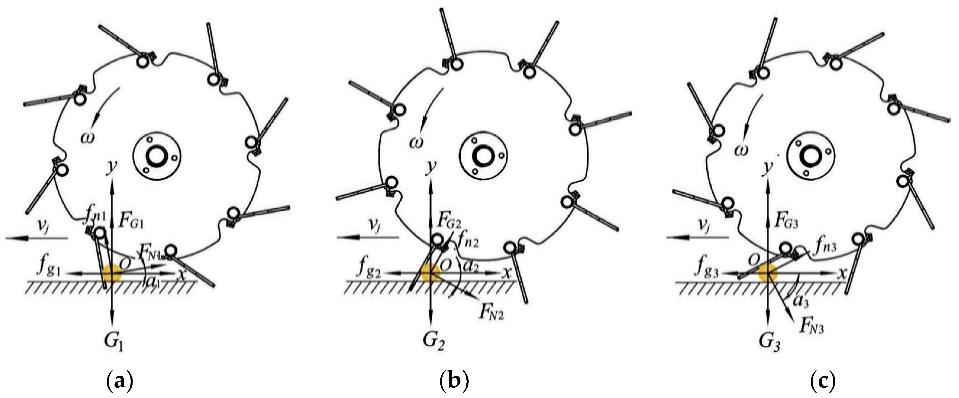
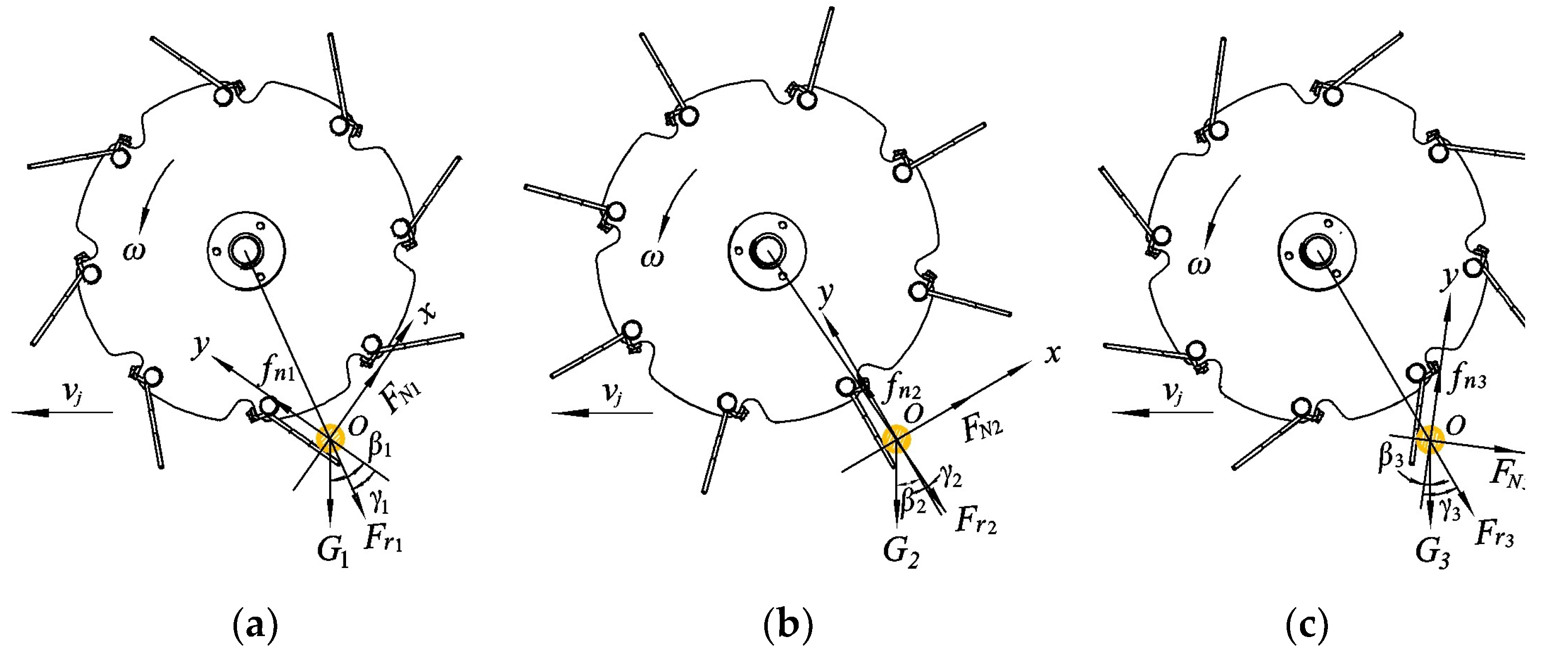
2.2.4. Installation Direction of Spring Teeth
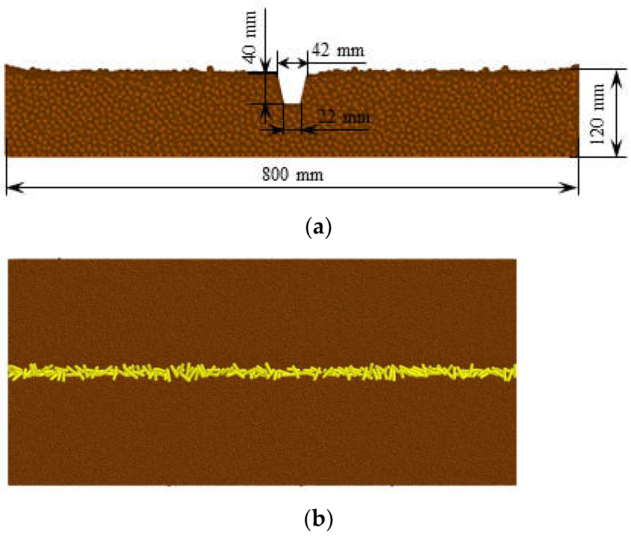
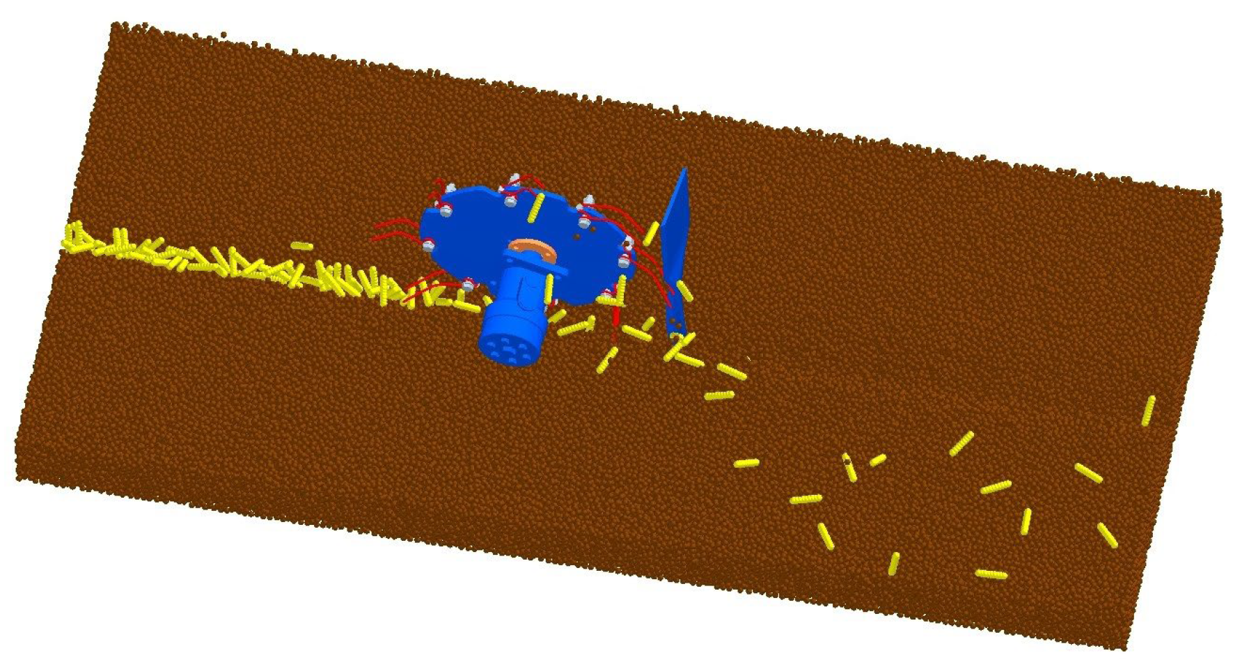
2.3. DEM Simulation
2.3.1. Model Materials
2.3.2. Test Design and Index Measurement
2.3.3. Data Collection and Processing
- The straw clearing rate (SCR)
- 2.
- Soil disturbance quality in seed furrow
2.4. Field Experiment
3. Results and Discussion
3.1. DEM Simulation Analysis
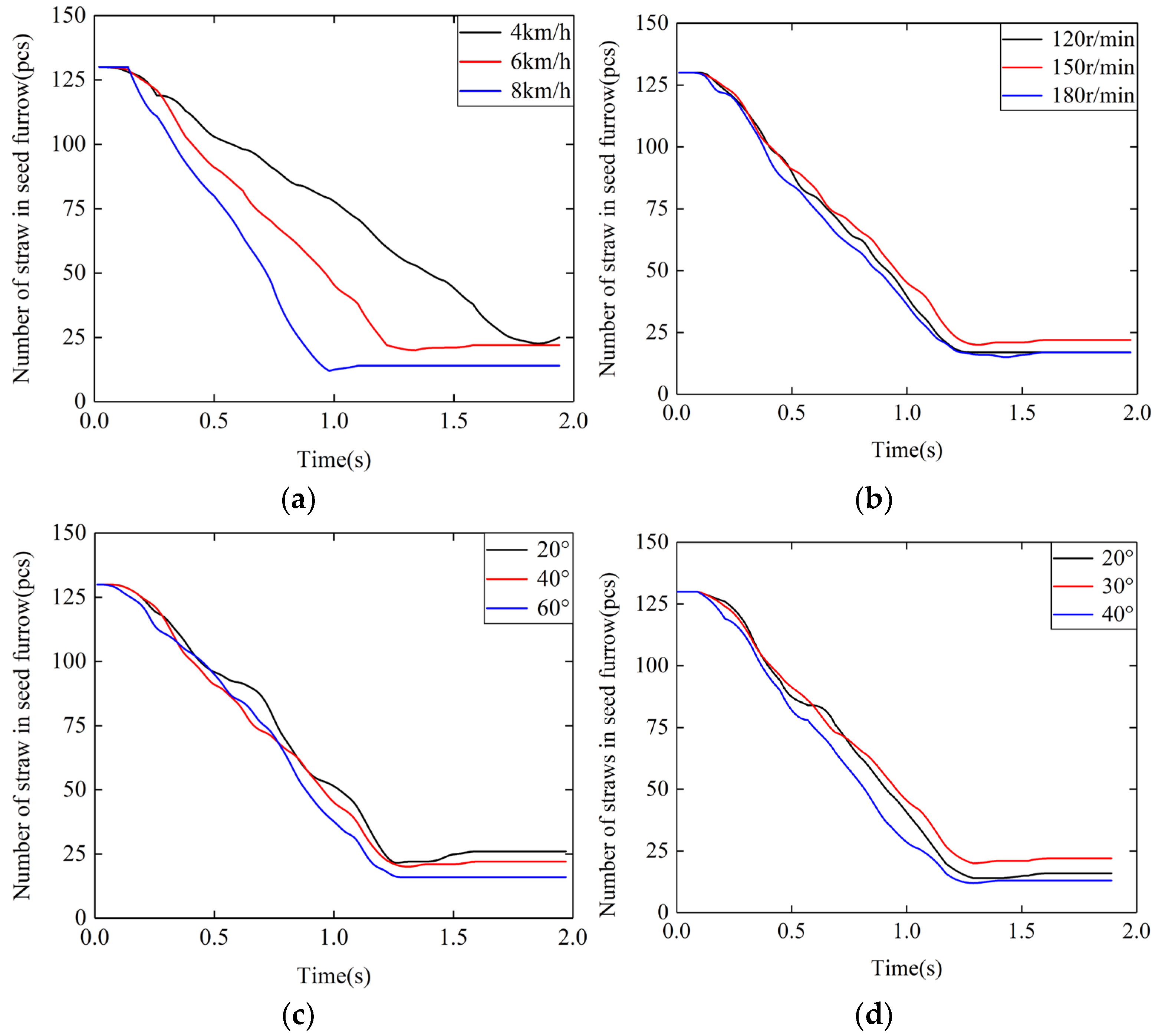
3.1.1. Seed Furrow Clearing
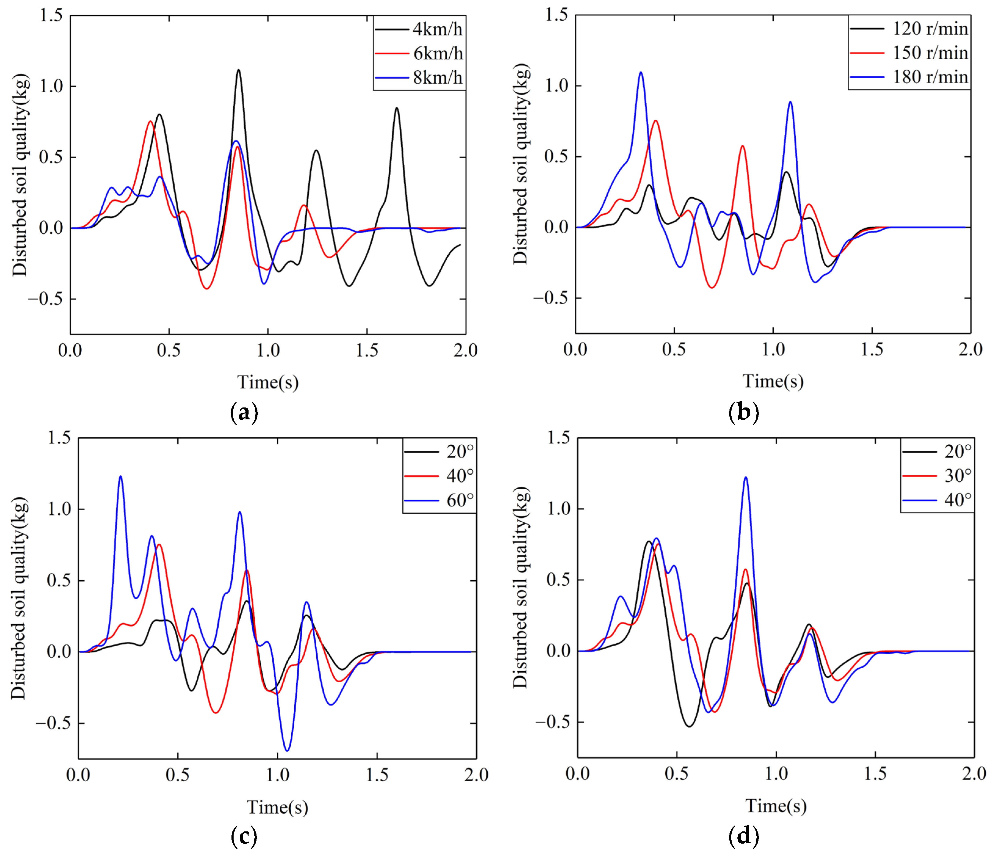
3.1.2. Seed Furrow Soil Disturbance
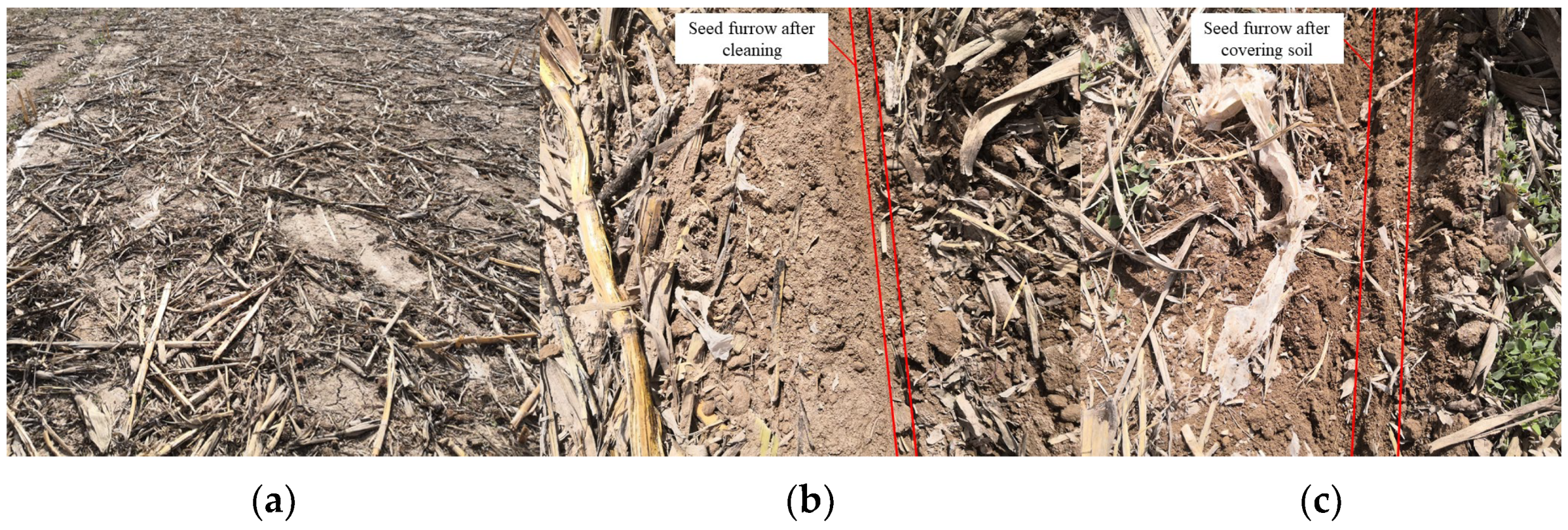
3.2. Field Experiment Analysis
4. Conclusions
- (1)
- A seed furrow clearing device for no-till maize seeding was proposed, which used rotating spring teeth and curved sliding shovel to clear the straw to the outside. The seed furrow was cleared, followed by seeding, covering and consolidating soil.
- (2)
- The installation directions of the spring teeth on the rotary disc include forward inclination, radial and backward inclination. The force on the straw at the moment of starting to touch and throwing the straw was analyzed theoretically, and the backward inclination of the spring teeth was determined. In the appropriate backward inclination angle, the stirring of the spring teeth would not affect, and the straw would fall off the spring teeth.
- (3)
- The straw clearing rate and soil disturbance were analyzed by using the DEM method. The results indicated that increases in the forwarding speed, rotating speed, installation inclination angle and bending angle, the straw clearing rate increased, generally. With the increase of the forwarding speed, the straw clearing effect was improved, and the soil disturbance was small, the forwarding speed was determined as 8 km/h. With the increase of the rotating speed, the soil disturbance increased, to obtain better clearing effect, the rotating speed was determined as 180 r/min. With the increase of installation inclination angle, the soil disturbance increased, according to the indicators of straw clearing and soil disturbance, the installation inclination angle was selected as the median value 40°. The change of bending angle had little effect on soil disturbance, according to straw clearing, the bending angle was determined as 30°.
- (4)
- The field experiment results showed that when the rotating speed was 180 r/min, installation inclination angle of spring teeth was 40°, and bending angle was 30°, the SCR was 82.26%.
Author Contributions
Funding
Institutional Review Board Statement
Data Availability Statement
Acknowledgments
Conflicts of Interest
References
- Chabert, A.; Sarthou, J.P. Conservation agriculture as a promising trade-off between conventional and organic agriculture in bundling ecosystem services. Agric. Ecosyst. Environ. 2020, 292, 106815. [Google Scholar] [CrossRef]
- He, J.; Li, H.; Chen, H.; Lu, C.; Wang, Q. Research progress of conservation tillage technology and machine. Trans. Chin. Soc. Agric. Mach. 2018, 49, 1–19. [Google Scholar]
- Liu, J.; Li, J.; Zhou, Y.; Fu, Q.; Zhang, L.; Liu, L. Effects of straw mulching and tillage on soil water characteristics. Trans. Chin. Soc. Agric. Mach. 2019, 50, 333–339. [Google Scholar]
- Celik, A.; Altikat, S.; Way, T.R. Strip tillage width effects on sunflower seed emergence and yield. Soil Tillage Res. 2013, 131, 20–27. [Google Scholar] [CrossRef]
- Nyakudya, I.W.; Stroosnijder, L. Conservation tillage of rainfed maize in semi-arid Zimbabwe: A review. Soil Tillage Res. 2015, 145, 184–197. [Google Scholar] [CrossRef]
- Zeng, Z.; Chen, Y. Performance evaluation of fluted coulters and rippled discs for vertical tillage. Soil Tillage Res. 2018, 183, 93–99. [Google Scholar] [CrossRef]
- Liu, Z.; Liu, L.; Yang, X.; Zhao, Z.; Liu, X. Design and experiment of no-till precision planter for corn. Trans. Chin. Soc. Agric. Eng. 2016, 32, 1–6. [Google Scholar]
- Wang, Q.; Cao, X.; Wang, C.; Li, H.; He, J.; Lu, C. Research progress of no/minimum tillage corn seeding technology and machine in northeast black land of China. Trans. Chin. Soc. Agric. Mach. 2021, 52, 1–15. [Google Scholar]
- KUHN Krause Gladiator. Available online: https://www.kuhn-usa.com/crop/tillage-tools/strip-till (accessed on 8 September 2022).
- Olaf, E. Cropping systems and crop residue management in the Trans-Gangetic Plains: Issues and challenges for conservation agriculture from village surveys. Agric. Syst. 2011, 104, 54–62. [Google Scholar]
- Siemens, M.C.; Wilkins, D.E.; Correa, R.F. Development and evaluation of a residue management wheel for hoe-type no-till drills. Trans. ASAE 2003, 47, 397–404. [Google Scholar] [CrossRef]
- Ahmad, F.; Qiu, B.; Ding, Q.; Ding, W.; Khan, Z.M.; Shoaib, M.; Chandio, F.A.; Rehim, A.; Khaliq, A. Discrete element method simulation of disc type furrow openers in paddy soil. Int. J. Agric. Biol. Eng. 2020, 13, 103–110. [Google Scholar] [CrossRef]
- Hou, S.; Chen, H.; Zou, Z.; Wei, Z.; Zhang, Y. Design and test of lateral stubble cleaning blade for corn stubble field. Trans. Chin. Soc. Agric. Eng. 2020, 36, 59–69. [Google Scholar]
- DALE DRILLS Eco L. Available online: http://www.daledrills.com/drill-range/eco–drill (accessed on 8 September 2022).
- John Deere 1705 Twin Row Planter. Available online: https://www.deere.com/en/planting-equipment/1705-twin-row-planter/# (accessed on 8 September 2022).
- Zhang, X.; Li, H.; Du, R.; Ma, S.; He, J.; Wang, Q.; Chen, W.; Zheng, Z.; Zhang, Z. Effects of key design parameters of tine furrow opener on soil seedbed properties. Int. J. Agric. Biol. Eng. 2016, 9, 67–80. [Google Scholar]
- Yuan, P.; Li, H.; Jiang, G.; He, J.; Lu, C.; Huang, S. Design and experiment of straw cleaning device for wide narrow maize no-tillage sowing strip in drip irrigation area. Trans. Chin. Soc. Agric. Mach. 2021, 52, 43–52. [Google Scholar]
- AGCO Sunflower STRIP-TILL TOOLS. Available online: https://www.sunflowermfg.com/tillage-equipment/strip-till (accessed on 8 September 2022).
- Sharipov, G.M.; Paraforos, D.S.; Pulatov, A.S.; Griepentrog, H.W. Dynamic performance of a no-till seeding assembly. Biosyst. Eng. 2017, 158, 75–94. [Google Scholar] [CrossRef]
- Brandelero, E.M.; Araújo, A.G.D.; Ralisch, R. Coverage mobilization by different no-tillage in-line handling mechanisms. Eng. Agríc. 2015, 35, 89–97. [Google Scholar] [CrossRef] [Green Version]
- Vaitauskienė, K.; Šarauskis, E.; Romaneckas, K.; Jasinskas, A. Design, development and field evaluation of row-cleaners for strip tillage in conservation farming. Soil Tillage Res. 2017, 174, 139–146. [Google Scholar] [CrossRef]
- Boss Engineering Strip till Machines [EB/OL]. Available online: https://bossagriculture.com.au/home/strip-till-machines (accessed on 19 October 2022).
- Silva, P.R.A.; Benez, S.H.; Jasper, S.P.; Seki, A.S.; Masiero, F.C.; Riquetti, N.B. Seedrill: Mechanism of culting straw and applied vertical loads. Rev. Bras. Eng. Agrícola Ambient. 2021, 16, 1367–1373. [Google Scholar] [CrossRef]
- Wang, Q.; Jia, H.; Zhu, L.; Li, M.; Zhao, J. Design and experiment of star-toothed concave disk row cleaners for no-till planter. Trans. Chin. Soc. Agric. Mach. 2019, 50, 68–77. [Google Scholar]
- Nejadi, J.; Raoufat, M.H. Field performance of a pneumatic row crop planter equipped with active toothed coulter for direct planting of corn in wheat residue. Span. J. Agric. Res. 2013, 11, 327–334. [Google Scholar] [CrossRef] [Green Version]
- Matin, M.A.; Fielke, J.M.; Desbiolles, J.M.A. Torque and energy characteristics for strip-tillage cultivation when cutting furrows using three designs of rotary blade. Biosyst. Eng. 2015, 129, 329–340. [Google Scholar] [CrossRef]
- Li, Y.; Lu, C.; Li, H.; He, J.; Wang, Q.; Huang, S.; Gao, Z.; Yuan, P.; Wei, X.; Zhan, H. Design and experiment of spiral discharge anti-blocking and row-sorting device of wheat no-till planter. Agriculture 2022, 12, 468. [Google Scholar] [CrossRef]
- Zhu, H.; Qian, C.; Bai, L.; Zhao, H.; Ma, S.; Zhang, X.; Li, H. Design and experiments of active anti-blocking device with forward-reverse rotation. Trans. Chin. Soc. Agric. Eng. 2022, 38, 1–11. [Google Scholar]
- Wang, W.; Zhu, C.; Chen, L.; Li, Z.; Huang, X.; Li, J. Design and experiment of active straw-removing anti-blocking device for maize no-tillage planter. Trans. Chin. Soc. Agric. Eng. 2017, 33, 10–17. [Google Scholar]
- Cao, X.; Wang, Q.; Li, H.; He, J.; Lu, C.; Yu, C. Design and experiment of active rotating collective straw-cleaner. Trans. Chin. Soc. Agric. Eng. 2021, 37, 26–34. [Google Scholar]
- Yu, C.; Wang, Q.; Li, H.; He, J.; Lu, C.; Liu, H. Design and Experiment of Spiral-split Sowing Strip Cleaning Device. Trans. Chin. Soc. Agric. Mach. 2020, 51, 212–219. [Google Scholar]
- Yuan, P.; Li, H.; Lu, C.; Wang, Q.; He, J.; Huang, S.; Cui, D. Design and experiment of seed furrow cleaning device based on throwing and sliding for no-till maize seeding. Int. J. Agric. Biol. Eng. 2022, 15, 95–102. [Google Scholar] [CrossRef]


| Object | Poisson’s Ratio | Shear Modulus (MPa) | Density (kg/m3) |
|---|---|---|---|
| soil particle | 0.38 | 1.0 × 10⁶ | 1850 |
| steel | 0.3 | 7.0 × 10¹⁰ | 7800 |
| straw | 0.4 | 7.0 × 10⁶ | 180 |
| Object | Soil-Straw | Soil-Soil | Straw-Straw | Steel-Soil | Steel-Straw |
|---|---|---|---|---|---|
| Coefficient of restitution | 0.5 | 0.25 | 0.3 | 0.28 | 0.3 |
| Coefficient of static friction | 0.3 | 0.4 | 0.3 | 0.5 | 0.3 |
| Coefficient of rolling friction | 0.05 | 0.25 | 0.01 | 0.04 | 0.01 |
| Number | Factor | Variable Values | Conditions |
|---|---|---|---|
| 1–3 | Forwarding speed vj/(km·h−1) | 4, 6, 8 | n = 150 r·min−1 θ = 40° α = 30° |
| 4–6 | Rotating speed n/(r·min−1) | 120, 150, 180 | vj = 6 km·h−1 θ = 40° α = 30° |
| 7–9 | Inclination angle of spring teeth θ/° | 20, 40, 60 | vj = 6 km·h−1 n = 150 r·min−1 α = 30° |
| 10–12 | Bending angle of spring teeth α/° | 20, 30, 40 | vj = 6 km·h−1 n = 150 r·min−1 θ = 40° |
| No. | SCR/% |
|---|---|
| 1 | 73.42 |
| 2 | 85.10 |
| 3 | 92.13 |
| 4 | 74.91 |
| 5 | 82.57 |
| 6 | 89.82 |
| 7 | 71.28 |
| 8 | 80.96 |
| 9 | 90.14 |
| Average | 82.26 |
Publisher’s Note: MDPI stays neutral with regard to jurisdictional claims in published maps and institutional affiliations. |
© 2022 by the authors. Licensee MDPI, Basel, Switzerland. This article is an open access article distributed under the terms and conditions of the Creative Commons Attribution (CC BY) license (https://creativecommons.org/licenses/by/4.0/).
Share and Cite
Yuan, P.; Li, H.; Huang, S.; Jiang, S.; Xu, J.; Lin, H.; Li, R. Parameter Optimization and Experiment of a Seed Furrow Cleaning Device for No-Till Maize Seeding. Agriculture 2022, 12, 1901. https://doi.org/10.3390/agriculture12111901
Yuan P, Li H, Huang S, Jiang S, Xu J, Lin H, Li R. Parameter Optimization and Experiment of a Seed Furrow Cleaning Device for No-Till Maize Seeding. Agriculture. 2022; 12(11):1901. https://doi.org/10.3390/agriculture12111901
Chicago/Turabian StyleYuan, Panpan, Hongwen Li, Shenghai Huang, Shan Jiang, Jing Xu, Han Lin, and Rongrong Li. 2022. "Parameter Optimization and Experiment of a Seed Furrow Cleaning Device for No-Till Maize Seeding" Agriculture 12, no. 11: 1901. https://doi.org/10.3390/agriculture12111901