Article

Design and Operating Parameters Optimization of the Hook-and-Tooth Chain Rail Type Residual Film Picking Device

1
College of Mechanical and Electrical Engineering, Xinjiang Agricultural University, Urumqi 830052, China
2
Mechanical Equipment Research Institute, Xinjiang Academy of Land Reclamation Sciences, Shihezi 832000, China
3
Xinjiang Key Laboratory of Intelligent Agricultural Equipment, Urumqi 830052, China
4
College of Mechanical and Electrical Engineering, Shihezi University, Shihezi 832000, China
5
Institute of Agricultural Mechanization, Xinjiang Academy of Agricultural Sciences, Urumqi 830091, China
*
Author to whom correspondence should be addressed.
Agriculture 2022, 12(10), 1717; https://doi.org/10.3390/agriculture12101717
Submission received: 26 September 2022 / Revised: 12 October 2022 / Accepted: 15 October 2022 / Published: 18 October 2022
(This article belongs to the Special Issue Design and Application of Agricultural Equipment in Tillage System)

Abstract

:
We attempt to solve the current problems of high impurity content and the poor reliability of chain harrow type residual film recovery machines when picking up residual film. This study makes a device for picking up residual film with a hook-and-tooth chain rail. First, we conducted an analysis of the trajectory of the tip movement of the hooked teeth in the designed picking device, with the condition that the residual mulch does not miss the picking, and the force conditions of the residual mulch in the conveying process and the collection process are presented. Secondly, to determine the optimal working parameters of the picking device, a three-factor, three-level response surface optimization test was conducted with the machine forward speed, hook tooth entry depth, and chain harrow input speed as the test factors and the residual film picking rate and the impurity rate of residual film as the test indexes. In addition, a response surface regression model was developed to analyze the effects of the selected factors on the picking device. When the forward speed of the machine was 1.62 m/s, the hook tooth entry depth was 38.51 mm, and the input speed of the chain harrow was 241.42 rpm, the pickup rate and the impurity rate of the residual film were 88.27% and 9.96%, respectively. Finally, the simulation test was carried out under optimal working conditions, with the maximum force of the hook teeth being 60.7 N, the maximum deformation being 31.42 mm, and the maximum stress being 215.33 Mpa. This study can be used as a guide to further improve the design of the residual film recovery machine.

1. Introduction

Mulching technology has been widely used in the production of a variety of crops since its introduction to China in the 1970s due to its ability to increase temperature and conserve moisture, save water and drought, and improve quality and yield [1,2]. For more than 40 years, Xinjiang has used mulch cultivation technology in cotton fields as an important commercial cotton production base in China, which has greatly contributed to the development of the local agricultural economy [3]. In addition, as the amount of film applied and years of use increase, the “white pollution” caused by large amounts of residual film not only seriously affects agricultural production, but also poses a great threat to the safety and health of the agricultural environment. Residual film on farmland has become one of the most important elements that affects the agricultural environment, destroys soil structure, reduces the quality of cultivated land, affects the growth of crops, and causes crop yield reduction, which poses a huge threat for the sustainable development of agriculture [4].
Developed countries use film with a thickness of 0.02 mm or greater, covering a shorter period of time while maintaining greater strength and not easily breaking when recovered, which is generally recovered in the form of rolls, with the main working parts being the starting shovel and rolls. Lavor invented a film recycling machine that removed soil from the film with a brush before rolling it up for collection [5]. R.L. Parish created a device that controls the flow of the hydraulic motor in order to regulate its speed and match the speed of the mulcher roll line to the speed of the recycler [6]. The film recycler was designed by ROCCA to transport the film to the film rollers at the back of the machine using a chain conveyor that lifts the film and separates it from the soil on its surface [7].
To address the problem of film pollution, related research institutions in China developed over a hundred different types of film recovery machines, which can be classified as telescopic roller type, shovel type, wheel-tooth type, chain rake type, and other major film picking devices based on different film collection principles [8,9,10]. Among these are the chain rake collection principles, which include high-speed film transfer to the collection device via the bullet teeth, chain rake damage that is easy to replace, a strong ability to remove soil and row miscellaneous, and a higher residual film recovery rate [11]. Guo Wensong created the 4CML-1000 chain harrow type residual film recovery machine, which can perform film collection, transfer, and unloading operations in real time. The residual film recovery rate is higher, but the forward speed of the machine is only 2.542 km/h, resulting in low operational efficiency. [12]. Xie Jianhua designed a surface residual film recovery machine with guided chain rake tines to solve the problem of a chain tine type film picking device for film removal that requires bending of the conveyor chain and uses a rotating film removal device with guided rake tines to enhance the film removal effect [13]. Moreover, the machine is only designed for 2.05 m cotton fields, and differences in planting conditions and farming operations affect edge film compaction during harvesting, making the effect of edge film lifting uncertain.
Based on the dwarf dense planting pattern of Xinjiang machine harvested cotton and the characteristics of an existing chain harrow type residual film recovery machine, a hook-and-tooth chain rail type residual film picking device was designed in this paper based on the structure and characteristics of existing recovery devices. The reasonable structure and operation parameters of the machine were determined through theoretical analysis and field tests, and the influence of different factors on the effect of residual film recovery was explored. As a result, a better combination of parameters was obtained to provide reference for further optimization of the design of the residual film recovery machine.

2. Materials and Methods

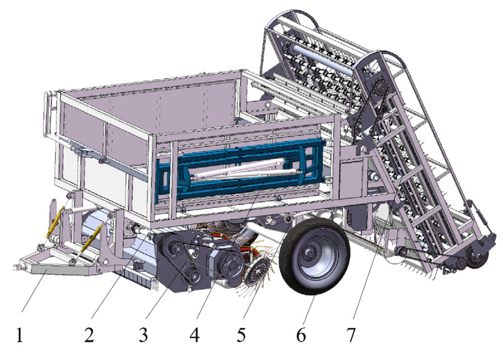
2.1. Structure and Working Principle of Residual Film Recycling Machine

The residual film recycling machine is mainly composed of a hook-up device, a power transmission system, a straw crushing device, a hook-and-tooth chain rail type residual film picking device, and a film storage and launching device, as shown in Figure 1.
When the machine is activated, the tractor’s rear output shaft is connected to the machine drive system and power is transmitted to the straw shredding device. The shredding knife rotates at high speed to shred the straw, and the shredded straw is thrown to the winch in a centrifugal action. The rotating winch throws the straw to the ground. In the film picking device, the hook and tine assembly’s curved side conveyor chain drives the passive shaft under the chain rake frame for repeated movement. Picked residual film is conveyed upward to the de-filming shaft, which scrapes it into the film collection box. When unloading film, a hydraulic control system opens the side door and drives the fork arm to compact and push out the film.

2.1.1. The Main Components and Working Principle of The Picking Device

The executive component of the film pick-up operation is the hook and tooth chain rail type residual film picking device, which is made up of a chain rake frame, an articulated short shaft, a flap for discharging debris and preventing mulch from sucking back parts, a de-filming shaft, a curved edge conveyor chain, a guide beam, a hook and tooth assembly, a chain rake upper shaft assembly, and a lower shaft assembly. The guide beam is attached to both sides of the chain rake frame’s inner edge, the curved side conveyor chain is attached to the upper part of the guide beam, and the articulated short shaft is symmetrically arranged on both sides of the curved edge conveyor chain and fixed on the curved edge conveyor chain bend plate using bolt sets. The articulated short shaft is inserted into the hook tooth mounting shaft from both ends, and a hook tooth assembly is arranged for every 6 links. The film removal axis is installed on the outer side of the chain rake upper shaft assembly, and the mounting plate is welded to the chain rake frame, located below the film removal axis to connect the picking device to the entire machine. Figure 2 shows the installation position of each component of the picking device. Table 1 shows the mechanism’s main operating parameters.
When the picking device operates, power is input by the machine’s rear drive shaft, and the power input sprocket rotates the upper shaft of the chain rake, while the curved side conveyor chain synchronously drives the hook tooth installation shaft and the lower shaft of the chain rake installed on it. Hook teeth in the machine travel forward into the soil to pick up film, with the installation axis running from bottom to top to transport the residual film. The impurities in the residual film are picked up by shaking off the chain drive and fall down to the two-way spiral discharge winch at the discharge flap, where the size of the opening of the discharge flap can be controlled by the adjusting screw. In the upward conveying process, the articulated short shaft supports the hook tooth assembly, the limiting bracket prevents axial flinging in the film conveying, and the guideway beams on both sides ensure the motion track. When the hook teeth transfer the residual film to the top of the film removal area, the hook teeth assembly in the chain rake frame shift slide and limit bracket together, completing the hook teeth installation axis shift flip, and changing the tooth tip direction. The film scraper on the film release shaft now rotates in the opposite direction to scrape off the residual film on the hook teeth. A serrated baffle is welded to the front end of the film shaft to prevent the scraped out residual film from being hung up again by the hook teeth, ensuring that the residual film can fall smoothly to the film storage device after scraping out.

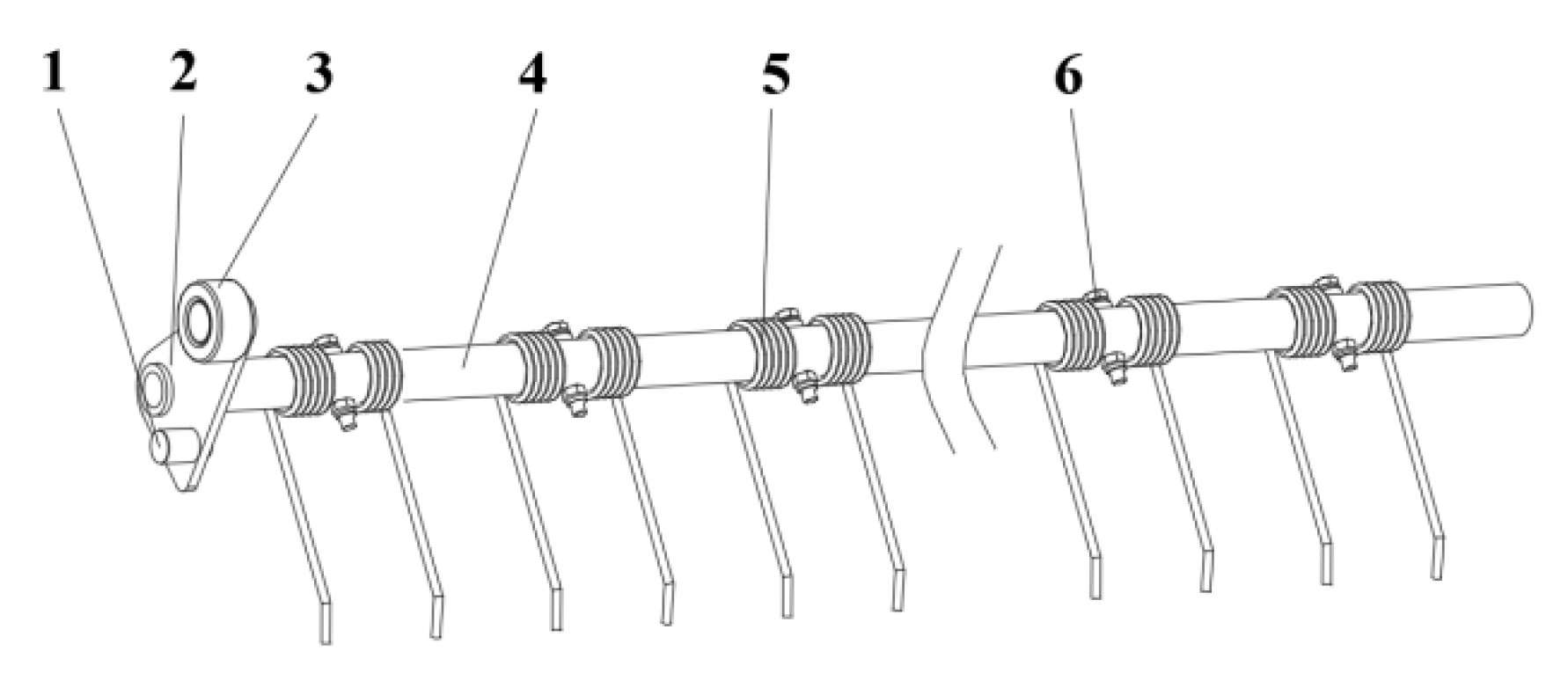
2.1.2. Hook Tooth Assembly

The hook tooth assembly is made up of a roller, a guiding side plate, a limiting short shaft, a hook tooth mounting shaft, a hook tooth, a threaded fastener, and other components. Figure 3 shows the structure.
In Figure 2, the chain rake frame structure characteristics can be seen. In picking up film teeth movement to the nearest position, direction changing chute will top up the guide side plate connected to the short axis so that the hook tooth assembly around the two ends of the hook tooth articulated short axis produce deflection, and the hook tooth assembly installed hook tooth rod and vertical direction angle becomes smaller, as in the hook tooth assembly off the film area rotation, as shown in Figure 4.
Then the effective lenght of the change of direction slide is
L a = R a c o s φ
where La is the effective length of the deflection chute, (mm); Ra is the distance from the center of the hook tooth mounting shaft to the center of the short shaft, (mm); φ is the rotation angle of the hook tooth assembly, (°).
The design hook tooth installation axis is 58 mm away from the center of the short axis, the rotation angle of the hook tooth assembly in the de-filming area is 60°, and La = 29 mm can be obtained from an equation based on the characteristics of the guiding hook tooth assembly (1). If the total number of guiding hook teeth designed to rotate in the de-filming area is greater than two, the total number of guiding hook teeth for variable rotation in the de-filming area is 2.5 groups, and the distance between two adjacent rake teeth installation axis of rotation is 190 mm, then the effective length of the directional slide is 475 mm.

2.1.3. Pick-Up Film Hook Teeth

The hook tooth is the most critical operational component, and its performance has a direct effect on picking quality [14]. The ability of the hook tooth to support and transport residual film during operation is critical to the hook tooth’s reliability. The hook tooth’s working phase is divided into above-ground and below-ground phases, with the below-ground phase being the most complicated, as it will collide violently with the soil and produce violent vibrations when it enters the soil. To improve the self-adaptive ability of picking parts, the hook teeth are made of 65 Mn spring steel, which has good flexibility and impact resistance. By taking the entire calculation, the hook tooth diameter is 8 mm, the distance between the hook tooth teeth is 100 mm, the distance between the hook tooth axis and the hook tooth bend is 170 mm, the distance between the hook tooth bend and the tooth tip is 30 mm, and the distance between the hook tooth axis and the tooth tip is 200 mm. Furthermore, the hook tooth tip is bent in the direction of rotation to reduce residual film slippage. By conducting field pre-tests, mainly considering the deformation and damage of the hook teeth into the soil after being impacted by the load and the residual film picking effect, it was found that the best picking effect could be obtained when the angle of the hook teeth tip was 130°~160°, and there was no deformation and damage of the hook teeth, which was taken as 150° in this design, as shown in Figure 5.
According to the hook tooth force as shown in Figure 5a; with the hook tooth into the soil by the soil resistance Ff after a certain twist, the angle of the twist is φ1, and in order to ensure the efficiency of the residual film pick-up, at this time the hook tooth operation should meet the conditions of
k E d 4 φ 1 3667 Dn P F f L
where k is the number of hook teeth needed to pick up the residual film per unit area; E is the modulus of elasticity (Pa); d is the diameter of the hook teeth (mm); φ1 is the angle of twist of the hook teeth into the soil (°); L is the distance from the center of rotation of the hook teeth to the tip of the teeth (mm); D is the diameter of the torsion spring (mm); n is the effective number of turns of the torsion spring; Ff is the resistance of the hook teeth into the soil (N); P is the number of hook teeth per row.
The picking device is designed to pick up the width of a film of six rows, so the condition of the number of teeth per row is
P = 2 S + 3 Z D 1 + 1
where D1 is the distance between hook teeth in the same row (mm); S is the distance between wide rows of cotton stalks (mm); Z is the distance between narrow rows of cotton stalks (mm).
According to Equations (2) and (3), if the material characteristics of the hook teeth and the middle diameter of the spring are known, whether the residual film can be transported in the clockwise direction according to the operation requirements is related to the effective number of turns of the spring and the spacing of the hook teeth. According to the previous test, the effective number of spring turns is generally 4–6 turns, and this design requires 6; according to the planting pattern of one film six rows (660 + 100 mm) in Xinjiang, the spacing of cotton stalks in wide rows S is 660 mm, the spacing of cotton stalks in narrow rows Z is 100 mm, the spacing of hook teeth in the same row D1 is 200 mm, and the number of hook teeth in each row P is 9.1 by substituting the above formula; then, 9 hook teeth or 9 half hook teeth are arranged on each of the hook tooth mounting shafts.

2.1.4. Hook Tooth Arrangement

According to the width of cotton planting in Xinjiang, the measured width after sowing is 1850~1900 mm, and the length of the hook tooth installation axis is designed to be 1875 mm. The film picking device adopts uniform film picking, and in order to avoid stress concentration in the process of film picking, the overall arrangement of hook teeth is staggered [15,16,17]. The same hook tooth installation axis is arranged with 9 hook teeth or 9 half hook teeth, and the lateral spacing of hook teeth is 200 mm; to ensure the strength of the pick-up film chain rake structure using the type 20A curved edge conveyor chain, the chain rake upper and lower axis assembly sprocket utilizing a 20A 16 tooth sprocket is employed. According to the side guide plate structure design, every 6 links required a set of guide hook teeth assemblies, and the two phase hook teeth installation axis distance was 190 mm. According to the height of the transport design, the pick-up film device to install the total number of guide rake tooth assemblies was 33 groups. The hook teeth spread arrangement is as shown in Figure 6.

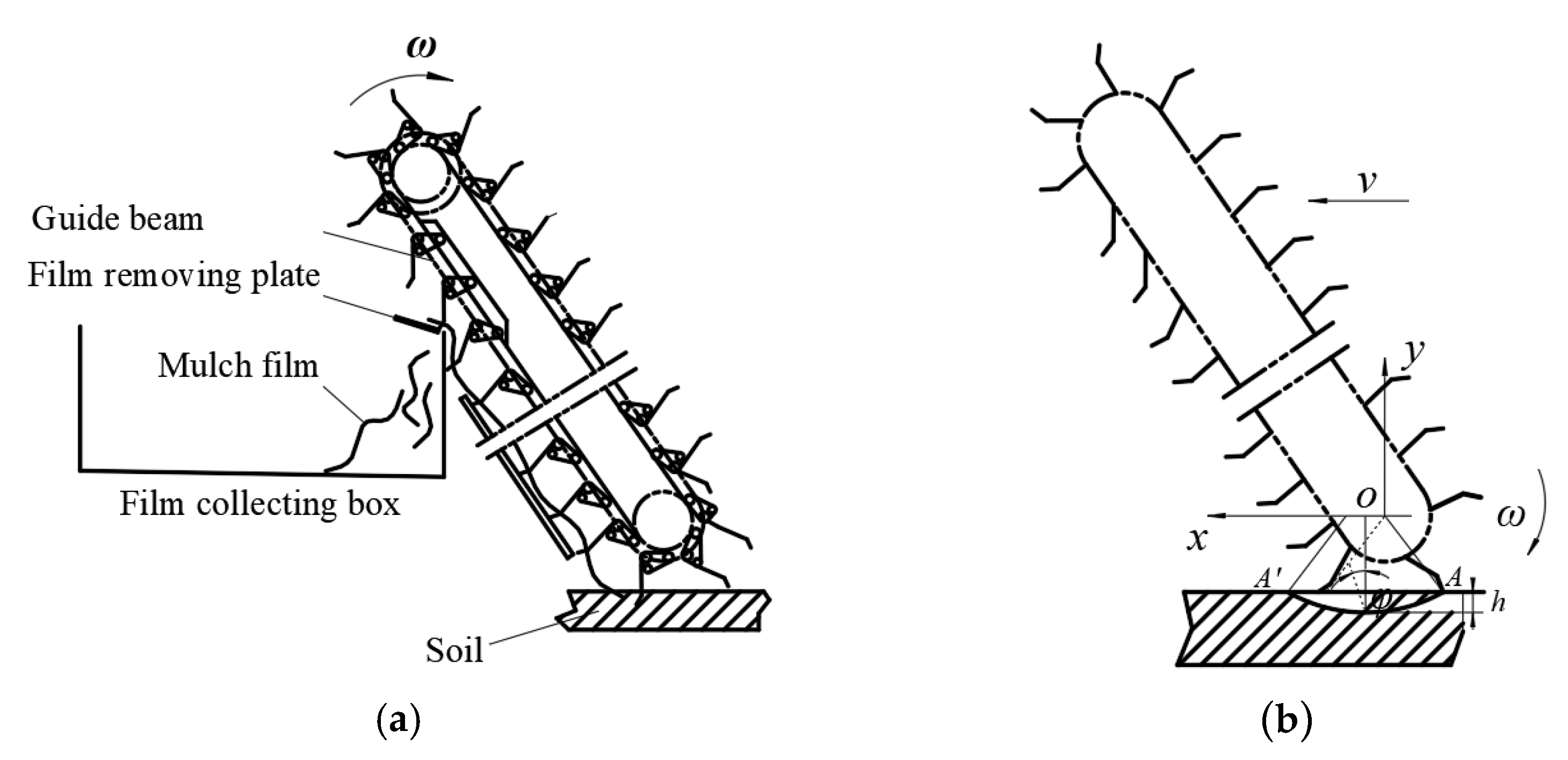
2.2. Analysis of Picking Process of Hook-Tooth Chain Rail Film Picking Device

2.2.1. Determination of Inclination Angle of Hook Teeth

The process of picking up the film is shown in Figure 7. The chain rake conveyor chain drives the hook assembly to complete the film picking, upward transportation, and reversing rotation. A guide beam is set at the chain rake frame on the right side of the tool direction, and the fixed guide side plate, roller, and limit short shaft on the right side of the hook gear assembly are matched to meet the position and attitude control of the pick-up teeth, so as to realize the limit operation of the hook gear assembly. When picking up the film, the roller is limited by the driven shaft of the chain rake to ensure the angle of the hook tooth in the soil. When conveying, the roller is constrained in the chain rake chain bending plate and the changing slideway, and the hook teeth move upward while hanging the residual mulch film without falling off. When the hook-tooth assembly moves to the peeling area, the hook-tooth assembly rotates, the straight rod of the hook-tooth changes into a vertical direction, and the tooth tip is situated downward. The lifting effect of the hook-tooth group on the residual film is weakened, and the residual film transported by the hook-tooth is unloaded under the action of the scraper, falling off smoothly to the film collecting box.
Based on the geometric relationship of the parts, using the cosine theorem, when the depth of the pickup hook reaches the maximum h, the angle φ between the LOA and the vertical direction is:
φ = arccos L s 2 + L O A 2 D 2 + E 2 L s 2 L O A
where φ is the angle between the straight line of the center of the hook assembly and the tooth tip and the vertical direction (°); Ls is the distance between rake axis and tooth tip, (mm); D is the chain rake driven shaft sprocket indexing circle diameter, (mm); E is the distance from the center of the crochet assembly to the center of the chain rake chain roller (mm); LOA is the distance from the center of chain rake driven shaft to the tip of hook tooth (mm).
The dip angle α of the hook tooth into soil obtained by the sine theorem is:
α = arcsin ( L O A h L O A )
According to the previous test combined with the existing data, it can be seen that the hook tooth needs to meet φ < 10° when it reaches the maximum depth into the soil. Ignoring the influence of the deformation of the hook tooth, the diameter of the sprocket dividing circle is designed to be D = 243.25 mm, and the distance between the center of the hook tooth assembly and the center of the chain rake chain roller is E = 40.8 mm. The angle φ between the straight line and the vertical direction of the center of the hook tooth assembly and the tooth tip is 5°, which can be substituted into the formula to obtain LOA = 359 mm. The maximum embedded depth h of the hook tooth is 60 mm, and the embedded angle α of the hook tooth is 56.4°.

2.2.2. Motion Analysis of Film-Picking Hook Teeth

As the main residual film picking part, the film picking hook tooth has an important influence on the effect of film picking operation. Therefore, the motion process of the film picking hook tooth is analyzed, and the value range of the chain rake shaft speed is determined. The curved edge conveyor chain drives the pick-up hook gear assembly to pick up the film, and the absolute motion of the pick-up hook gear is the synthesis of the forward motion of the machine and the motion of the pick-up hook gear itself. The motion trajectory of the pick-up hook gear is shown in Figure 8. Taking the rotation center O of the lower shaft of the conveyor chain rake as the coordinate origin, the forward direction of the machine is the x-axis, and the vertical direction is the y-axis to establish the rectangular coordinate system. The machine runs at a constant speed with the forward speed v, and the lower shaft of the chain rake rotates with the angular velocity. The trajectory equation of the hook tooth tip is
x = v t + L O A cos ω t y = L O A sin ω t
where LOA is the rotation radius of the hook (mm).
The velocity equation of the hook tooth tip can be obtained by taking the derivative of Formula (1) with respect to time
v x = v L O A ω sin ω t v y = L O A ω cos ω t
where vx and vy are the speed of the hook tip in the x and y directions (m/s).
As can be seen from Figure 8, the absolute motion direction of the picking film hook tooth is the tangential direction of the trajectory line. Only when vx > 0 does the picking film hook tooth have a horizontal forward speed to complete the picking film operation. At this time, the motion trajectory of the hook tooth is a trochoidal line. When v x = v L O A w sin w t = 0 :
ω L O A v = 1 s i n ω t
On account of:
v 1 = ω L O A
Substituting Formula (9) into Formula (8) has
v 1 v = 1 s i n ω t
where v1 is the linear velocity of the hook tip (m/s).
Let the ratio of the linear speed v1 of the pick-up hook tooth to the forward speed v of the machine be λ. According to the Formulae (7) and (10), it can be seen that when λ > 1, the pick-up hook tooth has a horizontal forward speed, and the pick-up chain rake rotation will pick up the residual film upward transport. If λ is too small, it is easy to make the residual film leak too much and reduce the work efficiency. If λ is too large, it is easy for the phenomenon of residual film return to appear. According to the preliminary experiment, when λ is 2.8~3.4, the test effect is better. At this time, the chain rake shaft speed can be preliminarily determined to be 210~258 r/min.
Figure 8. The motion trajectory of the pickup hook tooth.
Agriculture 12 01717 g008

2.2.3. Reliable Conditions for Residual Film Pickup

In order to realize the continuous picking up of residual film, it is necessary to analyze the conditions of the non-leakage picking up of residual film. When the machine is working, the picking film hook teeth arranged on the chain rake stand pick up the residual film in turn. The motion trajectory of the two adjacent rows of picking film hook teeth on the chain rake stand is shown in Figure 9. As the machine moves forward, the former picking film hook tooth is buried at point A at time t0, and the A′ point is unearthed at time t1. The adjacent latter picking film hook tooth is buried at point B at time t2, and the B′ point is unearthed at time t3. In this process, the distance of the lower shaft axis of the chain rake is S0. In order to realize that the residual film does not leak during the picking process, the following conditions need to be met:
S 0 S a = S b
where Sa is the distance from the previous pickup hook tooth to the lower shaft of the unearthed chain rake (mm); Sb is the distance between the adjacent rear pick-up film hook teeth and the lower shaft of the unearthed chain rake (mm).
Substituting y = L O A + h into Equation (6), we can get:
s i n ω t = L O A h L O A cos ω t = ± ( 2 L O A h 2 ) 1 2 L O A
Substituting Formula (12) into Formula (6), we can get:
x 1 = v t 0 ( 2 L O A h 2 ) 1 2
x 2 = v t 1 + ( 2 L O A h 2 ) 1 2
x 3 = v t 2 + ( 2 L O A h 2 ) 1 2
It can be known from Figure 9:
S a = S b = x 1 + x 2
S 0 = x 1 + x 3
Substituting Formulas (13) and (14) into Formulas (16) and (13), and Formula (15) into Formula (17):
S a = v t 0 + t 1 = v π 2 α ω
S 0 = v t 0 + t 2 = v π 2 ω
Substituting Formulas (18) and (19) into Formula (11):
v π 2 ω v π 2 α ω
Simplify Formula (20)
v 4 α π
According to our analysis:
v = v 1 λ = π n L O A 30 λ
Substituting Formula (22) into Formula (21):
n 120 α λ π 2 L O A
The maximum value of λ is 3.4, and the values of λ, α and LOA are substituted into Formula (23). The condition where the residual film is not missed in the picking process is n 118 . 7   r / min .

2.2.4. Force Analysis of Residual Film in Conveying Process

The residual film is provoked by the picking film hook tooth, and the stress condition when it is transported upward is shown in Figure 10.
The actual force of the picking film hook tooth is affected by the soil, stubble on the residual film viscous pressure, and wind resistance, in addition to the gravity of the residual film, the friction of the hook tooth to the residual film, and the centrifugal inertia force during the movement. Because soil and stubble viscous pressures in response to residual film and wind resistance are random forces, their size and direction cannot be determined. As a result, the viscous pressure of soil and stubble on the residual film, as well as wind resistance, are not considered in the dynamic analysis of pickup hook teeth.
When the residual film is in equilibrium on the hook teeth, the equilibrium equation is:
m g cos θ + P sin β = f F n m g sin θ + P cos β = F n P = m ω 2 R
When the friction force of the residual film is greater than the centrifugal force of the residual film, the residual film does not fall during the lifting process:
f m g sin θ + f m ω 2 R cos β m g cos θ + m ω 2 R sin β
where Fn is the support force of residual film (N); m is the mass of residual film (kg); R is the instantaneous radius of the center of gravity of the residual film (mm); G is the acceleration of gravity (m/s2); f is the friction coefficient of the pickup hook tooth and residual film; P is the centrifugal force (N); ω is the chain rake shaft rotation angle (rad/s); θ is the residual film in the direction of the gravity angle (°); β is the angle between the support force and centrifugal force (°).
The film collecting effect of the film collecting device is related to the movement speed of the chain rake, as shown by Formula (25). When the chain rake speed is low, the residual film is subjected to little force and is easily slid down under the action of continuous film kneading and pulling, resulting in film leakage, which is not conducive to residual film collection and transportation. When the chain rake speed is high, the picking up film hook tooth force can instantaneously film up, but there is a risk of film being torn. When the speed increases to a certain value, there is a risk of film being broken, but the subsequent picking up film hook teeth, having staggered into the soil area overlap, is conducive to picking up film operations.

2.3. Analysis of the De-Filming Process
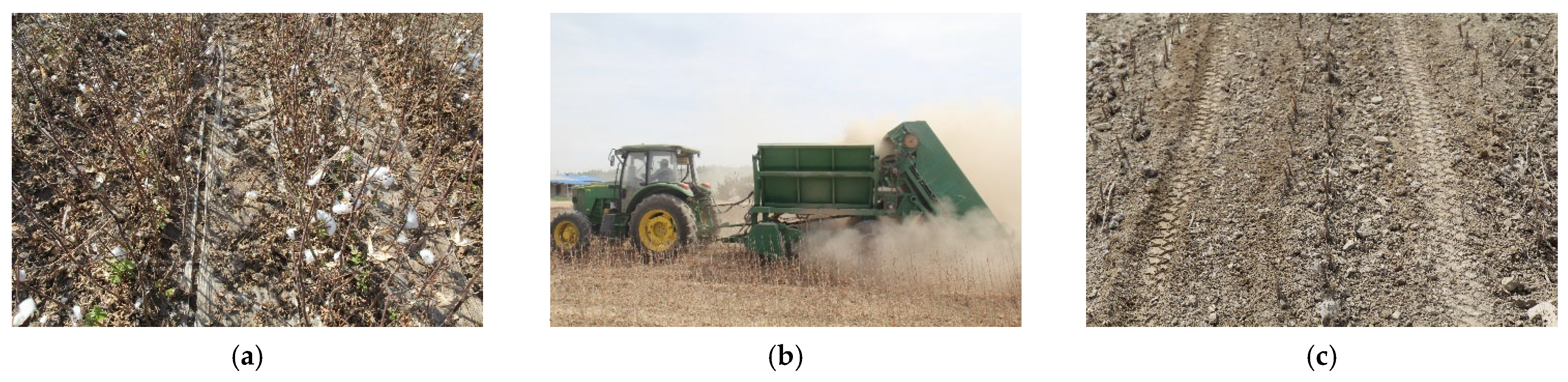
The condition of residual film separation occurs when the residual film moves to the de-filming area under the action of centrifugal force to overcome the chain tooth rake adsorption winding role and separation. Because of the inertia force of the film movement and the softness and easy adsorption of the film, the machine adopts the rotating scraper to remove the film. The scraper works close to the middle or end of the hook teeth, and there is elastic and plastic deformation between the hook teeth and the scraper in the contact process [18].
As shown in Figure 11, in the process of de-filming, when the residual film held by the hook moves to the de-filming area, the motion of the hook tooth assembly is deflected, the hook tooth tends to be vertical, and the film hanging on the hook tooth is relaxed and slips off under the action of gravity. At this time, the scraper produces a reverse scraping or slapping effect on the hook tooth assembly, and the film is scraped off the hook tooth and falls into the film box for collection after the de-filming operation.
The force analysis of the residual film separation moment is shown in Figure 11. The electrostatic adsorption force between the film and the scraper is very small, so its influence is ignored. When the hook tooth assembly is tilted to convey the residual film, its rotation radius tends to infinity, so Fb tends to 0. In the process of film removal, when the film removal device and the hook tooth assembly move relative to each other, the condition that the residual film is separated from the hook tooth at this time is
F 1 cos β + F n sin γ   >   f cos γ F n cos γ + f sin γ   <   F 1 sin β + G
where F1 = 22rt and G = mg.
Collation is obtained.
m   ω 2 2 r t cos β + m   g cos γ sin γ   >   μ m   g   cos 2 γ m   g   cos 2 γ + μ m   g cos γ sin γ   <   m   ω 2 2 r t sin β + m   g
where F1 is the force of the stripping device on the hook tooth (N); Fn is the support force of the hook tooth on the residual film (N); m is the mass of the residual film carried by the hook tooth (g); G is the gravity of the residual film (N); rt is the rotation radius of the stripping device m. g is the acceleration of gravity, m/s2; ω2 is the angular velocity of rotation of the de-filming axis rad/s; f is the friction force between the residual film and the hook tooth (N); Fb is the centripetal force generated by the motion of the residual film (N); β is the angle between the center of the de-filming axis and the line connecting the contact point and the horizontal direction (°); γ is the angle between the hook tooth rod and the vertical direction during the de-filming operation (°).

2.4. Field Tests

2.4.1. Test Materials

The picking device is driven by a John Deere tractor (tractor model 6A-1024, rated power 88.2 kW). The test instruments consist of an electronic balance (model: YP2002 electronic balance, range: 0–500 g, accuracy: 0.001 g), a measuring tape (range: 50 m), a Topun soil moisture tester (model: TZS-1K-G), a Topun soil compactness tester (model: TJSD-750-2), a cling bag, a stopwatch, label paper, and a marker pen.
The film width of the test cotton field was 2050 mm, the film thickness was 0.01 mm, and the longitudinal film length was approximately 340 m. The trial field’s film surface was flat, the drip irrigation tape had been recovered prior to the trial, and there were a few broken remnants of film, a few boll husks, leaves, and soil on the film surface. The grey desert soil moisture content was 19.29%, and the grey desert soil firmness was 5182.32 kPa.

2.4.2. Test Methods

Field tests were carried out on a picking device with reference to the national standard GB/T 25412-2010 Residual Film Recycler. There were 17 test areas, and the length of each was 100 m, while the width was one film width (2.05 m). 3 points were randomly selected from each test area as test points, each test point was 10 m in length, and the average value of the 3 test points was taken as the test result for that stroke. The residual film pick-up rate μ1 and the residual film impurity rate μ2 were determined as test indicators in conjunction with the actual operation. Use Formula (28) to calculate the residual film pick-up rate and Formula (29) to calculate the residual film impurity rate. Before the test, the total mass G1, of the film laid at the test site was calculated by measuring the film mass of one square meter by electronic balance. After the test, the residual film left at each detection point was collected, and the total mass of the residual film G2, was measured by electronic balance. The total mass of residual film impurities G3, was measured by electronic scale. The impurities in the residual film of the cleaning machine were manually picked up, and the mass G4, of the impurities was measured by an electronic balance.
μ 1 = G 1 G 2 G 1 × 100 %
μ 2 = G 4 G 3 × 100 %
where μ1 is the residual film pick-up rate %; μ2 is the residual film impurity rate %; G1 is the total mass of film laid at the test points in the test plot g; G2 is the mass of residual film left at each test point g; G3 is the total mass of film impurities g; G4 is the mass of impurities in the film impurities g.
The machine advancing velocity, the depth of hook tooth, and the chain rake input speed are the three main factors influencing the effect of residual film picking and residual film separation, according to the structure and working principle of the picking device. The machine advancing velocity of the implement is determined by the tractor’s travel speed, and the best velocity of the implement is 1.5 m/s, according to the subject group’s research. Given that the actual situation in the field differs from that on the experimental bench, the range is set at 0.5 m/s. Hook teeth into the soil depth will affect the machine’s operational effect to some extent; according to the structural design of the machine tail depth limit wheel, the hook teeth minimum depth should be 20 mm, the maximum depth should be 62 mm, and the rake teeth should be set into the soil depth level at 20, 40, and 60 mm. The previous theoretical analysis determined that the chain rake input speed is 210, 234, and 258 rpm.
In this paper, a three-factor, three-level response surface approach was used to design the experiment for the operation of the picking device in the field, and the experimental factors were coded as shown in Table 2.

2.4.3. Test Results

The experiment was designed using Design Expert 12.0 software (Stat-Ease Inc., Minneapolis, MN, USA), and 17 trial areas were arranged, with 1 trial in each, for a total of 17 sets of trials. Calculate the residua film pick-up rate using Formula (28), the residual film impurity rate using Formula (29), and the specific test scheme and results are shown in Table 3.

3. Results and Discussion

As shown in Table 4, we used Design Expert software to analyze the test results and the multiple regression fit. Table 4 shows the results of the residua film pick-up rate and residua film impurity rate variance analyses. The significance of the regression equations of μ1 and μ2 on X1, X2, and X3 was tested.
(1)
Establishment of the regression equation and significance analysis of the residual film pick-up rate
According to the model ANOVA, the order of significance of the test factors affecting the residual film pick-up rate is X1 > X3 > X2. The p-value of 0.0763 for the lack of fit of the residue picking rate was not significant, indicating that the regression model was valid and accurate, and that it could be used to analyze and predict the residue picking rate [19]. After removing the non-significant term, the regression equation for each factor’s effect on the residual film pick-up rate μ1 was as follows:
μ 1 = 88.06 + 1.42 X 1 + 0.50 X 3 + 0.77 X 1 X 2 + 2.18 X 1 X 3 4.39 X 1 2 1.89 X 2 2 2.04 X 3 2
(2)
Establishment of the regression equation and significance analysis of the residual film impurity rate
According to the model ANOVA, the order of significance of the test factors affecting the residual film impurity rate is X1 > X3 > X2. The p-value of 0.1549, for the lack of fit of the residual film impurity rate, was not significant, indicating that the regression model was valid and accurate, and that it could be used to analyze and predict the residual film impurity rate. After removing the non-significant term, the regression equation for each factor’s effect on the residual film impurity rate μ2 was as follows:
μ 2 = 10.22 0.96 X 1 + 0.36 X 2 0.62 X 3 0.45 X 1 X 2 1.47 X 1 X 3 + 2.84 X 1 2 + 1.34 X 2 2 + 1.32 X 3 2

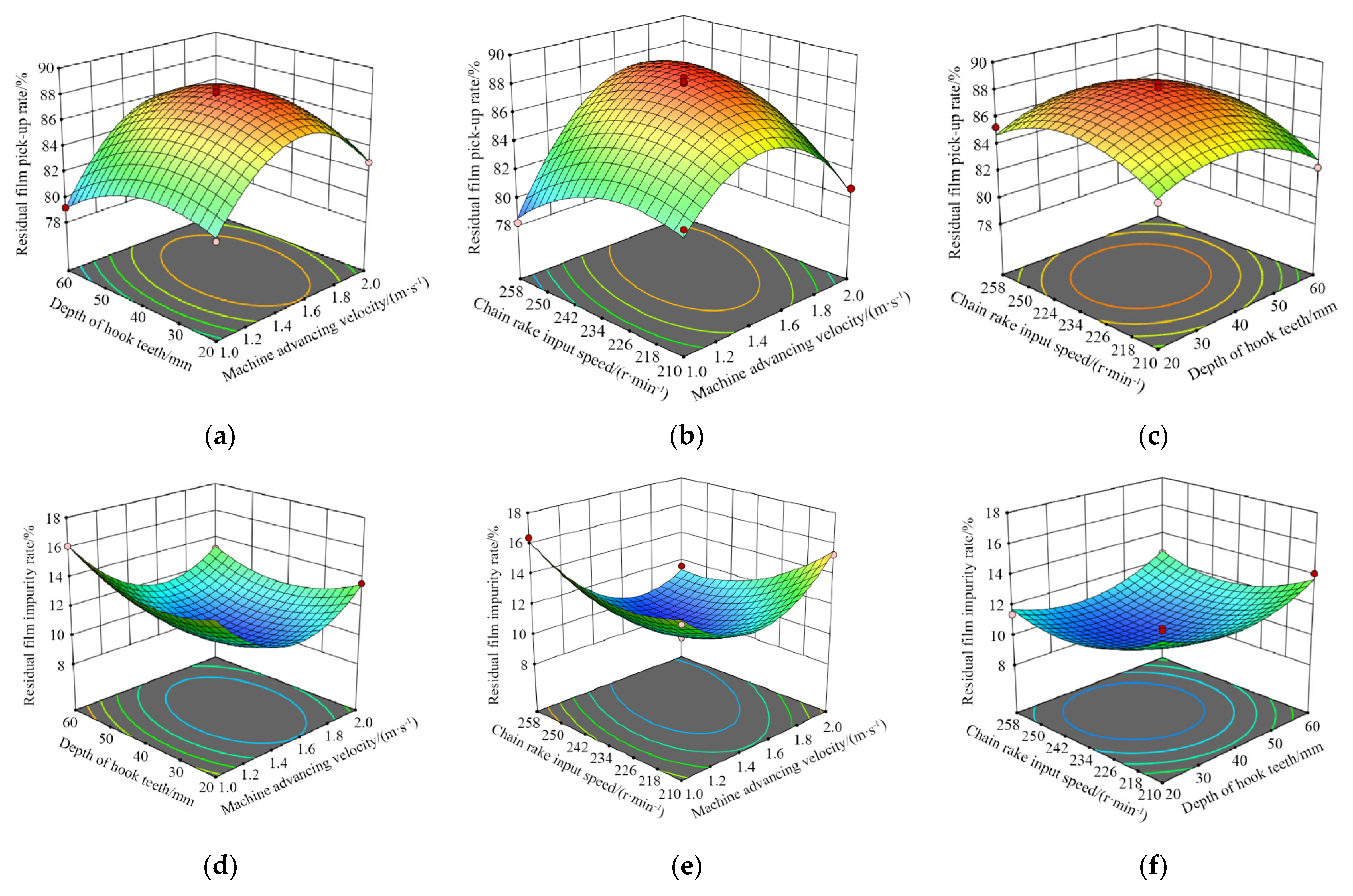
3.1. Response Surface Analysis

Field trials were conducted in October 2021 in Beiquan Town, Shihezi City, Xinjiang, to test the machine’s reliability and operational effectiveness, and to determine the optimum operating parameters. Figure 12 depicts the prototype field tests. At the same time, we used Design-Expert 12.0 software to create a response surface diagram. Figure 13 depicts an analysis of the interaction of the factors affecting pick-up rate and impurity rate.
(1)
Analysis of the influence of the residual film pick-up rate
Figure 13a depicts the effect of the interaction between X1 and X2 on the residual film pick-up rate when X3 is at the central level (234 rpm). As shown in the graph, the residual film pick-up rate in X1 and X2 of interaction increases first and then decreases, with X1 increasing first and then decreasing, and X2 increasing first and then decreasing. On the residual film pick-up rate response surface, Figure 13b for X2 is located in the center level (40 mm) of the X1 and X3 interaction. As shown in the graph, the residual film pick-up rate increases and then decreases due to the interaction between X1 and X3, and increases and then decreases as X1 increases, and increases and then decreases as X3 increases; Figure 13c depicts the response of X1 at the center level (1.5 m/s), as well as the interaction between X2 and X3. The graph depicts the effect of X2 and X3 interaction on the film pick-up rate. As shown in the graph, the residual film pick-up rate in X2 and X3 interactions increases first and then decreases, with X2 increasing first and then decreasing, and X3 increasing first and then decreasing [20,21].
The main reasons for this are: the slower X1, the poorer the ability of the hook teeth to pick up film continuously per unit length, and the subsequent hook teeth cannot pick up residual film sufficiently, resulting in a lower rate of picking up residual film. The faster X1, the easier it is for the hook teeth to tear the residual film per unit length, which will also cause the residual film pick-up rate to decrease; X2 has no significant effect on the residual film pick-up rate, which is due to the fact that the residual film in the field is mainly concentrated in the surface layer of the soil, so it is difficult to increase X2 to improve the residual film pick-up rate; when X3 is slower, the hook teeth are subject to soil resistance for a longer period of time and are easily de-formed and damaged, resulting in the pick-up residual film performance decline. When X3 is faster, the hook teeth will cause a large impact on the residual film, which is not conducive to pick-up of the residual film.
(2)
Effect of factor interaction of the residual film impurity rate
Figure 13d depicts the response surface plot of the interaction between X1 and X2 on the residual film rate when X3 is at the central level (234 rpm). As shown in the figure, the residual film impurity rate in X1 and X2 of interaction under the influence of the first decrease and then increase, with X1 increasing first decrease and then increasing, and X2 increasing first decrease and then increasing; Figure 13e shows an interaction of X1 and X3 on the residual film impurity rate of response surface diagram with X2 located in the center of the level (40 mm). The residual film impurity rate in X1 and X3 interactions can be seen in the figure, with X1 increases first decreasing and then increasing, and X3 increases first decreasing and then increasing. In Figure 13f, X1 is located in the center of the level (1.5 m/s), and X2 and X3 interact on the residual film impurity rate response surface plot. The graph depicts the effect of the interaction between X2 and X3 on the residual film impurity rate. As shown in the graph, the residual film impurity rate in X2 and X3 interactions is first reduced and then increased, with X2 increases first reduced and then increased, and X3 increases first reduced and then increased.
The main reasons for the above are: the slower X1, the faster the hook teeth disturb the soil per unit length, resulting in an increase in the proportion of impurities picked up. The faster X1, the lower the residual film picking capacity of the hook teeth, but the picking of impurities on the film surface remains at a high level, resulting in a higher rate of residual film impurity. If X2 is too shallow, the amount of residual film picked up decreases, but the rate of picking up impurities on the film surface increases. If X2 is too deep, the impurities in the tillage layer will be picked up, resulting in a higher residual film impurity rate. When X3 is too slow, the hook teeth are subject to greater resistance from the soil and are easily deformed and damaged, which is not conducive to the picking up of the residual film, but the effect of picking up the impurities on the residual film surface is not significant and can also cause the residual film impurity rate to be higher. When X3 is too fast, the cleaning device’s duration of time for cleaning impurities is shorter, and the impurities cannot be separated in time, resulting in a higher residual film impurity rate.

3.2. Parameter Optimization and Test Validation

To optimize the prototype’s performance, a multi-objective optimization of the residual film pick-up rate and residual film impurity rate was performed using the Design-Experimentation module [22,23,24]. The optimization intervals were set to be the upper and lower limits of the test factors, with the goals of increasing the residual film pick-up rate and decreasing the residual film impurity rate. The optimization conditions in the software are set to dual-objective equal-weight optimization, with the following constraints:
μ 1 m a x = F X 1 , X 2 , X 3 μ 2 m i n = F X 1 , X 2 , X 3 s . t X 1 1.0 , 2.0 X 2 20.0 , 60.0 X 3 210.0 , 258.0
The optimization and solution of the objective function for the optimal parameter combination was as follows: machine advancing velocity was 1.62 m/s, depth of hook tooth was 38.51 mm, and chain rake input speed was 241.42 rpm, yielding a predicted residual film pick-up rate of 88.27% and a residual film impurity rate of 9.96%. The optimized operating parameters for rounding were 1.6 m/s machine advancing velocity, a 39 mm depth of hook tooth, and a 241 rpm chain rake input speed based on the actual test conditions in the field. The above parameters were used for three replicate tests to obtain more accurate experimental results, and the average value was used as the final test result. The actual residual film pick-up rate was 87.52%, and the residual film impurity rate was 10.12%, as shown in Table 5. The relative error between actual and theoretical values was less than 5%, indicating that the optimisation results obtained with Design-Expert 12.0 software were reliable.

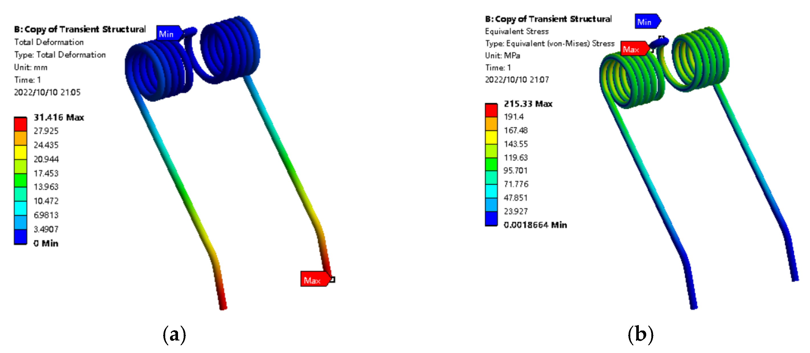
3.3. Discrete Element Modeling of Hook Tooth Motion Process

3.3.1. Modeling and Parameter Setting of the Simulation Model

To further investigate the force on the hook teeth during the operation of the pickup device, simulation tests were performed using EDEM. To accurately simulate the interaction between the hook teeth and the soil during the actual operation, the radius of the soil particles, as shown in Figure 14a, was set to 3 mm, and the contact model of the soil particles was created in EDEM 2018 (DEM Solutions Ltd. Edinburgh, Scotland, UK) using the Hertz–Mindlin with Bonding model. Then, create a 3D model structure of the simplified hook tooth using SolidWorks 2018 software (Dassault Systèmes S.E., Massachusetts, Concord, MA, USA), save it as a “.x_t” format file, and import it into EDEM 2018.
The soil trough is modeled in EDEM software with dimensions L × W × H = (1250 × 1000 × 250) mm. In order to simulate the actual motion law of the hook tooth, according to the results of the previous analysis, set the front end of the hook tooth just touching the soil as the starting position, set the horizontal forward speed to 1.62 m/s, the chain rake input speed to 241 rpm, and the hook tooth simulation model operation process as shown in Figure 14b.
The simulation time step is set to 1.5 × 10⁻⁶, the simulation time is one second, and the grid cell size is 3 times the minimum soil particle size. The contact model is chosen from soil particles and a hook tooth, and the main parameters are contact parameters and intrinsic parameters, with the contact parameters being soil recovery coefficient, static friction coefficient, and dynamic friction coefficient, and the intrinsic parameters being density, Poisson’s ratio, and shear modulus. The data for the main parameters of the discrete element method test model were obtained using the method of calibration and optimization of the stacking test discrete element parameters [25,26,27], in which the soil parameters were obtained from the gray desert soil, which itself is the most widely distributed soil type in Shihezi, Xinjiang. The relevant parameters are shown in Table 6.

3.3.2. Analysis of Simulation Results

When the simulation process is finished, the post-processing module of EDEM software is entered, and the maximum force on the hook tooth is obtained as 60.7 N. ANSYS software analyzes the stress and deformation of the hook tooth under maximum force, and the loading area is set to the hook tooth’s working surface with a depth of 38.51 mm [28]. Under the condition of complete constraint of the hook tooth installation center, the load on the surface of the hook tooth is 60.7 N, the loading direction of the surface of the hook tooth is set to be the same as the direction of the instantaneous rotation of the tooth tip, and the load on the surface of the hook tooth is configured to be evenly distributed in order to simplify the calculation and improve the calculation speed.
Figure 15a depicts the hook tooth deformation cloud. The maximum deformation of the hook tooth occurs at the end, with a deformation of 31.42 mm, which is relatively small in comparison to the entire hook tooth. The hook teeth are made of spring steel, which has the ability to deform elastically and can withstand a certain load without permanent deformation after the load is removed. Figure 15b depicts the stress cloud of the hook tooth. The maximum strain occurs at the connection between the hook tooth and the threaded fastener, and the stress value is 215.33 MPa. The yield strength of the hook tooth is [σb] = 1230 MPa, and while this time the safety factor under the established working conditions is 5.71, the stress value is much less than the allowable stress, so the hook tooth design meets the requirements.

4. Conclusions

1.
In response to the problems of high residual film pick-up rate and poor reliability of the existing film recovery machine, a Hook-and-Tooth Chain Rail Type Residual Film Picking Device was designed, introducing the structure and working principle of the main components. By analyzing the main working components of the picking device, the main design parameters of its components were determined.
2.
Field tests were carried out with the machine advancing velocity, depth of hook tooth, and chain rake input speed as influencing factors and the residual film pick-up rate and residual film impurity rate as test indicators. Additionally, the response surface data were analyzed using Design Expert software, and multiple fittings obtained the regression equation of the residual film pick-up rate and the residual film impurity rate. The influence of the interaction of various factors on the residual film pick-up rate and the residual film impurity rate was determined.
3.
Experimental tests on the device proved that when the machine advancing velocity was 1.6 m/s, the depth of the hook tooth was 38 mm, and the chain rake input speed was 241 rpm. With these working parameters, field trials yielded a residual film pick-up rate of 87.52% and a residual film impurity rate of 10.21%. The optimized operating parameters were verified experimentally. Relative errors between the experimental results and optimized theoretical values of the residual film pick-up rate and residual film impurity rate were 0.85% and 2.51%, respectively, which is relatively low. Thus, the model was highly reliable.
4.
EDEM simulated the motion process of the hook tooth and obtained the maximum force on the hook tooth during the working process. Then, ANSYS software was used to analyze the stress and deformation of the hook tooth under the state of maximum force, and the structural strength of the hook tooth was verified to meet the design requirements.

Author Contributions

Conceptualization, methodology, writing—original draft, J.X. and S.C.; writing—review and editing, H.W. and Y.Y.; software, H.W. and Y.Z.; investigation, H.W. and Y.Z.; data curation, J.Z. and S.W.; funding acquisition, J.X. and S.C.; validation, S.C.; All authors have read and agreed to the published version of the manuscript.

Funding

This research was funded by the National Natural Science Foundation of China funded project (51965058), Corps Young and Middle-Aged Leading Talents Program Project (2018CB011), and research and development of high quality and efficient separation machinery and equipment for cotton straw and residual film leaving the field (2022B02033-2).

Institutional Review Board Statement

Not applicable.

Informed Consent Statement

Not applicable.

Data Availability Statement

All relevant data presented in the article are stored according to institutional requirements and, as such, are not available online. However, all data used in this Manuscript can be made available upon request to the authors.

Conflicts of Interest

The authors declare no conflict of interest.

References

  1. Zhao, Y.; Chen, X.; Wen, H.; Zheng, X.; Niu, Q.; Kang, J. Research Status and Prospect of Control Technology for Residual Plastic Film Pollution in Farmland. Trans. Chin. Soc. Mach. 2017, 48, 1–14. [Google Scholar] [CrossRef]
  2. Yan, C.; Mei, X.; He, W.; Zheng, S. Present situation of residue pollution of mulching plastic film and controlling measures. Trans. Chin. Soc. Agric. Eng. 2006, 22, 269–272. [Google Scholar]
  3. Wang, Z.; Chen, X.; Yan, L.; Jiang, D.; Wang, M. Design and Experiment on Collecting and Removing Device for Profile Modeling Residual Plastic Film Collector. Trans. Chin. Soc. Mach. 2021, 52, 80–90. [Google Scholar] [CrossRef]
  4. Hu, C.; Wang, X.F.; Chen, X.G.; Tang, X.Y.; Zhao, Y.; Yan, C. Current situation and control strategies of residual film pollution in Xinjiang. Trans. Chin. Soc. Agric. Eng. 2019, 35, 223–234. [Google Scholar] [CrossRef]
  5. Lavo, G. Machine for Removing Wide Strips Laid Out on the Ground. 1995. Available online: https://patents.google.com/patent/US5386876A (accessed on 8 August 2022).
  6. Parish, R.L. An automated machine for removal of plastic mulch. Trans. ASAE 1999, 45, 49. [Google Scholar] [CrossRef]
  7. Rocca, A.R. Plastic Mulch Retrieve. 2012. Available online: https://patents.google.com/patent/US8302699B2 (accessed on 8 August 2022).
  8. Shi, Z.L.; Tang, X.P.; Zhen, J.; Yan, J.S.; Zhang, X.J.; Jin, W. Performance test and motion simulation analysis of nail tooth type mechanism for collecting plastic residue. Trans. Chin. Soc. Agric. Eng. 2019, 35, 64–71. [Google Scholar] [CrossRef]
  9. Liu, X.F.; Shi, X.; Guo, Z.F.; Wang, C.Y.; Wang, X.N. Performance test on roller type residual film recycling machine. Trans. Chin. Soc. Agric. Eng. 2017, 33, 26–31. [Google Scholar] [CrossRef]
  10. Tang, Y.; Zhao, Y.; Wang, J.; Wang, Z. Design and experiment of film removing device for clamping finger-chain type residual film collector. Trans. Chin. Soc. Agric. Eng. 2020, 36, 11–19. [Google Scholar] [CrossRef]
  11. Zhang, X.J.; Liu, J.Q.; Shi, Z.L.; Jin, W.; Yan, J.S.; Yu, M.J. Design and parameter optimization of reverse membrane and soil separation device for residual film recovery machine. Trans. Chin. Soc. Agric. Eng. 2019, 35, 46–55. [Google Scholar] [CrossRef]
  12. Guo, W.; Jian, J.; San, Y.; Li, G.; Gao, M.; Hou, S. Design and Experimental Optimization of 4CML-1000 Type Chain Rake Film Recycling Machine. Trans. Chin. Soc. Mach. 2018, 49, 66–73. [Google Scholar] [CrossRef]
  13. Xie, J.; Yang, Y.; Cao, S.; Zhang, Y.; Zhou, Y.; Ma, W. Design and experiments of rake type surface residual film recycling machine with guide chain. Trans. Chin. Soc. Agric. Eng. 2020, 36, 76–86. [Google Scholar] [CrossRef]
  14. Yin, J.; Liu, D.; Li, Y. Design and Parameters Analyses of Automatic Height Profiling Device of Quadrate-Bale Baler Pickup. Trans. Chin. Soc. Mach. 2014, 45, 86–92. [Google Scholar] [CrossRef]
  15. Kang, J.; Wang, S.; Yan, L. Design and Experiment of Loosen Shovel Installed on Plastic Film Collecting Machine. Trans. Chin. Soc. Mach. 2016, 47, 143–148. [Google Scholar] [CrossRef]
  16. Cheng, D.X. Handbook of Mechanical Design; Chemical Industry Press: Beijing, China, 2008. [Google Scholar]
  17. Zheng, Z.Q.; He, J.; Wang, Q.J.; Li, H.W.; Li, W.Y.; Chen, W.Z. Design and Experiment on Straw Pickup-chopping and Ditch-burying Integrated Machine. Trans. Chin. Soc. Mach. 2017, 48, 87–96. [Google Scholar] [CrossRef]
  18. Yang, S.; Yan, L.; Mo, Y.; Chen, X.; Zhang, H.; Jiang, D. Design and Experiment on Collecting Device for Profile Modeling Residual Plastic Film Collector. Trans. Chin. Soc. Mach. 2018, 49, 109–115+164. [Google Scholar] [CrossRef]
  19. Luo, K.; Yuan, P.; Jin, W.; Yan, J.S.; Bai, S.; Zhang, C.; Zhang, X.J. Design of chain-sieve type residual film recovery machine in plough layer and optimization of its working parameters. Trans. Chin. Soc. Agric. Eng. 2018, 34, 19–27. [Google Scholar] [CrossRef]
  20. Yan, W.; Hu, Z.; Wu, N.; Xu, H.; You, Z.; Zhou, X. Parameter optimization and experiment for plastic film transport mechanism of shovel screen type plastic film residue collector. Trans. Chin. Soc. Agric. Eng. 2017, 33, 17–24. [Google Scholar] [CrossRef]
  21. Xie, J.; Zhang, F.; Chen, X.; Han, Y.J.; Tang, W. Design and parameter optimization of arc tooth and rolling bundle type plastic film residue collector. Trans. Chin. Soc. Agric. Eng. 2019, 35, 26–37. [Google Scholar] [CrossRef]
  22. You, J.; Chen, X.; Zhang, B.; Wu, J. Design and experiment of 4JSM-2000 type combined operation machine for cotton stalk chopping and residual plastic film collecting. Trans. Chin. Soc. Agric. Eng. 2017, 33, 10–16. [Google Scholar] [CrossRef]
  23. You, Z.; Hu, Z.; Wu, H.; Zhang, Y.; Yan, J.; Yan, W.; Zhou, X. Design and experiment of 1MCDS-100A typed shovel-sieve residual film recovery machine. Trans. Chin. Soc. Agric. Eng. 2017, 33, 10–18. [Google Scholar]
  24. Zhang, Z.; Li, J.; Wang, X.; Zhao, Y.; Xue, S.; Su, Z. Parameters Optimization and Test of an Arc-Shaped Nail-Tooth Roller-Type Recovery Machine for Sowing Layer Residual Film. Agriculture 2022, 12, 660. [Google Scholar] [CrossRef]
  25. Zhong, W.Q.; Yu, A.B.; Liu, X.J.; Tong, Z.B.; Zhang, H. DEM/CFD-DEM Modelling of Non-spherical Particulate Systems: Theoretical Developments and Applications. Powder Technol. 2016, 302, 108–152. [Google Scholar] [CrossRef]
  26. Wu, T.; Huang, W.; Chen, X.; Ma, X.; Han, Z.; Pan, T. Calibration of discrete element model parameters for cohesive soil considering the cohesion between particles. J. South China Agric. Univ. 2017, 38, 93–98. [Google Scholar] [CrossRef]
  27. Wang, X.; Hu, H.; Wang, Q.; Li, H.; He, J.; Chen, W. Calibration method of soil contact characteristic parameters based on DEM theory. Trans. Chin. Soc. Mach. 2017, 48, 78–85. [Google Scholar] [CrossRef]
  28. Wang, H.; Cao, S.; Liu, Y.; Yang, Y.; Meng, X.; Ji, P. Design of Cotton Recovery Device and Operation Parameters Optimization. Agriculture 2022, 12, 1296. [Google Scholar] [CrossRef]
Figure 1. The residual film recycling machine: 1. Traction frame; 2. Power transmission system; 3. Straw crushing device; 4. Mulch storage and pushing out device; 5. Machine frame; 6. Wheels; 7. Hook-and-tooth chain rail type residual film picking device.
Agriculture 12 01717 g001
Figure 2. Hook-and-tooth chain rail type film picking device: 1. Chained rake frame upper shaft assembly; 2. Hook tooth assembly; 3. Guide beam; 4. Curved edge conveyor chain; 5. Chain rake frame lower shaft assembly; 6. Flap for discharging debris; 7. Chain rake frame; 8. Mounting plate; 9. De-filming shaft; 10. Prevention of mulch sucking back parts; 11. Articulated short shaft. (a) the main components of the picking device, (b) Pick up film chain rake structure schematic diagram.
Agriculture 12 01717 g002
Figure 3. A schematic diagram of the hook and tooth assembly structure: 1. Limit short shaft; 2. Guide side plate; 3. Roller; 4. Hook tooth mounting shaft; 5. Hook tooth; 6. Threaded fastener.
Agriculture 12 01717 g003
Figure 4. A schematic diagram of the rotation of the decapping area of the hook tooth assembly: 1. Hook tooth mounting shaft; 2. Hook tooth; 3. Short shaft; 4. Side guide plate; 5. Roller.
Agriculture 12 01717 g004
Figure 5. A schematic diagram of the hook tooth structure: (a) Diagram of the influence of resistance of hook teeth into the soil; (b) Axonometric drawing.
Agriculture 12 01717 g005
Figure 6. The spread layout of the film picking teeth.
Agriculture 12 01717 g006
Figure 7. Working process of the film pickup device. (a) Picking film process diagram, (b) Motion diagram of the pick-up hook tooth.
Agriculture 12 01717 g007
Figure 9. The motion track of two adjacent film-picking hook teeth on the conveying chain rake.
Agriculture 12 01717 g009
Figure 10. A force analysis diagram of residual film in the conveying process.
Agriculture 12 01717 g010
Figure 11. A schematic diagram of the forces on the residual film during the de-filming process.
Agriculture 12 01717 g011
Figure 12. A field test of the experimental device. (a) Before the test; (b) The test process; (c) After the test.
Agriculture 12 01717 g012
Figure 13. The effects of the interaction of various factors on the picking rate and trash content of cotton fallen on the ground. (a). μ1 = (X1, X2, 234); (b). μ1 = (X1,40, X3); (c). μ1 = (1.5, X2, X3); (d). μ2 = (X1, X2, 234); (e). μ2 = (X1, 40, X3); (f). μ2 = (1.5, X2, X3).
Agriculture 12 01717 g013
Figure 14. A particle and geometric simulation model. (a) Particle model of the soil; (b) simulation model of the EDEM.
Agriculture 12 01717 g014
Figure 15. The analysis results. (a) Hook tooth deformation cloud map; (b) Hook tooth stress cloud.
Agriculture 12 01717 g015
Table 1. The main working parameters of a picking device.
Main Parameters of the Picking DeviceValue
Structure formTraction type
Dimension (length × width × height)/mm2240 × 880 × 3170
Matched power/kW88.20
Operating speed/(km·h−1)4–8
Effective operating width/mm1875
Residual film pick-up rate/%≥85
Residual film impurity rate/%≤12
Table 2. The test factors and levels.
Coded
Value
Machine Advancing
Velocity X1 (m·s−1)
Depth of Hook
Tooth X2 (mm)
Chain Rake Input Speed X3 (rpm)
−11.020210
01.540234
12.060258
Table 3. The test plans and results.
TestX1X2X3μ1μ2
10−1−184.113.4
211083.813.2
310185.211.6
400087.610.5
500088.59.8
61−1082.813.6
700088.110.2
810−180.715.3
901−182.314.1
10−10−182.414.2
1101184.812.6
1200088.210.3
1300087.910.3
140−1185.311.4
15−10178.216.4
16−1−1081.314.7
17−11079.216.1
Table 4. The analysis of variance of the regression equation.
Source of
Variation
DOFResidua Film Pick-Up Rate μ1/%Residua Film Impurity Rate μ2/%
Sum of SquaresFSignificant
Level p
Sum of SquaresFSignificant
Level p
Models9165.944.46<0.0001 **74.6365.92<0.0001 **
X1116.2419.220.0001 **7.4158.920.0001 **
X211.443.010.06711.058.360.0233 *
X312.001.610.0382 *3.1324.840.0016 **
X1 X212.40259.680.0268 *0.81006.440.0388 *
X1 X3118.923.58<0.0001 **8.7069.19<0.0001 **
X2 X310.42250.700.27990.06250.49690.5036
X12181.240.23<0.0001 **33.96269.99<0.0001 **
X22115.081.890.0002 **7.5660.110.0001 **
X32117.570.250.0001 **7.2857.880.0001 **
Residual72.16 0.8805
Lack of fit31.701.960.07630.61253.050.1549
Pure error40.4520 0.2680
Total16168.10 75.51
Note: ** means highly significant (p < 0.01), and * means significant (0.01 ≤ p < 0.05).
Table 5. A comparison between the optimum theoretical and test results.
ParameterResidua Film
Pick-Up Rate μ1/%
Residua Film
Impurity Rate μ2/%
Theoretical optimization value88.279.96
Test average87.5210.12
Relative error0.852.51
Table 6. The simulation parameter settings of soil particles and geometry.
ItemParameterValue
Soil particlesPoisson’s ratio0.30
Shear modulus/Pa5 × 107
Density/(kg·m−3)2600.00
Hook teethPoisson’s ratio0.35
Shear modulus/Pa7.27 × 1010
Density/(kg·m−3)7890.00
Soil particles-Soil particlesRecovery coefficient0.21
Static friction coefficient0.68
Dynamic friction coefficient0.27
Soil particles-Hook teethRecovery coefficient0.32
Static friction coefficient0.54
Dynamic friction coefficient0.13
Publisher’s Note: MDPI stays neutral with regard to jurisdictional claims in published maps and institutional affiliations.

