Article

Study on the Distribution Pattern of Threshed Mixture by Drum-Shape Bar-Tooth Longitudinal Axial Flow Threshing and Separating Device

1
College of Engineering, Huazhong Agricultural University, Wuhan 430070, China
2
Key Laboratory of Agricultural Equipment in Mid-lower Yangtze River, Ministry of Agriculture and Rural Affairs, Wuhan 430070, China
3
Agricultural Engineering Department, Zagazig University, Zagazig 44519, Egypt
*
Author to whom correspondence should be addressed.
Agriculture 2021, 11(8), 756; https://doi.org/10.3390/agriculture11080756
Submission received: 11 June 2021 / Revised: 3 August 2021 / Accepted: 3 August 2021 / Published: 9 August 2021
(This article belongs to the Special Issue Agricultural Structures and Mechanization)

Abstract

:
To determine the distribution pattern of the threshing and separating device, the simulation experiment on the distribution pattern of our self-designed drum-shape bar-tooth longitudinal axial flow threshing and separating device was carried out with the help of the EDEM software, by which the axial and radial distribution curve of the threshed mixture along the cylinder was acquired. The three-dimensional distribution of the mass of the threshed mixture was drawn by using the Matlab software, and the bench test was carried out on the self-built small-scale longitudinal axial flow threshing cylinder performance test platform, which was consistent with the simulation conditions. The results showed that the axial and radial distribution of the threshed mixture was uneven, and the axial distribution of the threshed mixture decreased gradually, which was mainly distributed in the first third section of the cylinder. The distribution of the threshed mixture along the radial area of the cylinder was gradually decreasing at first and then increasing, i.e., the total mass of the threshed mixture on the left and right sides was higher than that of the middle area, which was basically consistent with the simulation results. The research can provide reference for the optimization of structural parameters of threshing and separating device and cleaning system.

1. Introduction

In the actual operation of the combine harvesters, the crops enter the threshing cleaning system through the header and conveying channel, and are threshed under the action of threshing elements, and then the threshed mixture falls onto the cleaning screen through the grain layer and concave screen under the centrifugal force [1]. The research on the distribution features of the threshed mixture can provide a reference for the parameter design of the cleaning system, and conditions for reducing the cleaning load and improving the grain cleanliness.
A large number of theoretical and experimental studies have been carried out on the distribution pattern of threshed mixture. Miu et al. [2] established a mathematical model for the distribution of the threshed mixture by an axial flow threshing device. The model described the distribution characteristics of the unthreshed grain, threshed grain, and free grain with the length of the cylinder in the threshing process, and analyzed the effects that the cylinder speed, feed rate, and crop moisture content had on grain separation. Li et al. [3] theoretically analyzed the working mechanism of the threshing and separating device and established a comprehensive mathematical model of the threshing and separating process from the angle of probability theory. Zhang et al. [4] studied the distribution pattern of the threshed mixture along the axial direction of the cylinder by using the self-developed axial flow threshing and separating device with helical blade and plate teeth. The results showed that the axial distribution of the threshed mixture was greatly affected by the grain distribution, and the grain distribution curve was prominent. The distribution pattern was similar under different feeding rates, and the peak value of the curve was higher when the feeding rate was large. Yi et al. [5,6,7] conducted an experimental study on the distribution pattern of the threshed mixture along the axial and tangential directions of the spiral blade strip-tooth and spike-tooth axial flow threshing and separating devices, and carried out a regression analysis on the distribution curve of each threshed mixture. The results showed that the degree of impurity and stem breakage of the spike-tooth axial flow threshing and separating device was higher than those of the combined device. Li et al. [8,9] conducted a comparative experimental study on the axial distribution of the threshed mixture from the short-striped bar-plate teeth and the spike-tooth cylinder. The results showed that the distribution of the threshed mixture from the short-striped bar-plate teeth was more even than that from the spike-tooth cylinder, and the impurity content of the threshed mixture was lower. Guo et al. [10] also conducted a comparative experimental study on the radial distribution of the threshed mixture from the trapezoidal plate tooth cylinder and spike-tooth cylinder. The results suggested that the threshed mixture from spike-tooth cylinder was more evenly distributed along the radial direction of the cylinder. Tang et al. [11] used self-made rectangular tooth plate, short grain rod-plate tooth, spike tooth, blade tooth, and trapezoidal plate tooth to test the threshing and separating performance of grain under the feeding rate of 7 kg/s and 8 kg/s, and compared the initial threshing and separating rate of tangential flow device under different threshing elements and the axial and radial distribution of threshing mixture of longitudinal axial flow re-threshing device under different threshing elements. Chen et al. [12] carried out a comparative experiment on the distribution pattern of the threshed mixture between the semi-feeding coaxial differential threshing cylinder and the single-speed threshing cylinder, and established a 3D image and its mathematical model with Matlab for the measured data of all kinds of threshed mixture. The results indicated that the distribution of all kinds of threshed mixture by the differential threshing cylinder was more evenly distributed on the screen. Chen et al. [13] conducted a single factor experiment on the axial and radial distribution changes of the longitudinal axial flow flexible threshing device. The results showed that the distribution of threshed mixture and seeds of longitudinal axial flow flexible threshing device conformed to the exponential function distribution, the distribution of pods and light impurities conforms to cubic function distribution, and the distribution of threshed mixture, seeds, pods, and light impurities conforms to the multinomial form with different coefficients.
The above researches show that the distribution of the threshed mixture was affected by the feeding mode of the crops, the structure of the threshing and separating device, the movement parameters, the feeding amount, the material characteristics, etc. Most of the existing researches on the distribution pattern of threshed mixture were conducted by combining theoretical models with bench test or field test. However, in the process of experiment, it is complex to collect and process the threshed mixture, which not only increases the difficulty of experiment, but also prolongs the experiment period.
Aiming at the above problems, this paper presents a mathematical model of threshing and separating based on the probability theory, which was based on the self-designed drum-shape bar-tooth longitudinal axial flow threshing and separating device. The distribution pattern of threshing was simulated and analyzed by using the EDEM (2018, DEM Solutions Ltd., 6th Floor, 1 Rutland Court, Edinburgh, EH3 8FL UK) software, and a bench test was also set up to verify the results, which could create conditions for optimizing the structural parameters of the threshing and separating device and cleaning system.

2. Materials and Methods

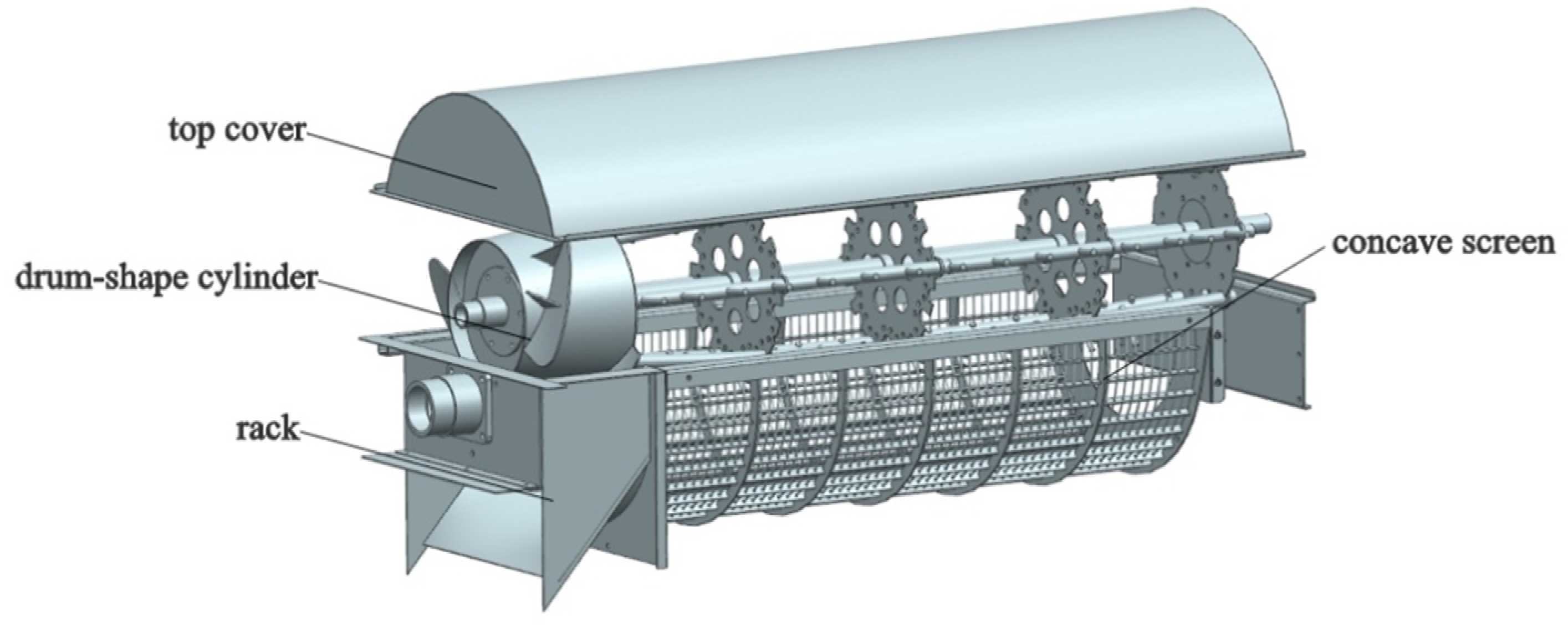
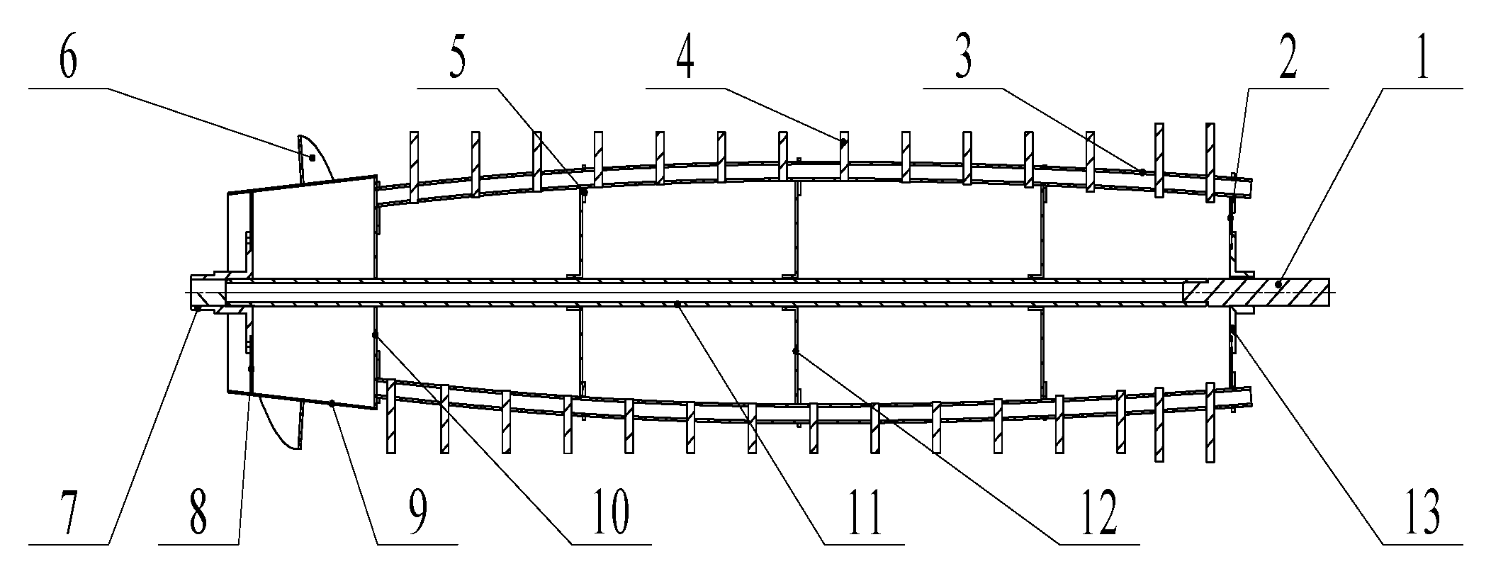
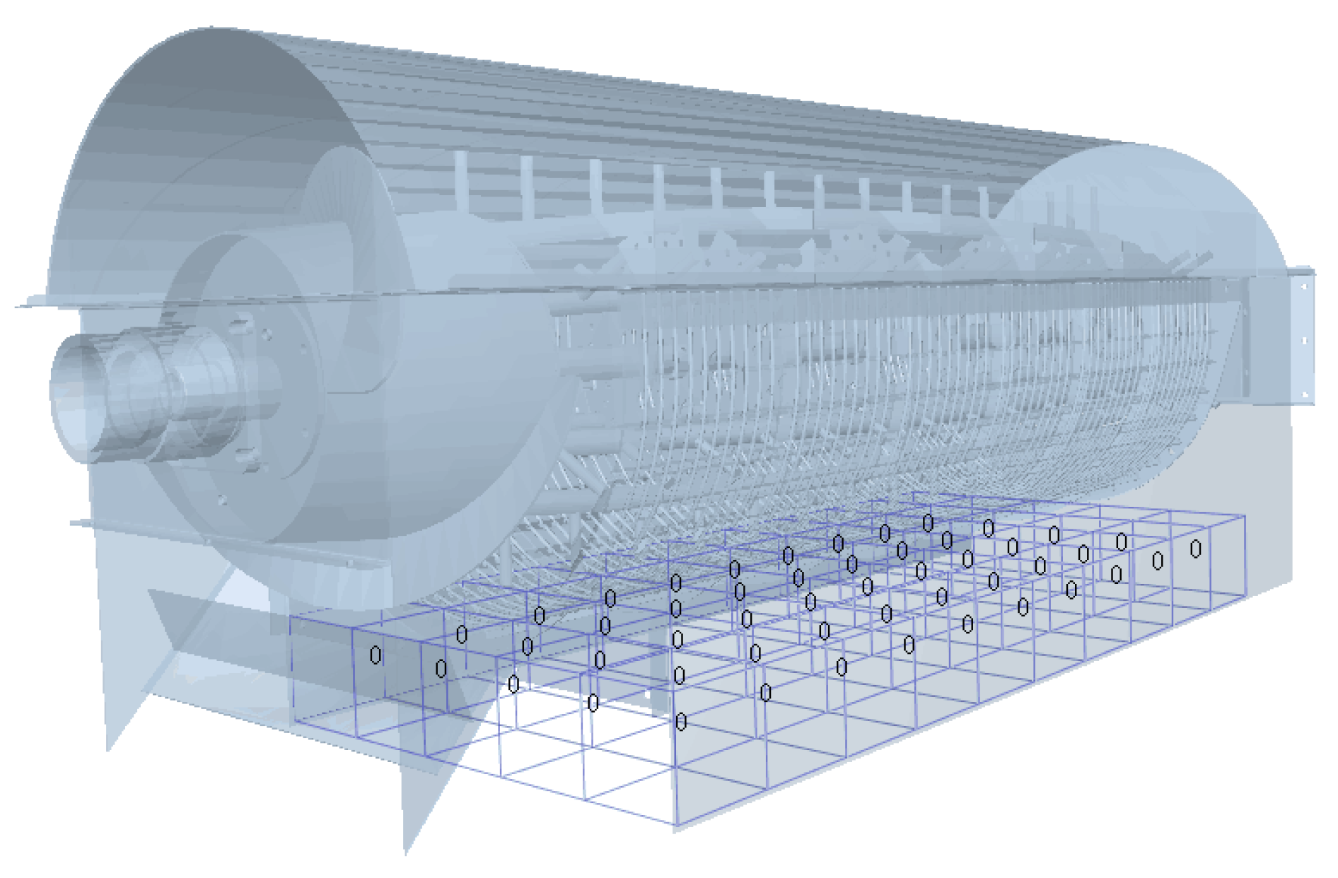
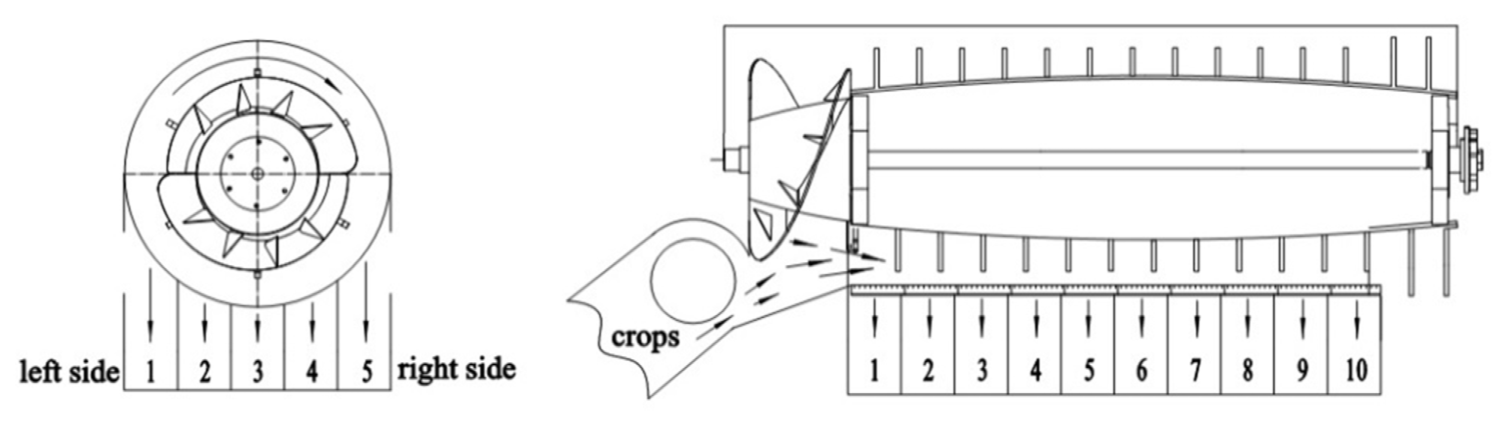
2.1. Structure of Longitudinal Axial-Flow Threshing and Separating Device

A drum-shape bar tooth longitudinal axial-flow threshing and separating device was designed with the reference to existing researches [14,15,16], which mainly consisted of a drum-shape cylinder, a concave screen, a top cover with guide plate, a rack, etc., as shown in Figure 1.
Its working principle is that the crops enter the threshing and separating device from the conveying channel, get into the threshing section under the grasping of the conical spiral feeding head, and take off and separate the rice grains from the earhead under continuous hitting, brushing, and rubbing of the bar tooth. At the same time, under the action of the cylinder and the guide plate, the rice plants make a spiral movement into the separating section. Under the centrifugal force generated by the high-speed rotation of the cylinder, the detached grains are continuously separated from the concave sieve, and the straw is discharged from the discharge section. Most of the grains are removed and separated in the first half of the threshing cylinder, and the second half mainly separates the free grains from the concave screen.
The traditional threshing cylinder with single longitudinal flow mainly consists of two types: cylindrical and conical. On the basis of the existing threshing cylinder structure, we designed a kind of drum-shape bar-tooth longitudinal axial flow threshing cylinder combined with the theoretical research and experimental analysis of scholars at home and abroad, which aimed at reducing drag and consumption. The cylinder was mainly composed of spiral feeding head, bar-tooth, wheel, and threshing teeth. The structure is shown in Figure 2.

2.2. Mathematical Model of the Threshing and Separating Process

The function of the threshing and separating device is to thresh the grain from the ear under the action of the threshing elements, and then allow the free grain to be separated from the concave screen through the grain layer under the centrifugal force generated by the high-speed rotation of the cylinder. It was hypothesized that it is equally likely for the grain to be taken off at any part of the cylinder. From the perspective of probability, the probability of grain being threshed depends on the amount of unthreshed grain, and the probability of grain being separated depends on the number of free grains in the process of threshing and separating. It was based on this idea that the mathematical model of the threshing and separating process was established and the working process of drum-shape bar-tooth longitudinal axial flow threshing and separating devices was studied.
It was hypothesized that:
(1)
There is no threshing and separating phenomenon before the crops entering the threshing and separating device for single longitudinal flow threshing cylinder.
(2)
In the process of threshing, the chance of grain being threshed at any position is equal, and there is a proportional relationship between the number of grain being threshed and the number of grain not being threshed, which is recorded as threshing coefficient k.
(3)
In the process of separating, the chance of grain being separated at any position is also equal, and there is a proportional relationship between the number of grain being separated and the number of grain not being separated, which is recorded as separating coefficient p.

2.2.1. Mathematical Model of Threshing Process

Take a point x in the axial direction of concave screen, take a small distance ∆x near x, and express the probability of threshing here with frequency. Using the idea of limit, let ∆x → 0, the equation of probability density function f(x) of threshing in axial flow threshing cylinder can be obtained as follows [17,18]:
f ( x ) [ 1 F ( x ) ] = k
where x is distance of axial flow cylinder from threshing and separating starting point of concave screen to tail along axis, mm; F(x) is cumulative threshing probability from threshing separation starting point of concave screen to x.
It can be obtained from the probability theory that:
F ( x ) = 0 x f ( ξ ) d ξ
Take the derivation from both sides of Equation (2) and substitute it into Equation (1):
d F ( x ) 1 F ( x ) = k d x
By integrating both sides of Equation (3), we can get the following results:
F ( x ) = 1 e k x
By deriving Equation (4), the probability density function of grain threshing at the axis x of concave sieve is obtained as follows:
f ( x ) = k e k x
Assuming that the feed of grain is continuous and even, the unthreshed rate at concave x is:
S n ( x ) = 1 0 x k e k x d x
when x = L, Sn(L) which indicates the unthreshed rate is:
S n ( L ) = e k L
where L is length of the concave screen, mm.

2.2.2. Mathematical Model of Separating Process

In the same way, the probability density function of the separated free grain at the axis x of the concave screen in the single longitudinal axial flow threshing and separating device can be obtained as follows:
g ( x ) = p e p x
Separation is a process in which the threshed free grain passes through the crop layer under centrifugal force and is separated from the concave screen. The threshing of the grain is the precondition of the separating of the grain. According to the probability theory, the probability of the grain to be separated is the convolution of the probability of grain being threshed and the probability of the free grain being threshed but not being separated. Therefore, the probability density function of grain being separated at x can be expressed as:
h ( x ) = 0 x f ( x ) g ( x ξ ) d ξ
By integrating the two sides of Equation (9) at the same time, it can be concluded that the cumulative amount of separated grains H(x) at concave x is:
H ( x ) = k ( 1 e p x ) p ( 1 e k x ) k p
The above mathematical model was simulated by the MATLAB (R2016b, The MathWorks. Inc, 1 Apple Hill Drive Natick, MA 01760 USA) software, in which, k = 3.4, p = 3.2. The axial distribution curve of the unthreshed rate of grain and the cumulative separating rate of threshed grain along the concave screen were obtained as shown in Figure 3.
According to Figure 3, when the crops enter the threshing cylinder, the amount of the total grain increases sharply at first and then slows down to a steady level. Threshing and separating mainly happen in the first half of the threshing cylinder. Thus, the length of the axial threshing cylinder depends on the effect of separation. In the separating section of the threshing cylinder, it is the threshing cylinder that separates the free grain which has been threshed but not separated from the crops. Some grain that is hard to be threshed can be taken off at this section. The longer the cylinder is, the longer the separating time is, the better the separation effect will be. However, it may increase the break rate and the power dissipation at the same time. Under the premise of ensuring the effect of threshing and separating the length of threshing cylinder should be as small as possible. Its length on the existing axial flow drum combine harvester is generally 1~3 m.

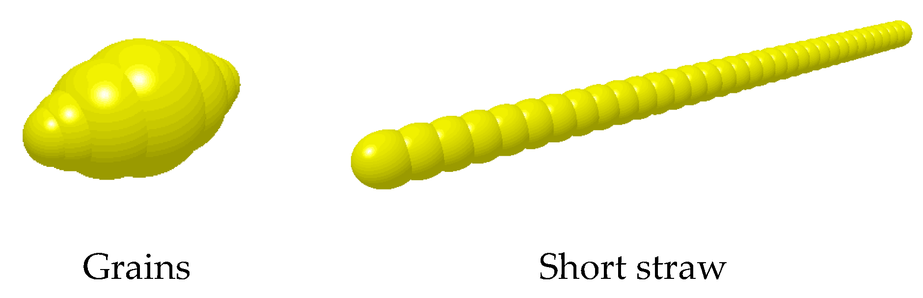
2.3. Discrete Element Simulation Test
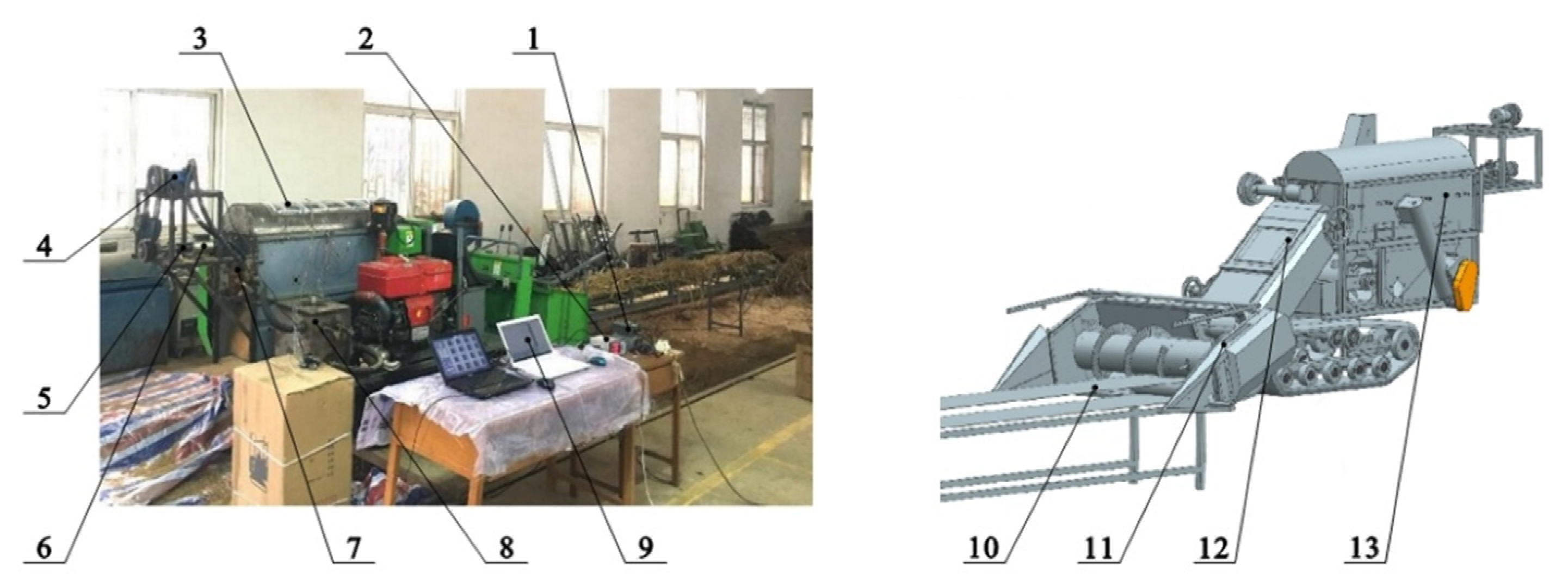
It is an important method to analyze the threshing performance of the cylinder to study the movement pattern and force condition of grain mixture in threshing and separating device. However, its movement and force in threshing and separating device are complex, which makes it difficult to analyze by traditional theory or experimental research. Fortunately, the continuous development of discrete element method and the application of EDEM software provide a new choice for simulating the movement of grain mixture in the threshing and separating device.
The mixture from threshing and separating device includes grain, short straw, glume, light debris, etc. However, its main components are grain and short straw, which takes up 95% of the mixture mass [19,20,21]. In order to simplify the types of particle models and improve the simulation efficiency, only the effects of grain and short straw were considered in the simulation process. The rice grain was simplified as an ellipsoid of homogeneous linear elastic material, with the length of 6.5 mm and the diameter of the largest section circle in the length direction of 3.5 mm. According to the actual size of the short straw in the mixture, the rice grain was simplified as a cylinder composed of 34 spherical particles with a diameter of 4 mm and a length of 70 mm, as shown in Figure 4.
The physical parameters of the rice grain, short straw, and threshing device are shown in Table 1 [22].
The contact model is an important basis of the discrete element method. The analysis and calculation of the contact model directly determine the magnitude of the force and moment on the particle. In this paper, the Hertz–Mindlin non-sliding contact model was used to analyze the contact between the material and threshing device [23,24,25]. The contact stiffness of this model varied with the contact overlap of particles, and it was a nonlinear model. The contact parameters between materials and materials and between materials and threshing device are shown in Table 2 [22].
Two pellet factories were set up at the feeding entrance cylinder, namely rice grain pellet factory and short straw pellet factory. Since the mass of the short straw among the threshed mixture processed by full feeding longitudinal axial flow threshing and separating device took up 30% of the total mass [19], the feeding rate was set to be 1.2 kg/s (the rate of rice grain production was 0.84 kg/s, the rate of rice straw production was 0.36 kg/s), the particle generation time was 2 s, and the total simulation time was 5 s. According to the actual situation where the particles were produced at the feeding inlet of the threshing and separating device, the initial speed was set as 2.8 m/s according to the conveying speed of the intermediate conveying device of the combine harvester. The threshing cylinder was set to be working in the simulation with a speed of 1100 r/min. The calculation time step was set as 10% of Rayleigh time step and the output time step as 0.01 s.
The total length of the designed threshing cylinder was 1360 mm, in which the feeding section is 190 mm, the outlet section was 170 mm, the threshing and separating section was 1000 mm, and the width of the plates on both sides of the threshing cylinder was 500 mm. The threshing and separating device were divided into 10 areas along the axial direction and 5 areas along the radial direction, with a total of 10 areas × 5 = 50 areas, each of whose size was 100 mm × 100 mm, as shown in Figure 5.
In order to explain the axial and radial distribution of the threshed mixture, the statistical fields in Figure 5 are numbered as shown in Figure 6.
The numbers of each area are shown in Table 3.

2.4. Bench Test

The performance test platform of small longitudinal axial flow threshing and separating device designed in this paper was modified from the small longitudinal axial flow combine harvester “4LZ-1.6” produced by Hunan Nongyou Machinery Group Co., Ltd., and its structure is shown in Figure 7.
The total length of the conveyor belt is 6.0 m, and the head end is 1.0 m free. Firstly, 6 kg rice straw was evenly laid at 5.0 m behind the conveyor belt, so that the conveyor belt could feed rice after obtaining a stable transmission speed to ensure accurate and uniform feeding [26,27]. When the frequency of the frequency converter was adjusted to make the belt speed 1.0 m/s, the designed feeding amount of the threshing cylinder is 1.2 kg/s, which was consistent with the feeding amount of the simulation test. The experiment was repeated three times.
In each test, the threshing cylinder was started to rotate through the hydraulic valve. When the rotation was stable, the transmission of header feeding auger and conveying channel was started through the clutch. Finally, the transmission of conveyor belt was started through the frequency converter. The material receiving device under the concave screen collected the threshed mixture, and the oil cloth was used under the straw outlet to collect the discharged mixture. After feeding, the transmission of conveyor belt was stopped first, and then the transmission of header auger and conveying channel were stopped. When all the rice straw in the cylinder was discharged from the straw outlet, the transmission of threshing cylinder was stopped. Refer to the above test evaluation index for the treatment method of prolapse, and finally take the average value of three tests for the mass of threshed mixture in each area. After stopping the machine, we took out the material receiving device, collected the threshed mixture in each small box respectively, and weighed it with a BT457 electronic balance produced by Suzhou Shunqiang Electromechanical Equipment Co., Ltd., with an accuracy of 0.1 g. A total of three tests were conducted to obtain the average value of the mass of the mixture in each area.
The experiment was conducted in the Electromechanical Training Center of Huazhong Agricultural University. The rice variety was Huanghuazhan. The average plant height was 1076.50 mm. The rice was manually harvested, the stubble was 200–300 mm, the rice length was 876.50–776.50 mm, the 1000 grain weight was 28.25 g, the moisture content of grain was 22.35%, and the moisture content of straw was 68.31%. The rice was planted in the rice experimental base of Huazhong Agricultural University.

3. Results and Discussion

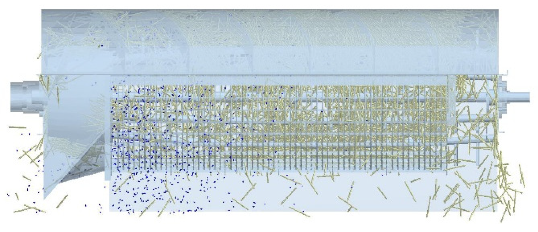
3.1. Simulation Process Analysis

The whole process of threshing and separating of threshed mixture in the cylinder could be simulated by software simulation. The threshing simulation model is shown in Figure 8. The mixed material enters the threshing cylinder under the action of the spiral feeding head. Under the action of threshing teeth and guide plate, the mixed material flows forward along the spiral of the inner arc surface composed of concave plate and top cover, and then it is discharged from the straw outlet. During this period, a large number of rice grains are rapidly threshed and separated in the front part of the cylinder under the action of centrifugal force generated by the high-speed rotation of the cylinder.

3.2. Simulation Results and Analysis

The distribution of the threshed mixture in the statistical domain is shown in Figure 9 and Figure 10. Axial zone 1 refers to 1-1 to 1-10 in Table 3, and there are 5 zones in the axial direction; radial region 1 refers to 1-1 to 5-1 in Table 3, and there are 10 radial regions. Considering that the subsequent distribution of the threshed mixture is relatively small, the radial distribution of the threshed mixture is analyzed in the radial 1–5 region.
It can be seen from Figure 9 that for any radial region, the mass of the threshed mixture decreases gradually along the axial direction of the cylinder, and mainly distributes in the first 1/3 section of the cylinder. Axial zone 1 and axial zone 5 correspond to the left and right sides of the threshing cylinder respectively, and the total mass of the threshed mixture is higher than that of the middle zone.
Figure 10 indicates that for any radial region, the mass of the threshed mixture along the axial region of the cylinder decreases gradually at first and then increases. The mass of the threshed mixture in the radial region 5 is always higher than that in the region 1. The results also show that the spike tooth reaction force and bar tooth impact force of threshing device are complex periodic functions of angular displacement of grain motion [28,29,30]. Because of the rotation direction of the threshing cylinder, the “compaction area” is formed between the threshing cylinder and the right side of the concave screen. In this area, the difference between the linear speed of the material and the threshing cylinder is large, and the impact force of the rod teeth is large.
In order to observe the axial and radial variation trend of the threshed mixture along the cylinder more comprehensively, the three-dimensional distribution of the mass of threshed mixture is drawn by using MATLAB software, as shown in Figure 11.
It can be seen from Figure 11 that the distribution of the threshed mixture along the axial and radial direction of the cylinder is uneven. Its mass distribution is like a “skateboard”, which is high on both sides, low in the middle, steep in the front, and flat in the back.

3.3. Bench Test Results and Analysis

The threshed mixture from the drum-shape threshing cylinder is shown in Figure 12.
We weighed the mixture of each small box in Figure 12, and obtained the change pattern of the mass of the mixture along the axial and radial direction of the cylinder, as shown in Figure 13 and Figure 14. According to the simulation test method, the mixture was divided into 1~5 zones along the radial direction, and the 1~5 zones near the feeding end in axial direction were taken for the experimental analysis.
It can be seen from Figure 13 that along the axial direction of the cylinder, the mass of the mixture in zone 1~4 decreases gradually from the feeding inlet to the straw discharge outlet, and the maximum peak value appears in zone 5–2. Among the five radial regions, the axial region 5 had the highest mass of the mixture, followed by region 1. In addition, the mass of the mixture is mainly concentrated in the first half of the threshing cylinder. This result was basically consistent with the simulation test, but the radial zone 5 appeared the maximum value in the axial zone 2 in the bench test, which may be caused by the uneven initial moment when the material enters the cylinder. In the simulation test, there was basically no threshed mixture after axial zone 6, while in the bench test, there was still some mixture left after axial zone 6. This is because the materials set in the simulation test were only grains and short straw, while in the actual work, there were also leaves, ear heads and branches, etc. Although these parts account for less mass, they will affect the collision between particles, thus affecting the separating effect.
According to Figure 14, the mass of the mixture in axial 1–5 region decreases first and then increases along the radial direction of the cylinder. For the same radial region, the mass of the mixture in region 5 is always higher than that in region 1, which is consistent with the simulation results. It indicates that it is feasible to use the EDEM software to simulate the distribution pattern of the threshed mixture from the longitudinal axial flow threshing and separating device. However, as the simulation parameters in this paper all refer to the existing research settings, there may be some deviation from the physical parameters of the actual test materials, thus affecting the test effect. In a future study, the key parameters in the simulation process can be further calibrated to make it more accurate.

4. Conclusions

(1)
In this paper, a drum-shape bar-tooth longitudinal axial flow threshing and separating device was designed, and its working principle was studied.
(2)
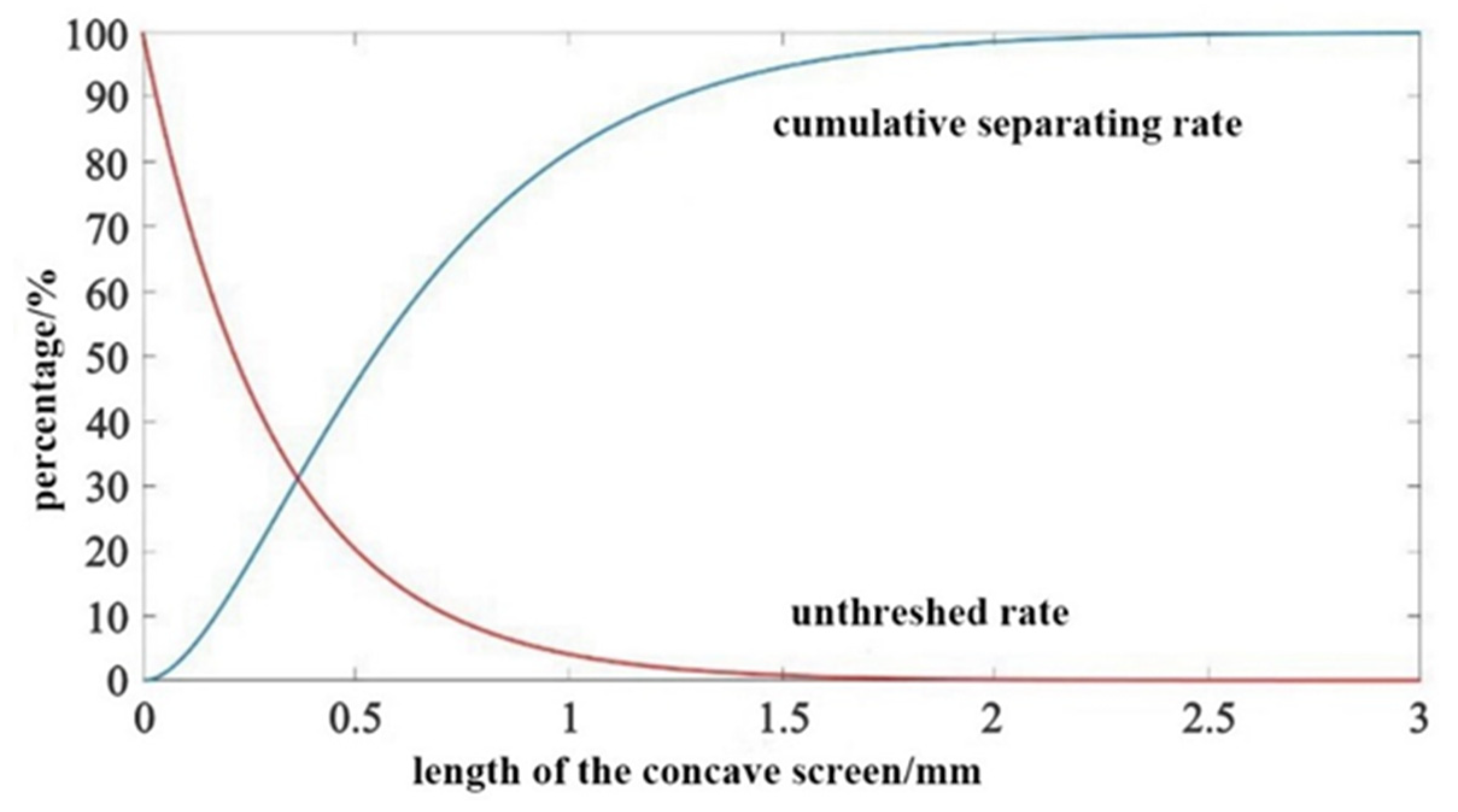
Based on the probability theory, the threshing and separating model was established, and the threshing and separating characteristic curve of the drum-shape bar-tooth longitudinal axial flow threshing cylinder was obtained. According to the curve, threshing and separating basically occur in the first half of the threshing cylinder.
(3)
The length of the cylinder could be selected according to the distribution pattern of the axial threshed mixture. On the premise of meeting the threshing performance, the length of the threshing cylinder should be as short as possible.
(4)
The distribution of the threshed mixture along the axial region of the cylinder was gradually decreasing, and mainly distributed in the first one-third section of the cylinder. The mass of the threshed mixture along the radial region of the cylinder decreases gradually at first and then increases, and the total mass of threshed mixture on the left and right sides was higher than that in the middle area. The bench test results were basically consistent with the simulation results. This study can provide a reference for optimizing the structure parameters of the threshing and separating device and cleaning system.

5. Patents

Two patents have been applied in China for a drum-shape bar-tooth threshing cylinder for combine harvester in this manuscript (Patent No. CN201921966457.2 and Application No. CN201911113778.2).

Author Contributions

Conceptualization, J.F., Y.Z. and G.X.; methodology, J.F. and G.X.; software, J.F., G.X. and C.J.; validation, J.F., Y.Z., C.J., G.X., W.W., G.Z., X.Z. and M.A.A.; formal analysis, J.F.; investigation, J.F., C.J., G.X., W.W., X.Z. and M.A.A.; resources, J.F.; data curation, J.F.; writing—original draft preparation, J.F.; writing—review and editing, J.F.; visualization, J.F.; supervision, Y.Z.; project administration, G.Z.; funding acquisition, G.Z. All authors have read and agreed to the published version of the manuscript.

Funding

This work was financially supported by the Project of Scientific and Technological Innovation Team for the Excellent Young and Middle-aged in Hubei Province (T201934), the Fundamental Research Funds for the Central Universities (2662018PY038) and the National Key Research and Development Program of China (Technological Innovation of Regenerated Rice Mechanization in the North of the Middle and Lower Reaches of the Yangtze River, 2017YFD0301404-05).

Institutional Review Board Statement

Not applicable.

Data Availability Statement

The data presented in this study are available on demand from the first author at (fjwtap@mail.hzau.edu.cn).

Conflicts of Interest

The authors declare no conflict of interest.

References

  1. Li, Y.M. Study on Separation of Rethreshed Stripped Mixtures and Their Cleaning Characteristics for Rice. Ph.D. Thesis, Nanjing Agricultural University, Nanjing, China, 2004. [Google Scholar]
  2. Miu, P.; Kutzbach, H. Mathematical model of material kinematics in an axial threshing unit. Comput. Electron. Agric. 2007, 58, 93–99. [Google Scholar] [CrossRef]
  3. Li, J.; Yan, C.L.; Yang, F.F. Theoretical model and simulation of threshing of axial unit with axial feeding. J. Jiangsu Univ. 2006, 4, 299–302. [Google Scholar]
  4. Zhang, Y.F.; Lai, Y.J.; Zhang, K.; Sun, J.J. Research on The Axial Direction Distribution Regularities of Emerging Object with Axial Flow Threshing Installation. J. Heilongjiang August First Land Reclam. Univ. 2006, 5, 34–36. [Google Scholar]
  5. Zhang, W.; Yi, S.J. The Establishment and Simulation of Mathematical Model on the Axial Threshing and Separating Unit. J. Agric. Mech. Res. 2007, 7, 40–42+47. [Google Scholar]
  6. Yi, S.J.; Tao, G.X.; Mao, X. Comparative experiment on the distribution regularities of threshed mixtures for two types of axial flow threshing and separating installation. Trans. CSAE 2008, 6, 154–156. [Google Scholar]
  7. Tao, G.X.; Yi, S.J. Distribution of mixture assembled axial flow device. J. Agric. Mech. Res. 2009, 31, 134–136+140. [Google Scholar]
  8. Li, Y.M.; Li, H.C.; Xu, L.Z. Comparative experiments on threshing performance between short-rasp-bar tooth cylinder and spike tooth cylinder. Trans. CSAE 2008, 3, 139–142. [Google Scholar]
  9. Li, Y.M.; Li, H.C.; Xu, L.Z.; Zhao, Z. Performance Test of Short-rasp-bar of Axial Flow Threshing and Separating Unit. Trans. Chin. Soc. Agric. Mach. 2009, 40, 88–92. [Google Scholar]
  10. Guo, Y.; Li, Y.M.; Li, H.C.; Xu, L.Z. The Radial Distribution Regularities of Emerging Object with Longitudinal Axial Flow Threshing and Separating Device. J. Agric. Mech. Res. 2011, 33, 110–112. [Google Scholar]
  11. Tang, Z.; Li, Y.M.; Xu, L.Z.; Zhao, Z.; Li, H.C. Effects of different threshing components on grain threshing and separating by tangential-axial test device. Trans. CSAE 2011, 27, 93–97. [Google Scholar]
  12. Chen, N.; Yu, H.J.; Chen, D.J.; Gong, Y.J.; Zhang, Z.Z. Design and Test on Coaxial Differential Threshing Rotor of Head-feed Combine Harvester. Trans. Chin. Soc. Agric. Mach. 2011, 42, 39–42. [Google Scholar]
  13. Chen, Y.P.; Kang, Y.; Wang, T.E.; Ning, X.J.; Jin, C.Q.; Yin, X. Distribution regularities of the threshed mixtures in longitudinal axial flow flexible thresher of soybean harvester. J. China Agric. Univ. 2020, 25, 104–111. [Google Scholar]
  14. Xie, G.; Zhang, G.Z.; Fu, J.W.; Zhou, Y.; Wang, Y.; Gao, Y.; Wang, W.K.; Mohamed, A. Comparing power consumption of drum and cylindrical bar-tooth longitudinal axial flow threshing roller. J. Huazhong Agric. Univ. 2021, 40, 202–209. [Google Scholar]
  15. Xie, G. Design and Experimental Research of Drum-Shape Bar-Tooth Longitudinal Axial Flow Threshing and Separating Device. Master’s Thesis, Huazhong Agricultural University, Wuhan, China, 2020. [Google Scholar]
  16. Abdeen, M.A.; Salem, A.E.; Zhang, G.Z. Longitudinal Axial Flow Rice Thresher Performance Optimization Using the Taguchi Technique. Agriculture 2021, 11, 88. [Google Scholar] [CrossRef]
  17. Xu, L.Z. Simulation and Test Research on Threshing Unit of Stripping Combine. Master’s Thesis, Jiangsu University, Zhenjiang, China, 2003. [Google Scholar]
  18. Wang, X.W.; Xie, F.P.; Ren, S.G.; Wang, X.S.; Zhang, Z.Z. A mathematical model and test of the horizontal axial flow threshing separation device. J. Hunan Agric. Univ. 2020, 46, 480–487. [Google Scholar]
  19. Lu, K. Design and Performance Experiment of a Small Horizontal-Axial Threshing and Separating Device for Ratoon Rice. Master’s Thesis, Huazhong Agricultural University, Wuhan, China, 2017. [Google Scholar]
  20. Zhao, S.H.; Zhang, G.Z.; Zhang, S.J.; Fu, J.W.; Xie, G.; Mohamed, A. Designing a real-time feed measurement system for horizontal axial flow threshing drum based on thin film sensor. J. Huazhong Agric. Univ. 2020, 39, 160–169. [Google Scholar]
  21. Zhao, S.H. Design of Measurement System for Horizontal Axial Flow Threshing Drum Based on Film Sensors. Master’s Thesis, Huazhong Agricultural University, Wuhan, China, 2019. [Google Scholar]
  22. Wang, D.Z. Simulation Analysis and Threshing Performance of Horizontal-Axial Threshing Device. Master’s Thesis, University of Jinan, Jinan, China, 2018. [Google Scholar]
  23. Zha, X.T.; Zhang, G.Z.; Han, Y.H.; Salem, A.E.; Fu, J.W.; Zhou, Y. Structural Optimization and Performance Evaluation of Blocking Wheel-Type Screw Fertilizer Distributor. Agriculture 2021, 11, 248. [Google Scholar] [CrossRef]
  24. Wang, W.Z.; Liu, W.R.; Yuan, L.H.; Qu, Z.; He, X.; Lv, Y.L. Simulation and Experiment of Single Longitudinal Axial Material Movement and Establishment of Wheat Plants Model. Trans. Chin. Soc. Agric. Mach. 2020, 51, 170–180. [Google Scholar]
  25. Su, Z.; Li, Y.M.; Dong, Y.H.; Tang, Z.; Liang, Z.W. Simulation of rice threshing performance with concentric and non-concentric threshing gaps. Biosyst. Eng. 2020, 197, 270–284. [Google Scholar] [CrossRef]
  26. Fu, J.W.; Zhang, G.Z.; Xie, G.; Wang, Y.; Gao, Y.; Zhou, Y. Development of double-channel feeding harvester for ratoon rice. Trans. Chin. Soc. Agric. Eng. 2020, 36, 11–20. [Google Scholar]
  27. Fu, J.W. Development of Double-Channel Full Feeding Harvester for Ratoon Rice. Ph.D. Thesis, Huazhong Agricultural University, Wuhan, China, 2020. [Google Scholar]
  28. Zhang, R.C.; Sang, Z.Z. Dynamic Simulation of the Axial Threshing Process of Combine Harvesters. Trans. Chin. Soc. Agric. Mach. 2001, 47, 58–60. [Google Scholar]
  29. Tian, L.Q.; Li, H.Y.; Hu, H.D.; Chen, L.B.; Xiong, Y.S.; Jin, R.D. Design and Experiment on Coaxial Double Speed Threshing for Combine Harvester. Trans. Chin. Soc. Agric. Mach. 2020, 51, 139–146. [Google Scholar]
  30. Huang, X.N. Design and Experimental Research on Tangential and Transverse Axial Flow Threshing System of Windrow Harvesting for Buckwheat. Master’s Thesis, Northwest A&F University, Xianyang, China, 2020. [Google Scholar]
Figure 1. Structure diagram of drum-shape bar-tooth longitudinal axial-flow threshing and separating device.
Agriculture 11 00756 g001
Figure 2. Structure of the drum-shape bar-tooth longitudinal axial flow threshing cylinder. 1. Shaft head; 2. Trailer wheel; 3. Drum-shape bar-tooth; 4. Threshing teeth; 5. Bar-tooth mounting plate; 6. Spiral blade; 7. Front flange; 8. Front disc; 9. Conical cylinder; 10. Rear disc; 11. Shaft tube; 12. Middle wheel; 13. Rear flange.
Agriculture 11 00756 g002
Figure 3. The axial distribution curve of the unthreshed rate of grain and the cumulative separating rate of threshed grain along the concave screen.
Agriculture 11 00756 g003
Figure 4. Model of rice grain and short straw.
Agriculture 11 00756 g004
Figure 5. Regional distribution of statistical domain.
Agriculture 11 00756 g005
Figure 6. Regional distribution of the threshing and separating device along the axial and radial directions.
Agriculture 11 00756 g006
Figure 7. Performance test platform of longitudinal axial flow threshing and separating device. 1. Frequency converter; 2. Torque speed power tester; 3. Acrylic board; 4. Hydraulic motor; 5. Elastic coupling; 6. Torque sensor; 7. Hydraulic control valve; 8. Hydraulic tank; 9. Computer; 10. Conveyor belt; 11. Header; 12. Conveying channel; 13. Threshing and separating device.
Agriculture 11 00756 g007
Figure 8. Simulation model of threshing.
Agriculture 11 00756 g008
Figure 9. Axial distribution of the mixture separated by the drum-shape cylinder.
Agriculture 11 00756 g009
Figure 10. Radial distribution of the mixture separated by the drum-shape cylinder.
Agriculture 11 00756 g010
Figure 11. Grain distribution diagram in each area of the vertical axial-flow threshing cylinder.
Agriculture 11 00756 g011
Figure 12. Physical picture of mixture distribution.
Agriculture 11 00756 g012
Figure 13. Axial distribution of the mixture separated by the drum-shape cylinder.
Agriculture 11 00756 g013
Figure 14. Radial distribution of the mixture separated by the drum-shape cylinder.
Agriculture 11 00756 g014
Table 1. Mechanical characteristic parameters of materials and threshing device.
ModelPoisson’s RatioShear Modulus (MPa)Density (kg/m3)
Grains0.3261350
Short straw0.410100
Threshing device0.370,0007800
Table 2. Interaction parameters of materials and threshing device.
Contact ObjectCoefficient
of Restitution
Coefficient of Static FrictionCoefficient of Rolling Friction
Between grains and grains0.21.00.01
Between grains and short straw0.20.80.01
Between grains and Threshing device0.50.580.01
Between short straw and short straw0.20.90.01
Between short straw and Threshing device0.20.80.01
Table 3. Area distribution of threshing and separating performance test.
Axial
radial1-11-21-31-41-51-61-71-81-91-10
2-12-22-32-42-52-62-72-82-92-10
3-13-23-33-43-53-63-73-83-93-10
4-14-24-34-44-54-64-74-84-94-10
5-15-25-35-45-55-65-75-85-95-10
Publisher’s Note: MDPI stays neutral with regard to jurisdictional claims in published maps and institutional affiliations.

