
Imaging in Hip Arthroplasty Management—Part 1: Templating: Past, Present and Future
 , and
, and
Abstract
:1. Introduction
2. Preoperative Planning
2.1. Background
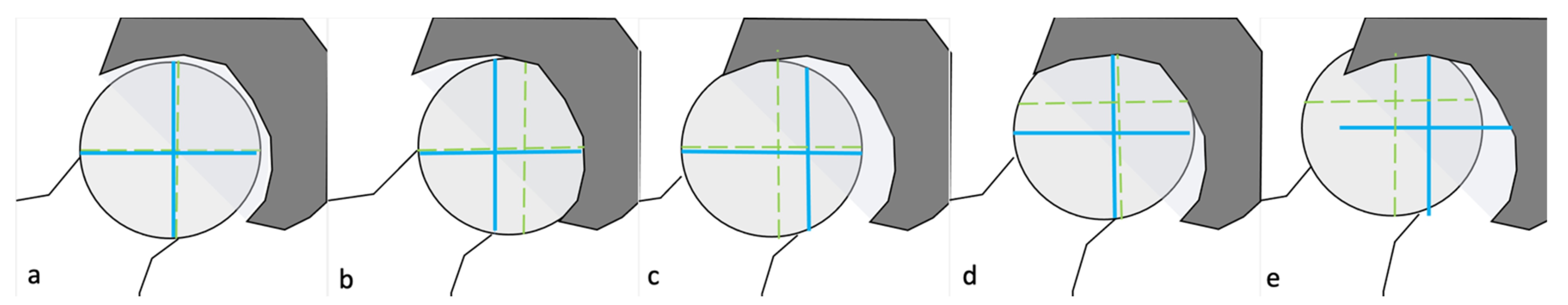
2.2. Hip Deformities
2.2.1. Measurements and Their Implications
2.2.2. Types of Architectural Deformities and Their Implications
2.3. Principles and Methods
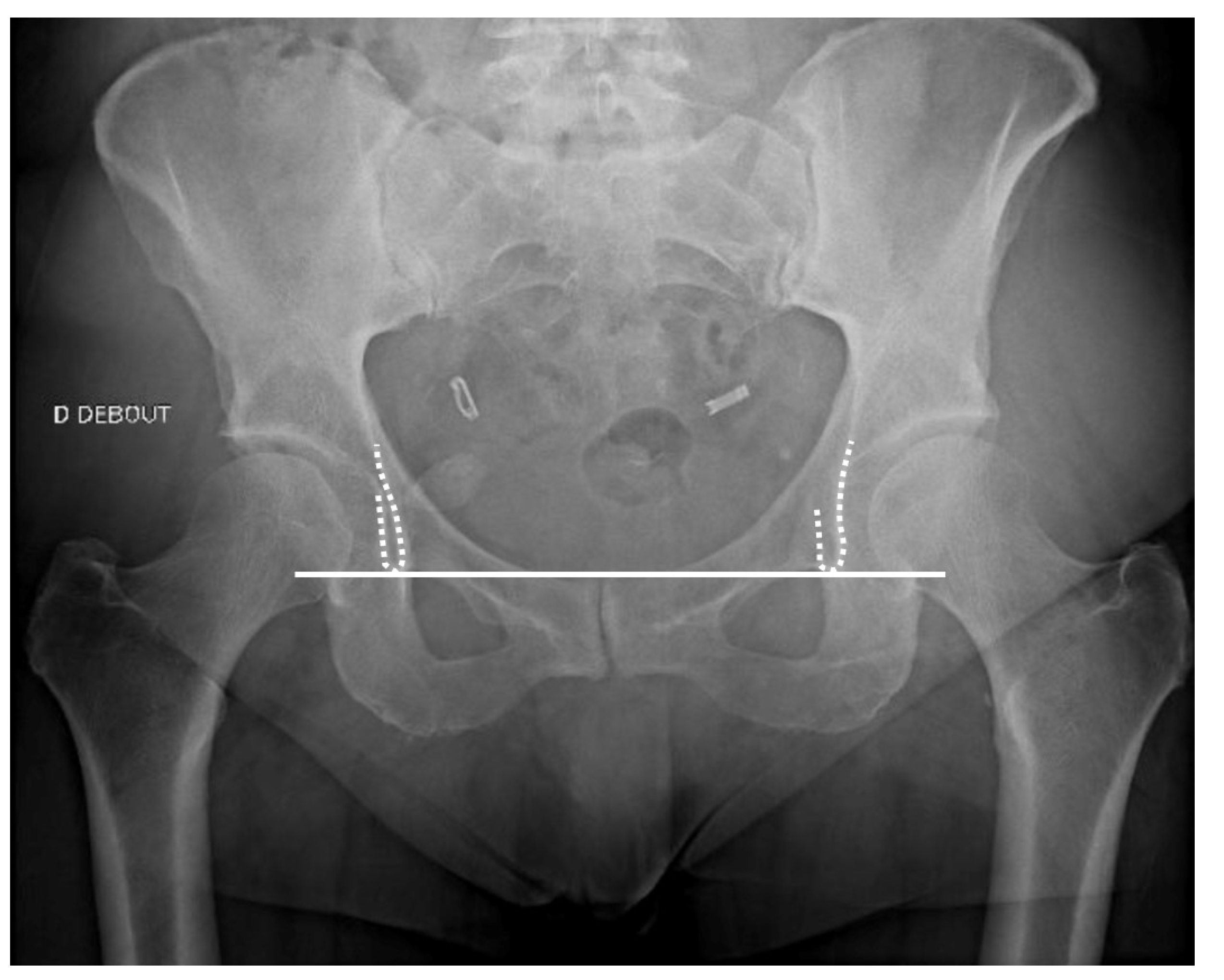
2.3.1. Radiographs Technical Aspects
Acetabular Cup Templating
Femoral Stem Templating
2.4. Perspectives
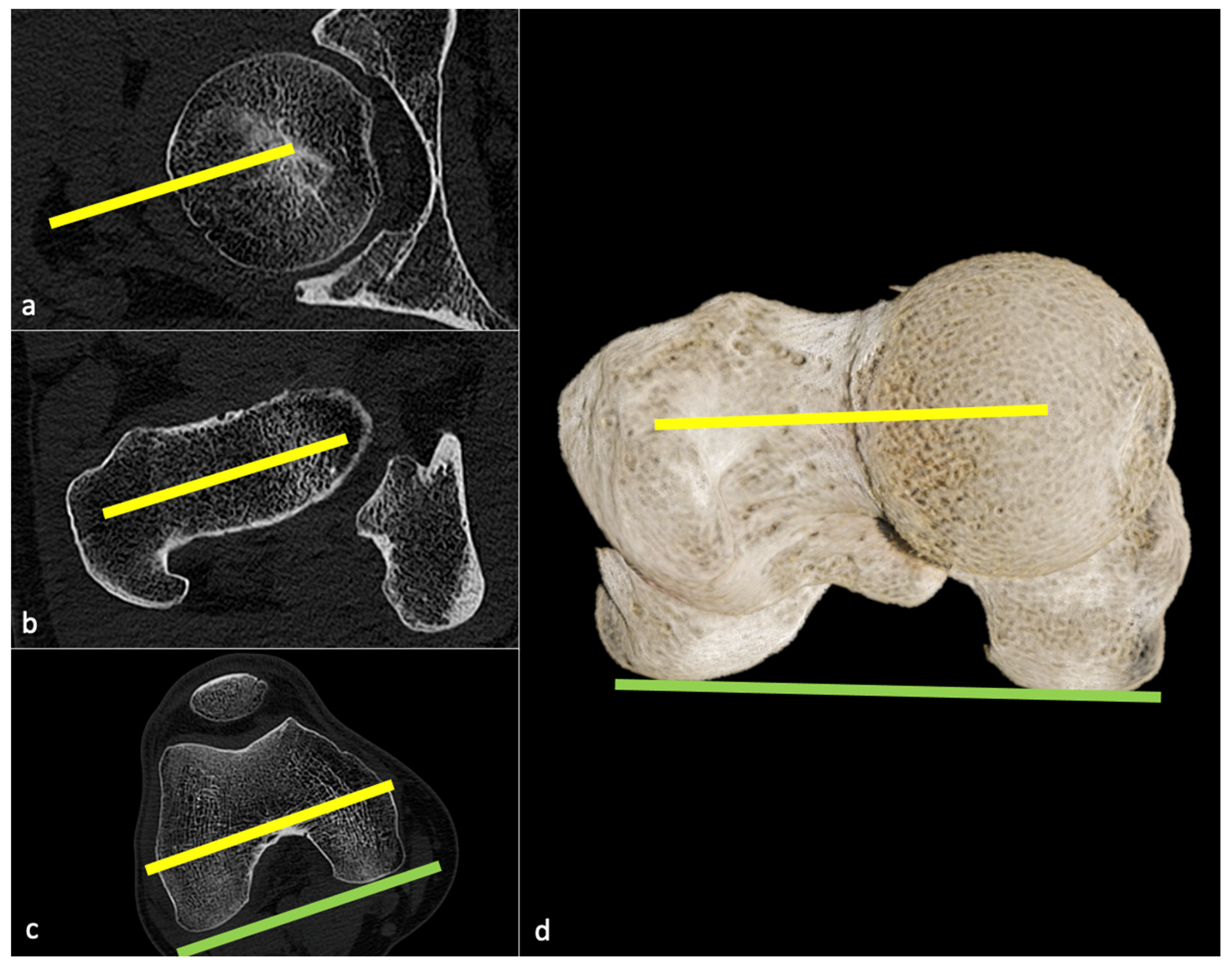
2.4.1. CT-Scan
Background
Technical Aspect
- (1)
- the hip can be classified as mentioned above (e.g., centered, medialized, lateralized, proximalized, or proximo-lateralized);
- (2)
- the pre-arthritic centers of the femoral head and acetabulum must be determined (potentially using the contralateral hip if healthy), and the optimal diameter of the acetabular cup measured on a transverse CT slice, so that its template can be positioned at the level of the true acetabular floor medially and of the subchondral bone proximally, slightly superior and medial to the center of the native acetabulum to simulate reaming;
- (3)
- the stem size and model can be determined, such that the templated head center can match the templated cup center craniocaudally, with the native mediolateral center maintained original even if pathologic, except in case of medialized head, which has to match templated cup center in both axis [60].
Main Strengths
Limitations
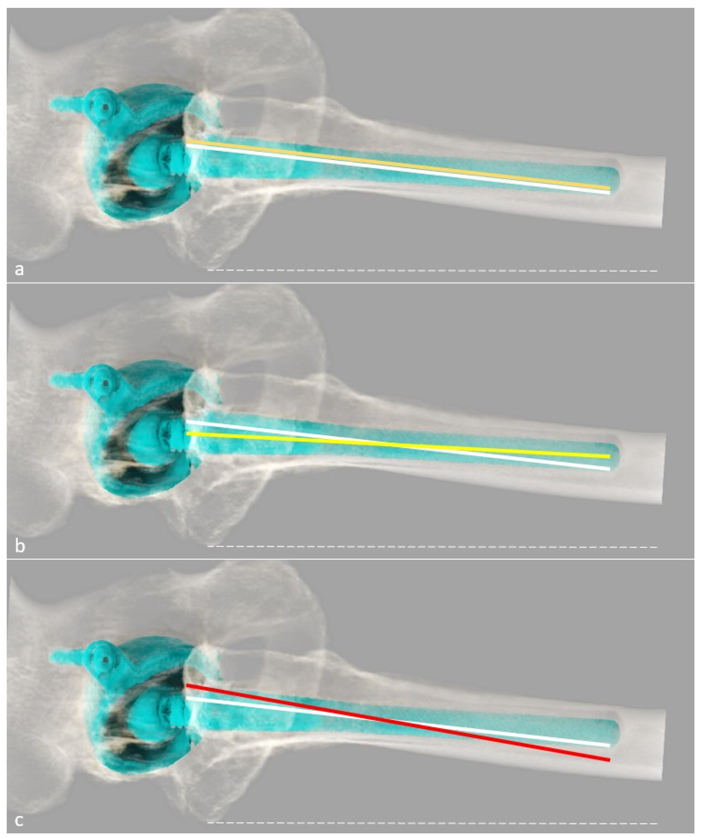
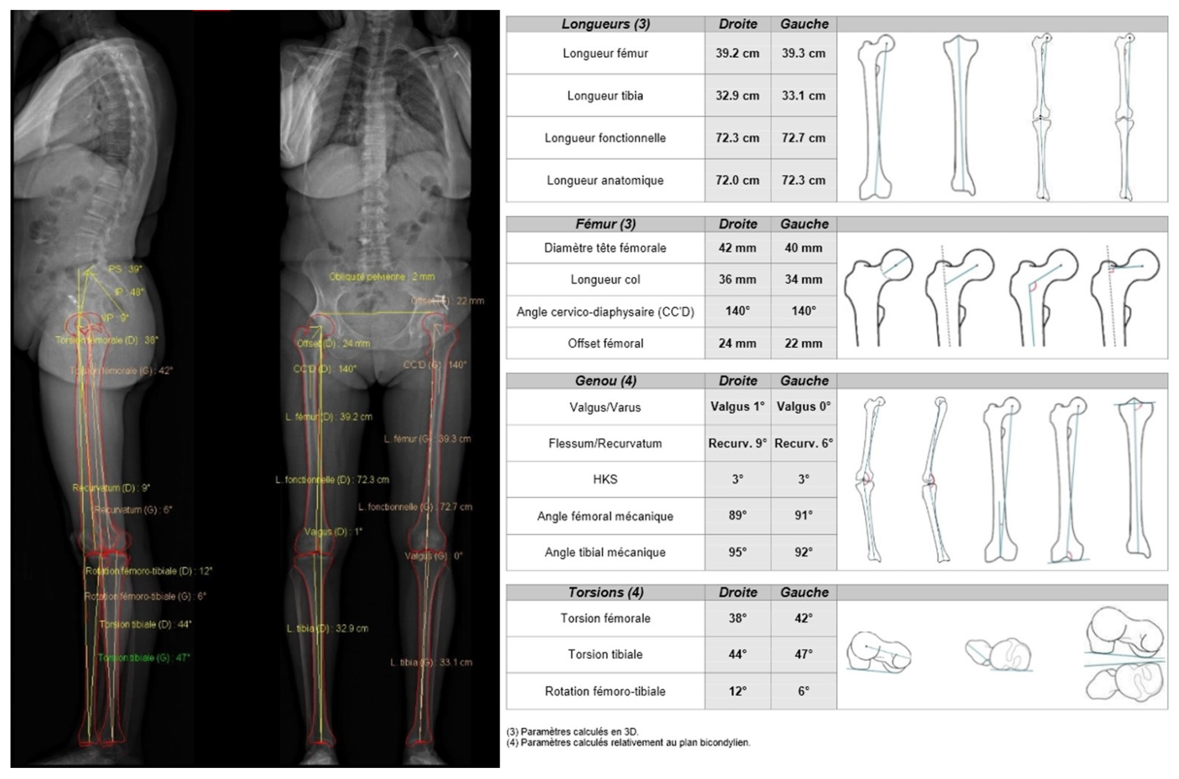
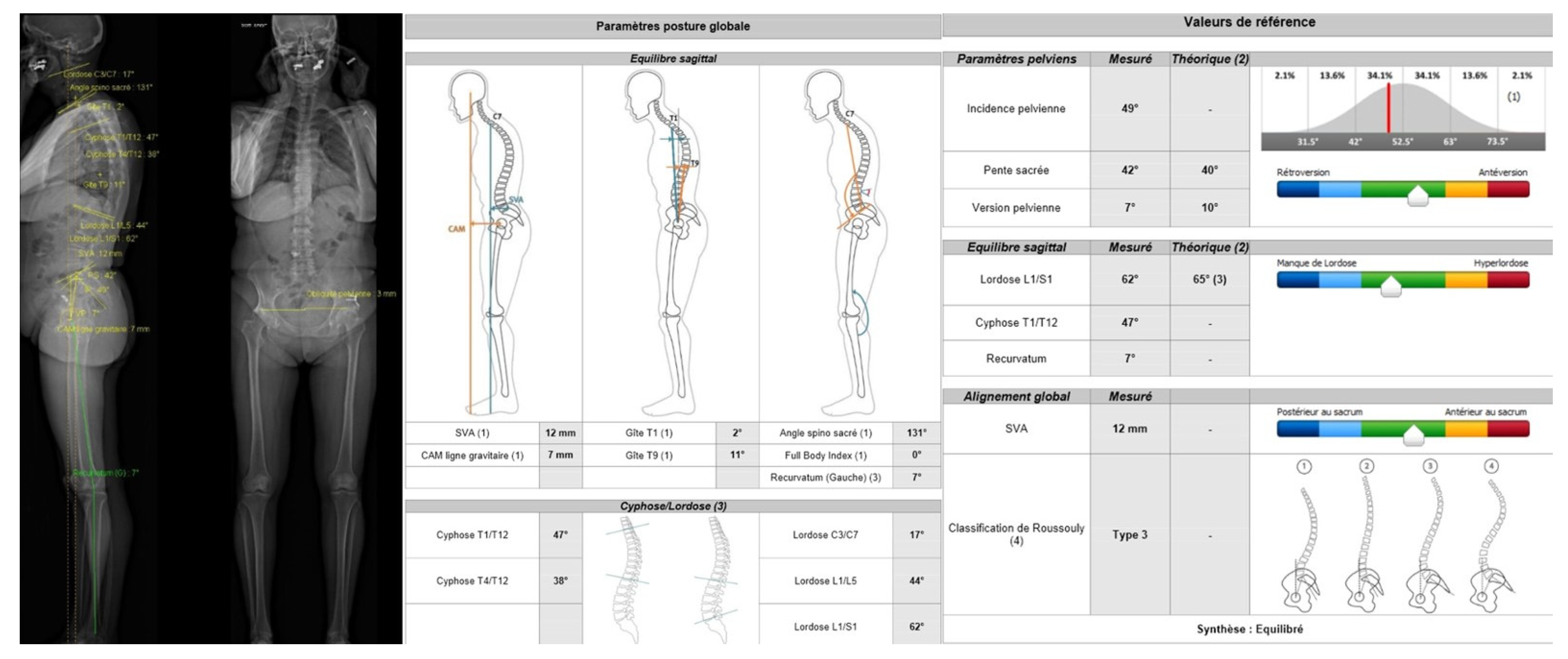
2.4.2. EOS® Imaging
Background
Practical Aspect
Main Strengths
Limitations
Rationale for Preoperative Planning
3. Conclusions
Author Contributions
Funding
Institutional Review Board Statement
Informed Consent Statement
Data Availability Statement
Conflicts of Interest
Abbreviations
| AO | acetabular offset |
| AP | anteroposterior |
| CDA | cervico-diaphyseal angle |
| CT | computed tomography |
| FNA | femoral neck antetorsion |
| FO | femoral offset |
| GO | global offset |
| HA | hip arthroplasty |
| PE | polyethylene |
| THA | total hip arthroplasty |
References
- Gillet, R.; Teixeira, P.; Bonarelli, C.; Coudane, H.; Sirveaux, F.; Louis, M.; Blum, A. Comparison of Radiographs, Tomosynthesis and CT with Metal Artifact Reduction for the Detection of Hip Prosthetic Loosening. Eur. Radiol. 2019, 29, 1258–1266. [Google Scholar] [CrossRef] [PubMed]
- Knafo, Y.; Houfani, F.; Zaharia, B.; Egrise, F.; Clerc-Urmès, I.; Mainard, D. Value of 3D Preoperative Planning for Primary Total Hip Arthroplasty Based on Biplanar Weightbearing Radiographs. BioMed Res. Int. 2019, 2019, 1932191. [Google Scholar] [CrossRef] [PubMed]
- Cech, A.; Kase, M.; Kobayashi, H.; Pagenstert, G.; Carrillon, Y.; O’Loughlin, P.F.; Aït-Si-Selmi, T.; Bothorel, H.; Bonnin, M.P. Pre-Operative Planning in THA. Part III: Do Implant Size Prediction and Offset Restoration Influence Functional Outcomes after THA? Arch. Orthop. Trauma Surg. 2020, 140, 563–573. [Google Scholar] [CrossRef] [PubMed]
- Chinzei, N.; Noda, M.; Nashiki, H.; Matsushita, T.; Inui, A.; Hayashi, S. Conventional Computed Tomography Software Can Be Used for Accurate Pre-Operative Templating in Bipolar Hip Arthroplasty: A Preliminary Report. J. Clin. Orthop. Trauma 2021, 13, 1–8. [Google Scholar] [CrossRef] [PubMed]
- Huang, J.; Zhu, Y.; Ma, W.; Zhang, Z.; Shi, W.; Lin, J. A Novel Method for Accurate Preoperative Templating for Total Hip Arthroplasty Using a Biplanar Digital Radiographic (EOS) System. JBJS Open Access 2020, 5, e20.00078. [Google Scholar] [CrossRef] [PubMed]
- Inoue, D.; Kabata, T.; Maeda, T.; Kajino, Y.; Fujita, K.; Hasegawa, K.; Yamamoto, T.; Tsuchiya, H. Value of Computed Tomography-Based Three-Dimensional Surgical Preoperative Planning Software in Total Hip Arthroplasty with Developmental Dysplasia of the Hip. J. Orthop. Sci. 2015, 20, 340–346. [Google Scholar] [CrossRef] [PubMed]
- Mishra, A.; Verma, T.; Rajkumar; Agarwal, G.; Sharma, A.; Maini, L. 3D Printed Patient-Specific Acetabular Jig for Cup Placement in Total Hip Arthroplasty. JOIO 2020, 54, 174–180. [Google Scholar] [CrossRef]
- Nishihara, S.; Hayashida, K. Comparison between Freehand Technique and Computed Tomography-Based Navigation in Acetabular Cup Placement through Direct Anterior Approach for Total Hip Arthroplasty. Arch. Orthop. Trauma Surg. 2021, 142, 323–329. [Google Scholar] [CrossRef] [PubMed]
- Scheerlinck, T.; De Winter, E.; Sas, A.; Kolk, S.; Van Gompel, G.; Vandemeulebroucke, J. Hip Implants Can Restore Anatomical and Medialized Rotation Centres in Most Cases: A 3D Templating Study Comparing Four Implantation Strategies. Bone Jt. Open 2021, 2, 476–485. [Google Scholar] [CrossRef] [PubMed]
- Thurston, D.; El-Ashry, S.; Gella, S.; Theivendran, K. Digital Templating in Hip Hemiarthroplasty: Is It Possible to Accurately Predict Femoral Head Size from Magnification Alone? J. Clin. Orthop. Trauma 2022, 32, 101952. [Google Scholar] [CrossRef]
- Ma, S.; Xiao, L.; Guo, D.; Shi, Q.; Shen, R.; Li, X. Application of 3D-Printed Osteotomy Guides in Periacetabular Osteotomy: A Short-Term Clinical Study. Int. J. Artif Organs 2022, 3913988221120026. [Google Scholar] [CrossRef] [PubMed]
- Morgan, S.; Barriga, J.; Dadia, S.; Merose, O.; Sternheim, A.; Snir, N. Three Dimensional Printing as an Aid for Pre-Operative Planning in Complex Cases of Total Joint Arthroplasty: A Case Series. J. Orthop. 2022, 34, 142–146. [Google Scholar] [CrossRef] [PubMed]
- Liu, F.; Tang, K.; Zheng, P.-F.; Zhang, Z.-Q.; Ling, G.; Lou, Y. Performance of Tönnis Triple Osteotomy in Older Children with Developmental Dysplasia of the Hip (DDH) Assisted by a 3D Printing Navigation Template. BMC Musculoskelet. Disord. 2022, 23, 712. [Google Scholar] [CrossRef] [PubMed]
- Bono, J.V. Digital Templating in Total Hip Arthroplasty. J. Bone Jt. Surg. Am. 2004, 86-A (Suppl. S2), 118–122. [Google Scholar] [CrossRef] [PubMed]
- Kase, M.; O’Loughlin, P.F.; Aït-Si-Selmi, T.; Pagenstert, G.; Langlois, J.; Bothorel, H.; Bonnin, M.P. Pre-Operative Templating in THA. Part I: A Classification of Architectural Hip Deformities. Arch. Orthop. Trauma Surg. 2020, 140, 129–137. [Google Scholar] [CrossRef] [PubMed]
- Geijer, M.; Kiernan, S.; Sundberg, M.; Flivik, G. Pre- and Postoperative Offset and Femoral Neck Version Measurements and Validation Using 3D Computed Tomography in Total Hip Arthroplasty. Acta Radiol. Open 2020, 9, 205846012096491. [Google Scholar] [CrossRef] [PubMed]
- Bhaskar, D.; Rajpura, A.; Board, T. Current Concepts in Acetabular Positioning in Total Hip Arthroplasty. Indian J. Orthop. 2017, 51, 386–396. [Google Scholar] [CrossRef] [PubMed]
- De Pieri, E.; Atzori, F.; Ferguson, S.J.; Dendorfer, S.; Leunig, M.; Aepli, M. Contact Force Path in Total Hip Arthroplasty: Effect of Cup Medialisation in a Whole-Body Simulation. HIP Int. 2021, 31, 624–631. [Google Scholar] [CrossRef] [PubMed]
- Zhao, R.; Cai, H.; Tian, H.; Zhang, K. Morphological Consistency of Bilateral Hip Joints in Adults Based on the X-Ray and CT Data. Surg. Radiol. Anat. 2021, 43, 1107–1115. [Google Scholar] [CrossRef]
- Pasquier, G.; Ducharne, G.; Sari Ali, E.; Giraud, F.; Mouttet, A.; Durante, E. Total Hip Arthroplasty Offset Measurement: Is C T Scan the Most Accurate Option? Orthop. Traumatol. Surg. Res. 2010, 96, 367–375. [Google Scholar] [CrossRef] [PubMed] [Green Version]
- Bjarnason, J.A.; Reikeras, O. Changes of Center of Rotation and Femoral Offset in Total Hip Arthroplasty. Ann. Transl. Med. 2015, 3, 355. [Google Scholar] [CrossRef] [PubMed]
- Yoshitani, J.; Kabata, T.; Kajino, Y.; Takagi, T.; Ohmori, T.; Ueno, T.; Ueoka, K.; Tsuchiya, H. The Effect of Flexion Alignment in Total Hip Arthroplasty with a Cementless Tapered-Wedge Femoral Stem. Eur. J. Orthop. Surg. Traumatol. 2018, 28, 1625–1632. [Google Scholar] [CrossRef]
- Abe, H.; Sakai, T.; Takao, M.; Nishii, T.; Nakamura, N.; Sugano, N. Difference in Stem Alignment Between the Direct Anterior Approach and the Posterolateral Approach in Total Hip Arthroplasty. J. Arthroplast. 2015, 30, 1761–1766. [Google Scholar] [CrossRef] [PubMed]
- Bonnin, M.P.; Archbold, P.H.A.; Basiglini, L.; Fessy, M.H.; Beverland, D.E. Do We Medialise the Hip Centre of Rotation in Total Hip Arthroplasty? Influence of Acetabular Offset and Surgical Technique. HIP Int. 2012, 22, 371–378. [Google Scholar] [CrossRef]
- Kosashvili, Y.; Shasha, N.; Olschewski, E.; Safir, O.; White, L.; Gross, A.; Backstein, D. Digital versus Conventional Templating Techniques in Preoperative Planning for Total Hip Arthroplasty. Can. J. Surg. 2009, 52, 6. [Google Scholar] [PubMed]
- Mainard, D. Planification Pré-Opératoire: Pourquoi, Quand et Comment Planifier? In La Hanche; SIMS; Sauramps: Montpellier, France, 2019; Volume 46, pp. 177–187. [Google Scholar]
- Nishihara, S.; Sugano, N.; Nishii, T.; Ohzono, K.; Yoshikawa, H. Measurements of Pelvic Flexion Angle Using Three-Dimensional Computed Tomography. Clin. Orthop. Relat. Res. 2003, 411, 140–151. [Google Scholar] [CrossRef] [PubMed]
- Uemura, K.; Takao, M.; Otake, Y.; Koyama, K.; Yokota, F.; Hamada, H.; Sakai, T.; Sato, Y.; Sugano, N. Change in Pelvic Sagittal Inclination from Supine to Standing Position Before Hip Arthroplasty. J. Arthroplast. 2017, 32, 2568–2573. [Google Scholar] [CrossRef] [PubMed]
- Uemura, K.; Takao, M.; Otake, Y.; Koyama, K.; Yokota, F.; Hamada, H.; Sakai, T.; Sato, Y.; Sugano, N. Reproducibility of Pelvic Sagittal Inclination While Acquiring Radiographs in Supine and Standing Postures. J. Orthop. Surg. 2019, 27, 2309499019828515. [Google Scholar] [CrossRef]
- Tamura, S.; Nishihara, S.; Takao, M.; Sakai, T.; Miki, H.; Sugano, N. Does Pelvic Sagittal Inclination in the Supine and Standing Positions Change Over 10 Years of Follow-Up After Total Hip Arthroplasty? J. Arthroplast. 2017, 32, 877–882. [Google Scholar] [CrossRef] [PubMed]
- Tani, T.; Takao, M.; Uemura, K.; Otake, Y.; Hamada, H.; Ando, W.; Sato, Y.; Sugano, N. Posterior Pelvic Tilt from Supine to Standing in Patients With Symptomatic Developmental Dysplasia of the Hip. J. Orthop. Res. 2020, 38, 578–587. [Google Scholar] [CrossRef]
- Tachibana, T.; Fujii, M.; Kitamura, K.; Nakamura, T.; Nakashima, Y. Does Acetabular Coverage Vary Between the Supine and Standing Positions in Patients with Hip Dysplasia? Clin. Orthop. Relat. Res. 2019, 477, 2455–2466. [Google Scholar] [CrossRef] [PubMed]
- Bhanushali, A.; Chimutengwende-Gordon, M.; Beck, M.; Callary, S.A.; Costi, K.; Howie, D.W.; Solomon, L.B. The Variation in Hip Stability Measurements between Supine and Standing Radiographs of Dysplastic Hips. Bone Jt. J. 2021, 103-B, 1662–1668. [Google Scholar] [CrossRef] [PubMed]
- Tsang, H.; Bouz, T.; Kwan, K.; French, M. The Intraoperative Pelvic Radiograph During Total Hip Arthroplasty: Is It Reliable to Estimate Leg Length? Arthroplast. Today 2022, 16, 9–14. [Google Scholar] [CrossRef] [PubMed]
- O’Brien, S.; Kernohan, G.; Fitzpatrick, C.; Hill, J.; Beverland, D. Perception of Imposed Leg Length Inequality in Normal Subjects. HIP Int. 2010, 20, 505–511. [Google Scholar] [CrossRef]
- Renkawitz, T.; Weber, T.; Dullien, S.; Woerner, M.; Dendorfer, S.; Grifka, J.; Weber, M. Leg Length and Offset Differences above 5mm after Total Hip Arthroplasty Are Associated with Altered Gait Kinematics. Gait Posture 2016, 49, 196–201. [Google Scholar] [CrossRef]
- Weber, M.; von Kunow, F.; Innmann, M.; Meyer, M.; Thieme, M.; Jerabek, S.; Renkawitz, T. Which Safe Zone Is Safe in Total Hip Arthroplasty? The Effect of Bony Impingement. JPM 2022, 12, 812. [Google Scholar] [CrossRef]
- Lewinnek, G.E.; Lewis, J.L.; Tarr, R.; Compere, C.L.; Zimmerman, J.R. Dislocations after Total Hip-Replacement Arthroplasties. J. Bone Jt. Surg. Am. 1978, 60, 217–220. [Google Scholar] [CrossRef]
- Meneghini, R.M. Investigation of the Unstable Total Hip Arthroplasty. J. Arthroplast. 2018, 33, 1325–1327. [Google Scholar] [CrossRef]
- Pour, A.E.; Schwarzkopf, R.; Patel, K.P.; Anjaria, M.; Lazennec, J.Y.; Dorr, L.D. Is Combined Anteversion Equally Affected by Acetabular Cup and Femoral Stem Anteversion? J. Arthroplast. 2021, 36, 2393–2401. [Google Scholar] [CrossRef]
- McCarthy, T.F.; Alipit, V.; Nevelos, J.; Elmallah, R.K.; Mont, M.A. Acetabular Cup Anteversion and Inclination in Hip Range of Motion to Impingement. J. Arthroplast. 2016, 31, 264–268. [Google Scholar] [CrossRef]
- Niemeier, T.E.; Wills, B.W.; Theiss, S.M.; Strom, S.F. Sagittal Pelvic Kinematics in Hip Arthroplasty. Curr. Rev. Musculoskelet. Med. 2020, 13, 240–246. [Google Scholar] [CrossRef] [PubMed]
- Loftus, M.; Ma, Y.; Ghelman, B. Acetabular Version Measurement in Total Hip Arthroplasty: The Impact of Inclination and the Value of Multi-Planar CT Reformation. HSS J. 2015, 11, 65–70. [Google Scholar] [CrossRef] [PubMed]
- Woo, R.Y.; Morrey, B.F. Dislocations after Total Hip Arthroplasty. J. Bone Jt. Surg. Am. 1982, 64, 1295–1306. [Google Scholar] [CrossRef]
- Pradhan, R. Planar Anteversion of the Acetabular Cup as Determined from Plain Anteroposterior Radiographs. J. Bone Jt. Surg. Br. 1999, 81, 431–435. [Google Scholar] [CrossRef]
- Liaw, C.-K.; Hou, S.-M.; Yang, R.-S.; Wu, T.-Y.; Fuh, C.-S. A New Tool for Measuring Cup Orientation in Total Hip Arthroplasties from Plain Radiographs. Clin. Orthop. Relat. Res. 2006, 451, 134–139. [Google Scholar] [CrossRef]
- Lee, G.C.; Lee, S.H.; Kang, S.W.; Park, H.S.; Jo, S. Accuracy of Planar Anteversion Measurements Using Anteroposterior Radiographs. BMC Musculoskelet. Disord. 2019, 20, 586. [Google Scholar] [CrossRef]
- Grammatopoulos, G.; Pandit, H.G.; da Assunção, R.; Taylor, A.; McLardy-Smith, P.; De Smet, K.A.; Murray, D.W.; Gill, H.S. Pelvic Position and Movement during Hip Replacement. Bone Jt. J. 2014, 96-B, 876–883. [Google Scholar] [CrossRef]
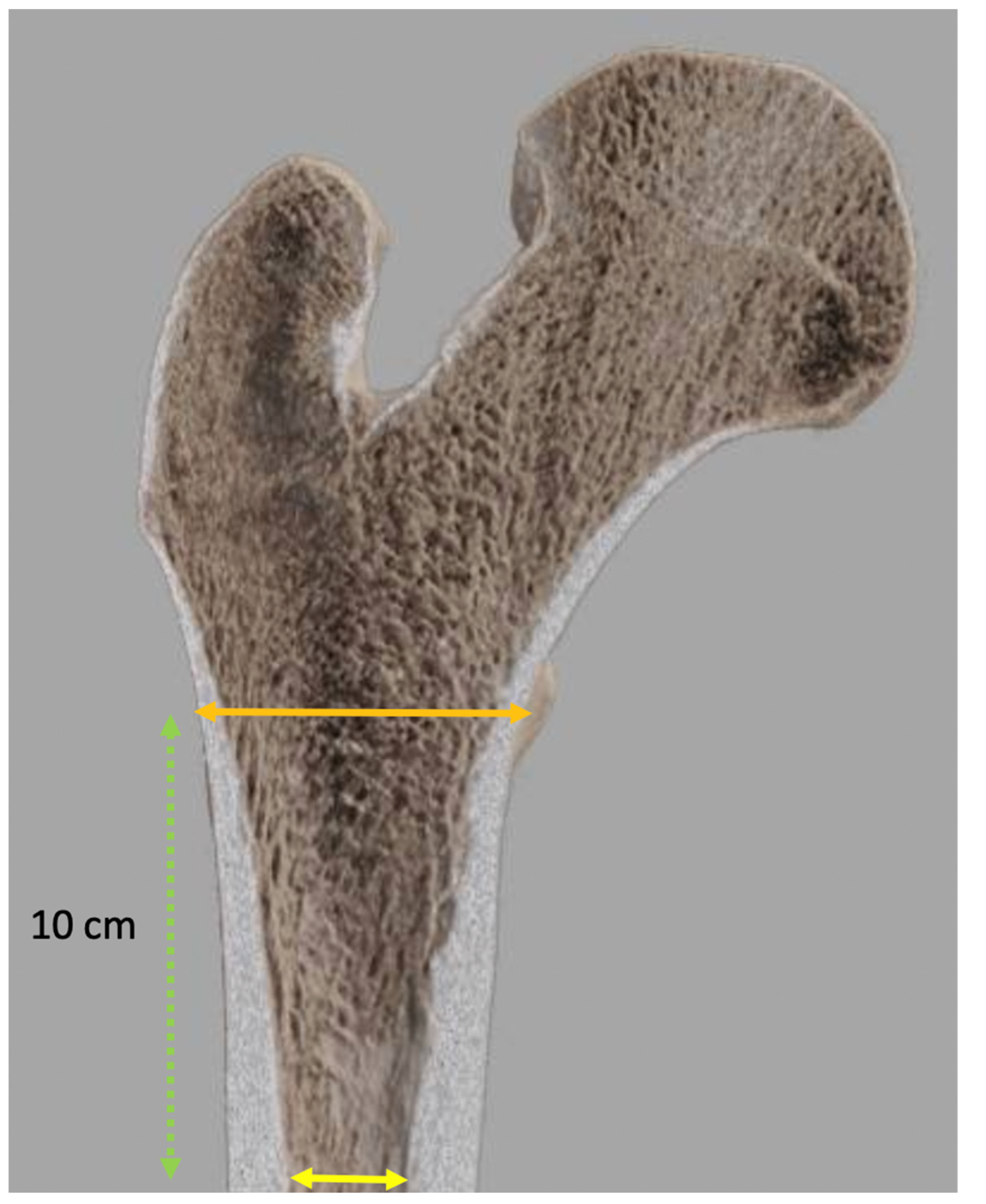
- Dorr, L.D.; Faugere, M.C.; Mackel, A.M.; Gruen, T.A.; Bognar, B.; Malluche, H.H. Structural and Cellular Assessment of Bone Quality of Proximal Femur. Bone 1993, 14, 231–242. [Google Scholar] [CrossRef]
- Blum, A. Prothèse Douloureuse: L’interface Osseuse. In La Hanche; SIMS; Sauramps: Montpellier, France, 2019; Volume 46, pp. 215–231. [Google Scholar]
- Wilkerson, J.; Fernando, N.D. Classifications in Brief: The Dorr Classification of Femoral Bone. Clin. Orthop. Relat. Res. 2020, 478, 1939–1944. [Google Scholar] [CrossRef]
- Singh, M.; Nagrath, A.R.; Maini, P.S. Changes in Trabecular Pattern of the Upper End of the Femur as an Index of Osteoporosis. JBJS 1970, 52, 457–467. [Google Scholar] [CrossRef]
- Sah, A.P.; Thornhill, T.S.; LeBoff, M.S.; Glowacki, J. Correlation of Plain Radiographic Indices of the Hip with Quantitative Bone Mineral Density. Osteoporos. Int. 2007, 18, 1119–1126. [Google Scholar] [CrossRef] [PubMed]
- Knight, J.L.; Atwater, R.D. Preoperative Planning for Total Hip Arthroplasty. Quantitating Its Utility and Precision. J. Arthroplast. 1992, 7 (Suppl. S1), 403–409. [Google Scholar] [CrossRef]
- Salem, H.S.; Marchand, K.B.; Ehiorobo, J.O.; Tarazi, J.M.; Matzko, C.N.; Sodhi, N.; Hepinstall, M.S.; Mont, M.A. Benefits of CT Scanning for the Management of Hip Arthritis and Arthroplasty. Surg. Technol. Int. 2020, 36, 364–370. [Google Scholar] [PubMed]
- Liang, J.; Zhao, Y.; Gao, X.; Fang, X.; Xu, Y.; Lu, S. Design of Custom-Made Navigational Template of Femoral Head and Pilot Research in Total Hip Resurfacing Arthroplasty. BMC Surg. 2020, 20, 144. [Google Scholar] [CrossRef] [PubMed]
- Madadi, F.; Yazdanshenas, H.; Madadi, F.; Bazargan-Hejazi, S. Double Acetabular Wall—A Misleading Point for Hip Arthroplasty: An Anatomical, Radiological, Clinical Study. Int. Orthop. 2013, 37, 1007–1011. [Google Scholar] [CrossRef] [PubMed]
- Sculco, P.K.; Wright, T.; Malahias, M.-A.; Gu, A.; Bostrom, M.; Haddad, F.; Jerabek, S.; Bolognesi, M.; Fehring, T.; Gonzalez DellaValle, A.; et al. The Diagnosis and Treatment of Acetabular Bone Loss in Revision Hip Arthroplasty: An International Consensus Symposium. HSS J. 2022, 18, 8–41. [Google Scholar] [CrossRef]
- Tran, G.; Khalil, L.S.; Wrubel, A.; Klochko, C.L.; Davis, J.J.; Soliman, S.B. Incidental Findings Detected on Preoperative CT Imaging Obtained for Robotic-Assisted Joint Replacements: Clinical Importance and the Effect on the Scheduled Arthroplasty. Skelet. Radiol. 2020, 50, 1151–1161. [Google Scholar] [CrossRef]
- Kobayashi, H.; Cech, A.; Kase, M.; Pagenstart, G.; Carrillon, Y.; O’Loughlin, P.F.; Bothorel, H.; Aït-Si-Selmi, T.; Bonnin, M.P. Pre-Operative Templating in THA. Part II: A CT-Based Strategy to Correct Architectural Hip Deformities. Arch. Orthop. Trauma Surg. 2020, 140, 551–562. [Google Scholar] [CrossRef]
- Mayr, H.O.; Schmidt, J.-P.; Haasters, F.; Bernstein, A.; Schmal, H.; Prall, W.C. Anteversion Angle Measurement in Suspected Torsional Malalignment of the Femur in 3-Dimensional EOS vs Computed Tomography—A Validation Study. J. Arthroplast. 2021, 36, 379–386. [Google Scholar] [CrossRef]
- Veilleux, N.J.; Kalore, N.V.; Vossen, J.A.; Wayne, J.S. Automatic Characterization of Pelvic and Sacral Measures from 200 Subjects. J. Bone Jt. Surg. Am. 2020, 102, e130. [Google Scholar] [CrossRef]
- Liang, S.; Xie, J.; Wang, F.; Jing, J.; Li, J. Application of Three-Dimensional Printing Technology in Peripheral Hip Diseases. Bioengineered 2021, 12, 5883–5891. [Google Scholar] [CrossRef] [PubMed]
- Yan, L.; Wang, P.; Zhou, H.-B. Application of 3D printing guide plate in total hip arthroplasty for developmental dysplasia of the hip. Zhongguo Gu Shang 2020, 33, 1001–1005. [Google Scholar] [CrossRef] [PubMed]
- Huppertz, A.; Radmer, S.; Asbach, P.; Juran, R.; Schwenke, C.; Diederichs, G.; Hamm, B.; Sparmann, M. Computed Tomography for Preoperative Planning in Minimal-Invasive Total Hip Arthroplasty: Radiation Exposure and Cost Analysis. Eur. J. Radiol. 2011, 78, 406–413. [Google Scholar] [CrossRef] [PubMed]
- Sariali, E.; Mauprivez, R.; Khiami, F.; Pascal-Mousselard, H.; Catonné, Y. Accuracy of the Preoperative Planning for Cementless Total Hip Arthroplasty. A Randomised Comparison between Three-Dimensional Computerised Planning and Conventional Templating. Orthop. Traumatol. Surg. Res. 2012, 98, 151–158. [Google Scholar] [CrossRef]
- Wade, R.; Yang, H.; McKenna, C.; Faria, R.; Gummerson, N.; Woolacott, N. A Systematic Review of the Clinical Effectiveness of EOS 2D/3D X-Ray Imaging System. Eur. Spine J. 2013, 22, 296–304. [Google Scholar] [CrossRef]
- Bendaya, S.; Anglin, C.; Lazennec, J.-Y.; Allena, R.; Thoumie, P.; Skalli, W. Good vs Poor Results After Total Hip Arthroplasty: An Analysis Method Using Implant and Anatomic Parameters with the EOS Imaging System. J. Arthroplast. 2016, 31, 2043–2052. [Google Scholar] [CrossRef]
- Park, K.-R.; Lee, J.-H.; Kim, D.-S.; Ryu, H.; Kim, J.; Yon, C.-J.; Lee, S.-W. The Comparison of Lower Extremity Length and Angle between Computed Radiography-Based Teleoroentgenogram and EOS® Imaging System. Diagnostics 2022, 12, 1052. [Google Scholar] [CrossRef]
- Lazennec, J.-Y.; Rousseau, M.-A.; Brusson, A.; Folinais, D.; Amel, M.; Clarke, I.; Pour, A.E. Total Hip Prostheses in Standing, Sitting and Squatting Positions: An Overview of Our 8 Years Practice Using the EOS Imaging Technology. TOORTHJ. 2015, 9, 26–44. [Google Scholar] [CrossRef]
- Tokunaga, K.; Okamoto, M.; Watanabe, K. Implant Orientation Measurement After THA Using the EOS X-Ray Image Acquisition System. Adv. Exp. Med. Biol. 2018, 1093, 335–343. [Google Scholar] [CrossRef]
- Boscher, J.; Alain, A.; Vergnenegre, G.; Hummel, V.; Charissoux, J.-L.; Marcheix, P.-S. Femoral Shaft Fractures Treated by Antegrade Locked Intramedullary Nailing: EOS Stereoradiographic Imaging Evaluation of Rotational Malalignment Having a Functional Impact. Orthop. Traumatol. Surg. Res. 2022, 108, 103235. [Google Scholar] [CrossRef]
- Delin, C.; Silvera, S.; Bassinet, C.; Thelen, P.; Rehel, J.-L.; Legmann, P.; Folinais, D. Ionizing Radiation Doses during Lower Limb Torsion and Anteversion Measurements by EOS Stereoradiography and Computed Tomography. Eur. J. Radiol. 2014, 83, 371–377. [Google Scholar] [CrossRef] [PubMed]
- Deschênes, S.; Charron, G.; Beaudoin, G.; Labelle, H.; Dubois, J.; Miron, M.-C.; Parent, S. Diagnostic Imaging of Spinal Deformities: Reducing Patients Radiation Dose with a New Slot-Scanning X-Ray Imager. Spine 2010, 35, 989–994. [Google Scholar] [CrossRef]
- Lazennec, J.Y.; Rousseau, M.A.; Rangel, A.; Gorin, M.; Belicourt, C.; Brusson, A.; Catonné, Y. Pelvis and Total Hip Arthroplasty Acetabular Component Orientations in Sitting and Standing Positions: Measurements Reproductibility with EOS Imaging System versus Conventional Radiographies. Orthop. Traumatol. Surg. Res. 2011, 97, 373–380. [Google Scholar] [CrossRef] [PubMed]
- Belzunce, M.A.; Henckel, J.; Di Laura, A.; Hart, A. Uncemented Femoral Stem Orientation and Position in Total Hip Arthroplasty: A CT Study. J. Orthop. Res. 2020, 38, 1486–1496. [Google Scholar] [CrossRef] [PubMed]
- Olaiya, O.R.; Nadeem, I.; Horner, N.S.; Bedi, A.; Leroux, T.; Alolabi, B.; Khan, M. Templating in Shoulder Arthroplasty—A Comparison of 2D CT to 3D CT Planning Software: A Systematic Review. Shoulder Elb. 2020, 12, 303–314. [Google Scholar] [CrossRef] [PubMed]
- Freehill, M.T.; Weick, J.W.; Ponce, B.A.; Bedi, A.; Haas, D.; Ruffino, B.; Robbins, C.; Prete, A.M.; Costouros, J.G.; Warner, J.J. Anatomic Total Shoulder Arthroplasty: Component Size Prediction with 3-Dimensional Pre-Operative Digital Planning. J. Shoulder Elb. Arthroplast. 2022, 6, 24715492221098816. [Google Scholar] [CrossRef] [PubMed]
- Blakeney, W.G.; Urvoy, M.; Chaoui, J.; Raiss, P.; Athwal, G.S.; Walch, G. Development and Assessment of 3-Dimensional Computed Tomography Measures of Proximal Humeral Bone Density: A Comparison to Established 2-Dimensional Measures and Intraoperative Findings in Patients Undergoing Shoulder Arthroplasty. JSES Int. 2021, 5, 1008–1013. [Google Scholar] [CrossRef] [PubMed]
- Werner, B.C.; Denard, P.J.; Tokish, J.M.; Bedi, A.; Donegan, R.P.; Metcalfe, N.; Dines, J.S. The Addition of Preoperative Three-Dimensional Analysis Alters Implant Choice in Shoulder Arthroplasty. Shoulder Elb. 2022, 14, 378–384. [Google Scholar] [CrossRef] [PubMed]
- Klag, E.A.; Lizzio, V.A.; Charters, M.A.; Ayoola, A.S.; Wesemann, L.; Banka, T.R.; North, W.T. Increased Accuracy in Templating for Total Knee Arthroplasty Using 3D Models Generated from Radiographs. J. Knee Surg. 2022. [Google Scholar] [CrossRef]
- Tiefenboeck, S.; Sesselmann, S.; Taylor, D.; Forst, R.; Seehaus, F. Preoperative Planning of Total Knee Arthroplasty: Reliability of Axial Alignment Using a Three-Dimensional Planning Approach. Acta Radiol. 2022, 63, 1051–1061. [Google Scholar] [CrossRef]
- Gu, F.; Li, L.; Zhang, H.; Li, X.; Ling, C.; Wang, L.; Yao, Q. Three-Dimensional-Printed Guiding Template for Unicompartmental Knee Arthroplasty. BioMed Res. Int. 2020, 2020, 7019794. [Google Scholar] [CrossRef] [PubMed]
- Kunze, K.N.; Polce, E.M.; Patel, A.; Courtney, P.M.; Sporer, S.M.; Levine, B.R. Machine Learning Algorithms Predict within One Size of the Final Implant Ultimately Used in Total Knee Arthroplasty with Good-to-Excellent Accuracy. Knee Surg. Sports Traumatol. Arthrosc. 2022, 30, 2565–2572. [Google Scholar] [CrossRef] [PubMed]
- Lazennec, J.-Y.; Brusson, A.; Rousseau, M.-A. Hip-Spine Relations and Sagittal Balance Clinical Consequences. Eur. Spine J. 2011, 20 (Suppl. S5), 686–698. [Google Scholar] [CrossRef] [PubMed] [Green Version]


| Parameter | Utility |
|---|---|
| Magnification | Measurement adaptation |
| Pelvic axis (teardrop sign) | Limb length discrepancy |
| Frontal inclination of the acetabular component | |
| Femoro-acetabular joint rotation center | Acetabular component positioning and size determination |
| Width of the endosteal diaphyseal and metaphyseal canal diaphysis | Size of the femoral component |
| Femoral offset determination | |
| Matching of femoral head and joint centers | |
| Positioning of the femoral component | |
| Femoral neck resection length | Positioning of the femoral component |
| Cervico-diaphyseal angle | |
| Height and diameter of the femoral head |
| Radiographs (2D) | CT and EOS Imaging (3D) | |
|---|---|---|
| Advantages/Strenghts |
| EOS imaging:
|
| Drawbacks |
| EOS imaging:
|
Publisher’s Note: MDPI stays neutral with regard to jurisdictional claims in published maps and institutional affiliations. |
© 2022 by the authors. Licensee MDPI, Basel, Switzerland. This article is an open access article distributed under the terms and conditions of the Creative Commons Attribution (CC BY) license (https://creativecommons.org/licenses/by/4.0/).
Share and Cite
Germain, E.; Lombard, C.; Boubaker, F.; Louis, M.; Blum, A.; Gondim-Teixeira, P.A.; Gillet, R. Imaging in Hip Arthroplasty Management—Part 1: Templating: Past, Present and Future. J. Clin. Med. 2022, 11, 5465. https://doi.org/10.3390/jcm11185465
Germain E, Lombard C, Boubaker F, Louis M, Blum A, Gondim-Teixeira PA, Gillet R. Imaging in Hip Arthroplasty Management—Part 1: Templating: Past, Present and Future. Journal of Clinical Medicine. 2022; 11(18):5465. https://doi.org/10.3390/jcm11185465
Chicago/Turabian StyleGermain, Edouard, Charles Lombard, Fatma Boubaker, Mathias Louis, Alain Blum, Pedro Augusto Gondim-Teixeira, and Romain Gillet. 2022. "Imaging in Hip Arthroplasty Management—Part 1: Templating: Past, Present and Future" Journal of Clinical Medicine 11, no. 18: 5465. https://doi.org/10.3390/jcm11185465