Novel Polymeric Thin-Film Composite Membranes for High-Temperature Gas Separations

 , , , , and
Abstract
:1. Introduction
2. Experimental
2.1. Materials
2.1.1. Non-Woven Support
2.1.2. Polymers
2.1.3. Solvents
2.1.4. Gases
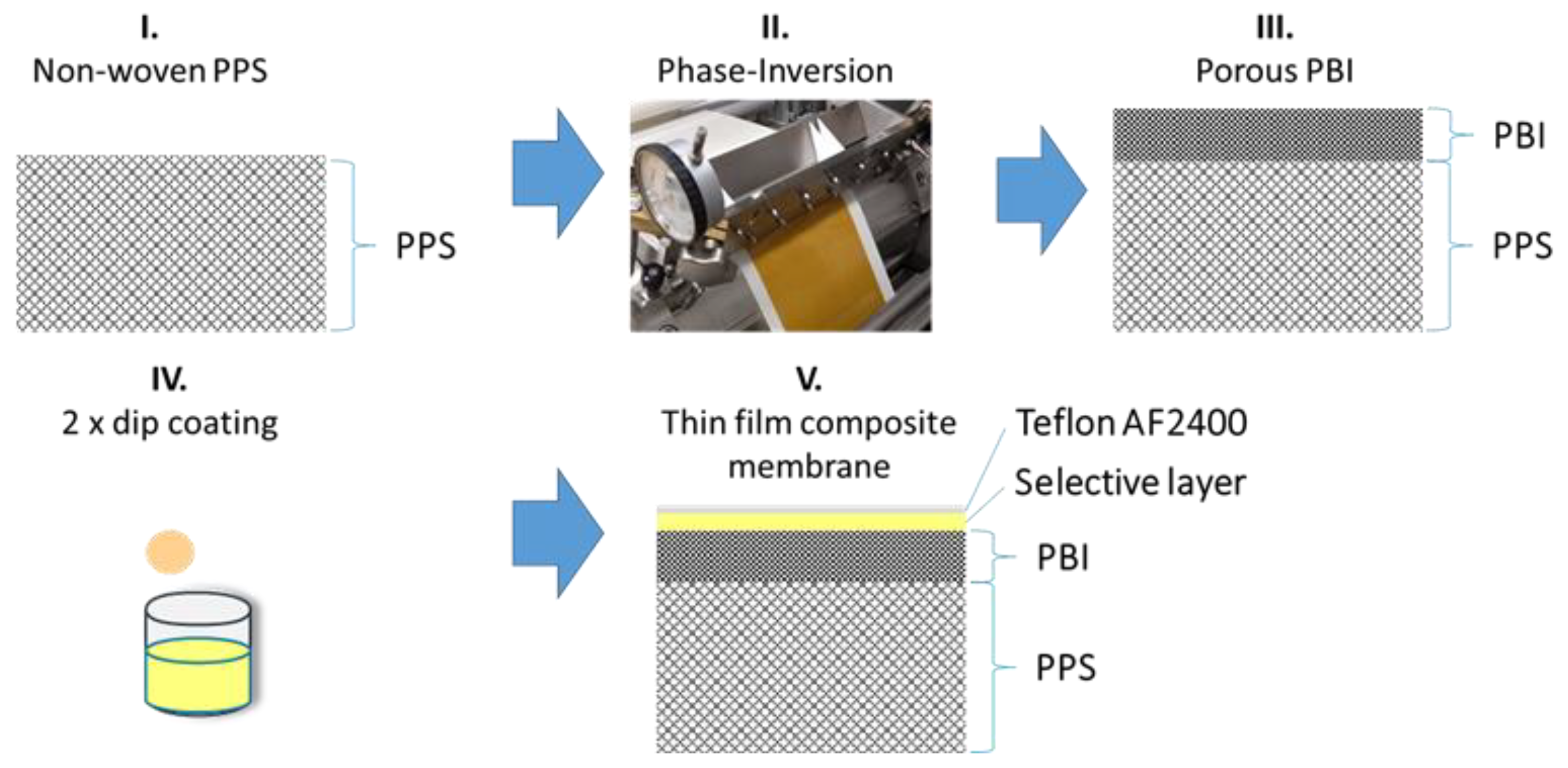
2.2. Membranes
2.2.1. Thick Films
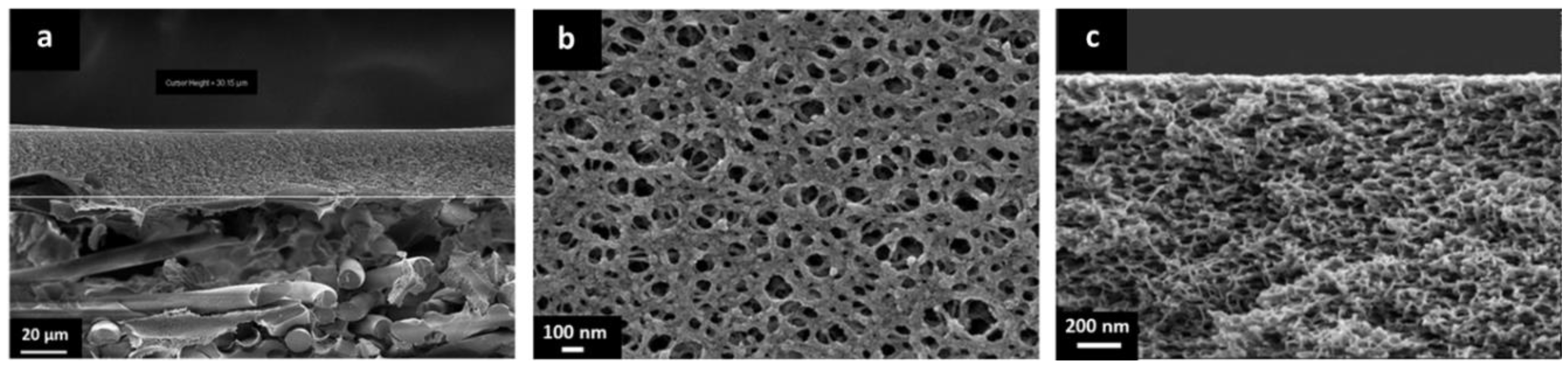
2.2.2. Preparation of TFCMs
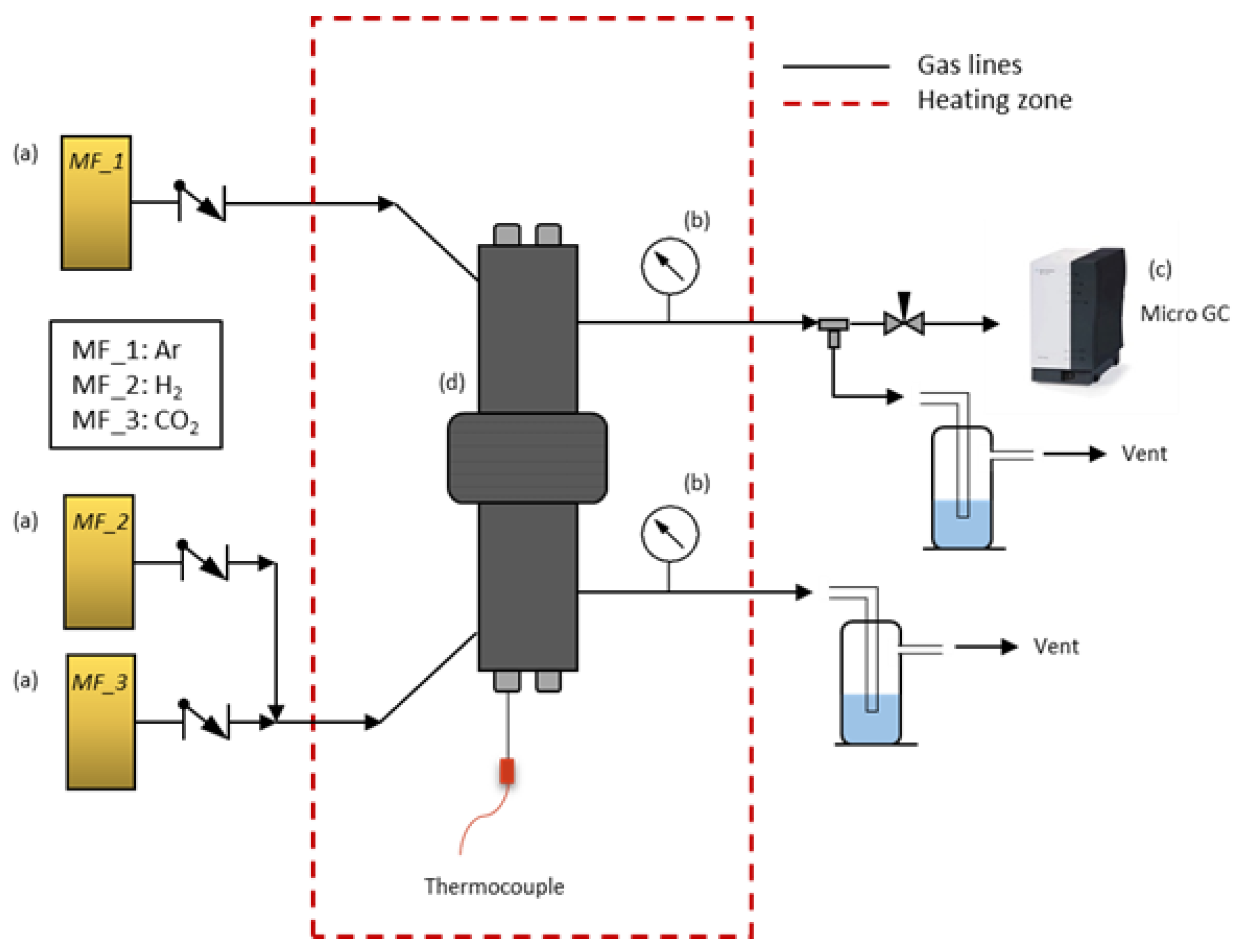
2.3. Characterization Methods
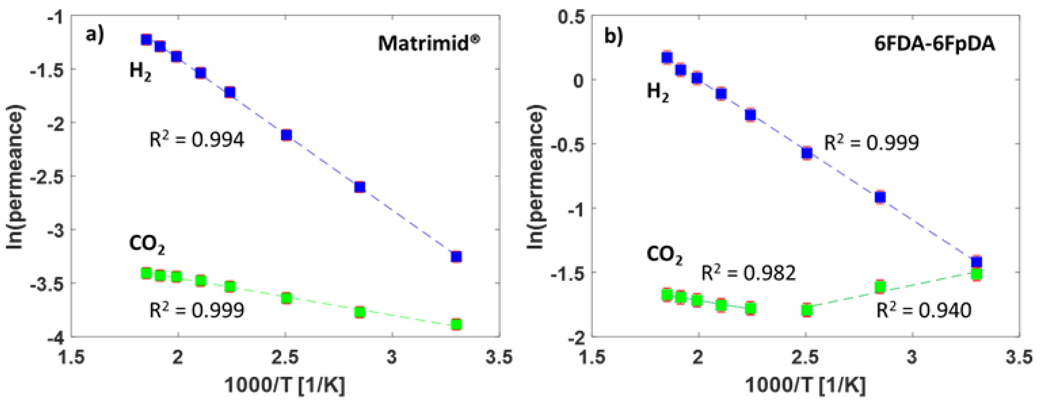
3. Results and Discussion
4. Conclusions and Outlook
Author Contributions
Funding
Acknowledgments
Conflicts of Interest
References
- Baker, R.W.; Staff, U.B. Membrane technology. In Kirk-Othmer Encyclopedia of Chemical Technology; J. Wiley & Sons: New York, NY, USA, 2000. [Google Scholar]
- Ladewig, B.; Al-Shaeli, M.N.Z. Fundamentals of Membrane Processes. In Fundamentals of Membrane Bioreactors: Materials, Systems and Membrane Fouling; Springer: Singapore, 2017; pp. 13–37. [Google Scholar]
- Ismail, A.F.; Khulbe, K.C.; Matsuura, T. Gas Separation Membranes; Springer: Singapore, 2015; Volume 7. [Google Scholar]
- Amooghin, A.E.; Sanaeepur, H.; Pedram, M.Z.; Omidkhah, M.; Kargari, A. New advances in polymeric membranes for CO2 separation. In Polymer Science: Research Advances, Practical Applications and Educational Aspects; Formatex Research Center: Badajoz, Spain, 2016; pp. 354–368. [Google Scholar]
- Schuldt, K.; Pohlmann, J.; Shishatskiy, S.; Brinkmann, T. Applicability of PolyActive™ Thin Film Composite Membranes for CO2 Separation from C2H4 Containing Multi-Component Gas Mixtures at Pressures up to 30 Bar. Membranes 2018, 8, 27. [Google Scholar] [CrossRef] [PubMed]
- Brinkmann, T.; Lillepärg, J.; Notzke, H.; Pohlmann, J.; Shishatskiy, S.; Wind, J.; Wolff, T. Development of CO2 Selective Poly (Ethylene Oxide)-Based Membranes: From Laboratory to Pilot Plant Scale. Engineering 2017, 3, 485–493. [Google Scholar] [CrossRef]
- Peter, J.; Peinemann, K.-V. Multilayer composite membranes for gas separation based on crosslinked PTMSP gutter layer and partially crosslinked Matrimid® 5218 selective layer. J. Membr. Sci. 2009, 340, 62–72. [Google Scholar] [CrossRef]
- Shishatskiy, S.; Nistor, C.; Popa, M.; Nunes, S.P.; Peinemann, K.V. Polyimide asymmetric membranes for hydrogen separation: Influence of formation conditions on gas transport properties. Adv. Eng. Mater. 2006, 8, 390–397. [Google Scholar] [CrossRef]
- Bai, J.; Founda, A.E.; Matsuura, T.; Hazlett, J.D. A study on the preparation and performance of polydimethylsiloxane-coated polyetherimide membranes in pervaporation. J. Appl. Polym. Sci. 1993, 48, 999–1008. [Google Scholar] [CrossRef]
- Grünauer, J.; Filiz, V.; Shishatskiy, S.; Abetz, C.; Abetz, V. Scalable application of thin film coating techniques for supported liquid membranes for gas separation made from ionic liquids. J. Membr. Sci. 2016, 518, 178–191. [Google Scholar] [CrossRef]
- Escorihuela, S.; Tena, A.; Shishatskiy, S.; Escolástico, S.; Brinkmann, T.; Serra, J.; Abetz, V. Gas Separation Properties of Polyimide Thin Films on Ceramic Supports for High Temperature Applications. Membranes 2018, 8, 16. [Google Scholar] [CrossRef]
- Lu, G.; Da Costa, J.D.; Duke, M.; Giessler, S.; Socolow, R.; Williams, R.H.; Kreutz, T. Inorganic membranes for hydrogen production and purification: A critical review and perspective. J. Colloid Interface Sci. 2007, 314, 589–603. [Google Scholar] [CrossRef] [PubMed]
- David, O.C.; Gorri, D.; Urtiaga, A.; Ortiz, I. Mixed gas separation study for the hydrogen recovery from H2/CO/N2/CO2 post combustion mixtures using a Matrimid membrane. J. Membr. Sci. 2011, 378, 359–368. [Google Scholar] [CrossRef]
- Koros, W.J.; Fleming, G. Membrane-based gas separation. J. Membr. Sci. 1993, 83, 1–80. [Google Scholar] [CrossRef]
- Liaw, D.-J.; Wang, K.L.; Huang, Y.C.; Lee, K.R.; Lai, J.Y.; Ha, C.S. Advanced polyimide materials: Syntheses, physical properties and applications. Prog. Polym. Sci. 2012, 37, 907–974. [Google Scholar] [CrossRef]
- Weigelt, F.; Georgopanos, P.; Shishatskiy, S.; Filiz, V.; Brinkmann, T.; Abetz, V. Development and Characterization of Defect-Free Matrimid® Mixed-Matrix Membranes Containing Activated Carbon Particles for Gas Separation. Polymers 2018, 10, 51. [Google Scholar] [CrossRef]
- Melin, T.; Rautenbach, R. Membranverfahren: Grundlagen der Modul-und Anlagenauslegung; Springer-Verlag: Berlin, Germany, 2007. [Google Scholar]
- Barrer, R.; Rideal, E.K. Permeation, diffusion and solution of gases in organic polymers. Trans. Faraday Soc. 1939, 35, 628–643. [Google Scholar] [CrossRef]
- Bains, P.; Psarras, P.; Wilcox, J. CO2 capture from the industry sector. Prog. Energy Combust. Sci. 2017, 63, 146–172. [Google Scholar] [CrossRef]
- Malerød-Fjeld, H.; Clark, D.; Yuste-Tirados, I.; Zanón, R.; Catalán-Martinez, D.; Beeaff, D.; Morejudo, S.H.; Vestre, P.K.; Norby, T.; Haugsrud, R.; et al. Thermo-electrochemical production of compressed hydrogen from methane with near-zero energy loss. Nat. Energy 2017, 2, 923–931. [Google Scholar] [CrossRef]
- Stolten, D.; Emonts, B. Hydrogen Science and Engineering, 2 Volume Set: Materials, Processes, Systems, and Technology; John Wiley & Sons: Hoboken, NJ, USA, 2016; Volume 1. [Google Scholar]
- Rezakazemi, M.; Sadrzadeh, M.; Matsuura, T. Thermally stable polymers for advanced high-performance gas separation membranes. Prog. Energy Combust. Sci. 2018, 66, 1–41. [Google Scholar] [CrossRef]
- Pesiri, D.R.; Jorgensen, B.; Dye, R.C. Thermal optimization of polybenzimidazole meniscus membranes for the separation of hydrogen, methane, and carbon dioxide. J. Membr. Sci. 2003, 218, 11–18. [Google Scholar] [CrossRef]
- Kumbharkar, S.C.; Liu, Y.; Li, K. High performance polybenzimidazole based asymmetric hollow fibre membranes for H2/CO2 separation. J. Membr. Sci. 2011, 375, 231–240. [Google Scholar] [CrossRef]
- Berchtold, K.A.; Singh, R.P.; Young, J.S.; Dudeck, K.W. Polybenzimidazole composite membranes for high temperature synthesis gas separations. J. Membr. Sci. 2012, 415, 265–270. [Google Scholar] [CrossRef]
- Costello, L.M.; Koros, W.J. Thermally stable polyimide isomers for membrane-based gas separations at elevated temperatures. J. Polym. Sci. Part B 1995, 33, 135–146. [Google Scholar] [CrossRef]
- Muñoz, D.M.; de La Campa, J.G.; de Abajo, J.; Lozano, A.E. Experimental and theoretical study of an improved activated polycondensation method for aromatic polyimides. Macromolecules 2007, 40, 8225–8232. [Google Scholar] [CrossRef]
- Herdegen, V.; Werner, A.; Milew, K.; Haseneder, R.; Aubel, T. ACHEMA 2018: Membranes and Membrane Separation. Chem. Ing. Tech. 2018, 90, 1964–1971. [Google Scholar] [CrossRef]
- Wang, K.Y.; Chung, T.-S. Fabrication of polybenzimidazole (PBI) nanofiltration hollow fiber membranes for removal of chromate. J. Membr. Sci. 2006, 281, 307–315. [Google Scholar] [CrossRef]
- Ansaloni, L.; Minelli, M.; Baschetti, M.G.; Sarti, G.C. Effects of thermal treatment and physical aging on the gas transport properties in Matrimid®. Oil Gas Sci. Technol. 2015, 70, 367–379. [Google Scholar] [CrossRef]
- Pye, D.; Hoehn, H.; Panar, M. Measurement of gas permeability of polymers. I. Permeabilities in constant volume/variable pressure apparatus. J. Appl. Polym. Sci. 1976, 20, 1921–1931. [Google Scholar] [CrossRef]
- Tena, A.; Shishatskiy, S.; Meis, D.; Wind, J.; Filiz, V.; Abetz, V. Influence of the composition and imidization route on the chain packing and gas separation properties of fluorinated copolyimides. Macromolecules 2017, 50, 5839–5849. [Google Scholar] [CrossRef]


| Polymer | Parameter | Gases | Selectivity (-) | |||||
|---|---|---|---|---|---|---|---|---|
| H2 | CO2 | O2 | CH4 | N2 | O2/N2 | CO2/CH4 | ||
| Matrimid® | Permeability (Barrer) * | 18.9 | 7.14 | 1.62 | 0.20 | 0.26 | 6.2 | 35.7 |
| EA (kJ mol−1) | 13.0 | 8.15 | 8.93 | 18.0 | 22.6 | - | - | |
| 6FDA-6FpDA | Permeability (Barrer) * | 74.3 | 53.4 | 10.3 | 1.12 | 1.89 | 5.4 | 47.6 |
| EA (kJ mol−1) | 3.67 | 0.57 | 3.31 | 7.02 | 6.43 | - | - | |
| Teflon® AF 2400 | Permeability (Barrer) * | 1180 | 1248 | 504 | 155 | 222 | 2.3 | 8.1 |
| EA (kJ mol−1) | 5.14 | −3.01 | 3.40 | 9.12 | 7.38 | - | - | |
| Polymer | Parameter | Gases | ||||
|---|---|---|---|---|---|---|
| H2 | CO2 | O2 | CH4 | N2 | ||
| Matrimid® | Permeance, 102 (mSTP3 m 2 h−1 bar−1) * | 4.57 | 2.11 | 0.51 | 0.06 | 0.08 |
| Activation Energy (EA) (kJ mol−1) | 12.3 | 6.24 | 7.13 | 20.0 | 14.6 | |
| Selective layer thickness ** (nm) | 1120 | 930 | 870 | 1280 | 1330 | |
| 6FDA-6FpDA | Permeance, 102 (mSTP3 m−2 h−1 bar−1) * | 46.1 | 41.3 | 8.35 | 1.23 | 2.05 |
| Activation Energy (EA) (kJ mol−1) | 5.58 | −3.45 | 3.08 | 8.95 | 6.51 | |
| Selective layer thickness ** (nm) | 440 | 350 | 340 | 250 | 250 | |
| Matrimid® | 6FDA-6FpDA | |||||
|---|---|---|---|---|---|---|
| Permeance, 102 (mSTP3 m−2 h−1 bar−1) | ||||||
| T (°C) | H2 | CO2 | αH2/CO2 | H2 | CO2 | αH2/CO2 |
| 30 | 3.86 | 2.05 | 1.88 | 24.2 | 22.0 | 1.10 |
| 78 | 7.40 | 2.30 | 3.22 | 40.1 | 20.0 | 2.01 |
| 125 | 12.0 | 2.62 | 4.58 | 56.5 | 16.6 | 3.40 |
| 173 | 18.0 | 2.92 | 6.16 | 76.0 | 16.8 | 4.52 |
| 202 | 21.4 | 3.09 | 6.92 | 89.6 | 17.3 | 5.18 |
| 230 | 25.0 | 3.21 | 7.89 | 101 | 18.0 | 5.61 |
| 248 | 27.5 | 3.24 | 8.49 | 107 | 18.4 | 5.82 |
| 266 | 29.3 | 3.31 | 8.85 | 118 | 18.8 | 6.28 |
| EA (kJ mol−1) | 11.8 | 2.89 | - | 9.02 | −2.91 (30–125 °C) 2.45 (173–266 °C) | - |
© 2019 by the authors. Licensee MDPI, Basel, Switzerland. This article is an open access article distributed under the terms and conditions of the Creative Commons Attribution (CC BY) license (http://creativecommons.org/licenses/by/4.0/).
Share and Cite
Weigelt, F.; Escorihuela, S.; Descalzo, A.; Tena, A.; Escolástico, S.; Shishatskiy, S.; Serra, J.M.; Brinkmann, T. Novel Polymeric Thin-Film Composite Membranes for High-Temperature Gas Separations. Membranes 2019, 9, 51. https://doi.org/10.3390/membranes9040051
Weigelt F, Escorihuela S, Descalzo A, Tena A, Escolástico S, Shishatskiy S, Serra JM, Brinkmann T. Novel Polymeric Thin-Film Composite Membranes for High-Temperature Gas Separations. Membranes. 2019; 9(4):51. https://doi.org/10.3390/membranes9040051
Chicago/Turabian StyleWeigelt, Fynn, Sara Escorihuela, Alberto Descalzo, Alberto Tena, Sonia Escolástico, Sergey Shishatskiy, Jose Manuel Serra, and Torsten Brinkmann. 2019. "Novel Polymeric Thin-Film Composite Membranes for High-Temperature Gas Separations" Membranes 9, no. 4: 51. https://doi.org/10.3390/membranes9040051