
Study of the Removal Efficiency of Chromium Ions Using a Membrane by Electro-Kinetic Technique from Sludge

Abstract
:1. Introduction
2. Materials
2.1. Contaminants
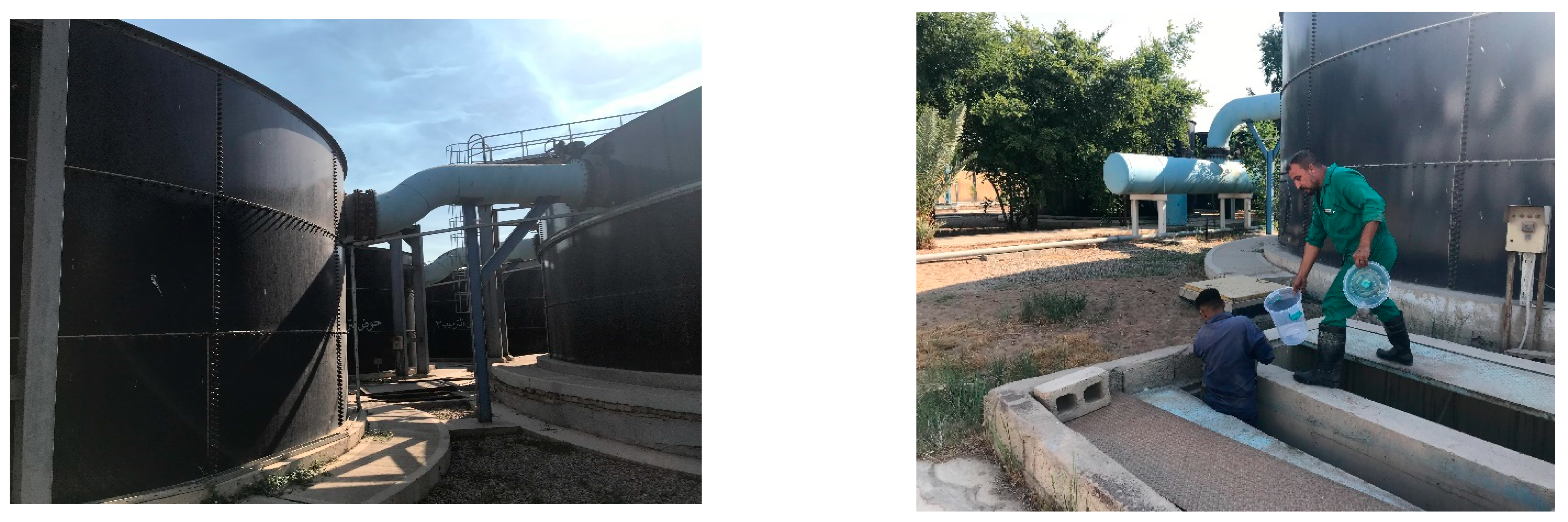
2.2. Sludge
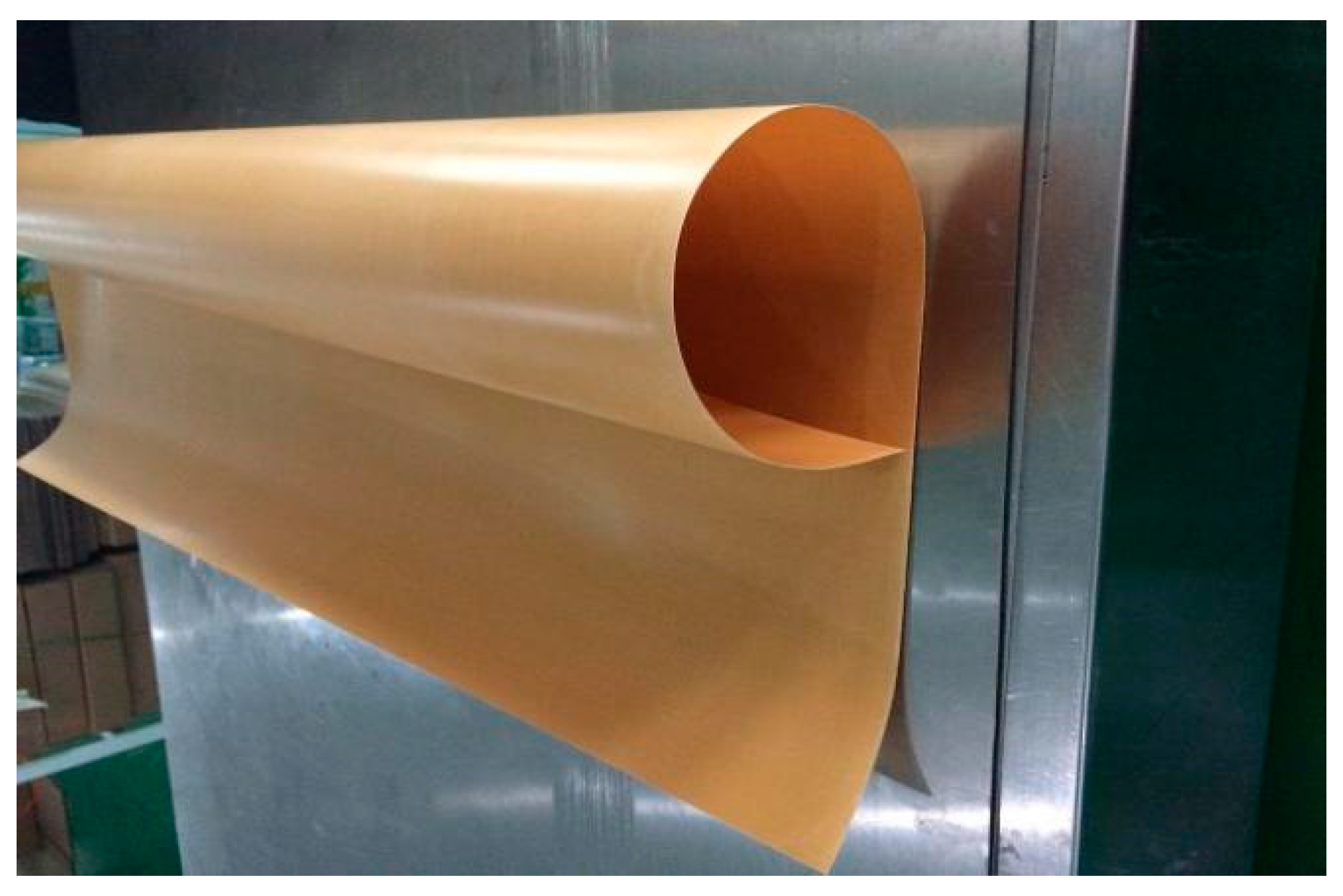
2.3. Membrane
2.4. Acetic Acid (AA)
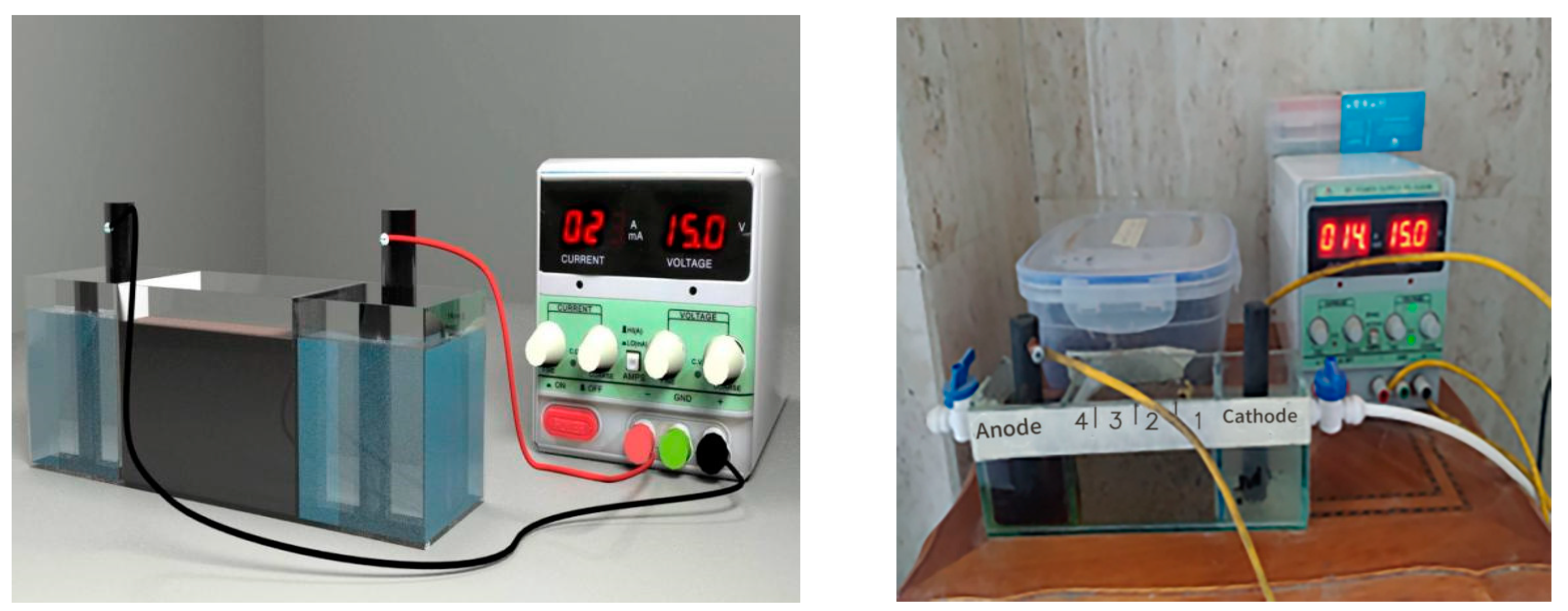
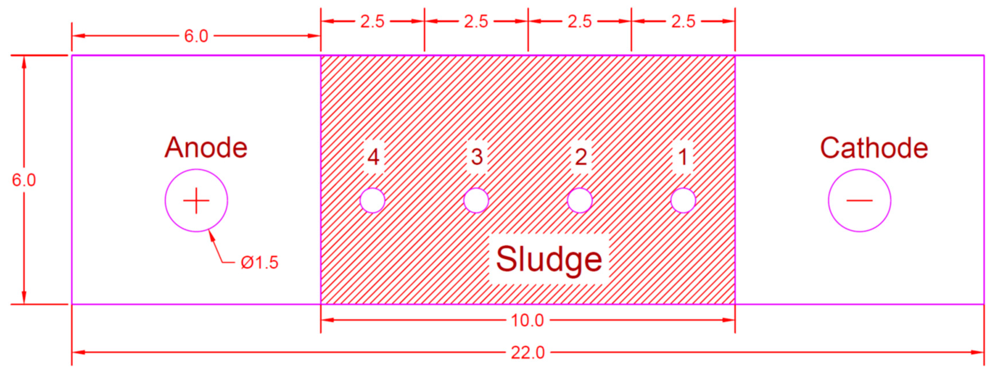
3. Experimental Setup
Analysis of Samples
4. Results and Discussion
4.1. Sludge Analyses
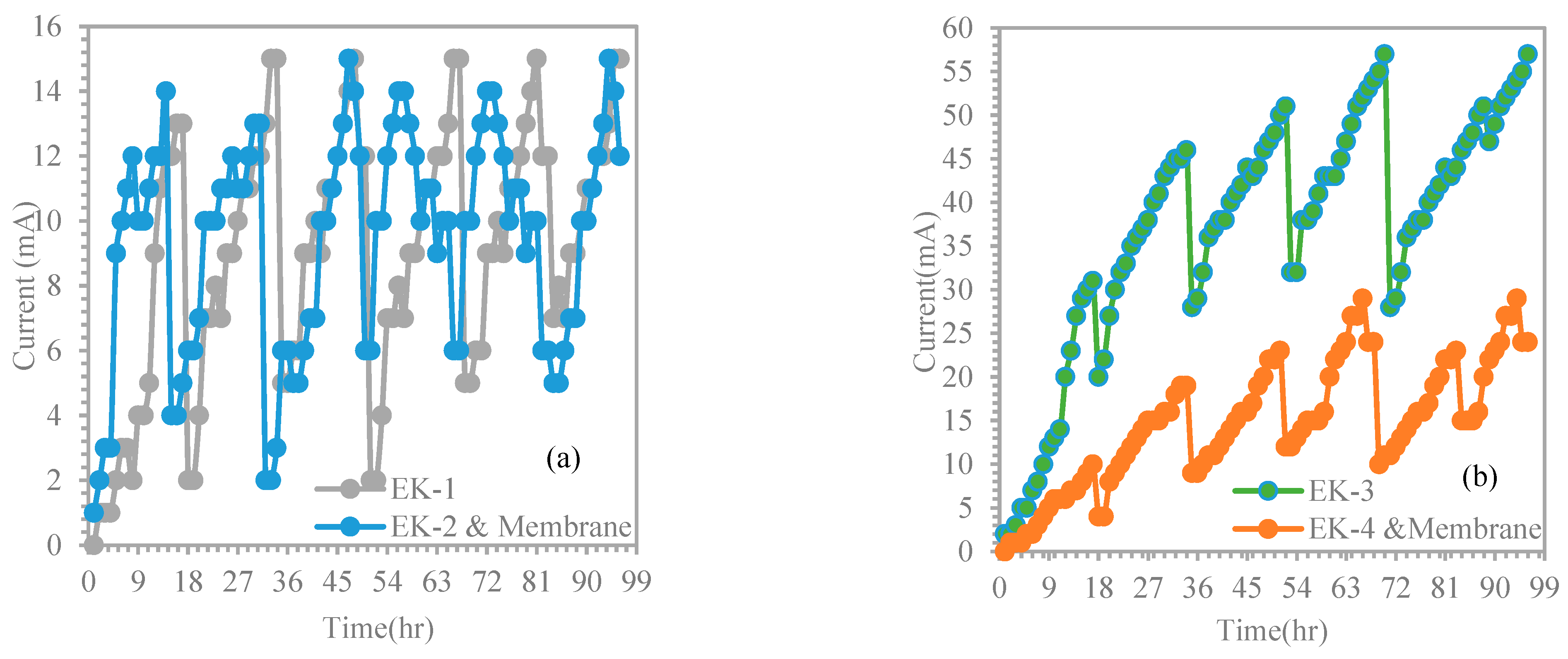
4.2. Experiment Methodology
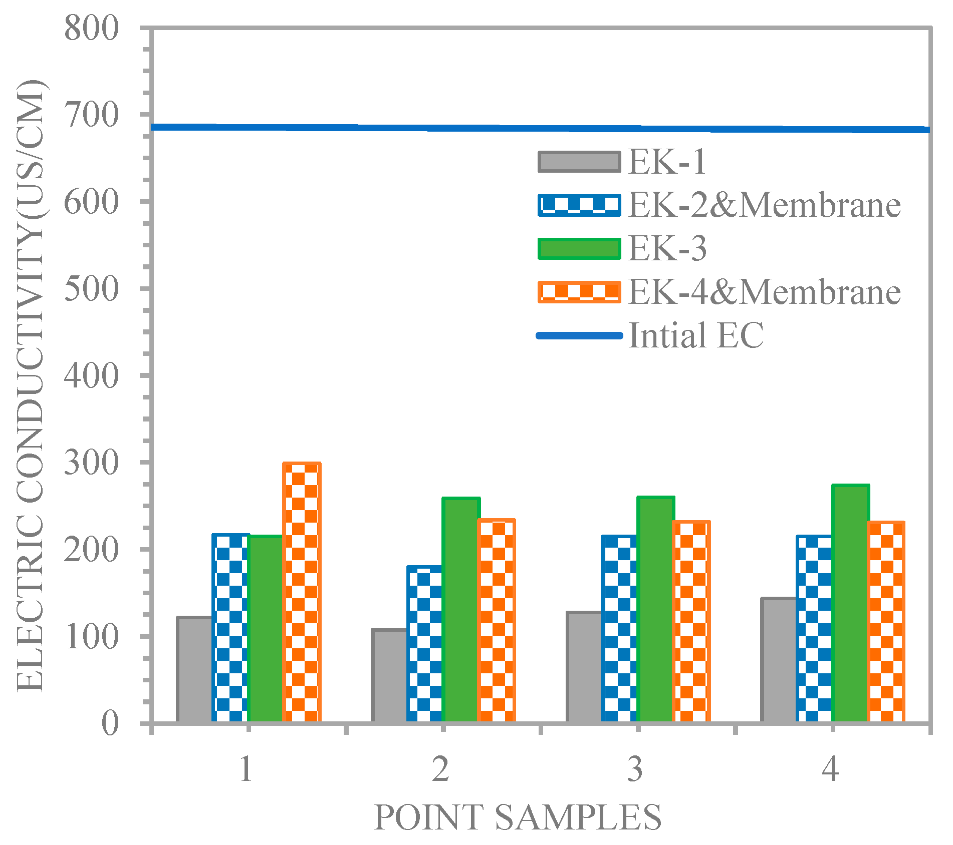
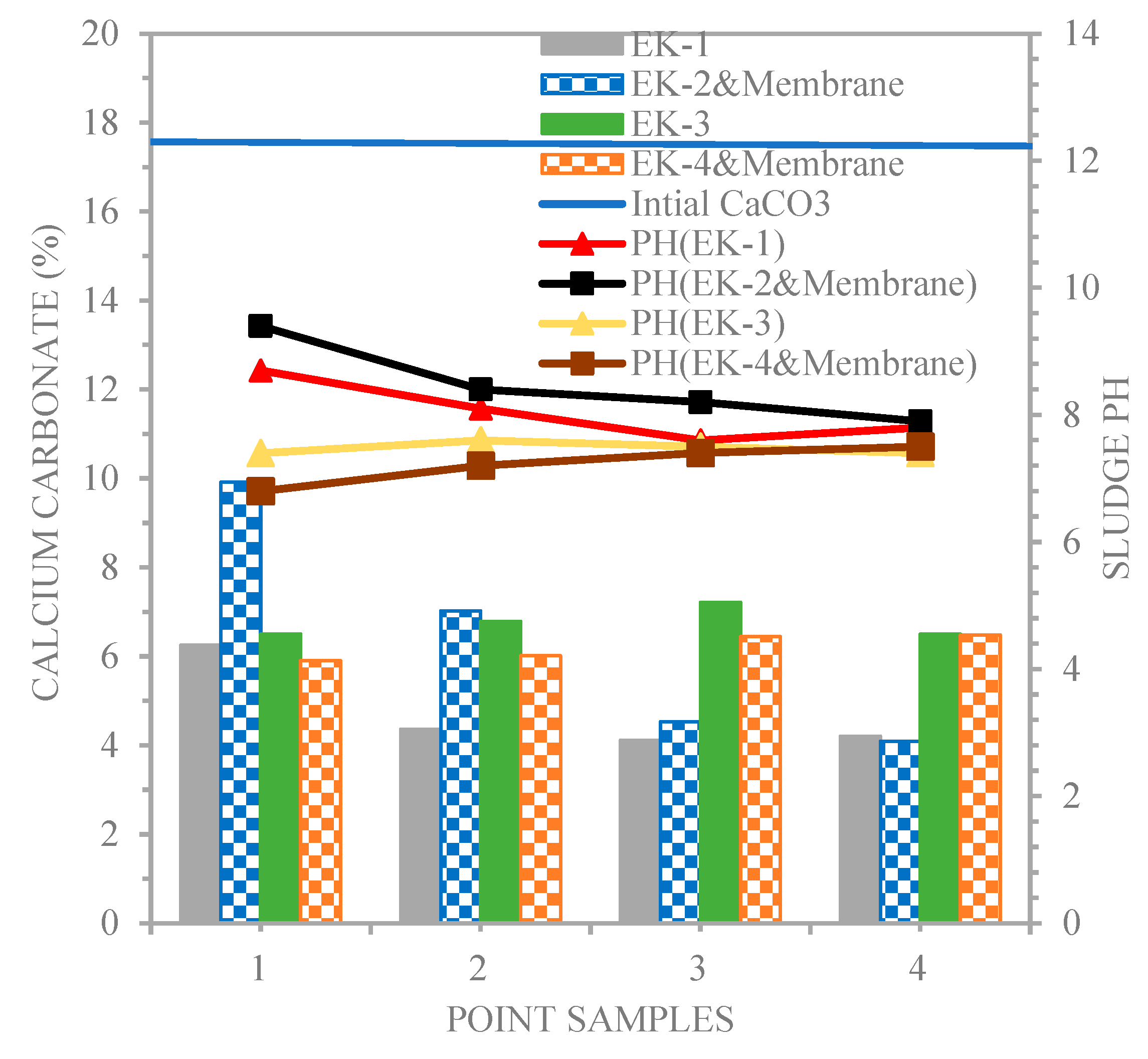
4.2.1. Effect of Electro-Kinetic Remediation with Chromium-Contaminated Soil on the Chemical Properties
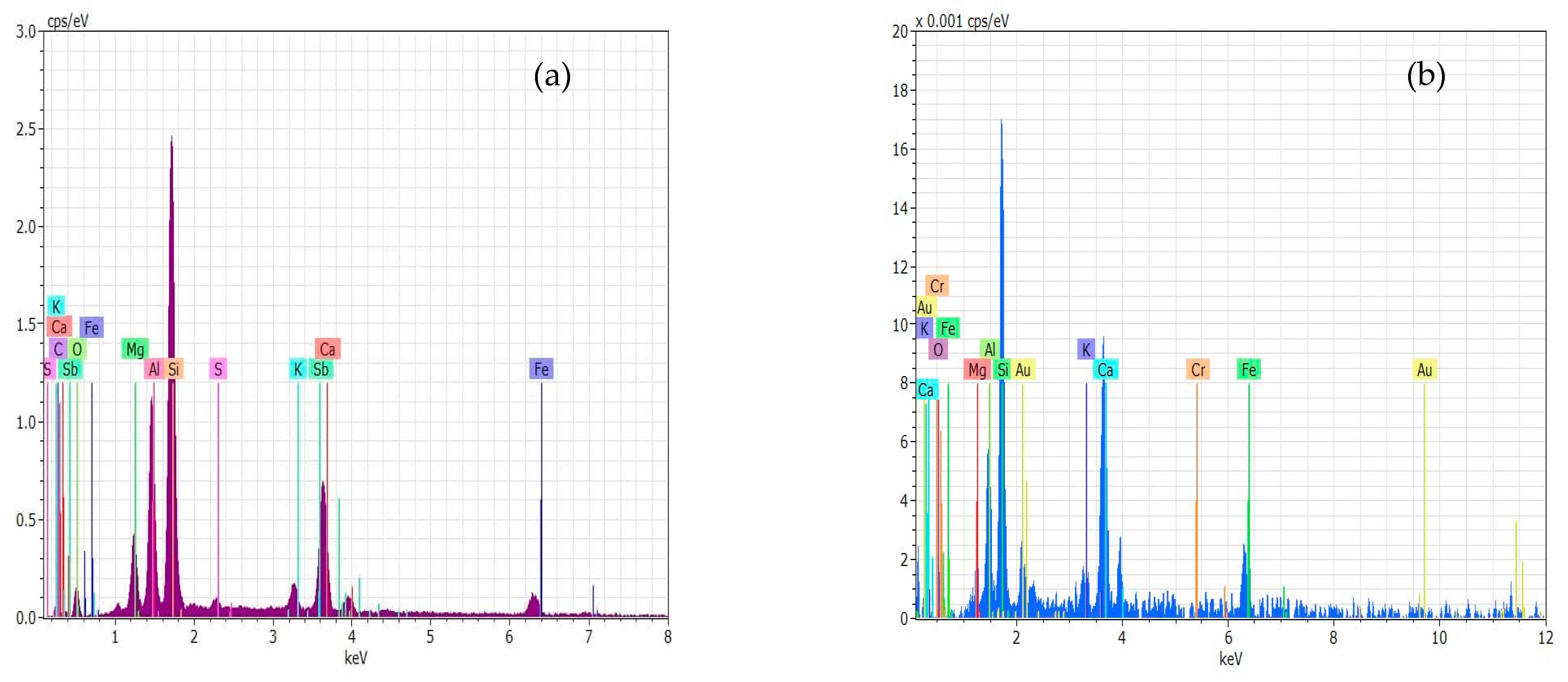
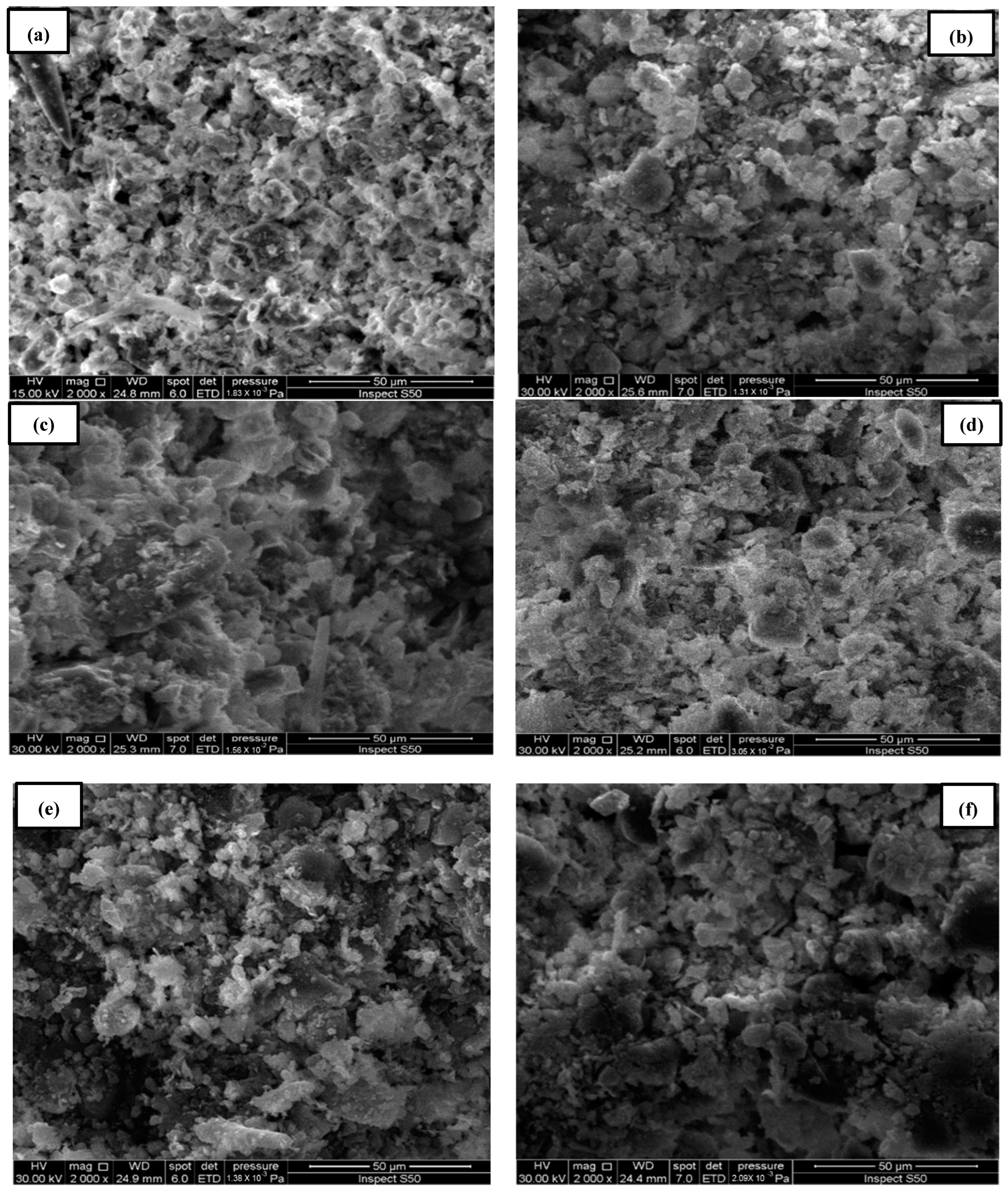
4.2.2. Scanning Electron Microscopy (SEM) of Sludge Samples
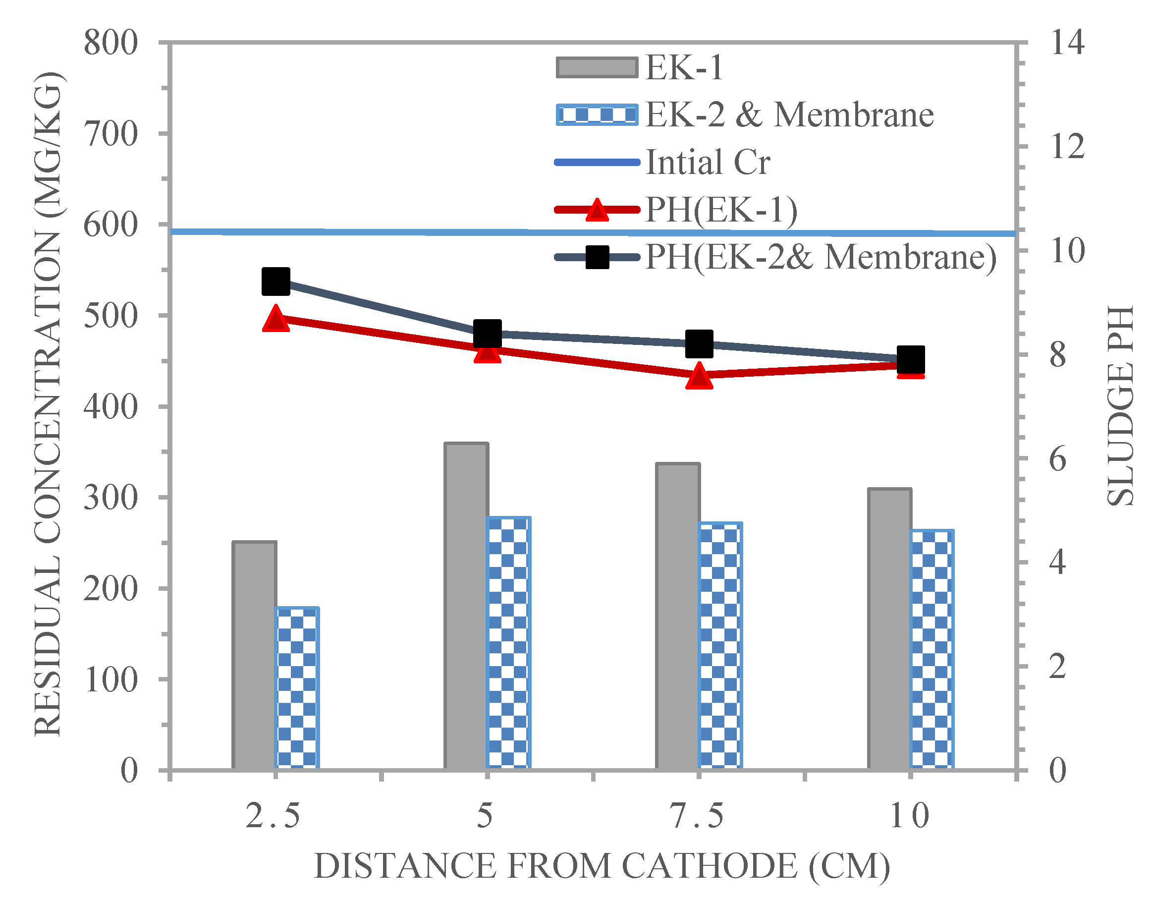
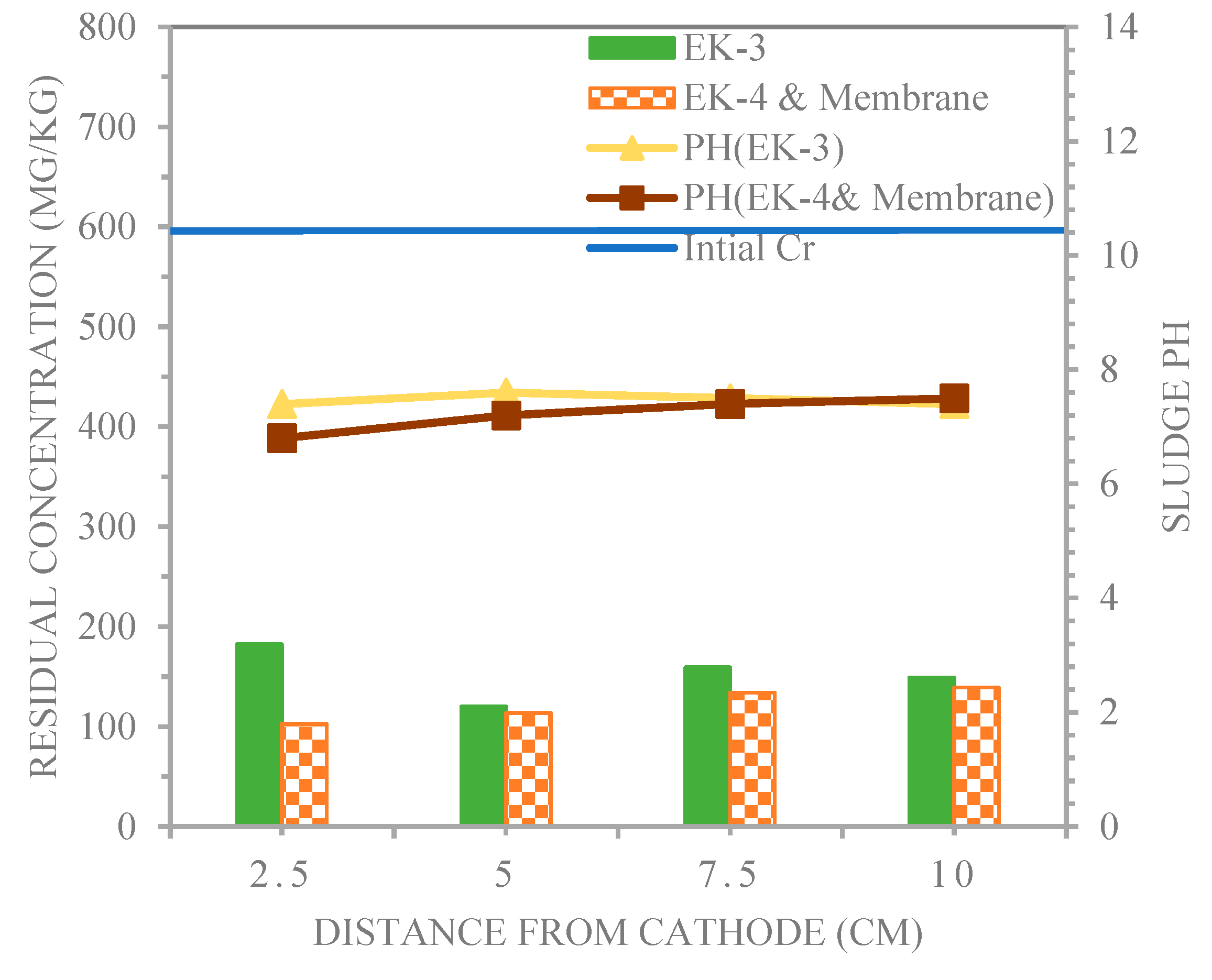
4.3. Distributions for pH and Chromium in the Electro-Kinetic Experiments
5. Conclusions
- The electro-kinetic and membrane techniques exhibited higher Cr3+ removal efficiencies compared to electro-kinetic techniques performed under similar purging solution conditions.
- The electro-kinetic process offers the advantage of using the membrane technique, in which there is no accumulation of chromium at all the sampling points of all the experiments, and this is a success in itself.
- The membrane technique for acetic acid as a catholyte witnessed an excessively low pH of 6.8 in the EK4 and membrane system at point 1 sampling points in the remediation of chromium-contaminated sludge. In addition to providing a higher removal efficiency using the same acetic acid, the average removal efficiencies for the EK3 and EK4 and membrane methods were 74.4% and 79.6% at the 1, 2, 3, and 4 sampling points, respectively.
Author Contributions
Funding
Data Availability Statement
Acknowledgments
Conflicts of Interest
References
- Acar, Y.B.; Alshawabkeh, A.N. Electrokinetic Remediation. I: Pilot-Scale Tests with Lead-Spiked Kaolinite. J. Geotech. Eng. 1996, 122, 173–185. [Google Scholar] [CrossRef]
- Almeira, J.; Peng, C.; Wang, Z. Effect of different electrode configurations on the migration of copper ions during the electrokinetic remediation process. Asia-Pac. J. Chem. Eng. 2009, 4, 581–585. [Google Scholar] [CrossRef]
- Al-Khafaji, Z.S.; Jafer, H.; Dulaimi, A.; Atherton, W.; Al Masoodi, Z. The Soft Soil Stabilisation Using Binary Blending of Ordinary Portland Cement And High Alumina Silica Waste Material. In Proceedings of the 3rd BUiD Doctoral Research Conference, the British University in Dubai, Dubai, United Arab Emirates, 13 May 2017. [Google Scholar]
- Al-Khafaji, Z.S.; Al-Naely, H.K.; Al-Najar, A.E. A Review Applying Industrial Waste Materials in Stabilisation of Soft Soil. Electron. J. Struct. Eng. 2018, 18, 16–23. [Google Scholar] [CrossRef]
- Amal, H.; Ban, A. Remediation of Nickel-Contaminated Clayey Soil by Electro-Kinetic Technology Coupled with Zeolite—A Permeable Reactive Barrier. Environ. Res. Eng. Manag. 2017, 73, 58–69. [Google Scholar]
- Delil, A.D.; Köleli, N. The Removal of Pb and Cd from Heavily Contaminated Soil in Kayseri, Turkey by a Combined Process of Soil Washing and Electrodeposition. Soil Sediment Contam. Int. J. 2018, 27, 469–484. [Google Scholar] [CrossRef]
- Faisal, A.A.H.; Hussein, A.A. An Acidic Injection Well Technique for Enhancement of the Removal of Copper from Contaminated Soil by Electro Kinetic Remediation Process. Sep. Sci. Technol. 2015, 50, 2578–2586. [Google Scholar]
- Faisal, A.A.A.-H.; Rashid, I.T. Enhancement Solution to Improve Remediation of Soil Contaminated with Lead by Electrical Field. J. Eng. 2015, 21, 111–129. [Google Scholar] [CrossRef]
- Cai, Z.P.; Chen, D.R.; Fang, Z.Q.; Xu, M.Q.; Li, W.S. Enhanced electrokinetic remediation of copper-contaminated soils near a mine tailing using the approaching-anode technique. J. Environ. Eng. 2016, 142, 04015079. [Google Scholar] [CrossRef]
- Hussain, A.J.; Al-Khafaji, Z.S. Reduction of Environmental Pollution and Improving the (Mechanical, Physical and Chemical Characteristics) of Contaminated Clay Soil by Using of Recycled Oil. J. Adv. Res. Dyn. Control Syst. 2020, 12, 1276–1286. [Google Scholar] [CrossRef]
- Kim, W.-S.; Jeon, E.-K.; Jung, J.-M.; Jung, H.-B.; Ko, S.-H.; Seo, C.-I.; Baek, K. Field application of electrokinetic remediation for multi-metal contaminated paddy soil using two-dimensional electrode configuration. Environ. Sci. Pollut. Res. 2014, 21, 4482–4491. [Google Scholar] [CrossRef]
- Matloub, F.K.; Sulaiman, M.M.; Shareef, Z.N. Investigating the effect of PH and salt Concentration on Cathodic Protection of Pipe- Lines. Technology 2018, 9, 474–480. [Google Scholar]
- Ottosen, L.M.; Larsen, T.H.; Jensen, P.E.; Kirkelund, G.M.; Kerrn-Jespersen, H.; Tuxen, N.; Hyldegaard, B.H. Electrokinetics applied in remediation of subsurface soil contaminated with chlorinated ethenese—A review. Chemosphere 2019, 235, 113–125. [Google Scholar] [CrossRef] [PubMed]
- Palma, J.; Graves, A.; Burgess, P.; van der Werf, W.; Herzog, F. Integrating environmental and economic performance to assess modern silvoarable agroforestry in Europe. Ecol. Econ. 2007, 63, 759–767. [Google Scholar] [CrossRef]
- Rashid, I.T. Improve Remediation of Soil Contaminated with Lead and Chromium by Electrical Field Technique. Ph.D. Thesis, College of Engineering, Baghdad University, Baghdad, Iraq, 2015. [Google Scholar]
- Rashid, H.M.; Faisal, A.A. Removal of Dissolved Cadmium Ions from Contaminated Wastewater using Raw Scrap Zero-Valent Iron and Zero Valent Aluminum as Locally Available and Inexpensive Sorbent Wastes. Iraqi J. Chem. Pet. Eng. 2018, 19, 39–45. [Google Scholar] [CrossRef]
- RisingSun Membrane Technology (Beijing) Co., Ltd. Available online: www.risingsunmem.com (accessed on 31 October 2021).
- Rosul, N.; Amal, H.K. Resolving the accumulation effect of lead ions in the contaminated soil by electro-kinetic remediation. Solid State Technol. 2020, 63, 1–16. [Google Scholar]
- Saeedi, M.; Li, L.; Gharehtapeh, A.M. Effect of Alternative Electrolytes on Enhanced Electrokinetic Remediation of Hexavalent Chromium in Clayey Soil. Int. J. Environ. Res. 2013, 7, 39–50. [Google Scholar] [CrossRef]
- Safia, M.K.; Hassan, F.; Abdelazim, N.; Ahmed, T. Measuring the engineering properties of landfill leachate-contaminated soil in Egypt. Euro-Mediterr. J. Environ. Integr. 2021, 6, 20. [Google Scholar]
- Shen, Z.; Chen, X.; Jia, J.; Qu, L.; Wang, W. Comparison of electrokinetic soil remediation methods using one fixed anode and approaching anodes. Environ. Pollut. 2007, 150, 193–199. [Google Scholar] [CrossRef] [PubMed]
- Shucai, L.; Tingting, L.; Gang, L.; Fengmei, L.; Shuhai, G. Enhanced electrokinetic remediation of chromium contaminated soil using approaching anodes. Front. Environ. Sci. Eng. 2012, 6, 869–874. [Google Scholar]
- Sulaiman, M.M.; Matloub, F.K.; Shareef, Z.N. Simulation and optimization of natural gas sweetening process: A case study of Ng sweeting unit designed by CHEN group in the Gulf of Mexico. AIP Conference Proceedings. Am. Inst. Phys. 2018, 2030, 20075. [Google Scholar] [CrossRef]
- Sun, Z.; Wu, B.; Guo, P.; Wang, S.; Guo, S. Enhanced electrokinetic remediation and simulation of cadmium contaminated Lead-Contaminated Kaolinite and Natural Soils. CSAWAC 2019, 47, 4. [Google Scholar]
- Talib, A.N.A.; Tajudin, S.A.A.; Sunar, N.M. Copper Removal from Soil using EKR Technique. J. Appl. Geosci. Built Environ. 2019, 1, 1–6. [Google Scholar]
- Turer, D.; Genc, A. Assessing the effect of electrode configuration on the efficiency of electrokinetic remediation by sequential extraction analysis. J. Hazard. Mater. 2005, B119, 167–174. [Google Scholar] [CrossRef]
- Wan, Y.; Wang, A.; Shen, M. Restoration of Cadmium Contaminated Soil Using Approaching Anode Method of Polygonal Electrode. Ekoloji 2019, 28, 1041–1047. [Google Scholar]
- Wang, Y.; Li, A.; Cui, C. Remediation of heavy metal-contaminated soils by electrokinetic technology: Mechanisms and applicability. Chemosphere 2021, 265, 129071. [Google Scholar] [CrossRef] [PubMed]
- Wei, X.; Guo, S.; Wu, B.; Li, F.; Li, G. Effects of reducing agent and approaching anodes on chromium removal in electrokinetic soil remediation. Front. Environ. Sci. Eng. 2016, 10, 253–261. [Google Scholar] [CrossRef]
- Yang, X.; Liu, L.; Tan, W.; Liu, C.; Dang, Z.; Qiu, G. Remediation of heavy metal contaminated soils by organic acid extraction and electrochemical adsorption. Environ. Pollut. 2020, 264, 114745. [Google Scholar] [CrossRef] [PubMed]
- Jawad, Z.T.; Khalil, A. Evaluating the Effect of the Approaching Electrode On the Migration for Metal Ions through the Electro-Kinetic Technique for Contaminated Soil. J. Ecol. Eng. 2023, 24, 72–80. [Google Scholar] [CrossRef]
- Al Masoodi, Z.O.; Atherton, W.; Dulaimi, A.; Jafer, H.M.; Al Khafaji, Z. The effect of a high alumina silica waste material on the engineering properties of a cement-stabilized soft soil. In Proceedings of the 3rd BUiD Doctoral Research Conference, Dubai, United Arab Emirates, 13 May 2017. [Google Scholar]
- Zhang, Z.; Ren, W.; Zhang, J.; Zhu, F. Electrokinetic remediation of Pb near the e-waste dismantle site with Fe(NO3)3 as cathode electrolyte. Environ. Technol. 2021, 42, 884–893. [Google Scholar] [CrossRef]


| Property | Value |
|---|---|
| Particle size distribution | |
| Sand (%) | 1.1 |
| Silt (%) | 63.5 |
| Clay (%) | 35.3 |
| Cation exchange capacity (cmol·kg−1) | 32.87 |
| Porosity (%) | 51.69 |
| pH value | 8.26 |
| Electric conductivity, EC (μs/cm) | 1500 |
| Organic Matter (OMC %) | 5.34 |
| Calcium carbonate CaCO3 (%) | 25.18455 |
| Sulphate ions, SO4 (mg/L) | 0.00514 |
| Chloride ions, Cl− (mg/L) | 0.5998 |
| Total suspended solids, TSS (mg/L) | 600 |
| Model: CE2 | |||||
|---|---|---|---|---|---|
| Physical and Chemical Properties | U.S. Units | Metric Units | |||
| Functional group | Sulfonic acid | Sulfonic acid | |||
| Exchange capacity | min. | meq/g | 1.4 | ||
| Current density | max. | Ampere/ft2 | 50 | Ampere/m2 | 538 |
| Area resistance | ohm/cm | 0.1 N NaCl | 25 | 0.1 N NaCl | 25 |
| 1.0 N NaCl | 10 | 1.0 N NaCl | 10 | ||
| Permeslectivity | 0.5 N NaCl/1.0 N NaCl | 96 | 96 | ||
| Water permeability @5psi | max. | mL/h/ft2 | 50 | mL/h/ft2 | 538 |
| Mullen burst test | min. | psi | 150 | bar | 10.3 |
| Stability | pH range | 1–10 | 1–10 | ||
| Stability | max. temp | 176 | °C | 80 | |
| Dimensions | max. width | inches | 43 | meters | 1.09 |
| Dimensions | max. length | inches | 122 | meters | 3.1 |
| Dimensions | approx. thickness | mils | 20 | mm | 0.51 |
| Ionic form as shipped | Na+ | Na+ | |||
| Storability | of products | max. years | 2 | max. years | 2 |
| Storability | temp range | 40–75 | °C | 4–24 | |
| Series | Experiment Designation | Conc. (mg/kg) | Time (h) | PS (pH) | Electrodes Arrangement | Membrane | |
|---|---|---|---|---|---|---|---|
| Cathode | Anode | ||||||
| Series I | EK1 | 599.8 | 96 | DW | DW | One Cathode + One Anode | ---- |
| Series II | EK2 and Membrane | 599.8 | 96 | DW | DW | One Cathode + One Anode | Membrane |
| Series III | EK3 | 599.8 | 96 | AA | DW | One Cathode + One Anode | ---- |
| Series IV | EK4 and Membrane | 599.8 | 96 | AA | DW | One Cathode + One Anode | Membrane |
| Sludge Samples | Chloride Ions (mg/L) | |||||||
|---|---|---|---|---|---|---|---|---|
| EK1 | Ek2 and Membrane | EK3 | Ek4 and Membrane | |||||
| Native Sludge | 0.5998 | Reduction (%) | 0.5998 | Reduction (%) | 0.5998 | Reduction (%) | 0.5998 | Reduction (%) |
| 1 | 0.0999 | 83.3 | 0.1999 | 66.7 | 1.1996 | −100 | 1.16 | −93.4 |
| 2 | 0.0999 | 83.3 | 0.4998 | 16.7 | 1.299 | −116.6 | 1.099 | −83.2 |
| 3 | 0.1599 | 73.3 | 0.4998 | 16.7 | 1.299 | −116.6 | 1.099 | −83.2 |
| 4 | 0.199 | 66.8 | 0.5990 | 0.13 | 1.399 | −133.2 | 1.1996 | −100 |
| Parameters | Points of Samples | Points of Samples & Membrane | ||||||
|---|---|---|---|---|---|---|---|---|
| 1 | 2 | 3 | 4 | 1 | 2 | 3 | 4 | |
| Initial Con. of Cr(II) | 599.8 mg/kg | |||||||
| Con. of Cr(II) mg/kg | 251.3 | 359.2 | 337 | 309.2 | 178.4 | 277.8 | 271.6 | 263.4 |
| Reduction (%) | 58.1 | 40.1 | 43.8 | 48.4 | 70.2 | 53.6 | 54.7 | 56.1 |
| Average (%) | 47.6 | 58.6 | ||||||
| Parameters | Points of Samples | Points of Samples and Membrane | ||||||
|---|---|---|---|---|---|---|---|---|
| 1 | 2 | 3 | 4 | 1 | 2 | 3 | 4 | |
| Initial Con. of Cr(II) | 599.8 mg/kg | |||||||
| Con. of Cr(II) mg/kg | 182.6 | 120.2 | 159.5 | 149.1 | 102.8 | 113.8 | 134.1 | 139.3 |
| Reduction (%) | 69.5 | 79.9 | 73.4 | 75.1 | 82.8 | 81 | 77.6 | 76.8 |
| Average (%) | 74.4 | 79.6 | ||||||
Disclaimer/Publisher’s Note: The statements, opinions and data contained in all publications are solely those of the individual author(s) and contributor(s) and not of MDPI and/or the editor(s). MDPI and/or the editor(s) disclaim responsibility for any injury to people or property resulting from any ideas, methods, instructions or products referred to in the content. |
© 2023 by the authors. Licensee MDPI, Basel, Switzerland. This article is an open access article distributed under the terms and conditions of the Creative Commons Attribution (CC BY) license (https://creativecommons.org/licenses/by/4.0/).
Share and Cite
Hadi, N.S.; Awadh, H.H. Study of the Removal Efficiency of Chromium Ions Using a Membrane by Electro-Kinetic Technique from Sludge. Membranes 2023, 13, 806. https://doi.org/10.3390/membranes13090806
Hadi NS, Awadh HH. Study of the Removal Efficiency of Chromium Ions Using a Membrane by Electro-Kinetic Technique from Sludge. Membranes. 2023; 13(9):806. https://doi.org/10.3390/membranes13090806
Chicago/Turabian StyleHadi, Nabaa S., and Huda H. Awadh. 2023. "Study of the Removal Efficiency of Chromium Ions Using a Membrane by Electro-Kinetic Technique from Sludge" Membranes 13, no. 9: 806. https://doi.org/10.3390/membranes13090806